Page 1
Riyadh G. Omar Dr.Rabee' H. Thejel
Electrical Engineering Dept. College of
Engineering
Electrical Engineering Dept. College of
Engineering
University of Basra University of Basra
[email protected] [email protected]
Abstract: This paper suggests the use of the traditional parallel resonant dc link (PRDCL) circuit to give soft
switching to the Four-leg Space Vector Pulse Width Modulation (SVPWM) inverter. The proposed circuit provides a short period of zero voltage across the inverter during the zero-vectors occurrence. The transition between the zero and active vectors accomplished with zero- voltage condition (ZVC), this reduces the switching losses. Moreover, the inverter output voltage Total Harmonic Distortion (THD) not affected by circuit operation, since the zero voltage periods occur simultaneously with zero-vector periods. To confirm the results, balanced and unbalanced loads are
used. Matlab/Simulink model implemented for simulation.
Index Terms—Four-leg SVPWM inverter, Parallel resonant DC-Link inverter, Total Harmonic Distortion, Zero-voltage
switching.
I. INTRODUCTION
In power electronics pulse-width-modulation
converters when the switches work, the load
current turned ON or OFF during each switching
action, therefore these switches subjected to high
stress and high power losses, which increases
with the switching frequency of the PWM. The
other disadvantage of the switching operation is
the electromagnetic interference EMI that results
from the large and rapid rise of the voltage and
current. These effects of switching increase
linearly with respect to the switching frequency.
Switching losses have an impact on the converter
size, weight, and power capability. Therefore, by
reducing these losses, switching at high
frequencies is applicable. This can be achieved if
the converter switches changes its state (from ON
to OFF or vice versa) when the current through or
voltage across these switches is zero at the time
of switching. The increased demand for high
power converters in aerospace, military, and
telecommunication applications required the
design of converters that can work at high
switching frequency with less effect of switching
losses. These applications have other constraints
regarding weight, size, and temperature of the
converters to handle greater loads. To overcome
these problems, applying soft switching is
essential[1-6]. The advantages of high frequency
converters have recognized, moreover, their
importance has much increased.
High switching frequencies used to reduce the
sizes of passive components. Tradeoffs between
switch ratings and converter size should make,
but it is hard to find a good solution for high-
voltage, high-step-down ratio, and low-power
applications[7]. Marked efforts have made in
development of high-frequency Zero Voltage
Switching (ZVS) and Zero Current Switching
(ZCS) dc-ac power converters, which can now
recognize converters that operate with high
performance, and negligible noise. The principle
of resonance used with these converters in order
Matlab/Simulink Modeling of Parallel Resonant DC
Link Soft-Switching Four-leg SVPWM Inverter
Iraq J. Electrical and Electronic Engineeringالمجلة العراقية للهندسة الكهربائية وااللكترونية ، العدد 11مجلد 1 ، 2015 Vol.11 No.1 , 2015
70
Page 2
to make the soft-switching techniques (ZVS/ZCS)
in the resonant link and the device. For inverters
these resonant links placed in different locations
depending upon their configuration. The soft
switching techniques saw a great progress
through various stages during the last two
decades.
II. Parallel Resonant DC Link (PRDCL) Four-
leg Inverter
The first (PRDCL) circuit presented in[8],
where the authors claimed that it is capable of
providing high-frequency, three-phase dc-ac
power conversion. Figure 1 shows the proposed
circuit of a parallel resonant DC link with four-
leg inverter.
Fig.1 PRDCL circuit with four-leg inverter.
To accomplish zero voltage switching a
PRDCL with four-leg inverter system is proposed
as shown in Fig.1, where the four-leg inverter
operates as a Space Vector PWM inverter. A
PRDCL circuit is added between the dc source
and the inverter, to decrease the switching losses
in the system, the circuit shown in Fig.1, forces
the DC link voltage across the inverter to become
zero for a short duration, at each time the zero
voltage space vector (1111) or (0000) appears in
the switching sequence cycle. As a result,
PRDCL circuit minimizes the switching losses of
the inverter system since at each switching cycle
the resonance circuit operates twice making the
status change of the switches in the inverter at
that instant of time to be turn-on or turn-off at
zero voltage across them.
III. Simplified Circuit Model
As shown in Fig.1, a PRDCL circuit
composed of L, C1, and C2 placed between the
dc voltage source E and the four-leg SVPWM
inverter. Three controllable switching devices
used in the circuit topology. The switch (Sr) is
redundant, since it is in parallel with the inverter,
where both switches in any inverter leg can turn
on at the same time to do its function. The
operating function of these switches is explained
in various operation modes in the next section. In
Fig.1 the inverter filter inductance (Lac) is greater
than the resonant circuit inductance (L)[8, 9]. The
inverter system in Fig.1 can simplified to for each
resonant cycle as shown in Fig.2. However, the
value of the current source Io that represents the
input current to the inverter in the period of each
resonant cycle, depends on the individual load
phase currents and the states of the eight-inverter
devices. For a given SVPWM, Io (magnitude and
direction) could be very different during
switching cycles.
Fig.2 Simplified circuit diagram for duration of
each resonant cycle.
IV. Circuit Operation Modes
The circuit analysis and operation for a three-leg
inverter are discussed in detail in [8] and [9]. The
same analysis is considered in the work for four-
leg inverter. Figure 3 shows the resonant
operating modes.
Mode-1 [to-t1] At t=to it assumed that the zero
voltage vector acts according to the SVPWM
sequence strategy, i.e. the upper switches (S1, S3,
S5, and S7) in the four-leg inverter, are either
simultaneously at ON state (1111) or OFF state
(0000). The resonant circuit operates at this
moment to produce zero voltage across the
inverter. The resonant operation cycle starts when
Iraq J. Electrical and Electronic Engineeringالمجلة العراقية للهندسة الكهربائية وااللكترونية ، العدد 11مجلد 1 ، 2015 Vol.11 No.1 , 2015
71
Page 3
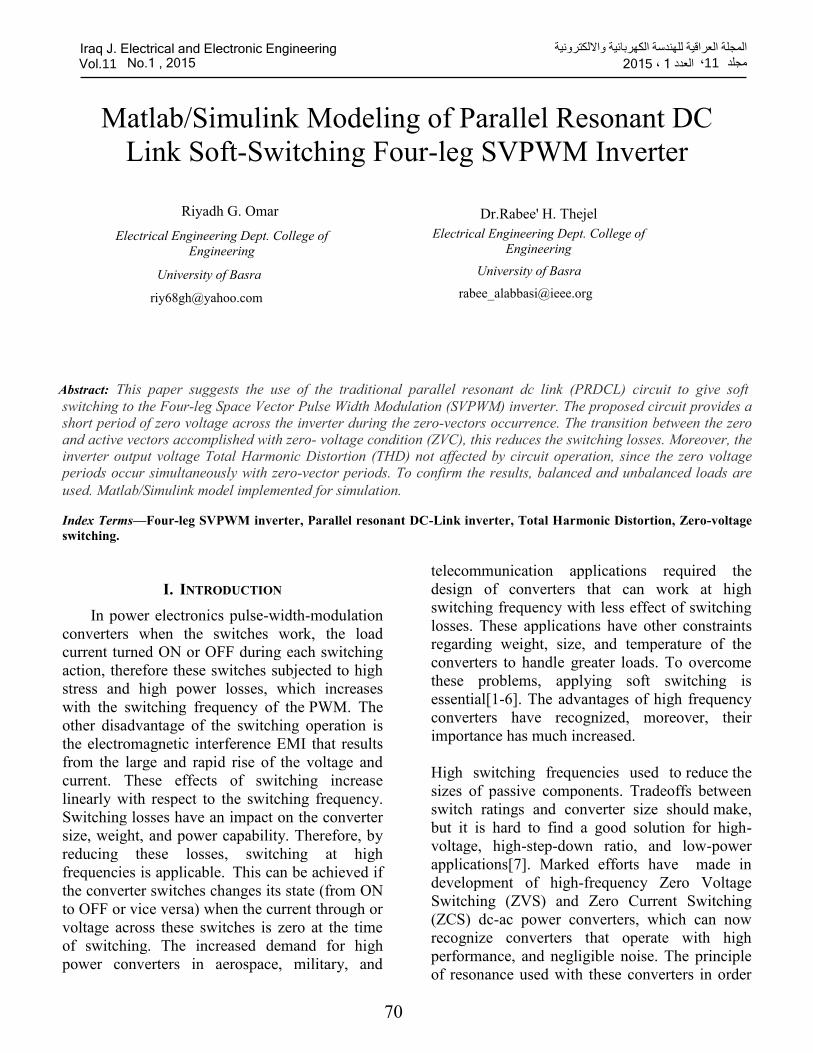
switch S3a turned ON with zero current to build
up the energy in the inductor[8]. The inductor
current rises linearly, since S1a and S2a are at ON
state, see Fig.4.
Mode-2 [t1-t2] At t=t1 adequate energy of (LIP2/2)
is stored in the inductor. The switch S1a turns
OFF at this moment with zero voltage, because
Vc1=E, this energy condition is necessary to
ensure that Vc1 and Vc2 can return to E at the end
of resonant cycle and preparing S1a to turn ON
again with zero voltage condition in the next
operation of resonant circuit, as illustrated in
Fig.4. When S1 is OFF the inductor energy
transfer, and discharge the capacitors C1 and C2
through S2a, therefore the voltage across C1 and
C2 resonant from +E to –Vc1max and the inductor
current will rise from the critical value Ip to peak
current value ILmax, which affect the circuit
operation. The inductor current and capacitors
voltage can be calculated as follows:
IL=(IP + Io) cos ω1 t'+E
zosin ω2 t'-Io (1)
VC1(t)=VC2(t) (2)
VC2(𝑡)=-(IP + Io)𝑧𝑜 cos ω1 t'+E
zo
sin ω2 t'+
E cos ω2 t' (3)
where,
t'=t-t1
C=C1+C2
ω1=1
√LC
zo=√L
C
Mode-3 [t2-t3] The inductor current iL rise to its
peak positive value iLmax, so, Vc1 and Vc2 are
zero since diL/dt=0 at t=t2. In addition, S2a turned
OFF with zero voltage, the PRDCL circuit then
split into two parts, when the voltages Vc1 and Vc2
start to become negative, which is not desirable
for the inverter operation. Therefore to clamp the
negative voltage of Vc2 to zero value, and for
adequate time of zero voltage across the inverter
when the zero space vector occurs, the switch Sr
turns ON at t=t2 since Io connected across the
DC link. The first part of the PRDCL in this
mode is resonant circuit (L-C1) and the second
part is a clamp circuit (C2 and Sr) which
responsible for zero voltage across the device.
The equations of the inductor current and the
capacitors voltage are as follows:
IL(t)=ILmax cosω2t' (4)
VC1(t)=-VC1max sinω2t' (5)
VC2=0
where,
t'=t-t2
ω2=1
√LC1
VC1max=ω2LILmax (6)
Mode-4 [t3-t4] In this mode iL attains the negative
peak value –iLmax, Vc1 changes its value from
negative to zero, since diL dt = 0⁄ at t=t3, then
this voltage changes its direction, at that time S2a
and Sr must be at ON and OFF state respectively,
to allow charging of C1 and C2 with the stored
energy in the next period. The equations for
inductor current and capacitors voltage are as
follows:
ILt=(Io-ILmax) cosω1 t'-Io (7)
VC1(t)=VC2(t)=(ILmax-Io)zo sinω1 t' (8)
where,
t'=t-t3
Mode-5[t4-t5] At t=t4 ,Vc1 and Vc2 attains the
voltage value of E while iL equal to some
negative value , Sa1 is turned ON with zero
voltage again, therefore iL starts to increase
linearly.
Iraq J. Electrical and Electronic Engineeringالمجلة العراقية للهندسة الكهربائية وااللكترونية ، العدد 11مجلد 1 ، 2015 Vol.11 No.1 , 2015
72
Page 4
Mode-6 [t5-t0+Ts] At t= t5, iL returns to zero and
the switch Sa3 is turned OFF with zero current
(natural commutation). After t5, Sa1 and Sa2 are
still ON, while S3, and Sr, stay OFF until time
to + Ts when another zero voltage across the
inverter is requiered. This completes one
switching cycle of the inverter resonant circuit.
By some manipulations, several important design
formulas can be derived as follows[8, 9]:
ILmax=E
zo+Io (9)
VC1max=√L
C1 ILmax (10)
(t2-t1)=1
ω1sin-1 (
E
E+2zoIo) (11)
IP=E
zocot[ω1(t2-t1)] -Io (12)
(t1-to)=L
EIP (13)
(t3-t2)=π
ω2 (14)
(t4-t3) =π
2ω1 (15)
(t5-t4)=L
EIo (16)
Mode-1
Mode-2
Mode-3
Mode-4
Mode-5
Mode-6
Fig.3 Resonant circuit modes of operation.
V. Inverter input current Io
The SVPWM inverter modeled by a current
source whose value changes as a step function
during the resonant transition. Step changes in the
inverter input current inevitably occurs under
normal operating conditions[10]. By addressing
the switching logic sequence and the inverter
phase currents, the current Io can be computed.
Table-1 summarizes the relation between Io with
respect to the phase currents for different
switching patterns of the inverter[11].
Iraq J. Electrical and Electronic Engineeringالمجلة العراقية للهندسة الكهربائية وااللكترونية ، العدد 11مجلد 1 ، 2015 Vol.11 No.1 , 2015
73
Page 5
Fig.4 Resonant circuit waveforms.
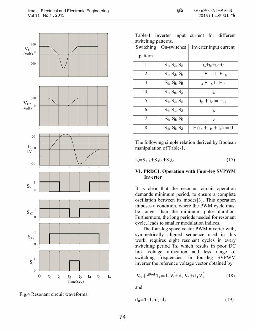
Table-1 Inverter input current for different
switching patterns.
Switching
pattern
On-switches Inverter input current
1 S1, S3, S5 ia+ib+ic=0
2 S1, S3, S2 ‹_ E‹` L F‹a
3 S1, S6, S5 ‹a E‹a L F‹`
4 S1, S6, S2 ia
5 S4, S3, S5 ib + ic = −ia
6 S4, S3, S2 ib
7 S4, S6, S5 ‹c
8 S4, S6, S2 F(ia + ‹b + ic) = 0
The following simple relation derived by Boolean
manipulation of Table-1.
Io=S1ia+S3ib+S5ic (17)
VI. PRDCL Operation with Four-leg SVPWM
Inverter
It is clear that the resonant circuit operation
demands minimum period, to ensure a complete
oscillation between its modes[3]. This operation
imposes a condition, where the PWM cycle must
be longer than the minimum pulse duration.
Furthermore, the long periods needed for resonant
cycle, leads to smaller modulation indices.
The four-leg space vector PWM inverter with,
symmetrically aligned sequence used in this
work, requires eight resonant cycles in every
switching period Ts, which results in poor DC
link voltage utilization and less range of
switching frequencies. In four-leg SVPWM
inverter the reference voltage vector obtained by:
|Vref|ejθref.Ts=d1.V1
+d2.V2 +d3.V3
(18)
and
d0=1-d1-d2-d3 (19)
0 t0 t1 t2 t3 t4 t5 t6-1000
-900
0
900
1000
0 t0 t1 t2 t3 t4 t5 t6-1000
-900
0
900
1000
0 t0 t1 t2 t3 t4 t5 t6
-20
-10
0
10
20
0 t0 t1 t2 t3 t4 t5 t60
1
2
0 t0 t1 t2 t3 t4 t5 t60
1
2
0 t0 t1 t2 t3 t4 t5 t60
1
2
0 t0 t1 t2 t3 t4 t5 t60
1
2
0 t0 t1 t2 t3 t4 t5 t6 Time(sec)
900
0
-900
900
0
20
0
-20
1
0
1
0
1
0
1
0
VC1 (volt)
VC2 (volt)
IL (A)
Sa1
Sa2
Sa3
Sr
”ôçí®˜Üßû•í العراقية للهندسة الكهربائية ”à äß•Iraq J. Electrical and Electronic Engineering ªà ã11 العدد ، 1 ì 2015 Vol.11 No.1 , 2015
74
Page 6
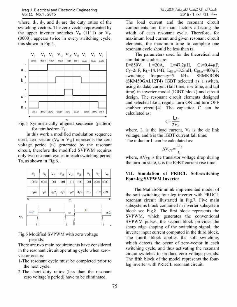
where, d1, d2, and d3 are the duty ratios of the
switching vectors. The zero-vector represented by
the upper inverter switches V0 (1111) or V15
(0000), appears twice in every switching cycle,
this shown in Fig.5.
Fig.5 Symmetrically aligned sequence (pattern)
for tetrahedron T1.
In this work a modified modulation sequence
used, zero-vector (V0 or V15) represents the zero
voltage period (tz) generated by the resonant
circuit, therefore the modified SVPWM requires
only two resonant cycles in each switching period
Ts, as shown in Fig.6.
Fig.6 Modified SVPWM with zero voltage
periods.
There are two main requirements have considered
in the resonant circuit operating cycle when zero-
vector occurs:
1-The resonant cycle must be completed prior to
the next cycle.
2-The short duty ratios (less than the resonant
zero voltage’s period) have to be eliminated.
The load current and the resonant circuit
components are the main factors affecting the
width of each resonant cycle. Therefore, for
maximum load current and given resonant circuit
elements, the maximum time to complete one
resonant cycle should be less than tz.
The parameters used for the theoretical and
simulation studies are:
E=850V, IL=20A, L=47.2µH, C1=0.44µF,
C2=2nF, RL=14.14Ω, Lfilter=3.5mH, Cfilter=400µF,
switching frequency=5 kHz. SEMKRON
(SKM50GAL12T4) IGBT selected as a switch,
using its data, current (fall time, rise time, and tail
time) in inverter model (IGBT block) and circuit
design. The resonant circuit elements designed
and selected like a regular turn ON and turn OFF
snubber circuit[4]. The capacitor C can be
calculated as:
C=Iotf
2Vd
where, Io is the load current, Vd is the dc link
voltage, and tf is the IGBT current fall time.
The inductor L can be calculated as:
∆VCE=LIo
tr
where, ΔVCE is the transistor voltage drop during
the turn-on state, tr is the IGBT current rise time.
VII. Simulation of PRDCL Soft-switching
Four-leg SVPWM Inverter
The Matlab/Simulink implemented model of
the soft-switching four-leg inverter with PRDCL
resonant circuit illustrated in Fig.7. Five main
subsystems block contained in inverter subsystem
block see Fig.8. The first block represents the
SVPWM, which generates the conventional
SVPWM pulses, the second block provides the
sharp edge shaping of the switching signal, the
inverter input current computed in the third block.
The fourth block applies the soft switching,
which detects the occur of zero-vector in each
switching cycle, and thus activating the resonant
circuit switches to produce zero voltage periods.
The fifth block of the model represents the four-
leg inverter with PRDCL resonant circuit.
0000 0001 1001 1101 1111 1101 1001 0001 0000
V0 V1 V9 V13 V9V13V15 V1 V0
1
0
0
0
0
1
1
1
d0/4 d1/2 d2/2 d3/2 d0/2 d3/2 d2/2 d1/2 d0/4
Sa
Sb
Sc
Sn
Ts
V0 V1 V9 V13 V15 V13 V9 V1 V0
a
b
c
n
Iraq J. Electrical and Electronic Engineeringالمجلة العراقية للهندسة الكهربائية وااللكترونية ، العدد 11مجلد 1 ، 2015 Vol.11 No.1 , 2015
75
Page 7
Fig.7 Implemented Matlab/Simulink model of the
soft-switching four-leg inverter.
Fig.8 Subsystems contained in inverter subsystem
block.
The internal construction of switch pulse
block contains relational operator blocks for
shaping the edges of switching pulses for accurate
timing. This is shown in Fig.9. The third block is
(Io computing) which is responsible for predicting
and computing inverter input current necessary to
control resonant circuit using Table-1 and Eq.17.
In addition, average input DC power is computed
in this block, see Fig.10.
Fig.9 Inner diagram of (switch pulse) block.
Fig.10 Inner diagram of (I0 calc.) block.
The fourth block is the (soft-switching), in
this block many logic blocks are used to detect
the occurrence of zero-vector (1111 or 0000) in
each switching cycle to activate the resonant
circuit switches, also controlling the (ON / OFF)
period for each switch. Figure 11 shows the
details of this block. Inside this block there is
(resonant cycle timing) block, which receives
inverter input current, capacitor voltage, and
inductor current as input signals, then computing
critical inductor current value (IP) for successful
resonant circuit operation, also the different time
periods and maximum inductor current are
computed in this block. These values are used to
generate the required switching commands (ON
or OFF) to control the resonant circuit operation
and hence the exact timing to each modes of
Inverter
La
Lb
Lc
Ca
Cb Cc
Rc
Rb
Ra
Ph.a
Ph.b
Ph.c
Ia
Ib
Ic
In
G7
G1
G3
G5
G8
G4
G6
G2
G1a
G2a
G3a
S1a
S3a
S2a
Sr
Ph. A
Ph. B
Ph. C N
Inverter1
I0
ia
ib
ic
Ts1
Ts3
Ts3
I0 calc.
SVPWM
S.Sw
Sw.pulse
S1*
S3*
S5*
S7*
S4*
S6*
S2*
S8*
S1
S3
S5
S7
S4
S6
S2
S8
1
2
3
4
OR
OR
TS1
TS3
TS5
o
Ia
Ib
Ic
E
mean
value
Iraq J. Electrical and Electronic Engineeringالمجلة العراقية للهندسة الكهربائية وااللكترونية ، العدد 11مجلد 1 ، 2015 Vol.11 No.1 , 2015
76
Page 8
operation in each dependent cycle. The detail
construction of this block is shown in Fig.12.
Fig.11 Inner diagram of (soft-switching) block.
Fig.12 Detail diagram for (resonant cycle timing)
block.
The last block (inverter1) contains the inverter
switches and resonant circuit elements, IGBT
blocks are used, and its parameters selected
according to manufacturer data sheet. The
inverter internal block and its connections are
shown in Fig.13.
Fig.13 Four-leg inverter block with PRDCL
resonant circuit.
VIII. Simulation Results
Matlab/Simulink program is used to simulate
PRDCL four-leg inverter. The selection process
of the resonant circuit components parameters,
based on the design formulas and the necessary
considerations, which discussed in the previous
section. Both balanced and unbalanced inverter
loads used to confirm the resonant circuit results.
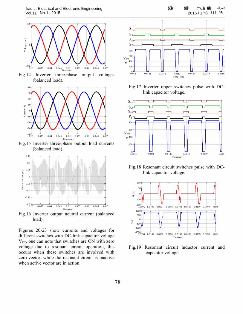
Figures (14-16) show the three-phase inverter
output voltages, load currents, and neutral current
for balanced load. These figures show that the
main features of the four-leg inverter are fulfilled
when the PRDCL circuit is added to the inverter.
The four-leg inverter switches (S1, S3, S5, and S7)
firing pulse with capacitor voltage VC2, shown in
Fig.17. During zero-vector (1111 or 0000)
occurrence, the capacitor voltage value is zero.
This verifies the simultaneous operation of the
resonant circuit with zero-vector occurrence. The
resonant circuit switches (Sa1, Sa2, Sa3, and Sr)
sequences of operation with DC-link capacitor
voltage VC2, shown in Fig.18, which confirm with
the resonant circuit analysis, see Fig.4. The
resonant circuit principle of operation states that,
the maximum inductor current occurs when
capacitor voltage is zero and vice versa. This is
clearly shown in Fig.19.
Monostabl
e
Monostabl
e
S1
S3
S5
S7
Io
IL
VC1
S1a
*
S2a
*
S3a
*
Sr
S1a
S2a
Sr
S3a
Resonant cycle
timing
S3a*
IL
Io
VC1
t2 IP
ILmax
S1a*
S2a*
Sr
Monost
a.
Monost
a.
S1a
S2a
S3a
L
C1
C2
S7 S1 S
3 S
5
S8 S
4 S
6 S
2
VDC
G1 G7 G3 G5
G8 G4 G6 G2
con4 con1 con2 con3
VC1
IL
Iraq J. Electrical and Electronic Engineeringالمجلة العراقية للهندسة الكهربائية وااللكترونية ، العدد 11مجلد 1 ، 2015 Vol.11 No.1 , 2015
77
Page 9
Fig.14 Inverter three-phase output voltages
(balanced load).
Fig.15 Inverter three-phase output load currents
(balanced load).
Fig.16 Inverter output neutral current (balanced
load).
Figures 20-23 show currents and voltages for
different switches with DC-link capacitor voltage
VC2, one can note that switches are ON with zero
voltage due to resonant circuit operation, this
occurs when these switches are involved with
zero-vector, while the resonant circuit is inactive
when active vector are in action.
Fig.17 Inverter upper switches pulse with DC-
link capacitor voltage.
Fig.18 Resonant circuit switches pulse with DC-
link capacitor voltage.
Fig.19 Resonant circuit inductor current and
capacitor voltage.
0.03 0.035 0.04 0.045 0.05 0.055 0.06 0.065 0.07-500
0
500
Time (sec)
Volt
age
(volt
)
0.03 0.035 0.04 0.045 0.05 0.055 0.06 0.065 0.07-40
-30
-20
-10
0
10
20
30
40
Time (sec)
Curr
ent
(A)
0.03 0.035 0.04 0.045 0.05 0.055 0.06 0.065 0.07-0.2
-0.15
-0.1
-0.05
0
0.05
0.1
0.15
Time (sec)
Neu
tral
Cu
rren
t (A
)
0.018 0.0181 0.0182 0.0183 0.0184 0.0185 0.01860
200
400
600
800
Time (sec)
0.0145 0.0146 0.0147 0.0148 0.0149 0.0150
200
400
600
800
Time(sec)
0.0196 0.0197 0.0197 0.0198 0.0198 0.0199 0.0199 0.0199 0.02-100
-50
0
50
100
IL(A
)
0.0196 0.0197 0.0197 0.0198 0.0198 0.0199 0.0199 0.0199 0.02-1500
-1000
-500
0
500
1000
Time(sec)
Vc1
S1
S3
S5
S7
VC2
v
VC2
v
Sa1
Sa2
Sa3
Sr
”ôçí®˜Üßû•í ”ô‹Ž‘®ìÜß• ”³ªèìàß ”ôו®Ìß• المجلةIraq J. Electrical and Electronic Engineering ªà ã11 ©ªÌß• ì 1 ì 2015 Vol.11 No.1 , 2015
78
Page 10
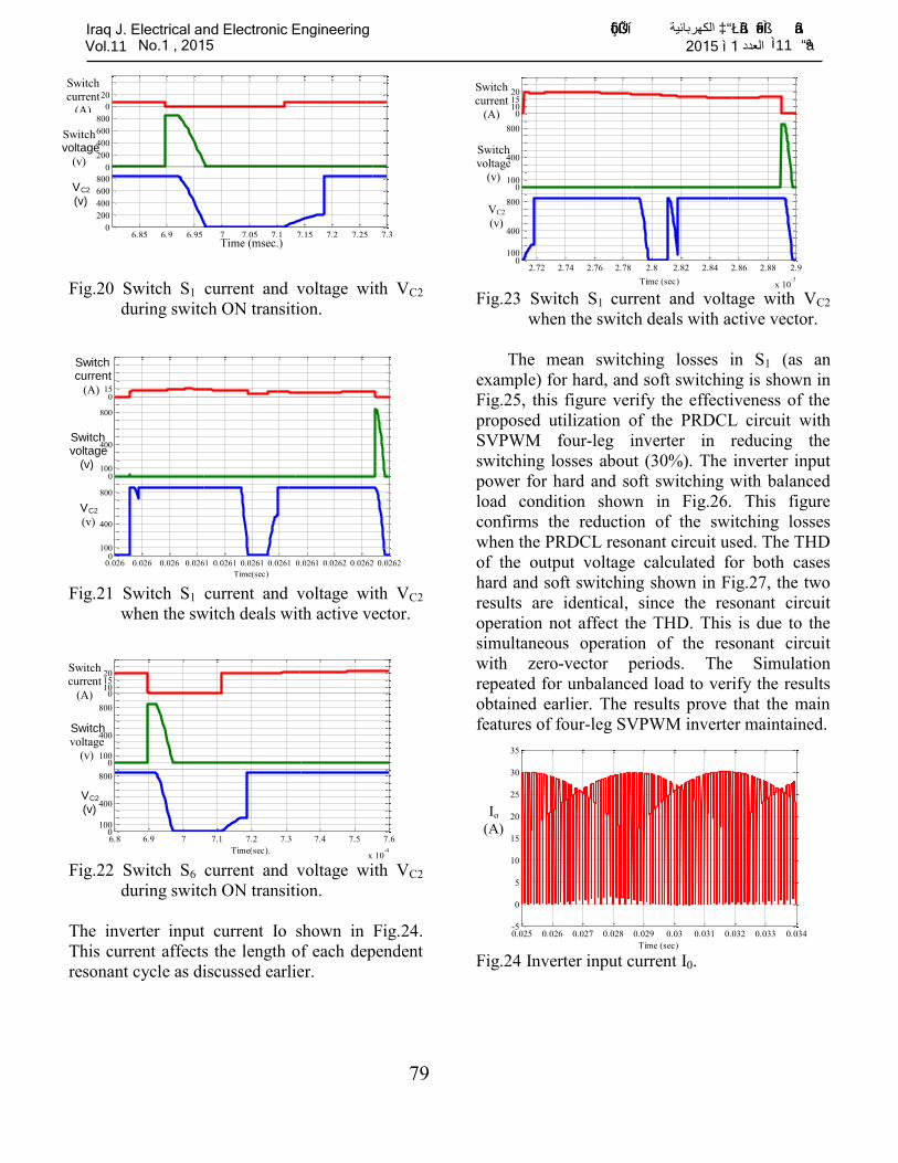
Fig.20 Switch S1 current and voltage with VC2
during switch ON transition.
Fig.21 Switch S1 current and voltage with VC2
when the switch deals with active vector.
Fig.22 Switch S6 current and voltage with VC2
during switch ON transition.
The inverter input current Io shown in Fig.24.
This current affects the length of each dependent
resonant cycle as discussed earlier.
Fig.23 Switch S1 current and voltage with VC2
when the switch deals with active vector.
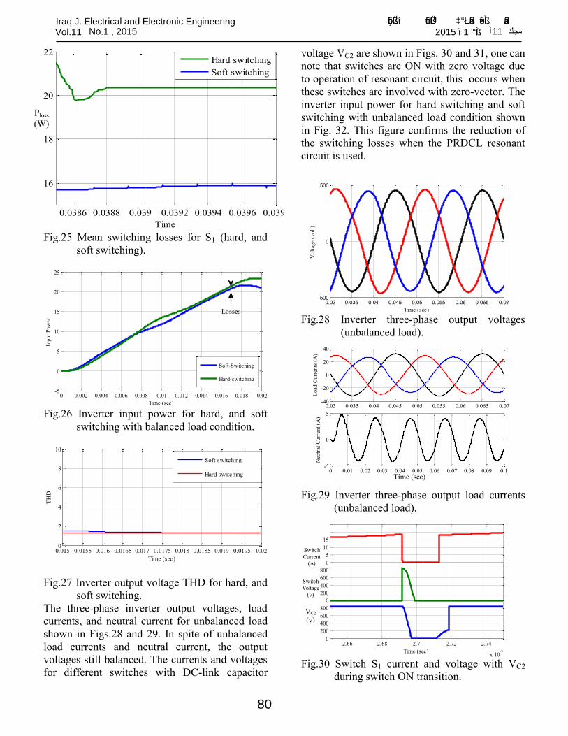
The mean switching losses in S1 (as an
example) for hard, and soft switching is shown in
Fig.25, this figure verify the effectiveness of the
proposed utilization of the PRDCL circuit with
SVPWM four-leg inverter in reducing the
switching losses about (30%). The inverter input
power for hard and soft switching with balanced
load condition shown in Fig.26. This figure
confirms the reduction of the switching losses
when the PRDCL resonant circuit used. The THD
of the output voltage calculated for both cases
hard and soft switching shown in Fig.27, the two
results are identical, since the resonant circuit
operation not affect the THD. This is due to the
simultaneous operation of the resonant circuit
with zero-vector periods. The Simulation
repeated for unbalanced load to verify the results
obtained earlier. The results prove that the main
features of four-leg SVPWM inverter maintained.
Fig.24 Inverter input current I0.
6.85 6.9 6.95 7 7.05 7.1 7.15 7.2 7.25 7.3
x 10-4
0
200
400
600
800
0
200
400
600
800
0
20
Time(sec).
0.026 0.026 0.026 0.0261 0.0261 0.0261 0.0261 0.0261 0.0262 0.0262 0.02620
100
400
800
0100
400
800
015
Time(sec)
6.8 6.9 7 7.1 7.2 7.3 7.4 7.5 7.6
x 10-4
0100
400
800
0100
400
800
0101520
Time(sec).
2.72 2.74 2.76 2.78 2.8 2.82 2.84 2.86 2.88 2.9
x 10-3
0100
400
800
0100
400
800
0101520
Time (sec)
0.025 0.026 0.027 0.028 0.029 0.03 0.031 0.032 0.033 0.034-5
0
5
10
15
20
25
30
35
Time (sec)
Time (msec.)
Switch current
(A)
Switch voltage
(v)
VC2
(v)
Switch current
(A)
Switch voltage
(v)
VC2
(v)
VC2
(v)
Switch voltage
(v)
Switch current
(A)
VC2
(v)
Switch
voltage
(v)
Switch
current
(A)
Io
(A)
”ôçí®˜Üßû•í ³” الكهربائيةªèìàß ”ôו®Ìß• ”à äß•Iraq J. Electrical and Electronic Engineering ªà ã11 العدد ì 1 ì 2015 Vol.11 No.1 , 2015
79
Page 11
Fig.25 Mean switching losses for S1 (hard, and
soft switching).
Fig.26 Inverter input power for hard, and soft
switching with balanced load condition.
Fig.27 Inverter output voltage THD for hard, and
soft switching.
The three-phase inverter output voltages, load
currents, and neutral current for unbalanced load
shown in Figs.28 and 29. In spite of unbalanced
load currents and neutral current, the output
voltages still balanced. The currents and voltages
for different switches with DC-link capacitor
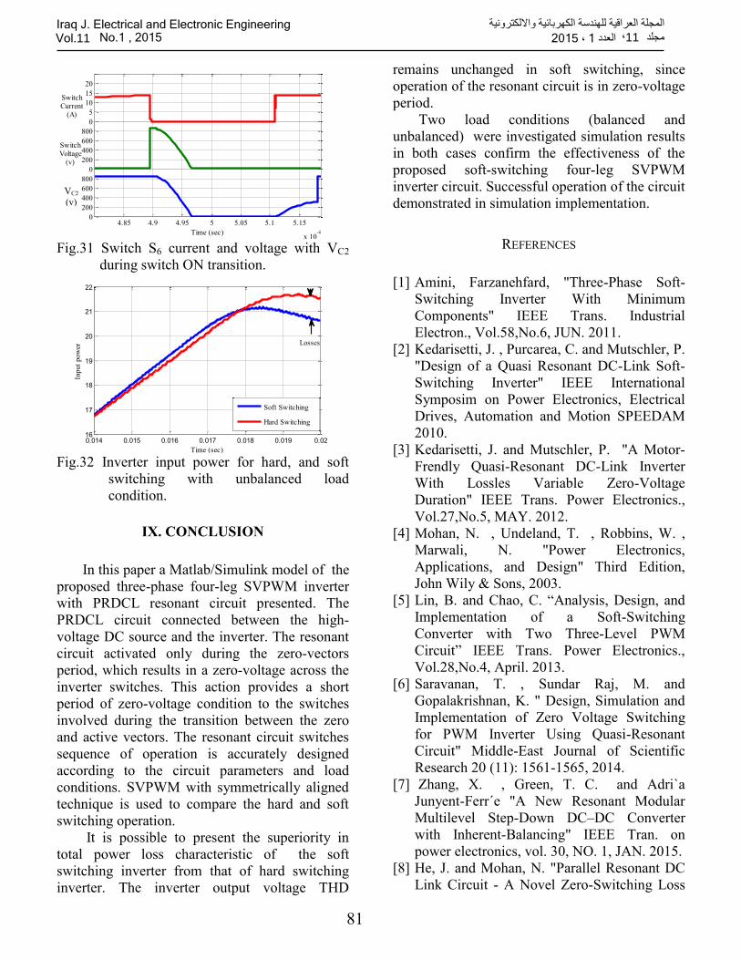
voltage VC2 are shown in Figs. 30 and 31, one can
note that switches are ON with zero voltage due
to operation of resonant circuit, this occurs when
these switches are involved with zero-vector. The
inverter input power for hard switching and soft
switching with unbalanced load condition shown
in Fig. 32. This figure confirms the reduction of
the switching losses when the PRDCL resonant
circuit is used.
Fig.28 Inverter three-phase output voltages
(unbalanced load).
Fig.29 Inverter three-phase output load currents
(unbalanced load).
Fig.30 Switch S1 current and voltage with VC2
during switch ON transition.
0.0386 0.0388 0.039 0.0392 0.0394 0.0396 0.0398
16
18
20
22
Time
Hard switching
Soft switching
0 0.002 0.004 0.006 0.008 0.01 0.012 0.014 0.016 0.018 0.02-5
0
5
10
15
20
25
Time (sec)
Input
Pow
er
Soft-Switching
Hard-switching
Losses
0.015 0.0155 0.016 0.0165 0.017 0.0175 0.018 0.0185 0.019 0.0195 0.020
2
4
6
8
10
Time (sec)
TH
D
Soft switching
Hard switching
0.03 0.035 0.04 0.045 0.05 0.055 0.06 0.065 0.07-500
0
500
Time (sec)V
olt
age
(volt
)
0.03 0.035 0.04 0.045 0.05 0.055 0.06 0.065 0.07-40
-20
0
20
40
Lo
ad C
urr
ents
(A
)
0 0.01 0.02 0.03 0.04 0.05 0.06 0.07 0.08 0.09 0.1-5
0
5
Time (sec)
Neo
tral
Cu
rren
t (A
)
2.66 2.68 2.7 2.72 2.74
x 10-3
0
200
400
600
800
0
200
400
600
800
0
5
10
15
Time (sec)
Switch
Voltage
(v)
Switch
Current
(A)
Time (sec)
VC2
(v)
Ploss
(W)
”ôçí®˜Üßû•í ”ô‹Ž‘®ìÜß• ”³ªèìàß ”ôו®Ìß• ”à äß•Iraq J. Electrical and Electronic Engineering ªÌß• ì© 11مجلد 1 ì 2015 Vol.11 No.1 , 2015
80
Page 12
Fig.31 Switch S6 current and voltage with VC2
during switch ON transition.
Fig.32 Inverter input power for hard, and soft
switching with unbalanced load
condition.
IX. CONCLUSION
In this paper a Matlab/Simulink model of the
proposed three-phase four-leg SVPWM inverter
with PRDCL resonant circuit presented. The
PRDCL circuit connected between the high-
voltage DC source and the inverter. The resonant
circuit activated only during the zero-vectors
period, which results in a zero-voltage across the
inverter switches. This action provides a short
period of zero-voltage condition to the switches
involved during the transition between the zero
and active vectors. The resonant circuit switches
sequence of operation is accurately designed
according to the circuit parameters and load
conditions. SVPWM with symmetrically aligned
technique is used to compare the hard and soft
switching operation.
It is possible to present the superiority in
total power loss characteristic of the soft
switching inverter from that of hard switching
inverter. The inverter output voltage THD
remains unchanged in soft switching, since
operation of the resonant circuit is in zero-voltage
period.
Two load conditions (balanced and
unbalanced) were investigated simulation results
in both cases confirm the effectiveness of the
proposed soft-switching four-leg SVPWM
inverter circuit. Successful operation of the circuit
demonstrated in simulation implementation.
REFERENCES
[1] Amini, Farzanehfard, "Three-Phase Soft-
Switching Inverter With Minimum
Components" IEEE Trans. Industrial
Electron., Vol.58,No.6, JUN. 2011.
[2] Kedarisetti, J. , Purcarea, C. and Mutschler, P.
"Design of a Quasi Resonant DC-Link Soft-
Switching Inverter" IEEE International
Symposim on Power Electronics, Electrical
Drives, Automation and Motion SPEEDAM
2010.
[3] Kedarisetti, J. and Mutschler, P. "A Motor-
Frendly Quasi-Resonant DC-Link Inverter
With Lossles Variable Zero-Voltage
Duration" IEEE Trans. Power Electronics.,
Vol.27,No.5, MAY. 2012.
[4] Mohan, N. , Undeland, T. , Robbins, W. ,
Marwali, N. "Power Electronics,
Applications, and Design" Third Edition,
John Wily & Sons, 2003.
[5] Lin, B. and Chao, C. “Analysis, Design, and
Implementation of a Soft-Switching
Converter with Two Three-Level PWM
Circuit” IEEE Trans. Power Electronics.,
Vol.28,No.4, April. 2013.
[6] Saravanan, T. , Sundar Raj, M. and
Gopalakrishnan, K. " Design, Simulation and
Implementation of Zero Voltage Switching
for PWM Inverter Using Quasi-Resonant
Circuit" Middle-East Journal of Scientific
Research 20 (11): 1561-1565, 2014.
[7] Zhang, X. , Green, T. C. and Adri`a
Junyent-Ferr´e "A New Resonant Modular
Multilevel Step-Down DC–DC Converter
with Inherent-Balancing" IEEE Tran. on
power electronics, vol. 30, NO. 1, JAN. 2015.
[8] He, J. and Mohan, N. "Parallel Resonant DC
Link Circuit - A Novel Zero-Switching Loss
4.85 4.9 4.95 5 5.05 5.1 5.15
x 10-4
0
200
400
600
800
0
200
400
600
800
0
5
10
15
20
Time (sec)
Switch
Current
(A)
Switch
Voltage
(v)
0.014 0.015 0.016 0.017 0.018 0.019 0.0216
17
18
19
20
21
22
Time (sec)
Inp
ut
po
wer
Soft Switching
Hard Switching
Losses
VC2
(v)
Iraq J. Electrical and Electronic Engineeringالمجلة العراقية للهندسة الكهربائية وااللكترونية ، العدد 11مجلد 1 ، 2015 Vol.11 No.1 , 2015
81
Page 13
Topology with Minimum Voltage Stresses,"
IEEE Power Electronics Specialists
Conference Record, 1989, pp. 1006-1012.
[9] He, J. and Mohan, N. "Parallel resonant dc
link circuit-a novel zero switching loss
topology with minimum voltage stresses,"
IEEE Trans. Power Electronics, vol. 6, pp.
687-694, October 1991.
[10] Krogemann, M. " The Parallel Resonant DC
Link Inverter-A Soft-Switching Inverter
Topology with PWM Capability" Theses
submitted to the University of Nottingham for
the degree of Doctor of Philosophy, Feb.
1997.
[11] Lai, J. and Bose, B. "An Improved Resonant
DC Link Inverter For Induction Motor
Drives" IEEE Industry Applications Society
Annual Meeting, 1988, pp.742 - 748 vol.1,
Conference Record of the 1988.
Iraq J. Electrical and Electronic Engineeringالمجلة العراقية للهندسة الكهربائية وااللكترونية ، العدد 11مجلد 1 ، 2015 Vol.11 No.1 , 2015
82