Matrix 210™ QUICK REFERENCE GUIDE Figure A Mounting Holes (4) Ethernet Network Presence LED (for Ethernet Models) 1 3 "Power ON" LED 2 HMI X-PRESS™ Interface 4 Reading Window 5 Device Class Labels 6 NOTE This manual illustrates a Stand Alone application. For other types of installations, such as ID-NET™, Fieldbus, Pass-Through, Multiplexer Layout, etc. and for a complete reader configuration using the VisiSet™ configuration program, refer to the Matrix 210™ Reference Manual available on the DVD and also downloadable from the Web at www.automation.datalogic.com. 4 3 2 1 5 6 1
Transcript
Matrix 210™
QUICK REFERENCE GUIDE
Figure A
Mounting Holes (4) Ethernet Network Presence LED (for Ethernet Models)
1 3
"Power ON" LED 2 HMI X-PRESS™ Interface 4
Reading Window 5
Device Class Labels 6
NOTE
This manual illustrates a Stand Alone application. For other types of installations, such as ID-NET™, Fieldbus, Pass-Through, Multiplexer Layout, etc. and for a complete reader configuration using the VisiSet™ configuration program, refer to the Matrix 210™ Reference Manual available on the DVD and also downloadable from the Web at www.automation.datalogic.com.
4
3 2
1
5
6
1
MATRIX 210™ QUICK GUIDE
2
UPDATES AVAILABILITY
UK/US
The latest drivers and documentation updates for this product are available on Internet. Log on to: www.automation.datalogic.com
I
Su Internet sono disponibili le versioni aggiornate di driver e documentazione di questo prodotto. Collegarsi a: www.automation.datalogic.com
F
Les versions mises à jour de drivers et documentation de ce produit sont disponibles sur Internet. Cliquez sur : www.automation.datalogic.com
D
Im Internet finden Sie die aktuellsten Versionen der Treiber und Dokumentation von diesem Produkt. Adresse : www.automation.datalogic.com
E
En Internet están disponibles las versiones actualizadas de los drivers y documentación de este producto. Dirección Internet : www.automation.datalogic.com
MATRIX 210™ QUICK GUIDE
3
SERVICES AND SUPPORT Datalogic provides several services as well as technical support through its website. Log on to www.automation.datalogic.com and click on the links indicated for further information:
• PRODUCTS
Search through the links to arrive at your product page which describes specific Info, Features, Applications, Models, Accessories, and Downloads including the VisiSet™ utility program, which allows device configuration using a PC. It provides RS232, Ethernet and USB interface configuration.
• SERVICE
- Overview - Warranty Extensions and Maintenance Agreements
- Sales Network- Listing of Subsidiaries, Repair Centers, Partners
Datalogic and the Datalogic logo are registered trademarks of Datalogic S.p.A. in many countries, including the U.S.A. and the E.U.
Matrix 210, ID-NET, VisiSet and X-PRESS are trademarks of Datalogic Automation S.r.l. All other brand and product names mentioned herein are for identification purposes only and may be trademarks or registered trademarks of their respective owners.
Datalogic shall not be liable for technical or editorial errors or omissions contained herein, nor for incidental or consequential damages resulting from the use of this material.
MATRIX 210™ QUICK GUIDE
4
STEP 1 – CONNECT THE SYSTEM 25-Pin Models To connect the system in a Stand Alone configuration, you need the hardware indicated in Figure 1. In this layout the data is transmitted to the Host on the main serial interface. Data can also be transmitted on the RS232 auxiliary interface independently from the main interface selection. When One Shot or Phase Mode Operating mode is used, the reader is activated by an External Trigger (photoelectric sensor) when the object enters its reading zone.
Figure 1 – Matrix 210™ 25-Pin Model in a Stand Alone Layout
CBX100/CBX500 Pinout for Matrix 210™ 25-Pin Models The table below gives the pinout of the CBX100/CBX500 terminal block connectors. Use this pinout when the Matrix 210™ reader is connected by means of the CBX100/CBX500:
Matrix 210™
Host
PG 6000
P.S.*
* External Trigger or Presence Sensor (for One Shot or Phase Mode)
CBX
Main Interface
I/O, AUX
MATRIX 210™ QUICK GUIDE
5
CBX100/500 Terminal Block Connectors Power Outputs
Vdc Power Supply Input Voltage + +V Power Source - Outputs GND Power Supply Input Voltage - -V Power Reference - Outputs Earth Protection Earth Ground O1+ Output 1 +
O1- Output 1 -
Inputs O2+ Output 2 + +V Power Source – External Trigger O2- Output 2 - I1A External Trigger A (polarity insensitive) Auxiliary Interface I1B External Trigger B (polarity insensitive) TX Auxiliary Interface TX -V Power Reference – External Trigger RX Auxiliary Interface RX +V Power Source – Inputs SGND Auxiliary Interface Reference I2A Input 2 A (polarity insensitive) ID-NET™ I2B Input 2 B (polarity insensitive) REF Network Reference -V Power Reference – Inputs ID+ ID-NET™ network +
* Do not leave floating, see Reference Manual for connection details.
CAUTION
Do not connect GND, SGND and REF to different (external) ground references. GND, SGND and REF are internally connected through filtering circuitry which can be permanently damaged if subjected to voltage drops over 0.8 Vdc.
MATRIX 210™ QUICK GUIDE
6
25-Pin Connector Pinout for Matrix 210™ 25-Pin Models The table below gives the pinout of the 25-pin male D-sub connector for connection to the power supply and input/output signals. Use this pinout when the Matrix 210™ reader is connected by means of the 25-pin connector:
25-pin D-sub male connector pinout Pin Name Function 13, 9 Vdc Power supply input voltage + 25, 7 GND Power supply input voltage -
1 CHASSIS Cable shield connected to chassis 18 I1A External Trigger A (polarity insensitive) 19 I1B External Trigger B (polarity insensitive) 6 I2A Input 2 A (polarity insensitive)
* Do not leave floating, see Reference Manual for connection details.
MATRIX 210™ QUICK GUIDE
7
USB Models
NOTE
Before connecting the reader to the USB Port, Install the USB Virtual COM Port Driver from the Support Files\USB Virtual COM Port Drivers directory on the VisiSet Mini-DVD.
The USB Virtual COM Port Driver allows sending serial data using the Matrix 210™ USB port. A different virtual COM Port will be assigned to each connected reader. Installing the USB Virtual COM port drivers:
1. Double-click on the following file to launch the USB Virtual COM Port Driver Installer.
Windows XP/Vista/7 (x32) = "DPInst.exe" Windows Vista/7 (x64) = "DPInst64.exe"
For other operating systems see the readme txt in the Support Files\USB Virtual COM Port Drivers directory. For updated drivers or more details go to ftdichip.com/Drivers/VCP.htm. Configuring the USB Virtual COM port:
Connect the Matrix 210™ USB reader to your PC; a new virtual COM port is associated with the reader. Follow these steps to configure the associated COM Port:
2. Right-click on "My Computer" in the Windows "Start" menu and select "Properties".
3. Select the "Hardware" tab in the System Properties dialog and click the "Device Manager" button.
4. Expand the "Ports (COM & LPT)" item on the "Device Manager" menu. Right-click on "USB Serial Port" and select "Properties".
5. Select the "Port Settings" tab in the "Properties" dialog and click the "Advanced" button.
MATRIX 210™ QUICK GUIDE
8
6. From the "Advanced Settings for COMx" dialog:
• Expand the "COM Port Number" menu and select a new COM Port number if desired (optional).
• Set the "BM Options" -> "Latency Timer" (msec) parameter to 1.
You are now ready to use the new COM Port.
MATRIX 210™ QUICK GUIDE
9
Matrix 210™ USB models can be connected in a Point-to-Point layout to a local host through their USB cable. No external power supply is necessary. The default baud rate is 115200. To maximize data transfer you can set it up to 921600 by configuring the reader though the Communication parameters via VisiSet™. For further details, see the Communication Folder in the VisiSet™ Help On Line.
Figure 3 – Matrix 210™ USB Model in a Point-to-Point Layout
Host
Matrix 210™
MATRIX 210™ QUICK GUIDE
10
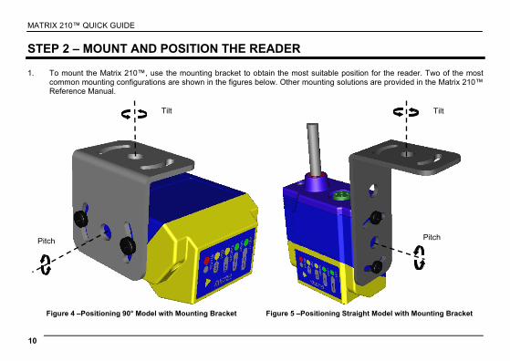
STEP 2 – MOUNT AND POSITION THE READER 1. To mount the Matrix 210™, use the mounting bracket to obtain the most suitable position for the reader. Two of the most
common mounting configurations are shown in the figures below. Other mounting solutions are provided in the Matrix 210™ Reference Manual.
Figure 4 –Positioning 90° Model with Mounting Bracket Figure 5 –Positioning Straight Model with Mounting Bracket
Tilt
Pitch
Tilt
Pitch
MATRIX 210™ QUICK GUIDE
11
2. When mounting the Matrix 210™ take into consideration these three ideal label position angles: Pitch or Skew 10° to 20° and Tilt 0°, although the reader can read a code at any tilt angle.
P
S
Assure at least 10° Minimize Minimize
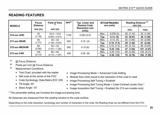
Figure 6 – Pitch, Skew and Tilt Angles 3. Refer to the Reading Features table in the Appendix of this Quick Reference Guide to determine the distance your reader
should be positioned at.
NOTE
Rapid Configuration of the Matrix 210™ reader can be made either through the X-PRESS™ interface (steps 3-4) which requires no PC connection, or by using the VisiSet™ Setup Wizard (steps 5-6). Select the procedure according to your needs.
T
MATRIX 210™ QUICK GUIDE
12
STEP 3 – AIM THE READER Matrix 210™ provides a built-in aiming system to aid reader positioning. The aiming system is accessed through the X-PRESS™ Interface. 1. Power the reader on. During the reader startup (reset or restart phase), all the LEDs blink for one second. On the connector
side of the reader near the cable, the “POWER ON” LED (blue) indicates the reader is correctly powered.
2. Enter the Aim/Locate function by pressing and holding the X-PRESS™ push button until the Aim LED is on.
3. Release the button to enter the Aim function. The aiming system turns on see Figure 7.
4. Place the application specific code in front of the reader at the reading distance indicated for your model in the Reading Features table, centering it in the aiming system indicator.
FOV
default value for:
UHD models
default value for:
NEAR, MEDIUM, FAR models
FOV
Figure 7 – Aiming Function Using The Blue Ring or Internal Lighting System *
green
green
yellow
yellow
red
Figure 8 – X-PRESS™ Interface: Aim Function
* the default value of the Aiming System Status parameter can be changed in VisiSet™.
5. Exit the Aim function by pressing the X-PRESS™ push button once. The aiming system turns off.
MATRIX 210™ QUICK GUIDE
13
STEP 4 – X-PRESS™ CONFIGURATION Once Matrix 210™ is positioned with respect to the code (step 3), you can configure it for optimal code reading relative to your application. This configuration can be performed either through the X-PRESS™ Interface or the VisiSet™ configuration program.
SETUP
1. Enter the Setup function by pressing and holding the X-PRESS™ push button until the Setup LED is on.
2. Release the button to enter the Setup function. The Setup LED will blink until the procedure is completed.
The Setup procedure ends when the Image Acquisition parameters are successfully saved in the reader memory, the Setup LED will remain on continuously and Matrix 210™ emits 3 high pitched beeps.
If the calibration cannot be reached after a timeout of about 5 (five) seconds Matrix 210™ will exit without saving the parameters to memory, the Setup LED will not remain on continuously but it will just stop blinking. In this case Matrix 210™ emits a long low pitched beep.
3. Exit the Setup function by pressing the X-PRESS™ push button once.
green
green
yellow
yellow
red
Figure 9 – X-PRESS™ Interface: Setup Function
MATRIX 210™ QUICK GUIDE
14
LEARN
4. Enter the Learn function by pressing and holding the X-PRESS™ push button until the Learn LED is on.
5. Release the button to enter the Learn function. The Learn LED will blink until the procedure is completed.
The Learn procedure ends when the Image Processing and Decoding parameters are successfully saved in the reader memory, the Learn LED will remain on continuously, the Green Spot is activated and Matrix 210™ emits 3 high pitched beeps
1.
If the calibration cannot be reached after a timeout of about 3 (three) minutes Matrix 210™ will exit without saving the parameters to memory, the Learn LED will not remain on continuously but it will just stop blinking. In this case Matrix 210™ emits a long low pitched beep.
6. Exit the Setup function by pressing the X-PRESS™ push button once.
green
green
yellow
yellow
red
Figure 10 – X-PRESS™ Interface: Learn Function
If you have used this procedure to configure Matrix 210™ go to step 7.
RESET READER TO FACTORY DEFAULT (OPTIONAL)
If it ever becomes necessary to reset the reader to the factory default values, you can perform this procedure by holding the X-PRESS™ push button pressed while powering up the reader. You must keep the X-PRESS™ push button pressed until the power up sequence is completed (several seconds) and all LEDs blink simultaneously 3 times.
All LEDs remain on for about 1 second, then off for one second, the Configuration and Environmental parameters are reset, and the status LED remains on. If connected through a CBX500 with display module, the message "Default Set" is shown on the display. 1 The Learn procedure will not recognize Pharmacode symbologies.
MATRIX 210™ QUICK GUIDE
15
STEP 5 – INSTALLING VISISET™ CONFIGURATION PROGRAM VisiSet™ is a Datalogic reader configuration tool providing several important advantages:
• Setup Wizard for rapid configuration and new users;
• Defined configuration directly stored in the reader;
• Communication protocol independent from the physical interface allowing to consider the reader as a remote object to be configured and monitored.
To install VisiSet™, turn on the PC that will be used for the configuration, running Windows 98, 2000/NT, XP, Vista or 7, then insert the VisiSet™ Mini-DVD, wait for the DVD to autorun and follow the installation procedure. This configuration procedure assumes a laptop computer, running VisiSet™, is connected to the reader's auxiliary port. After installing and running the VisiSet™ software program the following window appears:
Set the communication parameters from the "Options" menu. Then select "Connect", the following window appears:
Figure 11 - VisiSet™ Opening Window Figure 12 - VisiSet™ Main Window After Connection
MATRIX 210™ QUICK GUIDE
16
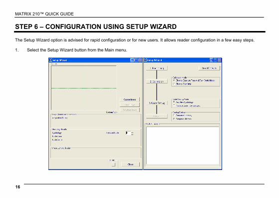
STEP 6 – CONFIGURATION USING SETUP WIZARD The Setup Wizard option is advised for rapid configuration or for new users. It allows reader configuration in a few easy steps. 1. Select the Setup Wizard button from the Main menu.
MATRIX 210™ QUICK GUIDE
17
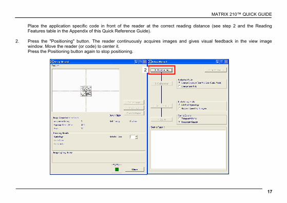
Place the application specific code in front of the reader at the correct reading distance (see step 2 and the Reading Features table in the Appendix of this Quick Reference Guide).
2. Press the "Positioning" button. The reader continuously acquires images and gives visual feedback in the view image
window. Move the reader (or code) to center it. Press the Positioning button again to stop positioning.
2
MATRIX 210™ QUICK GUIDE
18
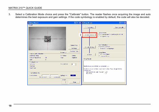
3. Select a Calibration Mode choice and press the "Calibrate" button. The reader flashes once acquiring the image and auto determines the best exposure and gain settings. If the code symbology is enabled by default, the code will also be decoded.
3
MATRIX 210™ QUICK GUIDE
19
4. Select a Code Setting Mode choice and press the "Code Setting" button.
The Setup Result section of the Setup Wizard window shows the code type results and parameter settings.
Setup Result
4
MATRIX 210™ QUICK GUIDE
20
5. Select a Saving Options choice and press the "Save" button.
6. Close the Setup Wizard.
NOTE
If your application has been configured using the VisiSet™ Setup Wizard, your reader is ready. If necessary you can use VisiSet™ for advanced reader configuration.
MATRIX 210™ QUICK GUIDE
21
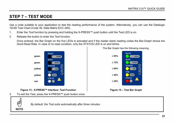
STEP 7 – TEST MODE Use a code suitable to your application to test the reading performance of the system. Alternatively, you can use the Datalogic 1D/2D Test Chart (Code 39, Data Matrix ECC 200).
1. Enter the Test function by pressing and holding the X-PRESS™ push button until the Test LED is on.
2. Release the button to enter the Test function.
Once entered, the Bar Graph on the five LEDs is activated and if the reader starts reading codes the Bar-Graph shows the Good Read Rate. In case of no read condition, only the STATUS LED is on and blinks.
green
green
yellow
yellow
red
The Bar Graph has the following meaning:
≥ 95%
≥ 75%
≥ 60%
≥ 40%
≥ 20%
Figure 13 - X-PRESS™ Interface: Test Function Figure 14 – Test Bar Graph
3. To exit the Test, press the X-PRESS™ push button once.
NOTE
By default, the Test exits automatically after three minutes.
MATRIX 210™ QUICK GUIDE
22
ADVANCED READER CONFIGURATION For further details on advanced product configuration, refer to the complete Reference Manual on the installation Mini-DVD or downloadable from the web site through this link: www.automation.datalogic.com.
The following are alternative or advanced reader configuration methods.
ADVANCED CONFIGURATION USING VISISET™ Advanced configuration can be performed through the VisiSet™ program by selecting Device> Get Configuration From Temporary Memory to open the Parameter Setup window in off-line mode. Advanced configuration is addressed to expert users being able to complete a detailed reader configuration. The desired parameters can be defined in the various folders of the Parameter Setup window and then sent to the reader memory (either Temporary or Permanent):
Figure 15 - VisiSet™ Parameter Setup Window
MATRIX 210™ QUICK GUIDE
23
HOST MODE PROGRAMMING The reader can also be configured from a host computer using the Host Mode programming procedure, by commands via the serial interface. See the Host Mode Programming file on the Mini-DVD.
ALTERNATIVE LAYOUTS (for 25-pin models) If you need to install an Ethernet network, ID-NET™ network, Fieldbus network, Pass-Through network, Multiplexer network or an RS232 Master/Slave refer to the Matrix 210™ Reference Manual. The reader can also be setup for alternative layouts by reading programming barcodes. See the "Setup Procedure Using Programming Barcodes" printable from the Mini-DVD.
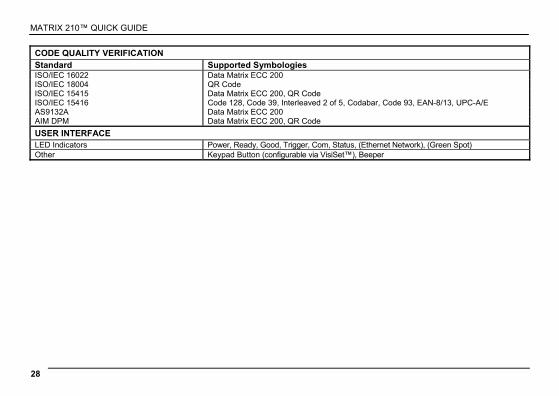
CODE QUALITY VERIFICATION Matrix 210™ can be used as a Code Quality Verifier according to the ISO/IEC 15415, ISO/IEC 15416, AS9132, and AIM DPM Standards.
MATRIX 210™ QUICK GUIDE
24
APPENDIX X-PRESS™ is the intuitive Human Machine Interface designed to improve ease of installation and maintenance.
Status and diagnostic information are clearly presented by means of the five colored LEDs, whereas the single push button gives immediate access to the following relevant functions:
• Learn to self-detect and auto-configure for reading unknown codes
• Setup to perform Exposure Time and Gain calibration.
• Aim/Locate to turn on the blue ring to aid positioning.
• Test with bar graph visualization to check static reading performance
In normal operating mode the colors and meaning of the five LEDs are illustrated in the following table:
READY (green) This LED indicates the device is ready to operate.
GOOD (green) This LED confirms successful reading.
TRIGGER (yellow) This LED indicates the status of the reading phase.
COM (yellow) This LED indicates active communication on main serial port.
STATUS (red) This LED indicates a NO READ result.
During the reader startup (reset or restart phase), all the LEDs blink for one second.
For Ethernet models, on the connector side of the reader near the Ethernet connector, the orange ETHERNET NETWORK PRESENCE LED indicates the on-board Ethernet network connection.
On the connector side of the reader near the cable, the blue POWER ON LED indicates the reader is correctly powered.
Figure 16 – Power and On-Board Ethernet Network LEDs
Power Supply Voltage 10 to 30 Vdc 10 to 30 Vdc 5 Vdc
Consumption 0.35 to 0.13 A, 3.9 W max 0.16 A @ 24 V
0.4 to 0.15 A, 4.5 W max 0.18 A @ 24 V
0.5 A, 2.5 W max
Communication Interfaces Main - RS232 - RS485 full-duplex - RS485 half-duplex
2400 to 115200 bit/s 2400 to 115200 bit/s 2400 to 115200 bit/s
2400 to 115200 bit/s 2400 to 115200 bit/s 2400 to 115200 bit/s
Auxiliary - RS232 2400 to 115200 bit/s 2400 to 115200 bit/s ID-NET™ Up to 1MBaud Up to 1MBaud
Ethernet - 10/100 Mbit/s
Inputs: Input 1(External Trigger) and Input 2
Opto-coupled and polarity insensitive
Opto-coupled and polarity insensitive
Outputs: Output 1 and Output 2 Opto-coupled Opto-coupled
USB 2.0 up to 921600 bit/s
OPTICAL FEATURES Image Sensor CMOS sensor with Global Shutter Image Format WVGA (752x480) Frame Rate up to 60 frames/sec. @ full window size Pitch ± 35° Tilt 0° - 360° Lighting System Internal Illuminator LED Safety Class Class 1 to EN60825-1
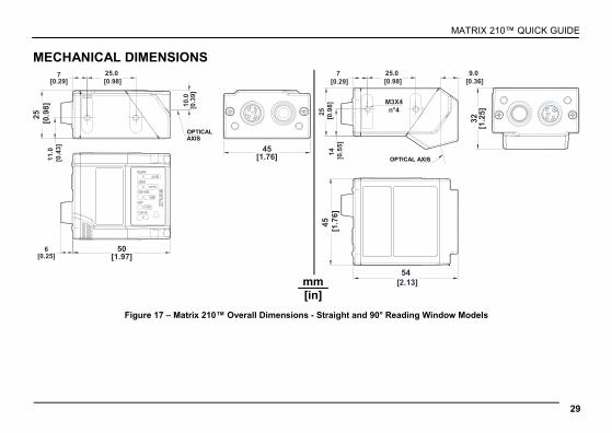
PHYSICAL FEATURES Matrix 210 21x-1xx models Matrix 210 21x-0xx models Dimensions 50 x 25 x 45 mm (1.97 x 0.98 x 1.77 in) 54 x 32 x 45 mm (2.13 x 1.26 x 1.77 in) Weight 190 g. (6.7 oz.) with cable Material Aluminium alloy
MATRIX 210™ QUICK GUIDE
27
ENVIRONMENTAL FEATURES Operating Temperature * 0 to 50 °C (32 to 122 °F) Storage Temperature -20 to 70 °C (-4 to 158 °F) Max. Humidity 90% non condensing Vibration Resistance 14 mm @ 2 to 10 Hz; 1.5 mm @ 13 to 55 Hz; EN 60068-2-6 2 g @ 70 to 200 Hz; 2 hours on each axis Bump Resistance 30g; 6 ms; EN 60068-2-29 5000 shocks on each axis Shock Resistance 30g; 11 ms; EN 60068-2-27 3 shocks on each axis Protection Class EN 60529 IP65
(this symbology requires an activation procedure – contact your local Datalogic Automation distributor for details)
• Australia Post • Royal Mail 4 State
Customer • Kix Code • Japan Post • PLANET • POSTNET • POSTNET (+BB) • Intelligent Mail • Swedish Post
Operating Mode ONE SHOT, CONTINUOUS, PHASE MODE
Configuration Methods X-PRESS™ Human Machine Interface Windows-based SW (VisiSet™) via serial, Ethernet or USB link Serial Host Mode Programming sequences
Parameter Storage Permanent memory (Flash)
* high ambient temperature applications should use metal mounting bracket for heat dissipation.
MATRIX 210™ QUICK GUIDE
28
CODE QUALITY VERIFICATION Standard Supported Symbologies ISO/IEC 16022 Data Matrix ECC 200 ISO/IEC 18004 QR Code ISO/IEC 15415 Data Matrix ECC 200, QR Code ISO/IEC 15416 Code 128, Code 39, Interleaved 2 of 5, Codabar, Code 93, EAN-8/13, UPC-A/E AS9132A Data Matrix ECC 200 AIM DPM Data Matrix ECC 200, QR Code
USER INTERFACE LED Indicators Power, Ready, Good, Trigger, Com, Status, (Ethernet Network), (Green Spot) Other Keypad Button (configurable via VisiSet™), Beeper
PATENTS This product is covered by one or more of the following patents: U.S. patents: 6,512,218 B1; 6,616,039 B1; 6,808,114 B1; 6,997,385 B2; 7,102,116 B2; 7,282,688 B2 European patents: 999,514 B1; 1,014,292 B1; 1,128,315 B1. Additional patents pending.
COMPLIANCE See the Matrix 210™ Reference Manual for the Declaration of Conformity. Only connect Ethernet and dataport connections to a network which has routing only within the plant or building and no routing outside the plant or building.
EMC COMPLIANCE In order to meet the EMC requirements:
• connect reader chassis to the plant earth ground by means of a flat copper braid shorter than 100 mm;
• connect pin "Earth" of the CBX connection box to a good Earth Ground;
• for direct connections, connect the main interface cable shield to pin 1 of the 25-pin connector.
MATRIX 210™ QUICK GUIDE
32
POWER SUPPLY This product is intended to be installed by Qualified Personnel only.
This product is intended to be connected to a UL Listed Computer which supplies power directly to the reader or a UL Listed Direct Plug-in Power Unit marked LPS or “Class 2”, rated 10 to 30 V, minimum 500 mA.
CE COMPLIANCE Warning: This is a Class A product. In a domestic environment this product may cause radio interference in which case the user may be required to take adequate measures.
FCC COMPLIANCE Modifications or changes to this equipment without the expressed written approval of Datalogic could void the authority to use the equipment. This device complies with PART 15 of the FCC Rules. Operation is subject to the following two conditions: (1) This device may not cause harmful interference, and (2) this device must accept any interference received, including interference which may cause undesired operation. This equipment has been tested and found to comply with the limits for a Class A digital device, pursuant to part 15 of the FCC Rules. These limits are designed to provide reasonable protection against harmful interference when the equipment is operated in a commercial environment. This equipment generates, uses, and can radiate radio frequency energy and, if not installed and used in accordance with the instruction manual, may cause harmful interference to radio communications. Operation of this equipment in a residential area is likely to cause harmful interference in which case the user will be required to correct the interference at his own expense.