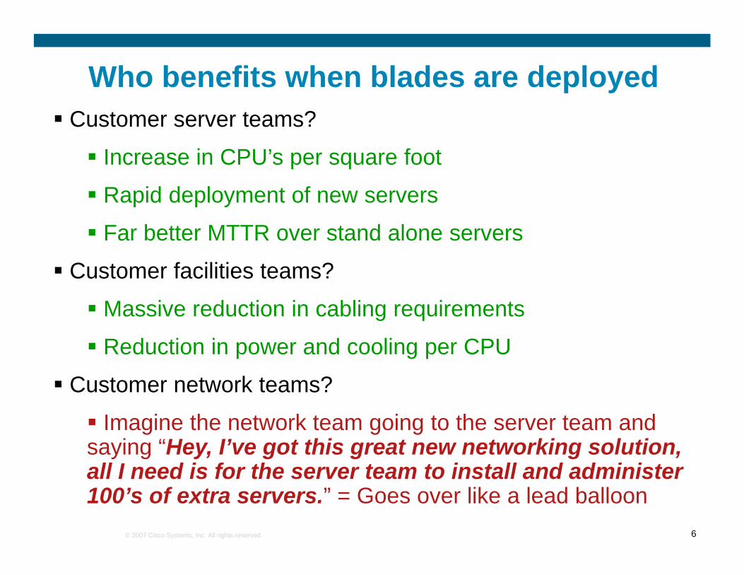
Who benefits when blades are deployedCustomer server teams?
Increase in CPU’s per square foot
Rapid deployment of new servers
Far better MTTR over stand alone servers
Customer facilities teams?
Massive reduction in cabling requirements
Reduction in power and cooling per CPU
Customer network teams?
Imagine the network team going to the server team and saying “Hey, I’ve got this great new networking solution, all I need is for the server team to install and administer
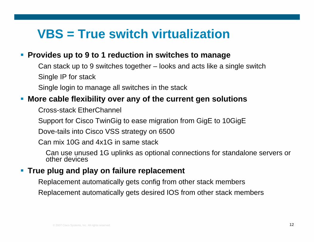
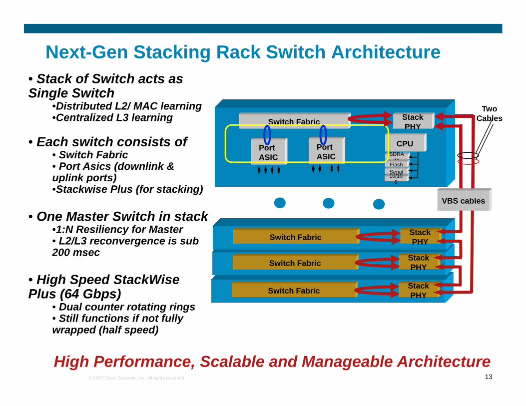
VBS = True switch virtualizationProvides up to 9 to 1 reduction in switches to manage
Can stack up to 9 switches together – looks and acts like a single switchSi l IP f t kSingle IP for stackSingle login to manage all switches in the stack
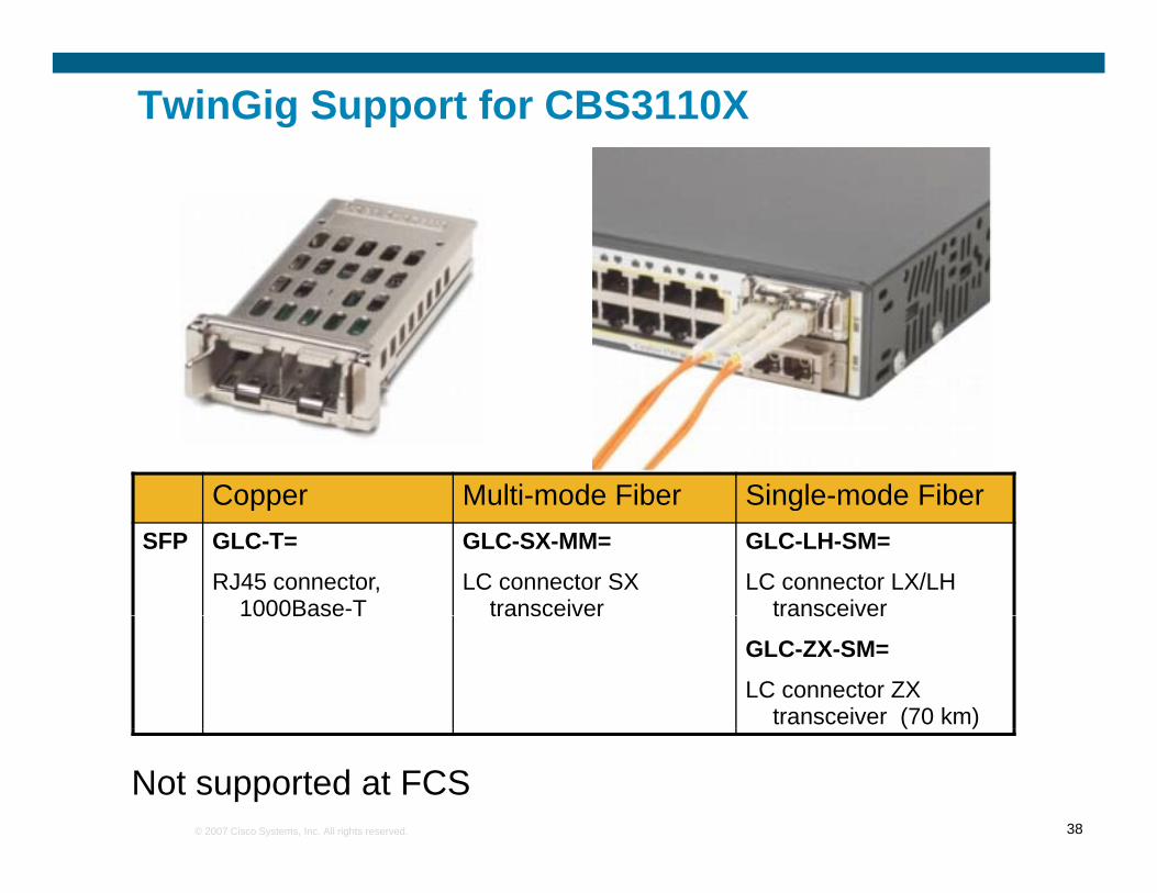
More cable flexibility over any of the current gen solutionsCross-stack EtherChannelSupport for Cisco TwinGig to ease migration from GigE to 10GigEDove-tails into Cisco VSS strategy on 6500Can mix 10G and 4x1G in same stack
Can use unused 1G uplinks as optional connections for standalone servers or other devices
True plug and play on failure replacementReplacement automatically gets config from other stack membersReplacement automatically gets desired IOS from other stack members
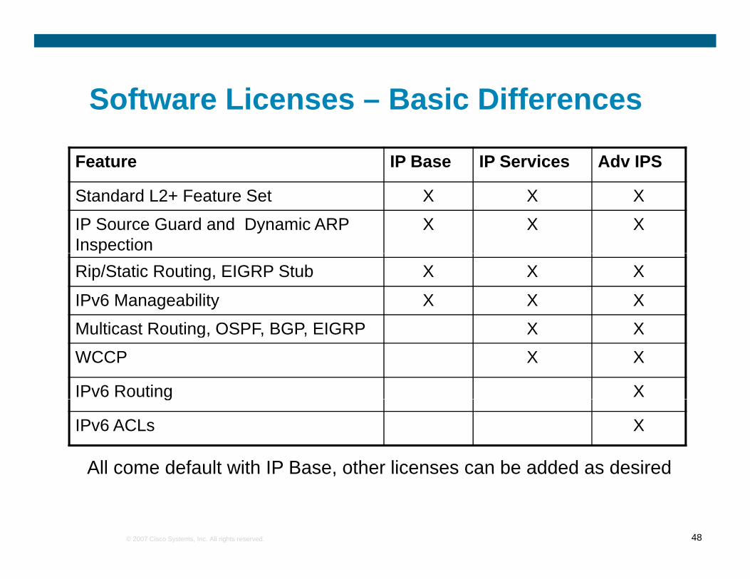
Software: IP Base image included in each part numberIP Services and Advanced IP Services images available only for VBS switches (extra charge)
Software: IP Base image included in each part numberIP Services and Advanced IP Services images available only for VBS switches (extra charge)
Greater design flexibilityEasier to deploy in existing network designs
Single virtual switch looks like a single physical switch to the upstreamReduces design issues with redundant L2 connections
L3 is now a practical option at the blade level!Prior to VBS, L3 was very rarely desired/utilized in blade switchesPrior to VBS, L3 was very rarely desired/utilized in blade switches
Problems with any technology that needed L2 adjacency (clustering, teaming, etc, all common in blade environments) Very difficult to manage many small L3 domains/IP subnetsAll current generation switches have this issue
With VBS, all servers in the stack get L2 adjacencyCan now have up to 56 servers in an L2 blade network, with L3 on the p ,upstream
Allows L2 adjacency to the servers with L3 on the uplinksEliminates Spanning-tree issues on the upstream
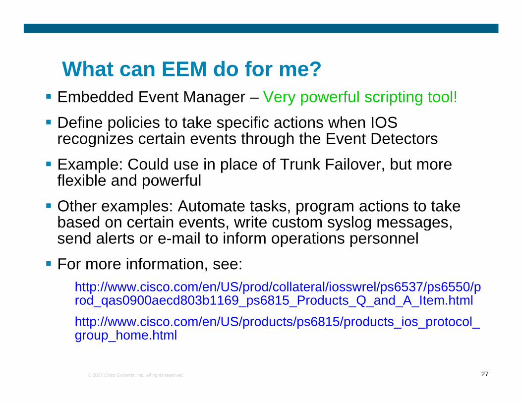
What can EEM do for me?What can EEM do for me?Embedded Event Manager – Very powerful scripting tool!Define policies to take specific actions when IOSDefine policies to take specific actions when IOS recognizes certain events through the Event DetectorsExample: Could use in place of Trunk Failover, but more fl ibl d f lflexible and powerfulOther examples: Automate tasks, program actions to take based on certain events, write custom syslog messages,based on certain events, write custom syslog messages, send alerts or e-mail to inform operations personnelFor more information, see:
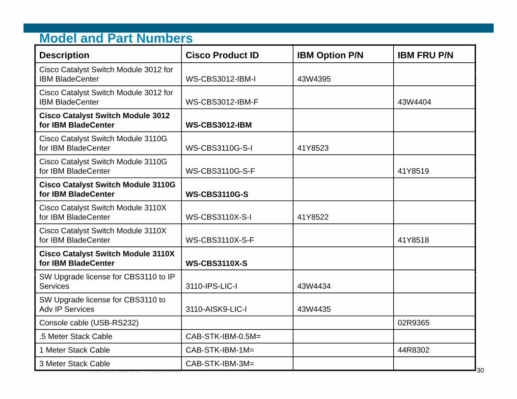
Model and Part NumbersDescription Cisco Product ID IBM Option P/N IBM FRU P/NCisco Catalyst Switch Module 3012 for yIBM BladeCenter WS-CBS3012-IBM-I 43W4395
Cisco Catalyst Switch Module 3012 for IBM BladeCenter WS-CBS3012-IBM-F 43W4404
Cisco Catalyst Switch Module 3012 for IBM BladeCenter WS CBS3012 IBMfor IBM BladeCenter WS-CBS3012-IBM
Cisco Catalyst Switch Module 3110G for IBM BladeCenter WS-CBS3110G-S-I 41Y8523
Cisco Catalyst Switch Module 3110G for IBM BladeCenter WS-CBS3110G-S-F 41Y8519
Cisco Catalyst Switch Module 3110G for IBM BladeCenter WS-CBS3110G-SCisco Catalyst Switch Module 3110X for IBM BladeCenter WS-CBS3110X-S-I 41Y8522
Cisco Catalyst Switch Module 3110X for IBM BladeCenter WS-CBS3110X-S-F 41Y8518
Cisco Catalyst Switch Module 3110X for IBM BladeCenter WS-CBS3110X-SSW U d li f CBS3110 t IPSW Upgrade license for CBS3110 to IP Services 3110-IPS-LIC-I 43W4434
SW Upgrade license for CBS3110 to Adv IP Services 3110-AISK9-LIC-I 43W4435
Mode buttonThe mode button can be used for multipleThe mode button can be used for multiple purposes
Requires a small pointed object to activate
P d l
Example of the Mode button on a 3110G
Press and releaseTurns on the “!” LED on all switches in the stack, and then begins to flash the stack member number on the MBR LED on all switches in the stack for 30on the MBR LED on all switches in the stack for 30 secondsFor example, for stack member 4, it would flash the MBR LED 4 times in a row, then pause briefly, then flash it again 4 times and repeat this for 30flash it again 4 times, and repeat this for 30 seconds
Press and hold down for more then 15 or so secondsseconds
If non-stacked – Resets the switch back to factory default and reloads the switchIf stacked – Resets the entire stack back to factory
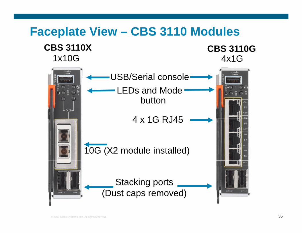
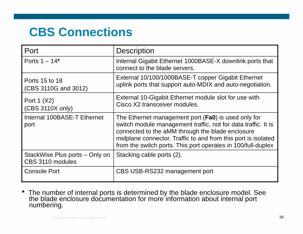
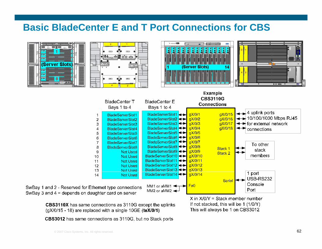
CBS ConnectionsPort DescriptionPorts 1 – 14* Internal Gigabit Ethernet 1000BASE-X downlink ports that
connect to the blade servers.
Ports 15 to 18(CBS 3110G and 3012)
External 10/100/1000BASE-T copper Gigabit Ethernet uplink ports that support auto-MDIX and auto-negotiation.
Port 1 (X2) External 10-Gigabit Ethernet module slot for use with Ci X2 t i d lPort 1 (X2)
(CBS 3110X only) Cisco X2 transceiver modules.
Internal 100BASE-T Ethernet port
The Ethernet management port (Fa0) is used only for switch module management traffic, not for data traffic. It is connected to the aMM through the blade enclosureconnected to the aMM through the blade enclosure midplane connector. Traffic to and from this port is isolated from the switch ports. This port operates in 100/full-duplex
StackWise Plus ports – Only on CBS 3110 modules
Stacking cable ports (2).
* Th b f i t l t i d t i d b th bl d l d l S
CBS 3110 modulesConsole Port CBS USB-RS232 management port
* The number of internal ports is determined by the blade enclosure model. See the blade enclosure documentation for more information about internal port numbering.
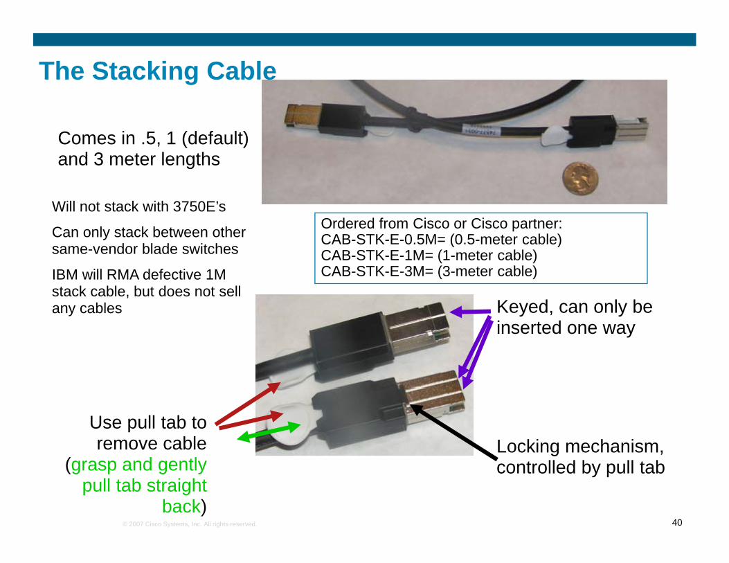
The Stacking Cable
Comes in .5, 1 (default) and 3 meter lengths
Will not stack with 3750E’s
Can only stack between other same endor blade s itches
Ordered from Cisco or Cisco partner:CAB-STK-E-0.5M= (0.5-meter cable)
Keyed, can only be
same-vendor blade switches
IBM will RMA defective 1M stack cable, but does not sell any cables
controlled by pull tab(grasp and gently pull tab straight
back)
Stacking ConsiderationsThe stack cables are different then the cables on current 3750E switches
Can not stack blade switches to non-blade switches (different connectors)
Technically not supposed to stack between blade vendors, but this may or may not be y pp y yblocked via software control (still being considered before FCS)
You do not have to have a complete ring for operationPartial ring will provide half the throughput but will still operateg p g p p
Non-complete ring will result in a design with single points of failure
Not recommended for normal production
Maximum distances can be achieved with 3 meter cablesMaximum distances can be achieved with 3 meter cablesIf desired, every cable can be a 3 meter cable
Probably not practical as some links will have a lot of cable left over
When a new switch is added into a stack, it will reload to sync up with the stackNeed to keep this in mind as it will disrupt traffic for the reloading switch
On the surface, rules for non-VBS stacked switches would seem to apply!But wait…
What makes this different than standalone stacked switches?Standalone stacked switches are not powered and controlled in pairs
Greater chance of two VBS’s being powered off at the same time, creatingGreater chance of two VBS s being powered off at the same time, creatingdouble fault in ring, and ending in separate rings under certain physical stacking
designs (leading to management and other issues)
Standalone stacked switches can be (and usually are) stacked very close together, VBS stacks by their nature of being enclosed within a blade chassis are always stretchedstacks, by their nature of being enclosed within a blade chassis, are always stretched out over the rack
VBS has greater possibility of cable distance issues with the default 1M cable shipped
Examples of good and not so goodEach offer a full ring could be built with 1 meter cables and looks similar But:
No Yes
Each offer a full ring, could be built with 1 meter cables, and looks similar – But:Certain designs could lead to a split ring if an entire BladeCenter is powered down in the stack
For example, in the 4 BC “No” stack
No Yes
BC4
p ,example, if BC 3 had power removed (or an aMM shut down all switch modules in the enclosure), you would end up with two rings, one made up of the switches in BC 1 and 2, and one made up of the switches in BC4 No Yes
BC3
and one made up of the switches in BC4. This, at a minimum would leave each stack contending for the same IP address, and remote switch management would become difficult
No YesThe “Yes” examples also have a better chance of
i t i i BC2maintaining connectivity for the servers in the event a ring does get completely split due
completely split due to multiple faults in the stack
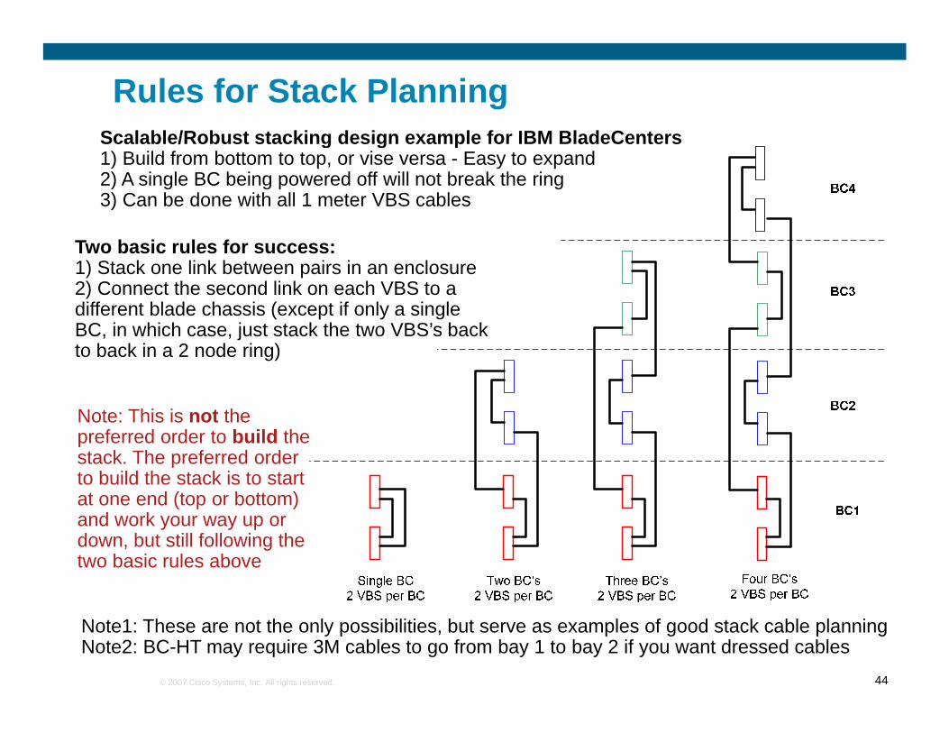
Rules for Stack PlanningScalable/Robust stacking design example for IBM BladeCentersScalable/Robust stacking design example for IBM BladeCenters1) Build from bottom to top, or vise versa - Easy to expand2) A single BC being powered off will not break the ring3) Can be done with all 1 meter VBS cables
Two basic rules for success:1) Stack one link between pairs in an enclosure 2) Connect the second link on each VBS to a different blade chassis (except if only a single BC, in which case, just stack the two VBS’s back to back in a 2 node ring)
Note: This is not theNote: This is not the preferred order to build the stack. The preferred order to build the stack is to start at one end (top or bottom) a o e e d ( op o bo o )and work your way up or down, but still following the two basic rules above
Note1: These are not the only possibilities, but serve as examples of good stack cable planningNote2: BC-HT may require 3M cables to go from bay 1 to bay 2 if you want dressed cables
Example Alternate Stacking Options
Off f ll i dBC4
Offers full ring and no split if a BladeCenter is powered off, but will require purchasing a 3 Meter VBS cable for the one long run (VBS ships
Some base features of all 3XXX switchesSome base features of all 3XXX switchesUp to 128 instances of Spanning Tree supported4K VLAN IDs supported4K VLAN IDs supported1K simultaneous VLANs468 Routed (L3) ports per stack468 Routed (L3) ports per stackUp to 12K MAC addresses supported (depends on template applied)p pp )1K SVI’sSupport for up to 48 EtherChannel ports per switch/stackpp p p pAll of the features of the IGESM – UDLD, CDP, VTP, DTP, RPVST+, Trunk Failover, 9216 byte jumbo frames, etc, etc etc
Supporting Advanced OptionsCBS now offers many routing and advanced functions that the IGESM did not
OSPF, EIGRP, BGP, HSRP, IPV6 support, etc
This will be important to some customers
When discussing routing features – consider engaging your Cisco Systems Engineer
Most server teams will have no clue about this stuff and it will be a lotMost server teams will have no clue about this stuff and it will be a lot of effort to try to educate them on why they might need it, when to use it, and how to deploy it – This is truly network team territory
E th t t k tEngage the customers network team
Engage Cisco field Systems Engineers or Advanced Services
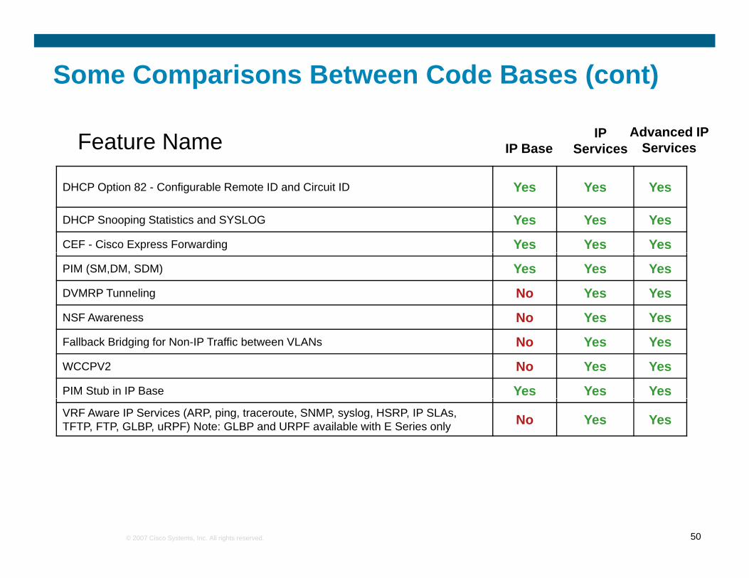
DHCP Option 82 - Configurable Remote ID and Circuit ID Yes Yes Yes
DHCP Snooping Statistics and SYSLOG Yes Yes Yes
CEF - Cisco Express Forwarding Yes Yes Yes
PIM (SM,DM, SDM) Yes Yes Yes
DVMRP Tunneling No Yes Yes
NSF Awareness No Yes Yes
Fallback Bridging for Non-IP Traffic between VLANs No Yes Yes
WCCPV2 No Yes Yes
PIM Stub in IP Base Yes Yes YesVRF Aware IP Services (ARP, ping, traceroute, SNMP, syslog, HSRP, IP SLAs, TFTP, FTP, GLBP, uRPF) Note: GLBP and URPF available with E Series only No Yes Yes
Switch Resources Controlled by TemplatesTemplates let you tune the switch to the environment – reduces wasted resourcesUses Switch Database Management (SDM) Templates to allocate resources depending on desired environmentdepending on desired environment
Benefit A Private VLAN is a way to provide layer 2 isolation between target hosts in the same subnet … (segmentation of IP space can waste lot of addresses)
Deployment Scenario: Servers belonging to different departments or customers can be isolated inside the same blade chassisinside the same blade chassis
Promiscuous portCan communicate with all interfaces, including the isolated and community ports within a PVLANa PVLAN.
Isolated portAn isolated port has complete Layer 2 separation from the other ports within the same PVLAN, but not from the promiscuous ports. PVLANs block all traffic to isolated ports except traffic from promiscuous ports. Traffic from isolated port is forwarded only to promiscuous ports.
Community portCommunicate among themselves and with their promiscuous ports. These interfaces are separated at Layer 2 from all other interfaces in other communities or isolated ports within their PVLAN
For more info on PVLAN:http://www.cisco.com/en/US/tech/tk389/tk814/tk840/tsd_technology_support_sub-
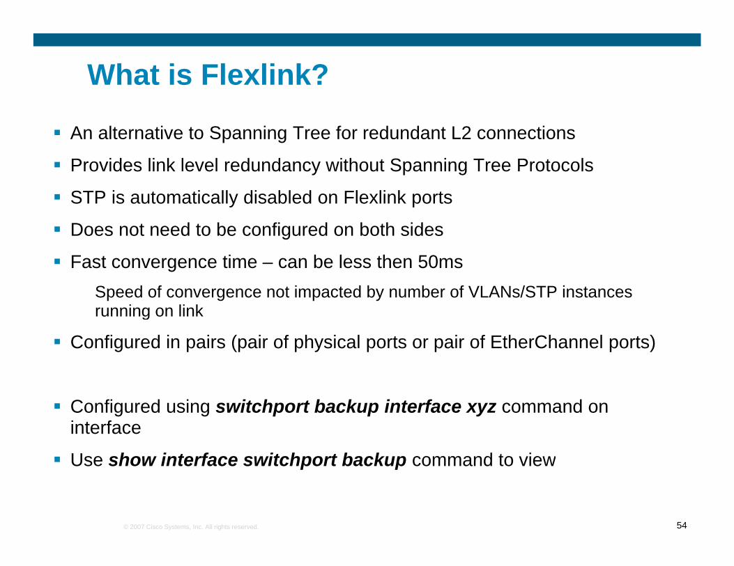
Use show interface switchport backup command to view
Considerations for EtherChannel on uplinksConsiderations for EtherChannel on uplinksStacking virtualizes the physical switches providing more options then previously possible
This does not mean that you can hook anything to anything and expect it to work
BladeCenter
6500 in VSS mode
VSS
6500 in VSS mode
VSS Links
BladeCenter
Optimal – no single points of failure
Example of best solutionUsing virtualized upstream
Using virtualized upstream using redundant sups and multiple line cards
not supported for cross-stack EtherChannel
Considerations for EtherChannel on server facing ports
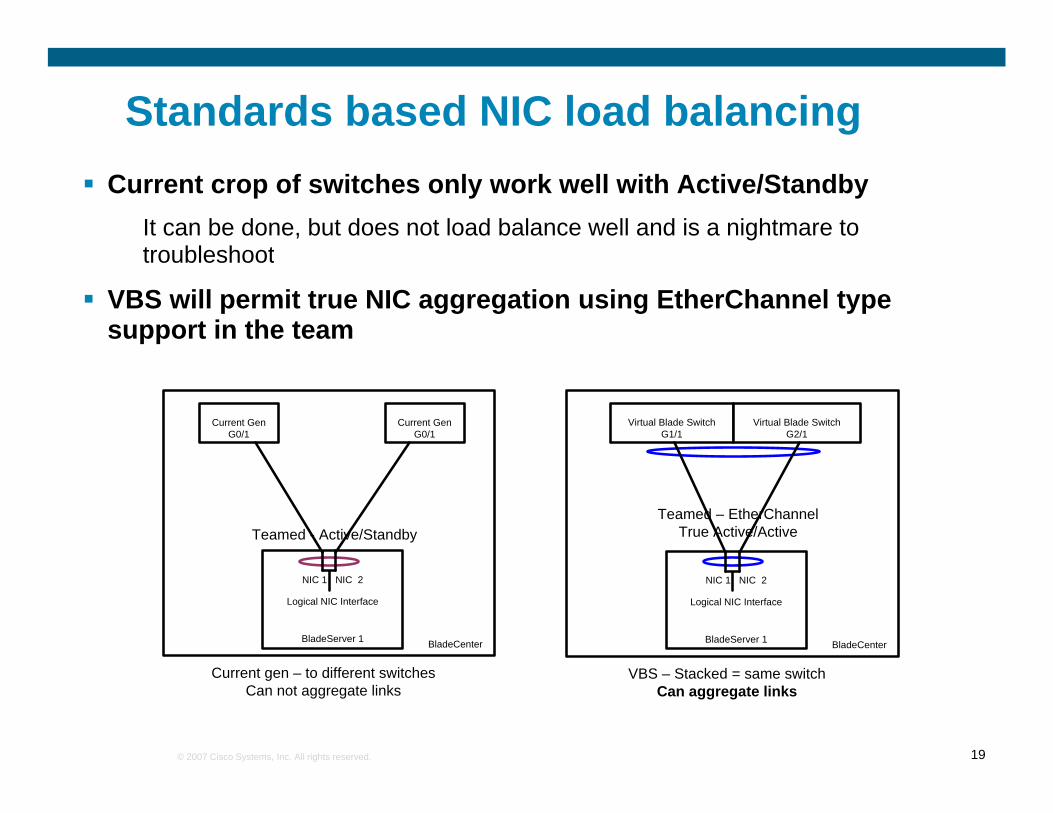
Only possible when switches are stackedIn stacked mode, new options are available for server teaming
802.3AD LACP802.3AD LACPGeneric Trunking (Broadcom term for static aggregation)
To support these new options, you must also configure the ports on the switch facing the serverNote that VBS’s that are NOT stacked can not use these forms of teamingforms of teaming
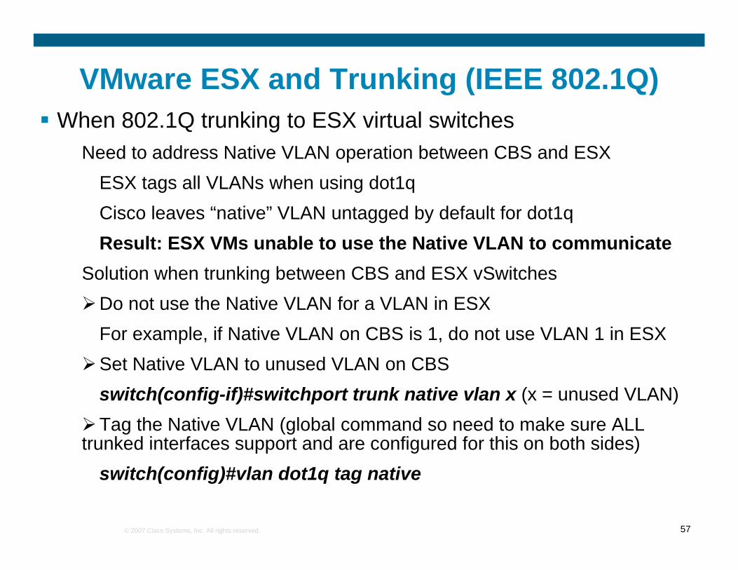
VMware ESX and Trunking (IEEE 802.1Q)When 802.1Q trunking to ESX virtual switches
Need to address Native VLAN operation between CBS and ESXESX t ll VLAN h i d t1ESX tags all VLANs when using dot1qCisco leaves “native” VLAN untagged by default for dot1qResult: ESX VMs unable to use the Native VLAN to communicateResult: ESX VMs unable to use the Native VLAN to communicate
Solution when trunking between CBS and ESX vSwitchesDo not use the Native VLAN for a VLAN in ESX For example, if Native VLAN on CBS is 1, do not use VLAN 1 in ESXSet Native VLAN to unused VLAN on CBSswitch(config if)#switchport trunk native vlan x (x = unused VLAN)switch(config-if)#switchport trunk native vlan x (x = unused VLAN)Tag the Native VLAN (global command so need to make sure ALL
trunked interfaces support and are configured for this on both sides)
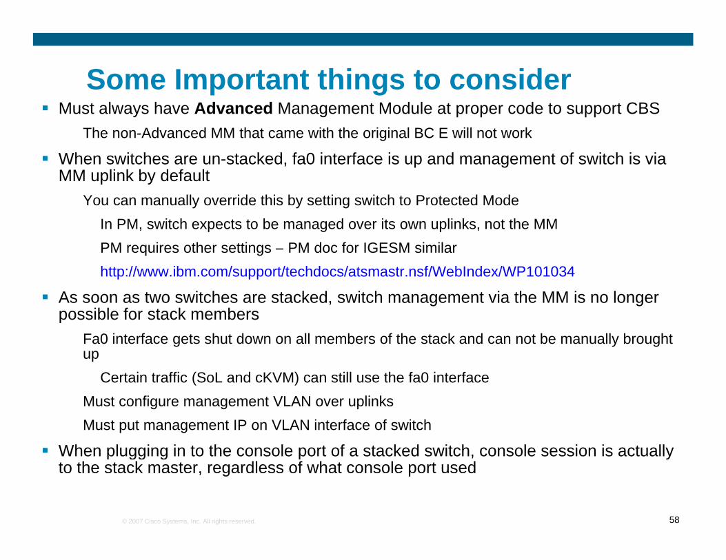
Some Important things to considerM t l h Ad d M t M d l t d t t CBSMust always have Advanced Management Module at proper code to support CBS
The non-Advanced MM that came with the original BC E will not work
When switches are un-stacked, fa0 interface is up and management of switch is via MM uplink by defaultMM uplink by default
You can manually override this by setting switch to Protected ModeIn PM, switch expects to be managed over its own uplinks, not the MMPM i th tti PM d f IGESM i ilPM requires other settings – PM doc for IGESM similarhttp://www.ibm.com/support/techdocs/atsmastr.nsf/WebIndex/WP101034
As soon as two switches are stacked, switch management via the MM is no longer possible for stack memberspossible for stack members
Fa0 interface gets shut down on all members of the stack and can not be manually brought up
Certain traffic (SoL and cKVM) can still use the fa0 interfaceMust configure management VLAN over uplinksMust put management IP on VLAN interface of switch
When plugging in to the console port of a stacked switch, console session is actually
p gg g p , yto the stack master, regardless of what console port used
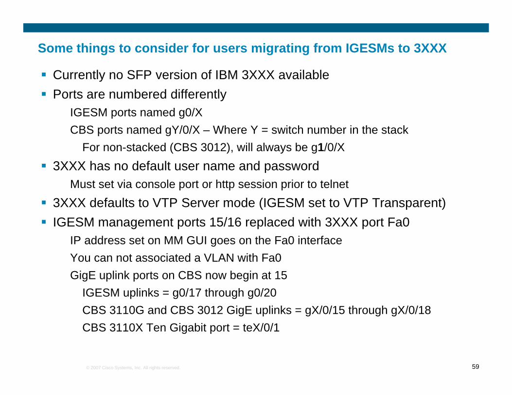
Some things to consider for users migrating from IGESMs to 3XXX
Currently no SFP version of IBM 3XXX availableCurrently no SFP version of IBM 3XXX availablePorts are numbered differently
IGESM ports named g0/XCBS ports named gY/0/X – Where Y = switch number in the stack
For non-stacked (CBS 3012), will always be g1/0/X3XXX has no default user name and passwordp
Must set via console port or http session prior to telnet3XXX defaults to VTP Server mode (IGESM set to VTP Transparent)IGESM management ports 15/16 replaced with 3XXX port Fa0IGESM management ports 15/16 replaced with 3XXX port Fa0
IP address set on MM GUI goes on the Fa0 interfaceYou can not associated a VLAN with Fa0Gi E li k t CBS b i t 15GigE uplink ports on CBS now begin at 15
IGESM uplinks = g0/17 through g0/20CBS 3110G and CBS 3012 GigE uplinks = gX/0/15 through gX/0/18
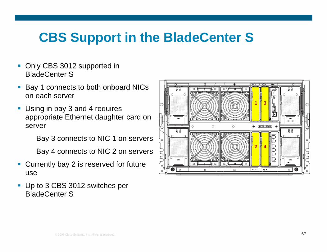
CBS 3110G, CBS 3110X and CBS 3012 d i b 1 2 3 d 4supported in bays 1, 2, 3 and 4
Using in bay 3 and 4 requires appropriate Ethernet daughter card on serverCBS 3012 i l t d i b 7/8CBS 3012 is also supported in bays 7/8 or bay 9/10, if an MSIM is installed and appropriate daughter card on the serverAt this time, each MSIM only supports aAt this time, each MSIM only supports a single 3012 – Working on getting support for 3110 in MSIM as soon as possibleUp to 6 CBS switches per BladeCenter H
Currently any combinations of CBS’s in bays 1 – 4 and a 3012 in each MSIM if installed
interswitch link interposer can be installed that ties ports 13 and 14 in bay 1 to 13 and 14 in bay 2 (same for bays 3 and 4). This is not supported with Cisco switches
1 portUSB-RS232 Console Port
gX/0/13gX/0/14
Fa0
Not usedNot used
aMM1aMM2
Serial
X in X/0/Y = Stack member numberf ( / / )
BladeServerSlot13BladeServerSlot14
SwBay 1 and 2 - Reserved for Ethernet type connectionsSwBay 3 and 4 - depends on daughter card on serverSwBay 7 and 9 – depends on daughter card on server* * For bays 7 and 9 you will need an MSIM to support
If Ethernet switches in bays 3 and 4, ports 13 and 14 from bay 1 and 2 have no connectivityPort 13 and 14 from bay 1 and 2 are only used if SAS controllers are present in bay 3 and/or 4
BladeCenter S – Ethernet I/O connectivityVery different from otherVery different from other BladeCenters
Both on board NICs go to same switch bay (bay 1) in
pairs (Server 1 gets ports 1 and 2, server 3 gets
ports 3 and 4, etc
CBS 3012 is the only CBS switch slated for support in the BladeCenter S
Server daughter cards go to bays 3 and 4 and getbays 3 and 4, and get
Links to More Information3750E stacking white paper
Not exactly VBS, but close and good resource on operation of stackhttp://www.cisco.com/en/US/prod/collateral/switches/ps5718/ps5023/prod_white_paper09186a00801b096a.html
3750E feature comparison/supportCompare 3750E IP Base, IP Services and Advanced IP Serviceshttp://www.cisco.com/en/US/prod/switches/ps5718/ps7077/networking_solutions_products_genericcontent0900aecd805f0eaf.html
CBS Code Download and Release NotesRequires CCO ID (free)
Go to cisco.com->Support->Download Software->Switches Software->Blade Switches->…Blade Switch 3000 Series for IBM
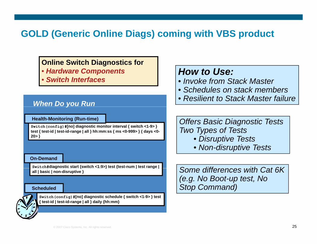
Q&A for 3750EQhttp://www.cisco.com/en/US/products/ps7077/products_qanda_item0900aecd805bbea5.shtmlLink to more information on Generic OnLine Diagnostics (GOLD)
Link to VLAN best practicesLink to VLAN best practiceshttp://www.cisco.com/en/US/products/hw/switches/ps708/products_white_paper09186a008013159f.shtml
Link to BladeCenter troubleshooting documentshttp://www-304.ibm.com/jct01004c/systems/support/supportsite.wss/docdisplay?lndocid=MIGR-57086&brandind=5000020
Free TFTP Server (SolarWinds) for upgrading IOShttp://www.solarwinds.net/Download-Tools.htm
Ethereal/Wireshark – Open source network sniffing tool