MAX2982 EVKIT Operation Manual ___________________________________Last Update: 05/23/11___________________Page1 of 33 MAX2982 Evaluation Kit Operation Manual WARNING: THESE EVALUATION BOARDS ARE NOT FAULT-TOLERANT AND ARE DESIGNED, MANUFACTURED OR INTENDED FOR USE BY PERSONS UNFAMILIAR WITH AND UNTRAINED IN THE PRACTICE OF MEASURING AND DESIGNING WITH HIGH VOLTAGE ELECTRICAL CIRCUITS. THESE EVALUATION BOARDS HAVE 110/220VAC POWER DIRECTLY CONNECTED TO THEIR CIRCUITS, WHICH CAN CAUSE PERSONAL INJURY, DEATH, OR PHYSICAL DAMAGE. THEREFORE, CAUTION SHOULD BE EXERCISED WHEN TESTING THESE DEVICES. YOU MUST BE A SKILLED PERSON IN THE PRACTICE AND ART OF HIGH VOLTAGE CIRCUITRY IN ORDER TO UTILIZE THE CIRCUITS IN THESE EVALUATION BOARDS. THESE EVALUATION BOARDS ARE PROVIDED "AS IS". YOU AGREE NOT TO USE THE BOARDS IN ANY SITUATION WHERE DAMAGE OR INJURY TO PERSONS, PROPERTY OR BUSINESS COULD OCCUR. FURTHERMORE, YOU ASSUME ALL RISK AS TO THE USE, PERFORMANCE AND QUALITY OF THIS MATERIAL AND AGREE TO INDEMNIFY MAXIM FROM ALL LOSSES, CLAIMS, DAMAGES, COSTS, ATTORNEYS' FEES AND OTHER EXPENSES RELATING TO SUCH HIGH RISK ACTIVITY.
Transcript
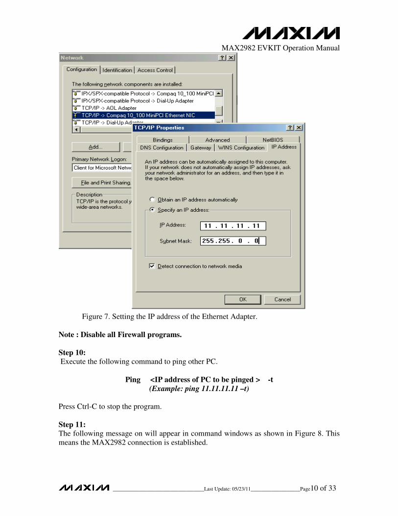
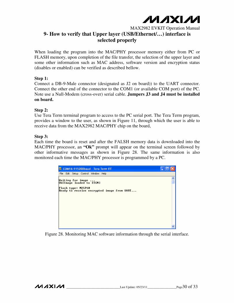
MAX2982 EVKIT Operation Manual
___________________________________Last Update: 05/23/11___________________Page1 of 33
MAX2982 Evaluation Kit Operation Manual
WARNING: THESE EVALUATION BOARDS ARE NOT FAULT-TOLERANT AND ARE
DESIGNED, MANUFACTURED OR INTENDED FOR USE BY PERSONS UNFAMILIAR WITH AND
UNTRAINED IN THE PRACTICE OF MEASURING AND DESIGNING WITH HIGH VOLTAGE
ELECTRICAL CIRCUITS. THESE EVALUATION BOARDS HAVE 110/220VAC POWER DIRECTLY
CONNECTED TO THEIR CIRCUITS, WHICH CAN CAUSE PERSONAL INJURY, DEATH, OR
PHYSICAL DAMAGE. THEREFORE, CAUTION SHOULD BE EXERCISED WHEN TESTING
THESE DEVICES. YOU MUST BE A SKILLED PERSON IN THE PRACTICE AND ART OF HIGH
VOLTAGE CIRCUITRY IN ORDER TO UTILIZE THE CIRCUITS IN THESE EVALUATION
BOARDS.
THESE EVALUATION BOARDS ARE PROVIDED "AS IS". YOU AGREE NOT TO USE THE
BOARDS IN ANY SITUATION WHERE DAMAGE OR INJURY TO PERSONS, PROPERTY OR
BUSINESS COULD OCCUR. FURTHERMORE, YOU ASSUME ALL RISK AS TO THE USE,
PERFORMANCE AND QUALITY OF THIS MATERIAL AND AGREE TO INDEMNIFY MAXIM
FROM ALL LOSSES, CLAIMS, DAMAGES, COSTS, ATTORNEYS' FEES AND OTHER EXPENSES
RELATING TO SUCH HIGH RISK ACTIVITY.
MAX2982 EVKIT Operation Manual
___________________________________Last Update: 05/23/11___________________Page2 of 33
1- Introduction
The evaluation board MAX2982EVKIT is designed to introduce a highly integrated
chipset including the MAX2982 BaseBand (BB) and MAX2981 Analog Front End
(AFE) based on HomePlug 1.0 standard. This system transfers data over 120V or 240V
AC power line. MAX2982 BaseBand uses an Orthogonal Frequency Division
Multiplexing Modulation (OFDM) technique from 4.49MHz to 20.7MHz frequency
band. The main features of the evaluation board are:
• Transporting data over the AC powerline up to 14 Mbps
• Tunable bandwidth and power spectral density (PSD) characteristics of
transmitted OFDM signal, to match the international regulatory requirements
• Excellent Quality of Service (QOS) by adopting various techniques at the
physical layer (PHY) (such as adaptive coding rate technique) and the Media
Access Control (MAC) layer (such as Automatic Repeat request (ARQ)
technique)
• Optimized data rate and minimized error rate by using a link adaptation technique
to adjust dynamically the size of signal constellation (DBPSK or DQPSK) as well
as the rate of Forward Error Correcting (FEC)
• The lowest BOM cost for the complete HomePlug chipset solution
• Multiple digital interfaces such as MII/RMII, FIFO, Ethernet MAC and USB
• Strong immunity to jammer interferences
• Secure communication link using 56-bit DES encryption with key management
MAX2982 EVKIT Operation Manual
___________________________________Last Update: 05/23/11___________________Page3 of 33
2- Minimum System Requirements and Components
• 2 PCs with 233MHz or higher processor clock speed
• 64MB of RAM or higher
• Ethernet network adapter or USB port
• Windows 2000 or higher is required for USB operation
• Windows 95 or higher required for Ethernet operation
• Set of 2 Power line adapter plugs (Included)
• Set of 2 crossover Ethernet cables (Included)
• Set of 2 USB cables (Included)
• Set of 2 Null-Modem DB-9 Serial cables (Included)
• CD-ROM Drive
3- Top view and building blocks of the evaluation board
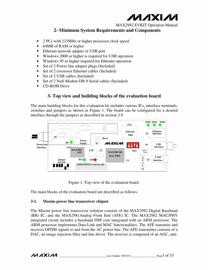
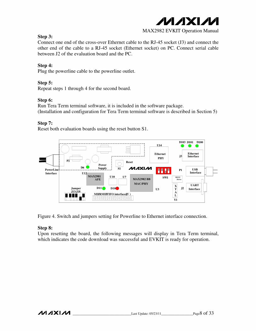
The main building blocks for this evaluation kit includes various ICs, interface terminals,
switches and jumpers as shown in Figure 1. The board can be configured for a desired
interface through the jumpers as described in section 3.9.
PowerLine
Interface
Ethernet Interface
USB Interface
Etherne t
PH Y
L 80225
HomePlug BB
MAC/PHY
MAX 2986
HomePlug AFE
MAX 298
0
Power Supply
Reset
FLASH
X T A L
UART
Interface
MII/RMII/FIFO interface ( J 40)
Jumper J 30:J35 SW1
SW2
UAR T LnDr
v
D6 D7
D9 D119 D 120
D 19
U 12
P1
J3
P2
J 39
Y 1 U 7
S1
U 10
U 1
Ethernet Interface
USB Interface
Ethernet
PH Y
L 80225
HomePlug BB
MAC/PHY
MAX 2986
HomePlug AFE
MAX 298
0
Power Supply
Reset
FLAS H
X T A L
UART
Interface
MII /RMII/FIFO interface ( J40)
Jumper J30: J 35
SW
UAR T LnDr
v
D6
D7
D9 D119 D 120
D 19
U 12
P1
J3
P2
J39
Y1 U7
S1
U10
U1
Ethernet Interface
USB Interface
Ethernet
PHY
HomePlug BB
MAC/PHY
MAX 2986
HomePlug AFE
MAX
0
Power Supply
Reset
FLAS H
X T A L
UART
Interface
MII /RMII
/FIFO interface
(J4 )
Jumper
J30: J 35
SW
UAR
T
LnDr
v
D6
D7
D9 D119 D 120
D19
U12
P1
J3
P2
J39
Y1 U7
S1
U10
U1
Ethernet
Interface
USB
Interface
Ethernet
PHY
MAX2982 BB
MAC
/PHY
MAX2981 AFE
U7
Power Supply
Reset
X T A L
UART
Interface
MII/RMII/ FIFO interface ( J 5 )
Jumper J 13 : J18
SW1
RS232
Driver
D10
D11
D
100D 101 D103
D6
U14
P2
J 3
P1
J 2
Y1
S 1
U 3
U 12
U10
Figure 1. Top view of the evaluation board.
The main blocks of the evaluation board are described as follows.
3-1. Maxim power line transceiver chipset
The Maxim power line transceiver solution consists of the MAX2982 Digital Baseband
(BB) IC, and the MAX2981Analog Front End (AFE) IC. The MAX2982 MAC/PHY
integrated circuit includes a baseband DSP core integrated with an ARM processor. The
ARM processor implements Data Link and MAC functionalities. The AFE transmits and
receives OFDM signals to and from the AC power line. The AFE transmitter consists of a
DAC, an image rejection filter and line driver. The receiver is composed of an AGC, anti-
MAX2982 EVKIT Operation Manual
___________________________________Last Update: 05/23/11___________________Page4 of 33
aliasing filter, high-pass filter and an ADC. The MAX2982 MAC/PHY chip is packaged
in 128-pin LQFP and MAX2981 AFE chip is packaged in 64-pin LQFP.
3-2. AC power line interface
This board is connected to 110/220 Volt power line through an AC power inlet socket P2.
The OFDM signal is transmitted and received through this interface. The power supply
circuitry also uses the AC power line voltage to generate 3.3v and 1.8v DC voltages.
3-3. Clock
There is a single 30 MHz crystal on the board. This crystal drives MAX2982 internal
PLLs to generate all internal clocks as well as a 25 MHz external clock to be used for
MAX2981 AFE.
3-4. UART interface
A DB-9-Male connector for UART interface is provided to download MAC software
from a PC into the MAX2982 MAC/PHY chip. A Null-Modem (cross-over) serial
cable is required for this application and is included in the evaluation package. The
PC’s serial interface must be configured as described in this programmer’s guide. For
UART operations jumpers J3 and J4 must be installed.
3-5. USB interface
The EVKIT supports USB 1.1 interface through a type A USB socket.
3-6. Ethernet interface
The evaluation board provides an RJ45 connector for 10/100 Ethernet interface. Connect
the EVKIT to a PC using a crossover cable and to Hubs/Switches through a straight
Ethernet cable.
3-7. MII/RMII/FIFO interface
A 40-pin header (J5) connector provides access to MII/RMII/FIFO interfaces. The pinout
of the header connector is shown in Figure 2.
MAX2982 EVKIT Operation Manual
___________________________________Last Update: 05/23/11___________________Page5 of 33
Figure 2. MII/RMII/FIFO (J5) connector pinout.
3-8. Flash memory A non-volatile 1-Mbit FLASH memory with SPI Interface is used to store the MAC
firmware code. Two FLASH devices are supported M25P10 (U10) and AT45DB011B
(U7). The MAX2982 MAC/PHY chip can be configured to boot from the FLASH
memory.
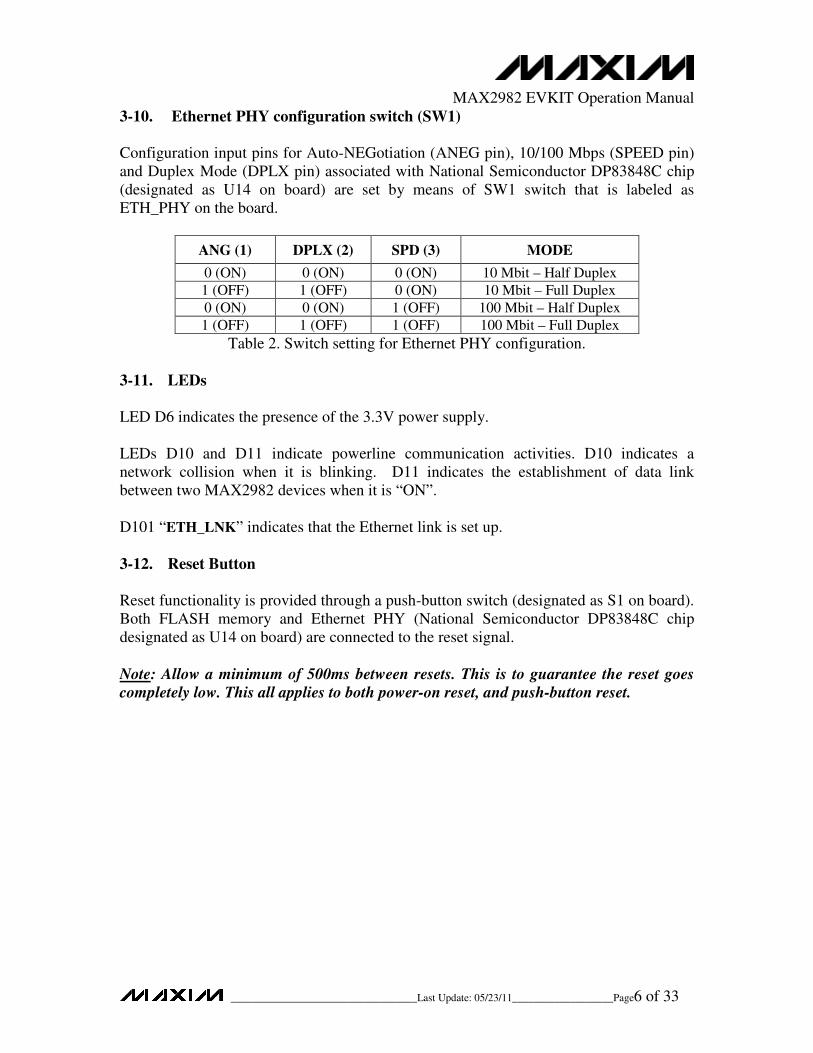
3-9. Jumpers (J13-J18)
Jumpers J13-J15 are the boot jumpers, used to set different boot options for MAX2982
MAC/PHY chip. Depending on these jumpers’ settings, the MAX2982 MAC/PHY chip
can read the MAC software either from FLASH memory, or from the UART interface
using through a PC connected to the EV KIT serial port.
Jumpers J16-J18 are used to set the upper layer interface such as Ethernet, USB, or MII/
RMII/ FIFO interfaces (see Table 1). The MAX2982 MAC/PHY chip reads the jumpers
configuration during boot-up procedure.
Interface ULIS2 (J16) ULIS1 (J17) ULIS0 (J18)
MII 1 (C-to-UP)
0 (C-to-DN)
1 (C-to-UP)
0 (C-to-DN)
0 (C-to-DN)
1 (C-to-UP)
RMII 1 (C-to-UP) 0 (C-to-DN) 1 (C-to-UP)
FIFO 1 (C-to-UP) 0 (C-to-DN) 0 (C-to-DN)
ETH (MII) 0 (C-to-DN) 1 (C-to-UP) 1 (C-to-UP)
USB 1 (C-to-UP) 1 (C-to-UP) 1 (C-to-UP)
Table 1. Jumper J16-J18 settings for upper layer interface selection.
MAX2982 EVKIT Operation Manual
___________________________________Last Update: 05/23/11___________________Page6 of 33


![[ST] Samsung MFP Security Kit Type C V1.0 Eng · TOE 명 Samsung MFP Security Kit Type_C V1.0 TOE Component TFS_FLW_V1.60 TSF_SAA_V1.60 TSF_LUI_V1.60 TSF_SUA_V1.60 TSF_IOW_V1.60 TSF_SFM_V1.60](https://static.documents.pub/doc/80x56/5fc80189a3ec571bb3238e52/st-samsung-mfp-security-kit-type-c-v10-eng-toe-e-samsung-mfp-security-kit-typec.jpg)


