11
November 30, 2017 MAXIMUM DISTANCE 70-80GHZ

November 30,
2017
MAXIMUM DISTANCE 70-80GHZ

2 AVIAT NETWORKS November 30, 2017
TABLE OF FIGURES
FIGURE 1 99.9% 0.1M / 3.97” ANTENNA 2000 MHZ CHANNEL ................................... 4
FIGURE 2 99.9% 0.3M / 1 FT. ANTENNA 2000 MHZ CHANNEL ................................... 5
FIGURE 3 99.9% 0.6M / 2 FT. ANTENNA 2000 MHZ CHANNEL ................................... 5
FIGURE 4 99.99% 0.1M / 3.97” ANTENNA 2000 MHZ CHANNEL ................................. 6
FIGURE 5 99.99% 0.3M / 1 FT. ANTENNA 2000 MHZ CHANNEL ................................. 6
FIGURE 6 99.99% 0.6M / 2 FT. ANTENNA 2000 MHZ CHANNEL ................................. 7
FIGURE 7 99.9% 0.1M / 3.97” ANTENNA 250 MHZ CHANNEL ..................................... 7
FIGURE 8 99.9% 0.3M / 1 FT. ANTENNA 250 MHZ CHANNEL ..................................... 8
FIGURE 9 99.9% 0.6M / 2 FT. ANTENNA 250 MHZ CHANNEL ..................................... 8
FIGURE 10 99.99% 0.1M / 3.97” ANTENNA 250 MHZ CHANNEL .................................. 9
FIGURE 11 99.99% 0.3M / 1 FT. ANTENNA 250 MHZ CHANNEL .................................. 9
FIGURE 12 99.99% 0.6M / 2 FT. ANTENNA 250 MHZ CHANNEL ............................... 10

3 AVIAT NETWORKS November 30, 2017
70-80GHZ MAXIMUM DISTANCE
Calculating Maximum Distance of 70-80GHz Links
There has been significant growth in backhaul products operating in millimeter
frequency range recently. Being subject to rain attenuation, and because different
environments can have different characteristic attenuations, careful and precise
calculation of theoretical distances is critical.
The Aviat Networks data sheet, Maximum Distance 70-80GHz, graphically outlines the
relative distances for different combinations of link characteristics. The graphs represent
maximum distances in different cities around the world. The variables used are 0.1
m/3.97”, 0.3 m/1ft., 0.6 m/2 ft. antenna sizes; 250 MHz and 2000 MHz channel sizes;
and 99.9 percent and 99.99 percent availability requirements.
Note that the graphs show maximum theoretical distances, and that rain attenuation and
other environmental factors native to a city or locale, which can limit transmission range,
are not given any numerical environmental data. However, you can see the range of
differences for the significantly different environments of the major cities represented in
the charts.
Factors Used
Determining the maximum transmission distance for the 70-80GHz radios involves three
main variables: antenna size, channel size, and availability objective. With these three
parameters, you can calculate the maximum theoretical distance between antennas.
Features such as antenna placement, or atmospheric conditions such as rain,
temperature, or electromagnetic interference, are site-specific, and are not discussed or
quantified here or in the data sheet.
Antenna size: The larger your antenna, of course, the greater the transmission distance
your links can cover. However, the effective antenna range is also limited by channel
size and availability objective—these three factors are interdependent. The three sizes
used for comparison in the data sheet are 0.1 meters (3.97 inches), 0.3 meters (1 foot),
and 0.6 meters (2 feet).
Channel size: The smaller the channel size, the greater the maximum transmission
distance. Note that using 2000 MHz channels, 0.1 meter antenna, and an availability
objective of 99.9 percent limits the maximum distance to less than 7 kilometers. Using
the same antenna size and availability goal with 250 MHz channels increases the
maximum distance to around 9 kilometers.

4 AVIAT NETWORKS November 30, 2017
Availability objective: This is the level of availability you need to serve customer
expectations. The two levels commonly used are 99.9 percent and 99.99 percent. Note
that increasing the availability objective from 99.9 percent and 99.99 percent reduces
the maximum distance from 9 kilometers to just over 3 kilometers, given the 0.1 meter
antenna and 2000 MHz channels cited in the examples above.
Figure 1 99.9% 0.1m / 3.97” antenna 2000 MHz channel

5 AVIAT NETWORKS November 30, 2017
Figure 2 99.9% 0.3m / 1 ft. antenna 2000 MHz channel
Figure 3 99.9% 0.6m / 2 ft. antenna 2000 MHz channel

6 AVIAT NETWORKS November 30, 2017
Figure 4 99.99% 0.1m / 3.97” antenna 2000 MHz channel
Figure 5 99.99% 0.3m / 1 ft. antenna 2000 MHz channel

7 AVIAT NETWORKS November 30, 2017
Figure 6 99.99% 0.6m / 2 ft. antenna 2000 MHz channel
Figure 7 99.9% 0.1m / 3.97” antenna 250 MHz channel

8 AVIAT NETWORKS November 30, 2017
Figure 8 99.9% 0.3m / 1 ft. antenna 250 MHz channel
Figure 9 99.9% 0.6m / 2 ft. antenna 250 MHz channel

9 AVIAT NETWORKS November 30, 2017
Figure 10 99.99% 0.1m / 3.97” antenna 250 MHz channel
Figure 11 99.99% 0.3m / 1 ft. antenna 250 MHz channel
10 AVIAT NETWORKS November 30, 2017
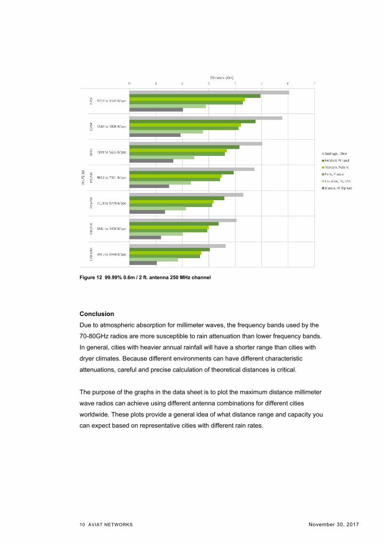
Figure 12 99.99% 0.6m / 2 ft. antenna 250 MHz channel
Conclusion
Due to atmospheric absorption for millimeter waves, the frequency bands used by the
70-80GHz radios are more susceptible to rain attenuation than lower frequency bands.
In general, cities with heavier annual rainfall will have a shorter range than cities with
dryer climates. Because different environments can have different characteristic
attenuations, careful and precise calculation of theoretical distances is critical.
The purpose of the graphs in the data sheet is to plot the maximum distance millimeter
wave radios can achieve using different antenna combinations for different cities
worldwide. These plots provide a general idea of what distance range and capacity you
can expect based on representative cities with different rain rates.

11 AVIAT NETWORKS November 30, 2017
WWW.AVIATNETWORKS.COM
Aviat, Aviat Networks, and Aviat logo are trademarks or registered trademarks of
Aviat Networks, Inc.
© Aviat Networks, Inc. 2017. All Rights Reserved.
Data subject to change without notice.
_wp_70_80_maxdist_112917.doc


