32
Electric cylinder SLZ 63 Maximum flexibility minimum dimensions ...optimal performance 02/2017

Electric cylinder SLZ 63
Maximum flexibilityminimum dimensions
...optimal performance
02/2
017

2 Electric cylinder SLZ 63
Greater application flexibility
Features:
9 Low adjustment speeds
9 Low duty cycle
9 Impact resistant
9Cost-effective applications
9High forces
Move-Teccontinued on page 8
Heavy duty linear cylinder with trapezoidal screw
slow
Your app licationtak es
centre stageWidth, length and height adjustment
3Electric cylinder SLZ 63
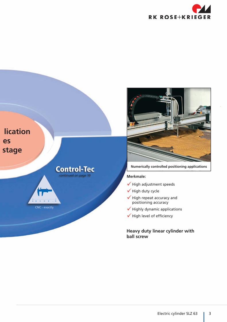
Control-Teccontinued on page 10 Merkmale:
9High adjustment speeds
9High duty cycle
9 High repeat accuracy and positioning accuracy
9Highly dynamic applications
9High level of efficiency
Heavy duty linear cylinder withball screw
CNC - exactly
Your app licationtak es
centre stage
Numerically controlled positioning applications

4 Electric cylinder SLZ 63
Key features / technical benefits
Features:�� Freely selectable drive (three-phase motor / servo mo-tor / stepper motor)
�� Short installation height dueto parallel motor adaption
�� Variable fixation options
�� DIN ISO 15552
The new industrial heavy duty linear cylinder
Options:�� Optional: IP 65
�� Special stroke lengths available on request
�� External magnetic switches
�� Optional gear ratio i= 1:1,5 possible
�� Position for maintenance point upon request
�� Non-rotating stainless steel push rod
�� Service life of up to 8 million double strokes (500 mm stroke with KG spindles)
�� Protection class IP 54
�� Integrated magnetics for external magnetic switches
Freely selectable drive�9 Compatible with all motor manufacturers and types
Ball screw or trapezoidal screw�9 Tailor-made solution for each application
Motor in 90° steps selectable�9 Optimal customised adapting is possible
Slot geometry�9 Connection of accessories or installation of magnetic switches
Push rod�9 Protection against rotation
�9 Simple setting up due to an optical mark to find the zero position of the cylinder

5Electric cylinder SLZ 63
Elektrozylinder SLZ 63- Table of contents
Properties/performance data �� Peripherals overview ........................................... 6
�� General information / operating conditions ............ 8
�� Power diagrams SLZ 63 KG P FL/PL .................... 9
�� Power diagrams SLZ 63 TR P FL/PL ................... 11
Appendix �� Enquiry form ..................................................... 30
Versions(Dimensions, order numbers)
�� SLZ 63 with trapezoidal screw .......................... 12
�� SLZ 63 with ball screw ....................................... 16
Move-Tec
Control-Tec
Accessories �� Guide unit .......................................................... 22
�� Clevis head ......................................................... 24
�� Bearing block for clevis head ........................... 24
�� Swivel head ....................................................... 24
�� Clevis mounting for swivel head ...................... 25
�� Swivel flange ..................................................... 25
�� Bearing block for clevis mounting ................... 25
�� Trunnion support blocks .................................. 26
�� Support blocks for trunnion mounting ........... 26
�� Slot stone ........................................................... 26
�� Motor adaptor kit ............................................ 27
�� Magnetic switch ............................................... 28
Fixing
Drive
Position determination

6 Electric cylinder SLZ 63
Peripherals overviewUnlimited options to adapt standard or customized accessories (front DIN ISO 15552)
�� Swivels, trunnions
�� Base fixings
�� Clevis heads
�� Swivel heads
�� Guiding units
�� Proximity switch
Key features / technical benefits
...and more...

7Electric cylinder SLZ 63

8 Electric cylinder SLZ 63
Technical data Move-Tec / Control-Tec
Technical data
Heavy duty linear cylinder with trapezoidal screw for robust, versatile moving applications (Move-Tec)
General information / operating conditions
* P FL : parallele motor connection / Fastline-version (high spindle pitch)* P PL : parallele motor connection / Powerline-version (low spinle pitch)
Subject to modifications. Latest version on www.rk-rose-krieger.com
Heavy duty linear cylinder with ball screw for precision positioning applications (Control-Tec)
Type SLZ 63 TR PL SLZ 63 TR P PL* SLZ 63 TR FL SLZ 63 TR P FL*
Max. compressive force / tensile force 15.000 N 6.000 N
Max. driving torque 35 Nm
Max. speed 27 mm/s 58 mm/s
Max. acceleration 3 m/s²
Repeatability ± 0,2 mm
Max. no-load torque - < 1,5 Nm - < 1,5 Nm
Drive TR 28x5 TR 28x10
Lead accuracy ≤ 0,05 mm / 300 mm ≤ 0,2 mm / 300 mm
Duty cycle S3 15% S3 40%
Ambient temperature + 0 °C to + 60 °C
Degree of protection IP 54 (optional IP 65)
Continuous sound pressure level < 65 dB (A)
Type SLZ 63 KG PL SLZ 63 KG P PL* SLZ 63 KG FL SLZ 63 KG P FL*
Max. compressive force / tensile force 10.000 N 6.000 N
Max. driving torque 25 Nm 15 Nm
Max. speed 500 mm/s 1250 mm/s
Max. acceleration 10 m/s²
Repeatability ± 0,04 mm
Max. no-load torque - < 1,0 Nm - < 1,0 Nm
Drive KG 25x10 KG 25x25
Lead accuracy T 7 ( ≤ 0,052 mm / 300 mm)
Duty cycle S3 100%
Ambient temperature + 0 °C to + 50 °C
Degree of protection IP 54 (optional IP 65)
Continuous sound pressure level < 75 dB (A)
9Electric cylinder SLZ 63
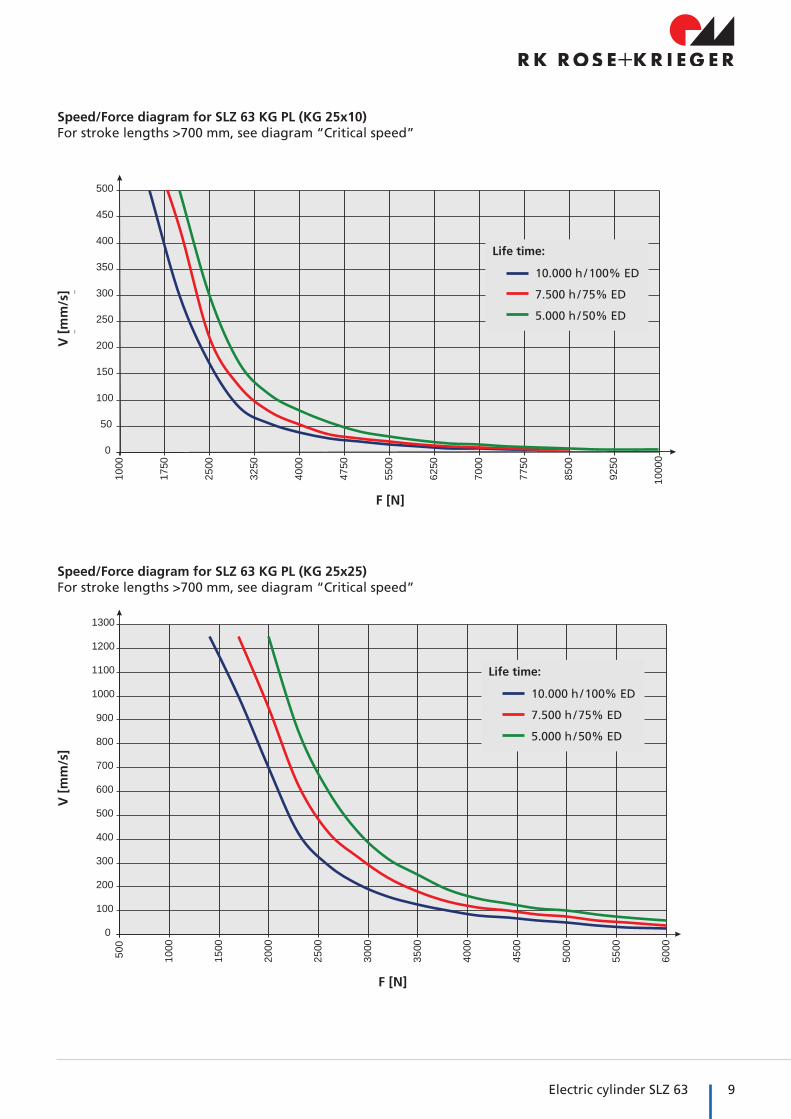
Speed/Force diagram for SLZ 63 KG PL (KG 25x10)For stroke lengths >700 mm, see diagram “Critical speed”
0
50
100
150
200
250
300
350
400
450
500
1000
1750
2500
3250
4000
4750
5500
6250
7000
7750
8500
9250
1000
0
V [m
m/s
]
F [N]
F [N]
V [
mm
/s]
10.000 h / 100% ED
7.500 h / 75% ED
5.000 h / 50% ED
Life time:
Speed/Force diagram for SLZ 63 KG PL (KG 25x25)For stroke lengths >700 mm, see diagram “Critical speed”
0
100
200
300
400
500
600
700
800
900
1000
1100
1200
1300
500
1000
1500
2000
2500
3000
3500
4000
4500
5000
5500
6000
V [m
m/s
]
F [N]
V [
mm
/s]
F [N]
10.000 h / 100% ED
7.500 h / 75% ED
5.000 h / 50% ED
Life time:

10 Electric cylinder SLZ 63
Power diagrams Move-Tec / Control-Tec
Technical data
Force/Performance diagram for SLZ 63 KG FL/PL (KG 25x25 and KG 25x10)All data are theoretical, practical differences are possible.
Speed/Stroke diagram for SLZ 63 KG FL/PL (KG 25x25 and KG 25x10)Critical speed
V [
mm
/s]
0
200
400
600
800
1000
1200
1400
0
100
200
300
400
500
600
700
800
900
1000
V (m
m]
Hub [mm]
0
1000
2000
3000
4000
5000
6000
1000
3000
5000
7000
9000
1100
0
1300
0
1500
0
1700
0
1900
0
2100
0
F [N
]
L [km]
0
2000
4000
6000
8000
10000
0
1000
2000
3000
4000
5000
6000
7000
8000
9000
1000
0
1100
0
1200
0
F [N
]
L [km]
F [N
]F
[N]
L [km]
L [km]
Stroke [mm]
KG 25x25
KG 25x10
KG 25x25
KG 25x10

11Electric cylinder SLZ 63
Stroke [mm]
Speed/Force diagram for SLZ 63 TR FL/PLNote: SLZ 63 TR FL (Tr 28x10) has no self-locking effect.
Force/Stroke diagram for SLZ 63 TR FL/PL and SLZ 63 KG FL/PLSpindle buckling
F [N]
V [
mm
/s]
F [N
]
Note:The specifications are based on experimentally determined and theoretically calculated data at room temperature.
The running performance that can be achieved in practice can deviate from the specified curves under different parameters.
0
10
20
30
40
50
60
750
1500
2250
3000
3750
4500
5250
6000
6750
7500
8250
9000
9750
1050
0
1125
0
1200
0
1275
0
1350
0
1425
0
1500
0
V [m
m]
F [N]
TR 28x10
TR 28x5
0
2000
4000
6000
8000
10000
12000
14000
16000
100
200
300
400
500
600
700
800
900
1000
1100
F [N
]
Hub [mm]
12 Electric cylinder SLZ 63
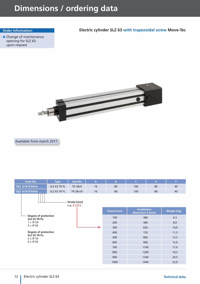
Code No. Type Spindle A B C E F
TQ3_A1A1E3AAA_ _ _ _ SLZ 63 TR PL TR 28x5 16 80 100 80 40
TQ3_A1A1E3DAA_ _ _ _ SLZ 63 TR FL TR 28x10 16 80 100 80 40
Dimensions / ordering data
Electric cylinder SLZ 63 with trapezoidal screw Move-Tec
�� Change of maintenance opening for SLZ 63 upon request
Order information:
Degree of protection SLZ 63 TR PL:1 = IP 543 = IP 65
Degree of protection SLZ 63 TR FL:2 = IP 544 = IP 65
Travel [mm]Installation
dimension X [mm]Weight [kg]
100 380 6,5
200 480 8,0
300 620 10,0
400 720 11,5
500 860 13,5
600 960 15,0
700 1100 17,0
800 1200 18,5
900 1340 20,5
1000 1440 22,0
Stroke [mm]e.g. 0 3 0 0
Technical data
Available from march 2017

13Electric cylinder SLZ 63
G H K L M N O P
M16x1,5 112 88 40 48 56,5 94 18,5
M16x1,5 112 88 40 48 56,5 94 18,5
[mm]
A
A
L + Hub - 100
Einbaumaß XNullstellung
*Standard position of the maintenance opening
Opening to fit coupling
View B
View B
View C
View C
Motor housing in 90 ° steps selectable on request
Standard position:Motor 180°Maintenance opening 270°(see page 30)
Zero position
L + Stroke - 100
Installation dimension X
14 Electric cylinder SLZ 63
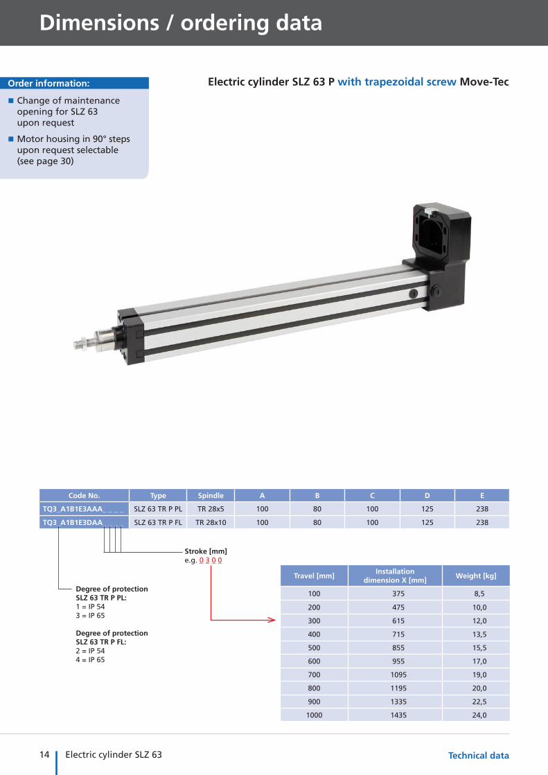
Electric cylinder SLZ 63 P with trapezoidal screw Move-Tec
Dimensions / ordering data
Technical data
�� Change of maintenance opening for SLZ 63 upon request
�� Motor housing in 90° steps upon request selectable (see page 30)
Order information:
Code No. Type Spindle A B C D E
TQ3_A1B1E3AAA_ _ _ _ SLZ 63 TR P PL TR 28x5 100 80 100 125 238
TQ3_A1B1E3DAA_ _ _ _ SLZ 63 TR P FL TR 28x10 100 80 100 125 238
Travel [mm]Installation
dimension X [mm]Weight [kg]
100 375 8,5
200 475 10,0
300 615 12,0
400 715 13,5
500 855 15,5
600 955 17,0
700 1095 19,0
800 1195 20,0
900 1335 22,5
1000 1435 24,0
Stroke [mm]e.g. 0 3 0 0
Degree of protection SLZ 63 TR P PL:1 = IP 543 = IP 65
Degree of protection SLZ 63 TR P FL:2 = IP 544 = IP 65

15Electric cylinder SLZ 63
F G H K L M N O P
40 M16x1,5 104 125 40 48 56,5 86 18,5
40 M16x1,5 104 125 40 48 56,5 86 18,5
[mm]
Motor housing in 90 ° steps selectable on request
Standard position:Motor 180°Maintenance opening 270°(see page 30)
View B
M10
L + Hub - 100
Einbaumaß X
Nullstellung
L + Hub - 100
Einbaumaß X
Nullstellung
L + Stroke - 100
Zero position
Installation dimension X
View B

16 Electric cylinder SLZ 63
Code No. Type Spindle A B C E F
TQ3_A1A1E3CAA_ _ _ _ SLZ 63 KG PL KG 25x10 16 80 100 80 40
TQ3_A1A1E3BAA_ _ _ _ SLZ 63 KG FL KG 25x25 16 80 100 80 40
Degree of protection SLZ 63 KG PL:1 = IP 543 = IP 65
Degree of protection SLZ 63 KG FL:2 = IP 544 = IP 65
Travel [mm]Installation
dimension X [mm]Weight [kg]
100 407 7,0
200 507 8,5
300 647 10,5
400 747 12,0
500 887 14,0
600 987 15,5
700 1127 17,5
800 1227 19,0
900 1367 21,0
1000 1467 22,5
�� Change of maintenance opening for SLZ 63 upon request
Order information: Electric cylinder SLZ 63 with ball screw Control-Tec
Dimensions / ordering data
Stroke [mm]e.g. 0 3 0 0
Technical data
Available from march 2017
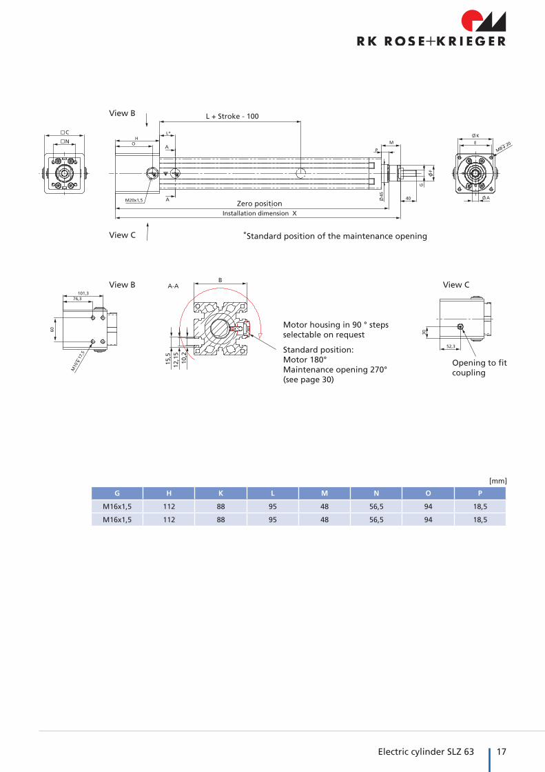
17Electric cylinder SLZ 63
G H K L M N O P
M16x1,5 112 88 95 48 56,5 94 18,5
M16x1,5 112 88 95 48 56,5 94 18,5
[mm]
A
A
L + Hub - 100
Einbaumaß XNullstellung
*Standard position of the maintenance opening
View B
View B
View C
View C
Motor housing in 90 ° steps selectable on request
Standard position:Motor 180°Maintenance opening 270°(see page 30)
Zero position
L + Stroke - 100
Installation dimension X
Opening to fit coupling

18 Electric cylinder SLZ 63 Technical data
Dimensions / ordering data
Electric cylinder SLZ 63 P with ball screw Control-Tec
Code No. Type Spindle A B C D E
TQ3_A1B1E3CAA_ _ _ _ SLZ 63 KG P PL KG 25x10 100 80 100 125 238
TQ3_A1B1E3BAA_ _ _ _ SLZ 63 KG P FL KG 25x25 100 80 100 125 238
�� Change of maintenance opening for SLZ 63 upon request
�� Motor housing in 90° steps upon request selectable (see page 30)
Order information:
Travel [mm]Installation
dimension X [mm]Weight [kg]
100 402 9,0
200 502 10,5
300 642 12,5
400 742 14,0
500 882 16,0
600 982 17,5
700 1122 19,5
800 1222 21,0
900 1362 23,0
1000 1462 24,5
Stroke [mm]e.g. 0 3 0 0
Degree of protection SLZ 63 KG P PL:1 = IP 543 = IP 65
Degree of protection SLZ 63 KG P FL:2 = IP 544 = IP 65

19Electric cylinder SLZ 63
F G H K L M N O P
40 M16x1,5 104 125 95 48 56,5 86 18,5
40 M16x1,5 104 125 95 48 56,5 86 18,5
[mm]
Motor housing in 90 ° steps selectable on request
Standard position:Motor 180°Maintenance opening 270°(see page 30)
L + Hub - 100
Einbaumaß X
Nullstellung
View B
M10
L + Hub - 100
Einbaumaß X
Nullstellung
L + Stroke - 100
Zero position
Installation dimension X

20 Electric cylinder SLZ 63
SLZ 63 Accessories / Fittings

21Electric cylinder SLZ 63

22 Electric cylinder SLZ 63
SLZ 63 Accessories / Fittings
Guide unit
Accessories / Fittings
F
Z
D
A
Q
A
AFy
Fz
F
Z
D
A
Q
A
AFy
Fz
* Mz = Fy x AMy = Fz x A
Available from march 2017
Code No. Type Stroke
QZD05_100
Guide unit for SLZ 63
100
QZD05_200 200
QZD05_300 300
QZD05_400 400
QZD05_500 500
QZD05_600 600
QZD05_700 700
QZD05_800 800
QZD05_900 900
QZD05_1000 1000
1 = Slide guide2 = Ball bearing guide
* Note:The moments Mz and My are the permissible dynamic loads; thestatistic loads are twice that.
VersionPermissible dynamic load Mass of guide units
Suitable for SLZ 63Mz (Nm) My (Nm) 0-stroke (kg) per 100 mm (kg)
Slide guide 60 54 4.6 0.5 Trapezoidal screw
Ball bearing guide 48 43 4.4 0.5 Ball screw
Scope of delivery: Guide unit, incl. fixing material
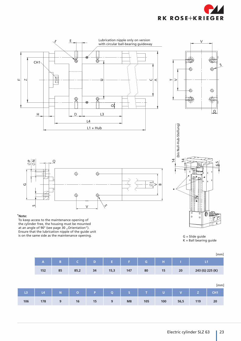
23Electric cylinder SLZ 63
A B C D E F G H I L1
152 85 85,2 34 15,3 147 80 15 20 243 (G) 225 (K)
L3 L4 N O P Q S T U V Z CH1
106 178 9 16 15 9 M8 105 100 56,5 119 20
[mm]
[mm]
* Note:To keep access to the maintenance opening of the cylinder free, the housing must be mounted at an angle of 90° (see page 30 „Orientation“).Ensure that the lubrication nipple of the guide unit is on the same side as the maintenance opening.
F
Z
D
A
Q
A
AFy
Fz
*
G = Slide guideK = Ball bearing guide
Lubrication nipple only on version with circular ball-bearing guideway
(bis
Nu
ll-H
ub
-Ste
llun
g)

24 Electric cylinder SLZ 63 Accessories / Fittings
Code No. Type
QZD050644 SLZ 63 Cevis M16x1,5
Clevis
Bearing block for clevis
Swivel head
Code No. Type
QZD050573 SLZ 63 Bearing block Ø16
Code No. Type
QZD050645 SLZ 63 Swivel head M16x1,5
SLZ 63 Accessories / Fittings
8°
8°
28
1521
Ø16
H7
64
M16x1,5
Ø42
25Electric cylinder SLZ 63
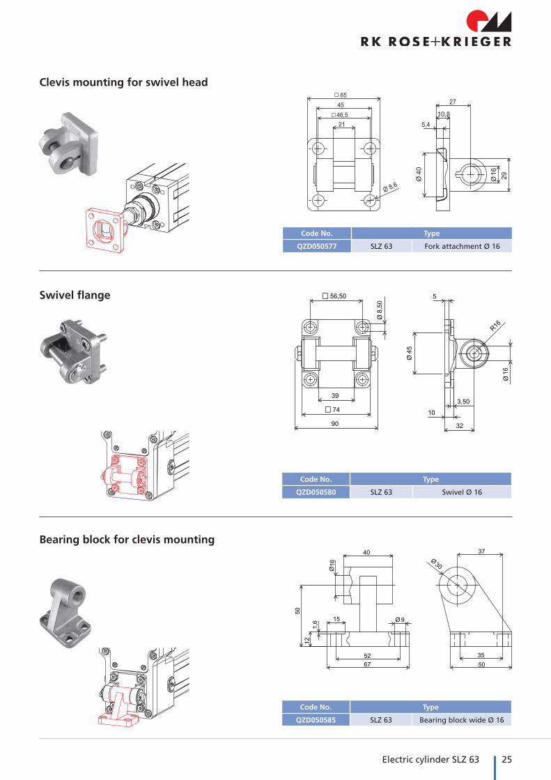
Code No. Type
QZD050577 SLZ 63 Fork attachment Ø 16
Clevis mounting for swivel head
Swivel flange
Bearing block for clevis mounting
Code No. Type
QZD050580 SLZ 63 Swivel Ø 16
Code No. Type
QZD050585 SLZ 63 Bearing block wide Ø 16

26 Electric cylinder SLZ 63 Accessories / Fittings
Trunnion support blocks
Code No. Type
QZD050646 Trunnion support blocks SLZ 63
QZD050647 Trunnion SLZ 63
Slot stone �� Slot stones facilitate the attach-ment of fittings to the cylinder.
�� They can be slid into the lateral slots (Type -N-) or swivelled into the slot from above (Type -R-).
Code No. Type F [N]
4006201 Slot stone -N- M5 4.000
4006203 Slot stone -N- M6 4.000
4026207 Slot stone -N- M5 4.000
4026203 Slot stone -N- M6 9.000
4026206 Slot stone -N- M8 9.000
4026221 Slot stone -R- M6 8.000
4026222 Slot stone -R- M8 8.000
Type -N- Type -R-
Code No. Type
QZD050589 Support blocks SLZ 63
Support blocks for trunnion mounting
SLZ 63 Accessories / Fittings
27Electric cylinder SLZ 63
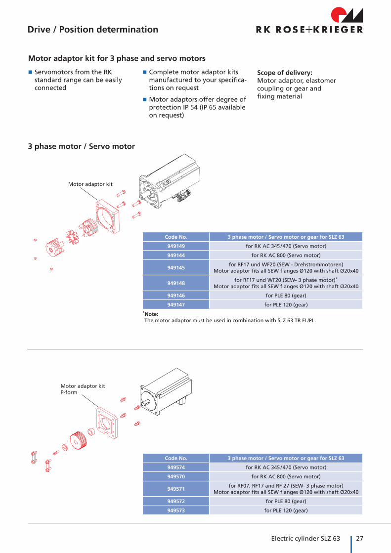
Motor adaptor kit for 3 phase and servo motors
Drive / Position determination
�� Servomotors from the RK standard range can be easily connected
�� Complete motor adaptor kits manufactured to your specifica-tions on request
�� Motor adaptors offer degree of protection IP 54 (IP 65 available on request)
Scope of delivery:Motor adaptor, elastomer coupling or gear and fixing material
Motor adaptor kitP-form
Code No. 3 phase motor / Servo motor or gear for SLZ 63
949574 for RK AC 345 / 470 (Servo motor)
949570 for RK AC 800 (Servo motor)
949571for RF07, RF17 and RF 27 (SEW- 3 phase motor)
Motor adaptor fits all SEW flanges Ø120 with shaft Ø20x40
949572 for PLE 80 (gear)
949573 for PLE 120 (gear)
Motor adaptor kit
3 phase motor / Servo motor
* Note:The motor adaptor must be used in combination with SLZ 63 TR FL/PL.
Code No. 3 phase motor / Servo motor or gear for SLZ 63
949149 for RK AC 345 / 470 (Servo motor)
949144 for RK AC 800 (Servo motor)
949145for RF17 und WF20 (SEW - Drehstrommotoren)
Motor adaptor fits all SEW flanges Ø120 with shaft Ø20x40
949148for RF17 und WF20 (SEW- 3 phase motor)*
Motor adaptor fits all SEW flanges Ø120 with shaft Ø20x40
949146 for PLE 80 (gear)
949147 for PLE 120 (gear)

28 Electric cylinder SLZ 63
Magnetic switch �� Signals from the magnetic switch can be collected and evaluated by a customer-provid-ed control unit (such as a PLC).
�� The switch can be retrofitted in the lateral slot (protected by a cover profile as standard)
�� Magnets are already integrated within the cylinder as standard.
25,3
55,
16,5
Magnetic switch
Extension for magnetic switch
Magnetic switch – Technical data
NC contact
Voltage 10-30 V DC
Current consumption < 10 mA
Output current Max. 100 mA
Output type PNP
Function indication LED
Ambient temperature -20°C to +70°C
Degree of protection IP 67
Code No. Type
QZD050600 Magnetic switch, NC contact, cable length 0.3 m
QZD050601 Extension for magnetic switch, cable length 5 m
SLZ 63 Accessories / Fittings
Accessories / Fittings

29Electric cylinder SLZ 63

30 Electric cylinder SLZ 63
Enquiry form
1.) What is the cylinder required to move? ..................................................................................................................................
...................................................................................................................................................................................................
2.) Orientation
3.) Max. lifting force [N]......................................... 4.) Static load [N] ........................
5.) Lifting speed [mm/s] ........................ 6.) Stroke length [mm] .....................................
7.) Type of fastening ............................................. 8.) Ambient temperature ........................ °C
9.) Operating voltage [V] ................................... 10.) Required protection class ......................... (standard IP54)
11.) Frequency converter operation planned
12.) Operating cycles = no. of double strokes (forwards and backwards movement)
per minute hour day average ........................ / max. ........................
13.) Radial forces [N] ...................................... 14.) No. of units required ................................ (avoid if possible)
15.) Is there a risk of personal injury if the drive fails? 16.) Compliance with any specific regulations required? (to avoid in any case)
......................................................................................... .........................................................................................
Submission of offer / date: ..............................................................................................................................................................
Remarks: ..........................................................................................................................................................................................
RK Rose+Krieger GmbH • Connecting and positioning systems • Postfach 1564 • 32375 Minden, Germany
Fax: +49 (0)571 9335-119Telephone: +49 (0)571 9335-0
E-mail: anfrage.vertrieb@rk- online.deCompany ........................................................................................... Cust. No. ................................................................................
Street ................................................................................................ City ........................................................................................
Telephone ......................................................................................... Fax .........................................................................................
Contact .............................................................................................. Dept. ......................................................................................
Remarks ............................................................................................................................................................................................
...........................................................................................................................................................................................................
�1 �2 �3 �4
• Motor 270° • Maintenance opening 270°
(only possible if maintenance opening is relocated)
• Motor 180° • Maintenance opening 270°
(Standard position)
• Motor 0° • Maintenance opening 270°
• Motor 90° • Maintenance opening 270°
0°
180°
90°270°

31Electric cylinder SLZ 63
Our product ranges
9Manual adjustment units
9Electric cylinders
9 Lifting columns
9 Linear axes
9 We can move loads for you of up to 3 t and up to 12 m dynamically, reliably and with great precision
LINEAR TECHNOLOGY
9 The tried and tested BLOCAN® aluminium assembly system
9 Sections from 20 mm to 320 mm for all applications
9 Connecting technology with an unsurpassed combination of flexibility and reliability
PROFILE TECHNOLOGY
9 Fittings for the secure clamp connection of round and square tubes
9 Elements made of aluminium, stainless steel and plastic
9 Sizes from 8 mm to 80 mm
CONNECTING TECHNOLOGY
9Machine frames
9Workstations
9Machine guards
9Multidimensional linear axis modules
9Complete drive solutions
MODULE TECHNOLOGY

EN 2
50 F
lyer
alar
m M
AR
10
30 1
5 00
07 0
9/20
16 P
rin
ted
in G
erm
any
FAX reply form
Company:
Contact partner:
Department:
Address:
Tel. + Fax:
E-mail:
Yes, I would like to know more about RK linear technology, please:
send me the Linear Technology catalogue
send me details of your product range in PDF format on a CD-ROM
contact me
Connecting and positioning systems
RK Rose+Krieger GmbHPostfach 15 6432375 Minden, GermanyTelephone: +49 5 71 93 35-0Fax: +49 5 71 93 35-119E-mail: [email protected]: www.rk-rose-krieger.com


![Topological Efiects on Minimum Weight Steiner Triangulationsdeloera/MISC/LA... · Topological Efiects on Minimum Weight Steiner Triangulations ... 19, 18, 20, 10] and higher dimensions[7,](https://static.documents.pub/doc/80x56/5e8fda2f67843537225cd76d/topological-eiects-on-minimum-weight-steiner-triangulations-deloeramiscla.jpg)


