Maximum stress of stiff elastic plate in uniform flow and due to jet impact A.A. Korobkin 1 , T.I. Khabakhpasheva 2 , S. Malenica 3 1 School of Mathematics, University of East Anglia, Norwich, UK, e-mail: [email protected]2 Lavrentyev Institute of Hydrodynamics, Novosobirsk, Russia e-mail: [email protected]3 Bureau Veritas, Marine & Offshore Division - Research Department, France, [email protected]The liquid jet impact onto a clamped elastic plate is investigated. The two-dimensional jet of con- stant thickness and with flat vertical front is initially advancing towards the elastic plate along a flat, rigid and horizontal plane at a constant uniform speed. The elastic plate of variable thickness is mounted perpendicular to the rigid plane. The maximum stress during the early impact stage is estimated for a given retardation time and a given relaxation time of the plate material. The stresses during the initial impact stage are compared with the static stresses in the plate placed in an equivalent uniform flow. It is shown that the static stresses are always smaller than the bending stresses during the early stage of impact for a given speed and thickness of the jet. This implies that if the stresses in the plate are smaller than the yield stress of the plate material with no plastic deformations in the plate occurring during the unsteady impact stage, then the plate behaves elastically after the impact and plastic deformations are not achieved. Approaching the plastic deformations is treated here as a damage to the plate. The maximum stress increases with the increase of the jet thickness. A critical value of the jet velocity, below which the plate is not damaged by the jet impact, is obtained for given characteristics of the plate. I. Introduction The two-dimensional problem of fluid impact onto a clamped elastic plate is considered. The flow region before impact is a semi-strip bounded from below by a rigid plane and above by the flat free surface. The front free surface of the flow region is vertical, see figures 1a and 1b.We distinguish two cases with the plate being longer than the jet thickness (figure 1a) and the plate shorter than the jet thickness (figure 1b). The fluid is advancing initially towards the elastic plate at a constant uniform speed. The elastic plate is clamped to the rigid bottom at its lower end. The upper end of the plate is free of stresses. The plate deflection is described by the Euler beam equation. We are concerned with the bending stresses in the plate caused by impact. In particular, we shall determine the maximum speed of the jet impact, at which the plate still behaves elastically with the bending stresses in the plate being below the value of the yield stress of the plate material. The problem is coupled: the plate deflection and the hydrodynamic loads acting on the plate are determined simultaneously. We consider elastic plates of high rigidity such that the plate deflection caused by plate interaction with the fluid is relatively small and the lowest period of the plate free vibration in the air is also small. The maximum stresses are achieved during an early stage of short duration. During the initial impact stage, see figures 1c and 1d, the problem is linearized and solved by the normal mode method at leading order. Later on both the plate deflection and the flow around the plate approach their steady states with the flow separating from the upper end of the plate and forming a cavity behind the plate, see figures 1e and 1f. The stresses in the plate at this later stage are determined by decoupled approach and used as reference stresses in the present analysis. 1 brought to you by CORE View metadata, citation and similar papers at core.ac.uk provided by University of East Anglia digital repository
Transcript
Maximum stress of stiff elastic plate in uniform flowand due to jet impact
A.A. Korobkin1, T.I. Khabakhpasheva2, S. Malenica3
1 School of Mathematics, University of East Anglia, Norwich, UK,e-mail: [email protected]
2 Lavrentyev Institute of Hydrodynamics, Novosobirsk, Russiae-mail: [email protected]
3 Bureau Veritas, Marine & Offshore Division - Research Department, France,
The liquid jet impact onto a clamped elastic plate is investigated. The two-dimensional jet of con-stant thickness and with flat vertical front is initially advancing towards the elastic plate along aflat, rigid and horizontal plane at a constant uniform speed. The elastic plate of variable thicknessis mounted perpendicular to the rigid plane. The maximum stress during the early impact stageis estimated for a given retardation time and a given relaxation time of the plate material. Thestresses during the initial impact stage are compared with the static stresses in the plate placedin an equivalent uniform flow. It is shown that the static stresses are always smaller than thebending stresses during the early stage of impact for a given speed and thickness of the jet. Thisimplies that if the stresses in the plate are smaller than the yield stress of the plate material withno plastic deformations in the plate occurring during the unsteady impact stage, then the platebehaves elastically after the impact and plastic deformations are not achieved. Approaching theplastic deformations is treated here as a damage to the plate. The maximum stress increases withthe increase of the jet thickness. A critical value of the jet velocity, below which the plate is notdamaged by the jet impact, is obtained for given characteristics of the plate.
I. Introduction
The two-dimensional problem of fluid impact onto a clamped elastic plate is considered. Theflow region before impact is a semi-strip bounded from below by a rigid plane and above by the flatfree surface. The front free surface of the flow region is vertical, see figures 1a and 1b.We distinguishtwo cases with the plate being longer than the jet thickness (figure 1a) and the plate shorter thanthe jet thickness (figure 1b). The fluid is advancing initially towards the elastic plate at a constantuniform speed. The elastic plate is clamped to the rigid bottom at its lower end. The upper end ofthe plate is free of stresses. The plate deflection is described by the Euler beam equation. We areconcerned with the bending stresses in the plate caused by impact. In particular, we shall determinethe maximum speed of the jet impact, at which the plate still behaves elastically with the bendingstresses in the plate being below the value of the yield stress of the plate material. The problemis coupled: the plate deflection and the hydrodynamic loads acting on the plate are determinedsimultaneously. We consider elastic plates of high rigidity such that the plate deflection caused byplate interaction with the fluid is relatively small and the lowest period of the plate free vibrationin the air is also small. The maximum stresses are achieved during an early stage of short duration.During the initial impact stage, see figures 1c and 1d, the problem is linearized and solved by thenormal mode method at leading order. Later on both the plate deflection and the flow around theplate approach their steady states with the flow separating from the upper end of the plate andforming a cavity behind the plate, see figures 1e and 1f. The stresses in the plate at this laterstage are determined by decoupled approach and used as reference stresses in the present analysis.
1
brought to you by COREView metadata, citation and similar papers at core.ac.uk
provided by University of East Anglia digital repository
Fig. 1 Jet impact onto elastic clamped plate: (a, b) positions of the plate and the liquid region beforeimpact, (c, d) sketches of the flows during the initial stage of impact, (e, f) sketches of the steady flows
during the later stage.
This study is motivated by the problem of violent sloshing in liquefied natural gas (LNG) tanksof NO96 type. NO96 membrane system is a cryogenic liner which includes two metallic membranesand two insulation layers1. The membranes are made of 500 mm wide and 0.7 mm thick stripsof a nickel-steel alloy. The strips of the primary membrane, which is in contact with the LNGcargo, are joined by welding their raised edges with a tongue between them (figure 2a). The tongue
Fig. 2 The tongue of NO96 system of length L and with the raised edges of length δL:
(a) sketch of the tongue and the raised edges, (b) dimensions of the NO96 system.
2
is made of the same alloy but it is 0.5 mm thick. It goes above the raised edges of the primarymembrane and also below the primary level. The tongues allow sliding the membrane on the top ofthe insulation layer avoiding shear stresses in the system. Also the transverse loads caused by LNGsloshing are reduced through deflections of the tongue and the raised edges. We shall determinecritical velocities of the LNG near a tongue, which may lead to plastic deformations of either raisededges of the primary membrane or the tongue itself, in uniform flow and during jet impact ontothe tongue. Jet-type flows can be generated by sloshing wave impact onto the tank wall near thetongue. The jet speed can be much greater than a typical speed of the main flow. This problem canbe also related to sloshing wave impact on corrugations of Mark-III containment system2. However,the Mark-III corrugations cannot be approximated by thin plates. Shallow-water sloshing in a 2Dtank with a typical elastic panel of Mark-III containment system was studied both experimentallyand numerically by Lugni et al.3 The walls of the tank were rigid with the elastic panel mountednear the equilibrium water level. The study was concerned with the flip-through type of sloshingimpact which is characterized by hydrodynamic loads of short duration and very high magnitude.
Experimental, theoretical and numerical studies of sloshing-induced impact loads on tank wallsof LNG vessels involve many complex physical phenomena such as phase transition, fluid com-pressibility and aeration. Smoothed Particle Hydrodynamics (SPH) simulations of liquid impacton complex structures like Mark-III and NO96 containment systems were performed by Oger et.al4. Several test cases were used to validate the developed SPH structural model, including the caseof deformable beam wedge impacting the free surface at very high speed. The full-scale sloshingexperiments using focused waves impacting on a fully instrumented LNG carrier NO96 membranecontainment panel are described by Brossest et. al5. These experiments led to new insights intosloshing impact and the influence of hydro-elasticity. The paper by Lafeber et. al6 shows that dif-ferent regimes of interaction between breaking waves and corrugated wall induce loads that can bepresented as combination of direct impact, building jet along the wall and compression/expansionof entrapped gas elementary loading processes. The configuration of the present study correspondsto the direct impact elementary process6.
At larger scale of order of few meters, the problem of this study corresponds to that oftsunami bore impact on coastal structures and interaction of dry-bed surges and broken waveswith buildings7,8. Some tsunamis may break offshore and arrive at the coast as a tsunami bore9
with almost uniform both depth and speed of the flow. Surge waves are also resulting from dambreaks. The profile of the bore front could be rather steep, see the free-surface elevation in figure3 of Wei et al.8, and can be approximated by a vertical front. The flows in surge waves and brokenwaves are very turbulent10 with significant amount of air entrained before the impact onto a struc-ture. The fluid near the wave front is aerated11,12. However, it was shown13 that the maximumstresses in an elastic wall impacted by a breaking wave are weakly dependent on the level of thefluid aeration.
The present model of jet impact onto vertical elastic plate is highly simplified in terms of theimpact conditions. In reality, the jet front is not parallel to the plate at impact instant (figure 3a),compressibility (figure 3b) and aeration of the fluid in the impact region (figure 3c), as well as thepresence of the air in between the plate and the approaching jet front (figure 3d), matter. Theseeffects make the hydrodynamic loading on the plate to be gradual in time and can be described,in terms of the maximum bending stress in the plate, by using a concept of retardation time,which characterizes the duration of the early transient stage. The idea behind the concept of theretardation time is that the complex problem of fluid impact onto an elastic plate in practicalsituations can be split into two: (1) the problem of jet impact onto a vertical elastic plate with thejet front being vertical and the retardation time given, (2) estimation of the retardation time fora particular situation. The concept of the retardation time is also related to the condition of the
3
Fig. 3 The jet impact onto a vertical elastic plate with (a) the jet front not parallel to the plate,(b) compressible liquid in the jet, (c) aerated front of the jet, (d) presence of the air in between the
plate and the approaching jet front.
plate failure by the jet impact. In the present model, it is required that the bending stress in theplate should stay above the yield stress value for a certain time before plastic deformations start.Note that we assume here that the elastic model of the plate can still be used for stresses near andslightly higher than the yield stress value.
The problem of a clamped elastic plate in a jet flow is formulated in section II. The list ofnomenclature used in the paper is placed just after References. The elastic plate is of non-constantthickness. Only the plates with piecewise constant thickness are simulated but the theoreticalmodel and the algorithm of its analysis are valid for more complicated structures with almost flatsurface. The stationary stresses in the plate with the flow separation at the plate edge are estimatedin section III within the decoupled approach. These stresses are used as the reference stresses forthe jet impact problem in section IV within the coupled theory of hydroelasticity. Calculationsare performed for the parameters of the tongue shown in figure 2. The obtained numerical resultsare presented in section V. It is shown that the steady-state stresses are much smaller than themaximum stress achieved during the impact stage. The conclusions are drawn in section VI.We conclude, in particular, that if an elastic plate has survived the impact stage without plasticdeformations, then it will not be damaged in the subsequent steady flow.
II. Formulation of the problem
The two-dimensional interaction between a fluid jet of thickness H and an elastic plate of lengthL is considered in the Cartesian coordinate system x, y with the origin at the clamped edge of theplate, see figure 1a, b. The fluid moves towards the plate at a uniform speed V . The fluid occupiesthe semi-infinite region, x > 0, 0 < y < H, at the time of impact, t = 0. The fluid is assumedincompressible and inviscid. Gravity and surface tension effects are neglected. The presence ofair between the plate and the approaching vertical front of the jet is not included in the presentanalysis. The elastic plate of variable thickness h(y), where 0 < y < L, is clamped to the flatbottom, y = 0. Another end of the plate is free of stresses and shear forces. The plate is verticaland perpendicular to the direction of the flow before impact. We assume that the plate deflectionfrom its initial position is small even at the beginning of the plastic deformations in the plate.
4
Pressure-impulse theory and fully coupled approach are used to estimate the bending stresses inthe plate during the early stage of impact, duration of which is of order of the main period of thefree vibration of the equivalent elastic beam. Decoupled approach is used to evaluate the staticstresses in the plate at large times.
The jet thickness H can be smaller or greater than the plate length L. The jet flow can be causedby liquid impact onto a rigid wall, by breaking wave impact onto a vertical wall, or it can model along wave propagating towards a vertical structure along a dry bed. In practical problems, the jetis of variable thickness and the jet (wave) front is not parallel to the wall at the time of impact.However, the present analysis still can be used if the jet thickness varies slowly with the distancefrom the wall and the jet speed is relatively large. The assumptions of the vertical wave front andincompressible liquid overestimate contributions of the higher modes of the plate vibration causedby the jet impact. To account for realistic conditions of the jet/wave impact, a retardation time Tris introduced below. The retardation time accounts for the fact that the hydrodynamic loads arenot applied instantly to the plate due to some physical effects (see figure 3), which are not includedin the present simplified model. The retardation time Tr may also account for the fact that theplastic deformations of the plate material cannot start instantly, when the local stress achieves theyield stress value.
We shall evaluate the bending stresses in the plate caused by the jet impact and to comparethem with the yield stress σY of the plate material. If the maximum of the induced stresses exceedsthe yield stress during a time interval (t − Tr/2, t + Tr/2), then the plate is said be damagedby impact at time instant t. Here Tr is the retardation time of the plate material. In this caseplastic deformations in the plate occur and the plate cannot return to its initial shape after thehydrodynamics loads are released. This condition of the plate damage is used in this study in theintegral sense: the plate is damaged if the elastic stress averaged over time intervals of duration Trexceed the yield stress σY of the plate material.
Both the short-term and long-term interactions of the plate with the jet flow are studied. In thelong-term analysis, the jet flow and the plate deflection are stationary, the hydrodynamic loads aremuch smaller than the loads during the initial impact stage but they last longer. In the short-termanalysis valid for the early stage, duration of which is of the order of the period of the first modeof the free plate vibration, hydrodynamic loads are impulsive and the plate is more likely to bedamaged if the jet speed is large enough. It will be shown in the present study that, if the platehas not been damaged during the impact stage, it will not be damaged in the steady jet flow.
The plate deflection, w(y, t), is governed by the linear Euler beam equation
ρph(y)∂2w
∂t2+∂Q
∂y= p(−w(y, t), y, t),
∂M
∂y= Q(y, t), EI(y)
∂2w
∂y2= M(y, t) (0 < y < L), (1)
where ρp is the density of the plate material, Q(y, t) is the shear force, M(y, t) is the bendingmoment, E is the Young modulus of the plate material, I(y) = h3(y)/12 is the moment of theinertia of the plate sections, the plate deflection, w(y, t), is positive in the direction of the flow.The plate is clamped at the lower edge and free of stresses at the upper end:
The hydrodynamic pressure, p(x, y, t), is given by the Bernoulli equation
p = −ρ(∂ϕ∂t
+1
2|~u|2 − 1
2V 2), ~u(x, y, t) = ∇ϕ (3)
5
in the flow region Ω(t), where ϕ(x, y, t) is the velocity potential and ~u(x, y, t) is the velocity fieldof the flow. The velocity potential satisfies the Laplace equation, ∇2ϕ = 0, in the flow region, thekinematic boundary condition and the dynamic boundary condition, p = 0, on the free surface ofthe fluid region, the body boundary condition, ϕx+wyϕy +wt = 0, on the wet surface of the plate,x = −w(y, t) + h(y)/2, the condition on the bottom, ϕy = 0, where y = 0 and x > 0, the conditionat infinity, ϕ ∼ −V x as x → +∞, and the initial condition ϕ = −V x in the initial flow regionΩ(0−) before impact, t = 0−. The formulated problem is coupled: the plate deflection depends onthe hydrodynamic pressure through the beam equation (1) and the pressure depends on the platedeflection through the boundary condition on the plate surface. The stresses on the surface of theplate are given by
where tensile stresses are positive. The condition that the plate is not damaged during an initialtime interval (0, Tf ) is formulated as
max0<t<Tf
max0≤y<L
∣∣∣ 1
Tr
∫ t+Tr/2
t−Tr/2σ(y, τ)dτ
∣∣∣ < σY . (5)
The condition (5) is a simplified version of the failure criterion by Petrov and Utkin14. Theyargued that any known criteria of quasi-static fracture transferred directly to dynamic problems”would be physically incorrect”14. They wrote ”It should be mentioned that within the limits ofthe force fracture mechanics, a relatively high instantaneous value of the acting force should leadto failure. However, the dynamic failure is accompanied by the change in the extent of motion ofthe particles adjacent to the fracture area and a force pulse is required for failure. For example,in interpreting failure separation of two ”atoms”15, it is essential to take into account the inertia.To separate the two elements it is not sufficient to apply the single force; this force must act fora relatively long period of time.” In the criterion of dynamic failure introduced in14, stressesare averaged over a time Tr, which is ”the time of transfer of the interaction from one structuralelement to another,” and over a small structural element. In the condition (5), we do not distinguishstructural elements and we do not average the bending stress σ(y, t) over such elements as it isdone in14.
To model the tongue and raised edges of NO96 membrane system, we consider the plate ofpiecewise constant thickness, h(y) = h1, where 0 < y < δL, and h(y) = µh1, where δL < y < L,see figure 2. Here 0 < δ < 1 and 0 < µ < 1. The plate of constant thickness is obtained with eitherδ = 1 or µ = 1. For NO96 membrane system, µ = 5/19 and δ = 4/7.
III. Decoupled problem of plate deflection in uniform flow
The stresses in the elastic plate during the early impact stage are expected to be high due toimpulsive hydrodynamic loading of large magnitude. The hydrodynamic loads after the impactstage are smaller but they last longer. We do not consider here periodic vibrations of the plate ina steady jet. It is possible that the clamped plate has survived the impact loads without plasticdeformations, but it is deformed plastically later on, when the loads are stationary. In order toinvestigate if it is possible or not, we consider the steady problem of elastic clamped plate placed insteady uniform flow. This problem can be considered as the jet/plate interaction problem for infinitethickness of the jet. A reason for such an approximation comes from the analysis of hydrodynamic
6
force acting on a rigid plate in steady jet flow. It is shown by Birkhoff, Plesset and Simmons16,17
that the total force acting on the plate is weakly dependent on the jet thickness H for H > L.We also assume that the deflection of the elastic plate in a steady uniform flow is small and thehydrodynamic pressures along the plate can be approximated by their values calculated for anequivalent rigid plate. In the dimensional variables, the static pressure distribution along the plate,x = 0, 0 < y < L, is given in parametric form by the formulae16:
p(0, y) =1
2ρV 2
(1− tan2(θ/2)
), y =
2L
4 + π
(2 sin θ + sin θ cos θ + θ
), (6)
where the parameter θ varies from zero at the bottom, y = 0, to π/2 at the plate edge. Equations(6) provide
p(0, y)dy =4ρV 2L
4 + πcos2 θdθ. (7)
Integrating the static beam equation, dQ/dy = p(0, y), see the first equation in (1), in y using(7) and the edge conditions (2), we find the shear force distribution along the plate:
Q(y) =4ρV 2L
4 + π
(1
4sin(2θ) +
1
2θ − π
4
), (8)
where the vertical coordinate y(θ) is given by (6). Note that p(0, y) ≥ 0 and, therefore, Q(y) is amonotonically increasing function with Q(L) = 0 and Q(0) = −πρV 2L/(4 + π).
The second equation in (1) in static case, dM/dy = Q(y), provides the distribution of thebending moment along the plate. Here Q(y) ≤ 0 and, therefore, M(y) is a monotonically decreasingfunction with M(L) = 0. Integrating the equation for the bending moment and using (8) and (2),we obtain
M(y) = ρV 2L2f(θ), (9)
f(θ) =4
(4 + π)2
1
2
(θ − π
2
)(sin(2θ) + 4 sin θ + θ − π
2
)− 1
2cos4 θ − 2
3cos3 θ +
1
2cos2 θ + 2 cos θ
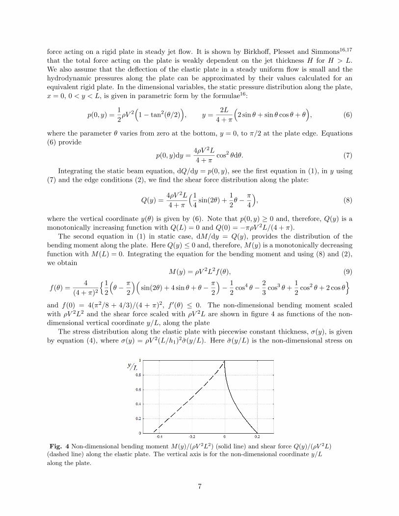
and f(0) = 4(π2/8 + 4/3)/(4 + π)2, f ′(θ) ≤ 0. The non-dimensional bending moment scaledwith ρV 2L2 and the shear force scaled with ρV 2L are shown in figure 4 as functions of the non-dimensional vertical coordinate y/L, along the plate
The stress distribution along the elastic plate with piecewise constant thickness, σ(y), is givenby equation (4), where σ(y) = ρV 2(L/h1)
2σ(y/L). Here σ(y/L) is the non-dimensional stress on
Fig. 4 Non-dimensional bending moment M(y)/(ρV 2L2) (solid line) and shear force Q(y)/(ρV 2L)(dashed line) along the elastic plate. The vertical axis is for the non-dimensional coordinate y/L
along the plate.
7
Fig. 5 (a) The function µ = µe(δ) (thick line) and µ = 1− δ (thin line). (b) The non-dimensional bending
stress on the surface of the plate, σ(y/L), as a function of the non-dimensional vertical coordinate y/L for
uniform plate, µ = 1, (thick line), tongue of NO96 system with µ = 5/19 and δ = 4/7 (thin line, diamond
marker in (a)), and a tongue with µ = 0.6 and δ = 4/7 (dashed line, cross marker in (a)).
the surface of the plate, σ(y/L) = 6f(θ), where 0 < y/L < δ, and σ(y/L) = 6f(θ)/µ2, whereδ < y/L < 1. Note that σ(y/L) is discontinuous at y = Lδ. The function f(θ) is monotonicallydecreasing. Therefore, the maximum static stress σs,max is equal to either σ(0) or σ(δ+0) dependingon values of δ and µ. The curve µ = µe(δ), on which σ(0) = σ(δ+0), is determined by the equationµ2 = f(θδ)/f(0), where y = Lδ at θ = θδ in (6). This curve is shown in figure 5a. It is seenthat µe(δ) ≈ 1 − δ. Then σs,max = σ(δ + 0) for 0 < µ < µe(δ) and σs,max = σ(0) for µ > µe(δ).The values δ = 4/7 and µ = 5/19 corresponding to the tongue of NO96 membrane system, are shownin figure 5a of the (µ, δ)− plane by diamond and the values δ = 4/7 and µ = 0.6 corresponding toa thicker tongue are shown by cross. The stress distributions for these tongues and for the plateof constant thickness, µ = 1, are shown in figure 5b. It is seen that the reduction of the platethickness in δ < y/L < 1 increases the stresses in this interval.
The maximum static stress σs,max is independent of the plate rigidity and is proportional tothe flow speed squared. The maximum bending stress σs,max exceeds the yield stress of the tonguematerial, σY , for the speed of the flow, V , such than
V >h1µ
L
( σY6ρf(θδ)
)12, (10)
where 0 < µ < µe(δ), and
V >h1L
( σY6ρf(0)
)12, (11)
where µ > µe(δ). Inequality (10) should be used for the tongue of the NO96 membrane system.This inequality provides that the maximum stress in the NO96 tongue exceeds the yield stress,σY = 430 MPa, of the tongue material and the tongue is deformed plastically when the speed ofthe uniform flow of water, ρ = 1000 kg m−3, exceeds 22 m/s. For the flow of the liquified naturalgas with density ρ = 468.1 kg m−3, the flow speed starting from which the tongue is deformedplastically is equal to 32 m/s. The LNG flow speed starting from which the tongue is deformedplastically at the clamped end, y = 0, is equal to 47 m/s.
The obtained critical values of the uniform flow speed are high and difficult to be achieved inpractical conditions of sloshing. The corresponding critical speed of an impulsive flow, startingfrom which a tongue is deformed plastically, is much smaller then the static value. The criticalspeed of jet impact on a tongue is estimated below.
8
IV. Coupled problem of jet impact onto clamped elastic plate
The initial stage of jet impact onto an elastic plate of variable thickness, see figure 1a and1b, is considered in non-dimensional variables. We use the same notations for the non-dimensionalvariables but with tilde. The plate length L is taken as the length scale, the product V L as the scaleof the velocity potential, ρLV/T as the scale of the hydrodynamic pressure during the impact stage,where ρ is the fluid density, and V T as the scale of the plate deflection. Here T = 2
√3L2/(h1cp)
is the time scale, cp = (E/ρp)12 is the so-called bar velocity, E is the Young modulus and ρp is the
density of the plate material. The time-scale T is proportional to the period of the first mode of thefree vibration in air of the plate of constant thickness h1. For the NO96 tongue with E = 140×109
Pa and ρp = 7800 kg m−3, we find cp = 4236.6 m/s and T = 5.27× 10⁻⁴ s.There are five non-dimensional parameters in the jet impact problem. The parameter ε = V T/L
is the ratio of the fluid displacement, V T , during the initial stage and the length scale L. Thisparameter is assumed small, ε 1, in the present analysis. This implies that the analysis is validfor impact speeds much smaller than cph1/L. This gives V 230 m/s for the NO96 tongue. Thesmall parameter ε can be considered as a parameter of linearization. The boundary conditions of thehydrodynamic part of the coupled jet impact problem can be linearized at leading order as ε→ 0 andimposed on the positions of the liquid boundaries just before the impact, t = 0−. In particular, thenon-linear Bernoulli equation in the non-dimensional variables, p(x, y, t) = −ϕt + ε(ϕx − 1
2 |∇ϕ|2),
where ϕ = −V x + V Lϕ(x, y, t) is the velocity potential of the flow, can be linearized for smallε giving p(x, y, t) = −ϕt at leading order. The non-linear terms in the equations of motions andboundary conditions can be approximately neglected during the early stage of impact, if the impactvelocity V is not very high.
The plate response to the jet impact strongly depends on the jet thickness. This effects isdescribed by the non-dimensional parameter γ = H/L, where 0 < γ < ∞. If γ < 1, then thehydrodynamic pressure is applied only along the wetted part of the elastic plate, 0 < y < γ. Thirdnon-dimensional parameter α = ρL/(ρph1) indicates importance of the added mass of the plate,which is proportional to the product ρL, compared to the structural mass ρph1 per unit length ofthe plate. The fourth parameter, τ , is the non-dimensional retardation time of the plate material,τ = Tr/T . The fifth parameter, τD, is a non-dimensional stress relaxation time which describesstructural damping of the elastic plate within the Kelvin-Voigt internal damping model18. Withinthis model the second term in the Euler beam equation (1) is changed to (1 + τDT∂/∂t)(∂Q/∂y).This model of structural damping is ”not adequate to completely represent the behaviour of realmaterial”18. More complicated models of damping combining the simple Kelvin-Voigt and Maxwellmodels with several parameters can describe accurately responses of actual materials18. In thispaper we use the simplest model of structural damping having in mind that the numerical algorithmdeveloped below is flexible and can potentially accommodate any linear damping model. In thepresent analysis, α = O(1) and both τ and τD are small. For the NO96 tongue and LNG, we haveα = 1.1055.
Initial stage of the impact with t = O(1) is considered. The bending stresses in the plate (4)increase during the first quarter of the first period of the plate vibration in contact with the fluid,T1/4, which is estimated as T1/4 ∼ 2
πα12T , and oscillate thereafter with decreasing in time amplitude
owing to the structural damping of the plate. For the NO96 tongue, we have T1/4 ∼ 3.5× 10⁻⁴ s.During this early stage the plate deflection and the flow caused by impact are described in the
non-dimensional variables by equations19,20,21 (tilde is dropped below)
h(y)∂2w
∂t2+
∂2
∂y2
(h3(y)
∂2w
∂y2
)= αp(0, y, t) (0 < y < 1), (12)
9
w(0, t) =∂w
∂y(0, t) = 0,
∂2w
∂y2(1, t) =
∂3w
∂y3(1, t) = 0, w(y, 0) = 0 (13)
∇2ϕ = 0, p = −ϕt (x > 0, 0 < y < γ), (14)
ϕy(x, 0, t) = 0, ϕ(x, γ, t) = 0 (x > 0), (15)
ϕx(0, y, t) = χ(t)− wt(y, t) (0 < y < 1), (16)
ϕ→ 0 (x→∞), (17)
where χ(t) is the Heaviside step function, χ(t) = 0, where t < 0, and χ(t) = 1, where t > 0, andthe plate thickness h(y) in the non-dimensional variables is equal to 1, where 0 < y < δ, and equalto µ, where δ < y < 1. If γ > 1, then there is also the condition on the vertical part of the freesurface above the plate,
ϕ(0, y, t) = 0 (1 < y < γ). (18)
Within the Kelvin-Voigt damping model18, equation (12) reads
h(y)∂2w
∂t2+(
1 + τD∂
∂t
) ∂2∂y2
(h3(y)
∂2w
∂y2
)= αp(0, y, t) (0 < y < 1) (19)
The distribution of the non-dimensional stress along the right-hand surface of the plate is given by(4) and (1) as
σ(y, t) = h(y)∂2w
∂y2(20)
with the scale√
3ρpcpV . The structural problem without damping, (12) and (13), and the hydro-dynamic problem (14) - (18) for γ > 1 are depicted in Figure 6.
Fig. 6 The structural problem without damping and the hydrodynamic problem for γ > 1 depicted
together with the notations of the problems.
10
Fig. 7 Shapes of the first three normal modes (a) constant plate thickness, δ = 1, (b) NO96 tongue with
δ = 4/7 and µ = 5/19. Solid lines are for the first modes, dashed lines are for the second and the dotted
lines are for the third modes.
The problem (12)-(20) is coupled. The hydrodynamic loads on the plate depend on the velocityof the plate deflection through the body boundary condition (16).
The jet impact problem is solved by the normal-mode method19−22. The plate deflection w(y, t)within this method is sought in the form
w(y, t) =∞∑n=1
an(t)ψn(y), (21)
where an(t) are unknown principal coordinates of the plate deflection and ψn(y) are the non-trivialsolutions of the homogeneous boundary-value problem
d2
dy2
(h3(y)
d2ψndy2
)= λ4nh(y)ψn(y) (0 < y < 1), (22)
ψn(0) =dψndy
(0) = 0,d2ψndy2
(1) =d3ψndy3
(1) = 0, (23)
and λn are the corresponding eigenvalues. Moreover, the eigenfunctions ψn(y) satisfy the orthogo-nality condition ∫ 1
0h(y)ψn(y)ψm(y)dy = δnm, (24)
where δnm = 0 for n 6= m and δnn = 1 (see Appendix B). In the case of piecewise constant thicknessof the plate, the modes ψn(y) and their first derivatives are continuous at y = δ. The second andthird derivatives at this point are related by µ3ψ
′′n(δ+0) = ψ
′′n(δ−0) and µ3ψ
′′′n (δ+0) = ψ
′′′n (δ−0).
The first three normal modes are shown in Figure 7 for the plate of constant thickness and theNO96 tongue.
Equations (14)-(17) and the series (21) lead to the following decomposition of the velocitypotential
ϕ(x, y, t) = ϕ0(x, y)χ(t)−∞∑n=1
an(t)ϕn(x, y), (25)
where ϕn(x, y), n ≥ 0, are solutions of the boundary problem
with ψ0(y) = 1. The mixed boundary value problem (26) is solved in Appendix A by the methodof separating variables for γ < 1 and by the theory of analytical functions for γ > 1 with analytictreatment of the flow velocity singularity at the point x = 0, y = 1, where the boundary conditionchanges its type.
Substituting (21) and (25) in the beam equation (12), multiplying both sides of the equationby ψm(y), m > 1, integrating both sides of the equation in y from y = 0 to y = 1, and using theorthogonality condition (24), we arrive at the infinite system of ordinary differential equations withrespect to the principal coordinates of the plate deflection,
am + λ4mam = α
∫ 1
0p(0, y, t)ψm(y)dy, (27)∫ 1
0p(0, y, t)ψm(y)dy = − d
dt
∫ 1
0ϕ(0, y, t)ψm(y)dy = − d
dt
(− fmχ(t) +
∞∑n=1
Mnman
),
where
fm = −∫ 1
0ϕ0(0, y)ψm(y)dy, Mnm = −
∫ 1
0ϕn(0, y)ψm(y)dy.
Green’s second identity gives that the matrix M with the elements Mnm is symmetric. The system(27) can be written in the form
T , ~f = (f1, f2, f3, ....)T , I is the unit matrix and D is
the diagonal matrix, D = diag−λ41,−λ42, ..... The initial conditions for the system (28) are
~a(+0) = 0, ~b(+0) = 0. (29)
Note that the velocity of the plate at the impact time instant is not equal to zero,
d~a
dt(+0) = α(I + αM)−1 ~f 6= 0.
Within the Kelvin-Voigt damping model, see equation (19), the system of differential equations(28) is changed to
d~a
dt= (I + αM)−1(~b+ α~fχ(t) + τDD~a),
d~b
dt= D~a. (30)
In order to use the condition of the plate damage (5), it is convenient to introduce the non-dimensional deflection < w > (y, t) averaged over the time interval of duration τ , see condition(5),
< w > (y, t) =1
τ
∫ t+τ/2
t−τ/2w(y, t0)dt0. (31)
12
Then the condition (5) reads
max0<t<Tf/T
max0<y<1
| < σ > (y, t)| < σY /(√
3ρpcpV ), (32)
where the averaged in time deflection, < w > (y, t), and the averaged in time stress, < σ > (y, t),are related by (20). The averaged principal coordinates < an > (t) satisfy the system (28) withoutdamping or (30) with damping, where the function χ(t) is changed to χ(t) with χ(t) = 0,wheret < −τ/2, χ(t) = t/τ + 1/2, where −τ/2 < t < τ/2, and χ(t) = 1, where t > τ/2. It is seen thatthe averaging procedure is equivalent to smoothing the impact velocity by introducing the initialinterval of short duration τ , during which the velocity increases linearly from zero to the designedconstant value. The initial conditions for the averaged deflection < w > (y, t), where t > τ/2, are
< ~a > (−τ/2) = 0, < ~b > (−τ/2) = 0.
Denoting the left-hand side in (32) by C(τ, τD, γ), we conclude that the material of the platebehaves plastically during the jet impact on it, when the speed of the jet is greater than
V >Vp
C(τ, τD, γ), Vp =
σY√3ρpcp
. (33)
For the NO96 tongue, we have Vp ≈ 7.5 m/s. The critical velocity of the jet, Vp/C, startingfrom which the plate behaves plastically during impact, can be estimated once we know the max-imum stress in the plate, C(τ, τD, γ), which depends on the non-dimensional jet thickness γ, non-dimensional retardation time τ and the non-dimensional stress relaxation time τD.
V. Numerical results and their discussion
The linearized problem of jet impact onto clamped elastic plate is studied numerically for theNO96 tongue. Calculations of the integrals fm and Mnm in (27) are detailed in the Appendix A.The infinite systems (28) and (30), as well as the corresponding systems for the averaged deflectionwith χ(t) changed to χ(t), are truncated and integrated by the Runge-Kutta method of fourthorder with corresponding initial conditions. Calculations are performed with Nmod = 3, 5, 10, 15elastic modes in (21). The step of integration ∆t is equal to 1/10 of the non-dimensional periodof the highest retained mode with number Nmod. The stress distributions along the plate, theevolutions of bending stresses at critical points of the plate and the maximum non-dimensionalstress C(τ, τD, γ) as a function of the non-dimensional jet thickness γ, non-dimensional retardationtime τ and the non-dimensional stress relaxation time τD are studied for the NO96 tongue andLNG jet. The density of the jet fluid appears only in the parameter α, see equation (12). Changingthe LNG to water, we need to change α from 1.1 to 2.36.
The non-dimensional stress σ(δ+0, t) at the place, where the tongue thickness abruptly changes,as a function of time for γ = 1
2 and γ = 2, is shown in figures 8(a), left and right respectively.The stress has been computed with Nmod = 3 and 10 in the interval 0 < t < 1.75. The figures8(b) depict the bending stress at the lowest point of the plate, y = 0, as a function of time t. Itis seen that the stresses at y = 0 are smaller than at y = δ + 0 for both values of γ. The stressescan be decomposed in the ”slow-varying” parts, which are represented by the lowest three modes,and the ”high-frequency” perturbations. The stress σ(δ + 0, t) computed with three modes peaksat t ≈ 0.55 for both values of γ. The stresses and deflections along the plate at t = 0.55 areshown in figures 8(c) and 8(d) respectively for γ = 1
2 and γ = 2. It is seen that the distributions
13
Fig. 8 The non-dimensional bending stresses and deflections calculated for τ = 0 and τD = 0 withthree (thick solid lines) and ten (thin solid lines) modes retained in the series representation of the platedeflection (21) for the non-dimensional jet thickness γ = 1
2 (left) and γ = 2 (right).(a) The non-dimensional bending stress σ(δ + 0, t) at the boundary between the raised edge and thetongue, y = δ + 0, as a function of the non-dimensional time t,(b) The non-dimensional bending stress σ(0, t) at the clamped end of the plate y = 0, as a function ofthe non-dimensional time t,(c) The distribution of the bending stress along the tongue at t = 0.55 computed with three and tenelastic modes,
(d) The plate deflection along the tongue at t = 0.55 computed with three and ten elastic modes.
14
along the plate are rather smooth in contrast to the stress evolution in time. The contributionsof the higher modes are stronger for narrow jets, see left figures 8(c) and 8(d) for γ = 1
2 , than forthick jets. However, even for γ > 1, the convergence in terms of the number of modes is observedonly for the deflections, see right figure 8(d), but not for the stresses. The stresses become biggerwith the increase of the number of modes. It is clear does the series for bending stress obtainedfrom (21) converge theoretically but it does not converge practically. Therefore, the values of theretardation time Tr and/or stress relaxation time τD are important to estimate the bending stressesby the present simplified model.
The present model of jet impact onto elastic plate is simplified in terms of the impact conditions.In reality, the jet front is not parallel to the plate23 at impact instant (figure 3(a)), compressibility24
(figure 3(b)) and aeration12,13 (figure 3(c)) of the fluid in the impact region matter, as well as thepresence of the air10,11,22 in between the plate and the approaching jet front (figure 3(d)). Theseeffects make the hydrodynamic loading on the plate to be gradual in time and can be describedby using the concept of retardation time, Tr. For example, for the NO96 tongue and the jetof compressible water with the sound speed in water c0 = 1500 m/s, the retardation time canbe estimated as the time needed for the sound wave to travel from the upper edge of the plateto the bottom, Tr = L/c0 ≈ 2.5 × 10⁻⁵ s, which gives the non-dimensional retardation timeτ = Tr/T ≈ 0.05. The effect of the retardation time on the bending stress at y = δ + 0 is shownin figure 9 for γ = 1
2 (left) and γ = 2 (right) with the non-dimensions retardation time τ = 0.075and τ = 0.05. The figure 9 shows that even small values of the non-dimensional retardation timesignificantly reduce the contributions of the higher modes to the bending stresses. In order toexplain such a significant effect of retardation time on bending stresses, we compute the maximumbending stresses by (32) for different values of τ . The figure 10 shows that the maximum stress inthe NO96 tongue does not vary significantly for τ > 0.05. The results of calculations are shown infigure 10a for three, five and ten modes. It is clear that the maximum stress is weakly dependent onthe number of modes for τ > 0.05. This fact is explained in figure 10b, where the non-dimensionalperiods, Tn, of the dry elastic modes, ψn(y), governed by equations (22) and (23), are depicted. Theperiods Tn are shown by diamonds for the NO96 tongue (µ < 1) and by crosses for the equivalenttongue of constant thickness (µ = 1) for n ≥ 4. The first four non-dimensional periods of the NO96tongue are: T1 ≈ 1.51, T2 ≈ 0.59, T3 ≈ 0.19, T4 ≈ 0.1, and the periods of the tongue with constantthickness, which is the same tongue as the NO96 one but with µ = 1, are: T1 ≈ 1.79, T2 ≈ 0.29,T3 ≈ 0.1, T4 ≈ 0.05. The figure 10b shows that the retardation time τ = 0.05 is greater than theperiods of elastic modes starting from n = 5 for the NO96 tongue. Then the modes starting fromthe fifth one can be excluded from calculations for such a value of the retardation time. However,for the tongue of constant thickness (crosses in figure 10b) the required number of modes to retainis six. Therefore, higher modes are stronger pronounced for the tongue of constant thickness thanfor the tongue of variable thickness.
The effect of structural damping on the evolution of the bending stresses is depicted in figure11. The non-dimensional relaxation time τD is equal to 0.01 and 0.001 in these calculations withten elastic modes. It is clear that structural damping reduces the contributions of the higher modesin the bending stresses but also reduces the magnitudes of the stresses with time. On the otherhand, reduction of the first peak of the stress evolution is not significant. We can say that smallstructural damping does not affect the maximum stress in the elastic plate during jet impact on it.
15
Fig. 9 The bending stress at y = δ + 0 computed with ten elastic modes and τ = 0 (thin line),
Fig. 10 (a) The maximum bending stress given by the left-hand side of equation (32) as a function ofthe non-dimensional retardation time τ for the non-dimensional jet thickness γ = 1
2 and γ = 2.The stresses are calculated with three (crosses), five (diamonds) and ten (squares) modes.(b) The non-dimensional periods, Tn, of the dry elastic modes, ψn(y), as functions of the number n for
the NO96 tongue (diamonds) and the same tongue but of constant thickness, µ = 1, (crosses).
Fig. 11 Time evolutions of the non-dimensional stress at the point y = δ+0 calculated with ten modeswithout effects of damping and retardation (thin lines) and with account for damping with τD = 0.001
(thick lines) and τD = 0.01 (dashed lines).
16
Fig. 12 The maximum values of the non-dimensional bending stresses in the NO96 tongue at y = 0and y = δ + 0 in the time interval 0 < t < 2 as functions of the non-dimensional jet thickness γ cal-culated with four modes and τ = 0 (solid lines), with ten modes and τ = 0.075 (dotted lines), and forthe NO96 tongue of constant thickness, µ = 1, with ten modes and τ = 0.075 (dashed line). Note thatthe maximum stress given by the left-hand side of (5) is achieved at y = δ + 0 for the NO96 tongue and
at y = 0 for the equivalent plate of constant thickness.
The maximum non-dimensional stresses in the NO96 tongue of variable thickness and theequivalent tongue of the constant thickness (µ = 1) are shown in figure 12 as functions of thenon-dimensional jet thickness γ. The maximum averaged stress is defined by the left-hand sideof (5). In calculations, Tf = 2T , the step along the plate is smaller than 0.05 in both intervals0 ≤ y ≤ δ and δ ≤ y < 1, the step in time is 0.01 in the non-dimensional variables. Note that thebending stress is discontinuous at y = δ, see figure 8c. The calculations provide that the maximumbending stress is achieved at y = δ + 0 for any thickness of the jet. Actually the stress maximumat y = δ + 0 during the time interval 0 < t < 2 is shown in this figure. Increasing the time intervaldoes not change the resulting value of the maximum stress. The calculations were performed withfour modes without averaging and damping, τ = 0 and τD = 0 (solid line), and with ten modesand averaging with τ = 0.075 but without damping (dotted line). In addition, the maximum stressat y = 0 during the same time interval is also shown in the figure. It is seen that both maximumstresses, σ(δ + 0) and σ(0), are weakly dependent on γ for γ > 2. The absolute non-dimensionalmaximum of the stress for any thickness of the jet is equal approximately to 3.5 and it is approachedfor large γ. We obtained in particular, σ(δ+ 0) = 3.4927 for γ = 4 and σ(δ+ 0) = 3.5138 for γ = 6with ten modes and τ = 0.075. The dashed line in figure 12 is for the maximum bending stress inthe tongue of constant thickness. This line suggests that the maximum stress at y = 0 is weaklydependent on the variation of the plate thickness but depends strongly on the plate length.
Inequality (33) provides that the plastic deformations of the NO96 tongue start at the place,where the tongue changes its thickness, when the speed of the LNG jet impact is greater than 2.15m/s. Plastic deformations occur at y = 0 when the speed of the jet impact is greater than 5 m/s.
The developed model of water impact is applied to the 2D problem of a dam-break flow inthe presence of an obstacle. This problem was studied using an SPH projection method by Rafieeand Thiagarajan25 for a hypoelastic baffle with density ρp = 2500 kg/m3, Young modulus E =1.0× 10⁶ Pa, height 8 cm and thickness h1 = 1.2 cm. Initially the water column was L = 14.6 cmwide and 2L = 29.2 cm high. The baffle was placed at distance L to the right of the water column.Air was neglected in the simulations. The gravity was switched on at t = 0. To estimate theimpact conditions, we assume that the initial water column, 14.6 × 29.2 cm, occupies the regionbetween the wall on the left of the column and the obstacle on the right and is of constant depth,29.2 × 14.6 cm at the impact instant. The initial potential energy of the water column, 2ρgL3, is
17
equal to the sum of the potential energy of the water at the impact instant, ρgL3, and the kineticenergy of the impact flow. The flow velocity at the impact instant can be estimated as a constantVimp, then the kinetic energy of the flow at the impact instant 1
2ρV2imp · 2L · L = 2ρgL3 − ρgL3
provides Vimp =√gL ≈ 1.2 m/s. If the flow velocity is approximated by a linear function of the
distance x from the wall to the left from the obstacle, V = Vimp x/(2L), then the kinetic energy is13ρL
2V 2imp and we find Vimp =
√3gL ≈ 2 m/s. The calculation of the deflection by present model
is performed with Vimp = 1.5 m/s. This value of the impact speed is in between two estimatesobtained above. Figure 9 in the paper by Rafiee and Thiagarajan25 shows the deformation ofthe elastic baffle and the fluid flow at several time instants. Using this figure, we estimate theretardation time Tr as 0.1 sec. This is the time needed for the baffle to be completely wetted in thenumerical simulations. The time history of the displacement of the upper left corner of the bafflecomputed by the model of this paper is compared with the results by Rafiee and Thiagarajan25
and three other available numerical results, see Figure 10 25. The numerical results provide themaximum displacement in the range 4.1-4.8 cm achieved approximately 0.1 sec after the beginningof the baffle interaction with the fluid. Our model predict the maximum deflection of 4.75 cmat t = 0.1 sec which well correspond to the results of the numerical simulations by others. Notethat the considered conditions of the fluid-structure interaction are rather far from the jet impactconditions of the present paper. However, both numerical and theoretical results show that themaximum deflection of the baffle is achieved shortly after the beginning of the interaction. Lateron the baffle oscillates with quite different displacement histories predicted by different numericalmethods.
VI. Conclusion
The bending stresses in a clamped elastic plate impacted by a liquid jet have been estimatedwithin the two-dimensional coupled model of hydroelasticity. The configuration of the problemand the impact conditions are simplified within the model. It was shown that the stresses duringthe initial impact stage are higher than stresses in the plate placed in the equivalent uniform flow.The problem of jet impact has been solved by the normal mode method during the initial stage.The present model over-predicts the contributions of the higher modes. The series for the bendingstress converges but not absolutely. This follows from the analysis of equation (27) and the decayof the added-mass effects with the mode number.
In reality, the jet front is not parallel to the plate at impact instant, compressibility and aerationof the fluid in the impact region, as well as the presence of the air in between the plate and theapproaching jet front, matter. These effects make the hydrodynamic loading on the plate to begradual in time and can be described, in terms of the maximum bending stress in the plate, byusing the concept of retardation time, which characterizes the duration of the early transient stage.In the present study, this duration was assumed to be smaller than fourth natural period of theelastic plate vibration in air. In practical situations, the retardation time can be even larger thanthe period of the lowest elastic mode. Then the present solution provides an upper estimate ofthe maximum bending stress in the plate. For some effects the retardation time can be estimated.The idea behind the concept of the retardation time is that the complex problem of fluid impactonto an elastic plate in practical situations can be split into two: (1) the problem of jet impactonto a vertical elastic plate with the jet front being vertical and the retardation time given, (2)estimation of the retardation time for a particular situation. The concept of the retardation timeis also related to the condition of the plate failure by the jet impact. In the present model, it isrequired that the bending stress in the plate should stay above the yield stress value for a certain
18
time before plastic deformations start, see inequality (5).The failure condition adopted in the present study does not imply that the NO96 tongue is
completely broken after a single jet impact. The condition implies that the plastic deformations inthe tongue start and the plate does not return after the impact to its initial position.
We conclude that, if plastic deformations did not start in a clamped elastic plate during theinitial jet impact stage, they will not occur in the plate after the end of the impact stage whenthe flow around the plate is well developed. It was shown that the maximum stress in the plate isproportional to the jet thickness and is bounded from above by the stress value computed for thejet of infinite thickness.
Acknowledgment: The authors thank Dr. Laurent Brosset (Gaztransport & Technigaz, France)for his guidance about the NO96 membrane system and its failure conditions. Third author ac-knowledges the support of the National Research Foundation of Korea (NRF) grant funded by theKorea Government (MEST) through GCRC-SOP.
References
1See http://www.gtt.fr/en/technologies-services/our-technologies/no96 for the description ofthe NO96 membrane system.
2O. Kimmoun, L. Brosset and G. Dupont, ”Experimental study of wave impacts on a corrugatedceiling,” Proc. ISOPE (2016).
3C. Lugni, A. Bardazzi, O. M. Faltinsen and G. Graziani, ”Hydroelastic slamming response inthe evolution of a flip-through event during shallow-liquid sloshing,” Phys. Fluids 26 (3), 032108(2014).
4G. Oger, P.M. Guilcher, E. Jacquin, L. Brosset, J.B. Deuff, and D. Le Touze, ”Simulations ofhydro-elastic impacts using a parallel SPH model”, Proc. ISOPE (2009).
5L. Brosset, Z. Mravak, M. Kaminski, S. Collins and T. Finnigan, ”Overview of Sloshel project,”Proc. ISOPE (2009).
6W. Lafeber, H. Bogaert, and L. Brosset, ”Elementary Loading Processes (ELP) involved inbreaking wave impacts: findings from the Sloshel project,” Proc. ISOPE (2012).
7S. Shafiei, B. W. Melville and A. Y. Shamseldin, ”Experimental investigation of tsunami boreimpact force and pressure on a square prism,” Coastal Engineering 110, 1-16 (2016).
8Z. Wei, R.A. Dalrymple, A. Herault, G. Bilotta, E. Rustico and H. Yeh, ”SPH modeling ofdynamic impact of tsunami bore on bridge piers,” Coastal Engineering 104, 26-42 (2015).
10D. H. Peregrine, ” Water-wave impact on walls,” Ann. Rev. Fluid Mech. 35 (1), 23-43 (2003).
19
11D. H. Peregrine and L. Thais, ”The effect of entrained air in violent water wave impacts,” J.Fluid Mech. 325, 377-398 (1996).
12A.A. Korobkin, ”Two-dimensional problem of the impact of a vertical wall on a layer of apartially aerated liquid,” J Applied Mech. Tech. Phys. 47 (5), 643-653 (2006).
13A. Iafrati and A.A. Korobkin, ”Breaking wave impact onto vertical wall,” Proc. 4th Int.Conf. Hydroelas. Mar. Tech., Wuxi, China, 139-148 (2006).
14 Y.V. Petrov and A.A. Utkin, ”Dependence of the dynamic strength on loading rate,” Mate-rials Science, 25(2), 153-156 (1989).
15 V.V. Novozhilov, ”A necessary and sufficient criterion of brittle stability (Elastic bodiesbrittle stability weakened by cut, developing criterion for determining critical cut length),”PRIKLADNAIA MATEMATIKA I MEKHANIKA, 33, 212-222 (1969).
16M.I. Gurevich, ”The Theory of Jets in an Ideal Fluid”: International Series of Monographsin Pure and Applied Mathematics (Vol. 93). Elsevier, (2014).
17G. Birkhoff, M. Plesset, and N. Simmons, ”Wall Effects in Cavity Flow - I,” Quarterly ofApplied Mathematics 8(2), 151-168 (1950).
18G.E. Mase, ”Theory and Problem of Continuum Mechanics,” Schaum’s OutlineSeries,McGraw-Hill Book Company, 223 (1970).
19A.A. Korobkin, T. I. Khabakhpasheva and G. X. Wu, ”Coupled hydrodynamic and structuralanalysis of compressible jet impact onto elastic panels,” Journal of Fluids and Structures 24(7),1021-1041 (2008).
20A.A. Korobkin, ”Wave impact on the center of an Euler beam,” J Applied Mech. Tech. Phys.39 (5), 770-781 (1998).
21A.A. Korobkin and T.I. Khabakhpasheva, ”Regular wave impact onto an elastic plate,”Journal of Engineering Mathematics 55(1-4), 127-150 (2006).
22T.I. Khabakhpasheva, A. A. Korobkin and S. Malenica, ”Fluid impact onto a corrugatedpanel with trapped gas cavity,” Applied Ocean Research 39, 97-112 (2013).
23A.A. Korobkin, ”Wagner theory of steep wave impact,” In Proc. 23rd Int. Workshop onWater Waves and Floating Bodies, Jeju, Korea, 13-16 (2008).
24A.A. Korobkin and S. Malenica. ”Steep wave impact onto elastic wall.” In Proc. 22nd Int.Workshop on Water Waves and Floating Bodies, Plitvice, Croatia (2007).
25A. Rafiee and K.P. Thiagarajan, ”An SPH projection method for simulating fluid-hypoelasticstructure interaction,” Computer Methods in Applied Mechanics and Engineering, 198(33),2785-2795 (2009).
20
Nomenclature
L – the length of elastic plateH – the jet thicknesV – the jet speedt – the timex – the horizontal coordinatey – the vertical coordinate
h(y) – the variable thickness of the elastic plateσ(y, t) – the stressσY – the yield stress of the plate materialTr – the retardation time of the plate material
w(y, t) – the plate deflectionρp – the density of the plate materialE – the Young module of the plate material
I(y) = h3(y)/12 – the moment of the inertia of the plate section
cp = (E/ρp)12 – the bar velocity of the plate material
Q(y, t) – the shear forceM(y, t) – the bending moment
ρ – the density of the liquidp(x, y, t) – the hydrodynamic pressure
Ω(t) – the flow regionϕ(x, y, t) – the velocity potential~u(x, y, t) – the velocity field of the flow
µ – the ratio of the plate thicknessδ – the ratio of thick and total plate length
ε = V T/L – the ratio of the fluid displacementτD – the non-dimensional relaxation time
γ = H/L – the non-dimensional jet thicknessα = ρL/(ρph1) – the non-dimensional parameter
h1 – thickness of the lower part of the plateT – the time scale
ψn(y) – n-th normal mode of the plateλn – the eigenvalue corresponding to the n-th normal modeTn – the non-dimensional natural period of the n-th modeNmod – number of modes in numerical calculationsϕn(x, y) – solution of the boundary-value problem (26)M – the added-mass matrix with the elements Mnm
~a(t) – the vector of the principle coordinates of the plate deflection~b(t) – the auxiliary unknown vectorD – the diagonal matrix~f – the vector defined in (27)
< w > – the averaged value over the time interval of duration τC(τ, τD, γ) – the function defined by the left-hand side of (32)
Vp – the reference velocity defined by (33)∆t – step of integration in time
21
Appendix A: Added-mass matrix of jet impact problem
The elements Mnm of the added mass matrix M , where n,m ≥ 1, are given by the integrals,see (27), along the elastic plate. It is known that the matrix M is symmetric. The elements fmof the vector ~f are formally equal to M0m, where ϕ0(x, y) is the solution of the problem (26) withψ0(y) = 1. The functions ψm(y), where m ≥ 1, are the normal modes of the elastic plate.
The integrals Mnm, where m ≥ 1 and n ≥ 0, can be reduced to infinite series for thin jets withγ < 1, see figure 13(a). For γ < 1, the potentials ϕn(x, y) are given by the series
ϕn(x, y) =
∞∑k=0
Cnk cos(µky)e−µkx, (A1)
where µk = π(2k+1)/(2γ). The potentials (A1) satisfy all equations (26) except the body boundarycondition, ϕn,x(0, y) = ψn(y), where 0 < y < γ. Substituting (A1) in this boundary condition,multiplying both sides of this condition by cos(µpy) and integrating in y from y = 0 to y = γ, weobtain the coefficients
Cnk = − 2
γµkQnk(γ), Qnk(γ) =
∫ γ
0ψn(y) cos(µky)dy. (A2)
Substituting (A1) in the integrals Mnm, we find
Mnm(γ) = −∫ γ
0ϕn(0, y)ψm(y)dy = −
∞∑k=0
Cnk
∫ γ
0ψm(y) cos(µky)dy =
4
π
∞∑k=0
Qmk(γ)Qnk(γ)
2k + 1. (A3)
The integrals Qnk(γ) and the elements of the added-mass matrix Mnm(γ) are pre-computed for agiven γ. For n = 0 and, correspondingly, ψ0(y) = 1, we obtain
Q0k(γ) =2γ(−1)k
π(2k + 1)(A4)
and
fm(γ) =8γ
π2
∞∑k=0
(−1)kQmk(γ)
(2k + 1)2. (A5)
For γ > 1 formulae similar to (A3) and (A5) can be derived by using the conformal mappingz = z(ζ) of the unit semi-strip in the ζ-plate onto the flow region in the z-plane, see figures 13(b)and 13(c). Here z = x + iy and ζ = ξ + iη. The potentials ϕn, which solve the problems (26) forn ≥ 0, written in the variables of the conformal mapping, ξ and η, are denoted by Φn(ξ, η),
Φn(ξ, η) = ϕn(x(ξ, η), y(ξ, η)). (A6)
The potentials Φn(ξ, η) satisfy the same equation and the boundary conditions as in (26), see alsofigure 13(c), except the body boundary condition along the plate. This condition reads
Fig. 13 The boundary problem (26) for (a) γ < 1, (b) γ > 1, and (c) the ζ-plane of the conformal
mapping z = z(ζ) with the correspondence of boundary points.
It is convenient to change the variable of integration y in the integrals Mnm for γ > 1 to η. Then
Mnm(γ) =−∫ 1
0ϕn(0, y)ψm(y)dy =
−∫ 1
0ϕn[0, y(0, η)]ψm[y(0, η)]yη(0, η)dη =−
∫ 1
0Φn[0, η]ψm[y(0, η)]yη(0, η)dη. (A8)
The potentials Φn(ξ, η) are sought in the form (A1),
Φn(ξ, η) =∞∑k=0
Cnk cos(µkη)e−µkξ, µk =π
2(2k + 1), (A9)
where
Cnk = − 2
µkQnk(γ), Qnk(γ) =
∫ 1
0ψn[y(0, η)] cos(µkη)yη(0, η)dη (A10)
23
for γ > 1. Substituting (A9) in (A8) and using (A10), we find
Mnm(γ) =4
π
∞∑k=0
Qmk(γ)Qnk(γ)
2k + 1, (A11)
where Qmk(γ) are given by (A10) for γ > 1. Correspondingly,
fm(γ) =4
π
∞∑k=0
Q0k(γ)Qmk(γ)
2k + 1. (A12)
The integrals Qnk(γ) in (A10) are evaluated numerically for given modes ψn(y) of the elastic plate.The function y(0, η) of the conformal mapping is given by
y(0, η) =2γ
πarcsin
[sin(πη
2
)sin( π
2γ
)],
where γ > 1. Integrating by parts in (A2) and (A10), we obtain that Qnk(γ) are of order O(k−1)for γ < 1 and of order O(k−4) for γ > 1, where n is finite and k →∞. Therefore, the terms in theseries (A3) and (A11) decay as O(k−3) for (A3) and O(k−9) for (A11) when k →∞.
24
Appendix B: Orthogonality of the normal modes
Normal modes of an elastic plate of variable thickness h(y) are solutions of the spectral problem(22), (23) in non-dimensional variables. The boundary conditions (23) imply that the lower end ofthe plate, y = 0, is clamped, and the upper end of the plate, y = 1, is free of stresses. In order toderive the orthogonality condition (24), we multiply both sides of equation (22), where n ≥ 1, byψm(y), where m ≥ 1, and integrate in y along the plate, 0 < y < 1. Integrating by part we find
ψm(y)d
dy
(h3(y)
d2ψndy2
) ∣∣∣∣10
−∫ 1
0
d
dy
(h3(y)
d2ψndy2
)dψmdy
dy = λ4n
∫ 1
0h(y)ψn(y)ψm(y)dy, (B1)
where the first term on the left-hand side of (B1) is equal to zero due to the boundary conditions(23). Then we integrate the left-hand side integral in (B1) by parts again,
−(h3(y)
d2ψndy2
)dψmdy
∣∣∣∣10
+
∫ 1
0h3(y)
d2ψndy2
d2ψmdy2
dy = λ4n
∫ 1
0h(y)ψn(y)ψm(y)dy. (B2)
Here the first term on the left-hand side of (B2) is equal to zero due to the boundary conditions(23) and then ∫ 1
0h3(y)
d2ψndy2
d2ψmdy2
dy = λ4n
∫ 1
0h(y)ψn(y)ψm(y)dy. (B3)
Changing n to m and m to n in (B3), we derive another equation,∫ 1
0h3(y)
d2ψmdy2
d2ψndy2
dy = λ4m
∫ 1
0h(y)ψm(y)ψn(y)dy, (B4)
where λm 6= λn for n 6= m. Subtracting (B4) from (B3), we obtain
(λ4n − λ4m)
∫ 1
0h(y)ψn(y)ψm(y)dy = 0, (B5)
which provides the orthogonality condition (24) where n 6= m. Here we assume that different modesψn(y) correspond to different values of the spectral parameter λn. The modes ψn(y) are defined assolutions of the boundary problem (22), (23) up to a constant factor. It is convenient to normalisethe modes choosing this constant in such a way that the integrals in (B5) are equal to one wheren = m.