36
Temperature Monitoring of PEEK Bearings May 15-19, 2016 Jie Zhou, Waukesha Bearings

Temperature Monitoring of PEEK Bearings
May 15-19, 2016
Jie Zhou, Waukesha Bearings

2
Content
Problem Statement Goal Literature Review Test Setup Results Summary and Conclusion

3
Design Characteristics
High temperature resistance with excellent chemical and fatigue resistance plus thermal stability Retain mechanical properties at 250+ºC Heat distortion temperature (HDT) up to 160ºC virgin; up
to 315ºC with reinforcement Good wear resistance – low coefficient of friction and high
limiting PV properties PEEK and PEEK lining can extend bearing operating limit
PEEK
Leopard, A. J. "Tilting pad bearings-limits of operation." Lubrication Engineering 32.12 (1976): 637-644.

4
Solid polymer thrust bearing for water pumps
Forms and Applications of PEEK Bearings
Combined polymer bearing for water-lubricated CHP turbine
Polymer lined thrust bearing for oil-lubricated pumps
Combined solid polymer bearing
Polymer lined tilting journal pad
Polymer lined Flexural Pivot thrust bearing for steam turbines

5
Problem Statement
Bearing temperature is an important industry indicator of bearing health; however, traditional temperature monitoring methods used for babbitt bearings might not provide sufficient warning of bearing distress when used with PEEK bearings. Non-traditional methods of temperature monitoring is needed for PEEK bearings.

6
Goal
To identify effective temperature monitoring options for PEEK via polymer bearing tests and determine the best method for industrial application and lab testing.

7
Garner and Leopard, 1985: Review for Babbitt
Discuss temperature sensor types, position, installation, and alarm/shutdown setting for babbitt (whitemetal) lined fluid film bearings Emphasize the importance of pad temperature, not only
lubrication supply/discharge temperature Function of pad temperature is to provide safeguard of
gradual changes No monitoring benefit of maximum temperature for industrial
application Position sensors where film breakdown could occur Suggest placement of temperature sensors below the bond
line
Garner, Denis R., and A. J. Leopard. "Temperature measurements in fluid film bearings." Proceedings of the 13th Turbomachinery Symposium, College Station, Texas. 1985.

8
American Petroleum Institute (API)
API standards address babbitt only
API standards recommend measuring bearing-metal temperature– API 616 Gas turbine 4.8.5.5– API 617 Axial and Centrifugal compressors 2.7.1.2– API 617 Integrally geared compressors 2.7.1.3– “Unless otherwise specified, thrust bearings and radial bearings shall be fitted with bearing-
metal temperature sensors installed in accordance with API std 670”
API 670 specifies 75% location for sensors in tilt pad bearings– 6.1.8.1.2 (tilting pad journal bearings): Either one sensor at 50/75 or two sensors at 25/75
and 75/75 – 6.1.8.2.2 (tilting pad thrust bearings): Temperature sensor at 75/75 location (75% radially and
75% circumferentially)

9
Ettles et al., 2003 (PTFE vs. babbitt)
Bearing 1: 8-pad TPT, 464 mm OD; PTFE/OVA thickness: 5/40 mm
Test conditions– Up to 10.2 MPa and 41 m/s– ISO VG32 oil, flooded lubrication
Temperature– Measure lining temperature –
thermocouples (TCs) in PTFE 3 mm below the surface
– Later on, measure fluid film temperature using hole in pad surface
Results– No significant film T difference
between PTFE and babbitt – Higher power loss with PTFE
Ettles, C.M., et al. "Test results for PTFE-faced thrust pads, with direct comparison against Babbitt-faced pads and correlation with analysis." Journal of Tribology 125.4 (2003): 814-823.
Bearing 2: 8-pad TPT, 912 mm OD, spring supported; PTFE/OVA thickness: 2/38.1 mm
Test conditions– Up to 10 MPa and 28 m/s– ISO VG32 oil, flooded lubrication
Temperature – Measure pad metal temperature
below bond line Results

10
Glavatskih, 2003: PTFE vs. Babbitt
Bearing– 6-pad equalized TPT, babbitt and PTFE (15% glass fiber) lined
pads, 228.6 mm OD – PTFE thickness: 1.5 mm
Test conditions– Up to 2 MPa., 1500–3000 rpm– ISO VG68 oil, flooded lubrication
Temperature– Measure metal temperature below bond line – TCs 4 mm
below the PTFE surface; 3 mm below babbitt surface– Measure collar temperature
Results– 1.5 mm thick PTFE layer leads to thermal insulation up to 23°C– Collar T similar for both bearings; T_PTFE slightly higher than
T_babbitt– PTFE leads to up to 8% power loss reduction
Glavatskih, S.B. “Evaluating thermal performance of a PTFE-faced tilting pad thrust bearing.” ASME. J. Tribol. 125.2 (2003):319-324. doi:10.1115/1.1506329.
2.0 MPa. T0 -fluid film T at the bottom of PTFE pad
Pad T75/75 and collar T75 T at 3000 rpm

11
Glavatskih, 2004: PTFE vs. Babbitt Same bearing as in Glasvatskih, 2003 Present a new method: Measure fluid film temperature via
hole in pad surface and with bypassing hole– “…. compared to conventional industrial methods of
temperature monitoring, provided higher sensitivity to oil film temperature in both steady state and transient operating conditions “
– “Existing methods of temperature measurement are inadequate if applied to PTFE-faced bearings”
Glavatskih, S.B. "A method of temperature monitoring in fluid film bearings." Tribology International 37.2 (2004): 143-148.
Babbitt Bearing
PTFE Bearing

12
Babbitt
Fluid film T in hole
Metal T
Glavatskih, 2004: Transient Plot for PTFE and Babbitt Bearing
T_H (fluid film) and T75/75 (metal) generally follow the same trend
PTFE
Fluid film T in hole
Metal T

13
Henssler et al., 2015: PEEK with 50% Carbon Fiber
Solid PEEK (50% carbon fiber) pads Journal bearing
– 5-pad TPJ, flooded water lubrication– 1500–6000 rpm, 0.5 MPa
Thrust bearing– 8-pad TPT, flooded water/glycol lubrication– 1500–6000 rpm with 500 rpm step, Up to 3.8 MPa
Measure fluid film temperature via hole in pad surface, 75/75
Results: pass the test
Henssler, Dieter, et al. “Qualification and optimization of Solid Polymer Tilting Pad Bearing for Subsea Pump Application.” 44th Turbomachinery Symposia, 2015.

14
Sumi et al., 2014: PEEK vs. babbitt Bearing
– 14-pad TPT, 727 mm OD, PEEK lined (3 mm) and babbitt lined
Test conditions– 12 MPa (steady), 20 MPa (4 seconds); 3600 rpm – Measure fluid film temperature via hole(?) in pad
surface (near pad surface) Results
– No damage after test– Compared to babbitt lined bearing, no significant
temperature or power loss difference
Sumi, Yuki, et al. "Development of thrust bearings with high specific load." ASME Turbo Expo 2014: Turbine Technical Conference and Exposition. American Society of Mechanical Engineers, 2014.
PEEK Long-term Test Bearing used in MHI internal plant since 2007
– 10-pad TPT, 553 mm OD; PEEK lined (3 mm) Test Conditions
– 3600 rpm, 0.8 MPa, Temperature
– Metal temperature– Photos also suggest fluid film temperature (hole
in pad surface) Results
– 631 start-up/shutdown, total 20,462 hours– Surface looks good

15
Zhou et al., 2015: PEEK
Bearing– 8-pad 60% offset self-equalized TPT, PEEK lined,
279 mm OD Test conditions
– ISO VG32 oil, ‘Directed Lubrication’, – Load up to 16.2 MPa at 6000 and 11,000 rpm– Performance study at 1000–13,000 rpm, 0.69–6.9 MPa, max
147 m/s Temperature
– Metal temperature, TC at pivot location below bond line
Results– PEEK lined thrust bearings can operate at higher
bearing unit loads than babbitt lined bearings– PEEK lined thrust bearings can be designed up to
8.0 MPa for modern turbomachinery’s demanding load and speed requirements
– No significant power loss difference between PEEK and babbitt (1-6%)
– Observed small range of temperature variation with PEEK lined pads
– Recommend PEEK for high speed/high load applications when babbitt cannot meet the need
Zhou, Jie, et al. "Experimental Performance Study of a High Speed Oil Lubricated Polymer Thrust Bearing." Lubricants 3.1 (2015): 3-13.Zhou, Jie, et al. " Performance of a PEEK-Lined Tilt Pad Thrust Bearing at High Speeds with Oil Lubrication." 14th EDF/Pprime workshop 2015.
15

16
Literature Review Summary
Babbitt bearing temperature monitoring: – Pad metal temperature is industrial standard practice; lab tests also use fluid film temperature
Polymer bearing temperature monitoring:– Measuring pad fluid film temperature deviates from standard practice– Measuring temperature using fluid film with instrument flush to bearing surface has not been published– No published data relating temperature to bearing distress
Material Max MPa
Max m/s
Pad / metal
Pad / lining
Fluid film /hole
Fluid film /hole with bypass flow
Fluid film / flush with surface
Garner babbitt x x
API babbitt x
Ettles 1 PTFE 10.2 41 x x
Ettles 2 PTFE 10 28 x
Glavatskih PTFE & babbitt 2 28 x x
Henssler PEEK 3.8 72 x
Sumi PEEK & babbitt 16, 20 117 x (?)
Sumi (LT) PEEK 0.8 83 x? x
Zhou PEEK & babbitt 16.2 147 x
Temperature Measurement Method

17
The Current Study
Present fluid film temperature in PEEK bearings using sensor flush with pad surface Present fluid film temperature in PEEK bearings using hole in pad
surface located below surface Study options for indicating bearing distress

18
Test Rig
750 kW total power ISO VG32 oil 5678 L reservoir 1136 lpm oil pump Individual oil control to all bearings

19
Test Trial 1: Measuring Pad Fluid Film Temperature ViaSensor Flush with Pad Surface

20
PEEK Lined Pocket Feed TPT
Pocket Feed TPT with 8 PEEK lined steel pads Bearing OD 279 mm 4 pads with TC flush with pad surface,
measuring fluid film T 4 pads with TC embedded in pad backing
material, measuring pad metal T

21
Temperature During Performance Test
0
10
20
30
40
50
60
70
80
90
100
0% 20% 40% 60% 80% 100% 120% 140% 160%
Tem
pera
ture
rise
ove
r inl
et te
mpe
ratu
re (F
)
Bearing Load Factor (%)
Fluid Film T at 1000 rpm
Metal T at 1000 rpm
Metal T at 13,000 rpm
Fluid Film T at 13,000 rpm
Steady state test from 1000 to 13,000 rpm Both fluid film T and metal
T changed with load and speed, as expected
PEEK lined pads

22
Performance Test: 13,000 rpm
0%
20%
40%
60%
80%
100%
120%
140%
160%
180%
200%
0
10
20
30
40
50
60
70
80
90
100
0 200 400 600 800 1000 1200 1400 1600 1800 2000
Bea
ring
Load
Fac
tor (
%)
Tem
pera
ture
rise
ove
r inl
et te
mpe
ratu
re (F
)
Elapsed Time (seconds)
Metal, 75/75, Pad 7
Fluid Film, 75/75, Pad 1
Bearing Load
PEEK lined pads

23
Performance Test: 1000 rpm
0%
20%
40%
60%
80%
100%
120%
140%
160%
180%
0
5
10
15
20
25
30
35
40
45
0 500 1000 1500 2000 2500 3000
Bea
ring
Load
Fac
tor (
%)
Tem
pera
ture
rise
ove
r inl
et te
mpe
ratu
re (F
)
Elapse Time (second)
Metal T , 75/75, Pad 7
Fluid Film T, 75/75, Pad 1 Bearing Load
0%20%40%60%80%100%120%140%160%180%
05
1015202530354045
2300 2400 2500 2600
Bea
ring
Load
Fac
tor (
%)
Tem
pera
ture
Ris
e (F
)
Elapse Time (second)

24
Temperature During Ultimate Load Test
0
50
100
150
200
250
300
1000 1020 1040 1060 1080 1100 1120 1140 1160 1180 1200
Load
fact
or (%
) and
Tem
pera
ture
rise
ove
r inl
et te
mpe
ratu
re (F
)
Elapsed Time (Seconds)
Load
Fluid Film T, 75/75, Pad 3
Fluid Film T, 75/75, Pad 6
Metal T, 75/75, Pad 2
25
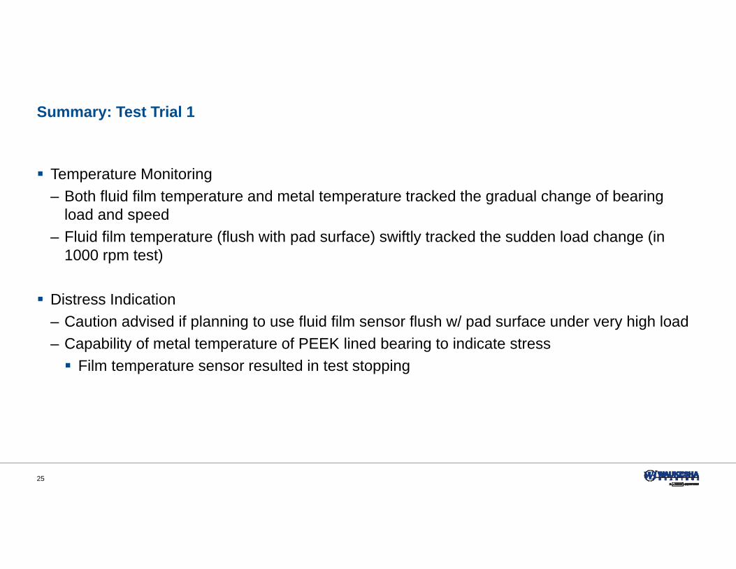
Summary: Test Trial 1
Temperature Monitoring– Both fluid film temperature and metal temperature tracked the gradual change of bearing
load and speed– Fluid film temperature (flush with pad surface) swiftly tracked the sudden load change (in
1000 rpm test)
Distress Indication– Caution advised if planning to use fluid film sensor flush w/ pad surface under very high load– Capability of metal temperature of PEEK lined bearing to indicate stress Film temperature sensor resulted in test stopping

26
Test Trial 2: Measuring Pad Fluid Film Temperature ViaHole in Pad Surface

27
PEEK Lined CQDL TPT with Hole
CQDL (Self-Equalizing ‘Directed Lubrication’) TPT with 8 PEEK lined steel pads 4 pads with TC measuring metal T 1 pad with 75/75 TC measuring fluid film T with hole
in pad surface 11,000 rpm

28
Performance Test: 11,000 rpm
0
10
20
30
40
50
60
70
80
90
0% 20% 40% 60% 80% 100% 120% 140% 160% 180% 200%
Tem
pera
ture
rise
ove
r inl
et te
mpe
ratu
re (F
)
Bearing Load Factor (%)
Fluid film (hole) T
Metal T
29
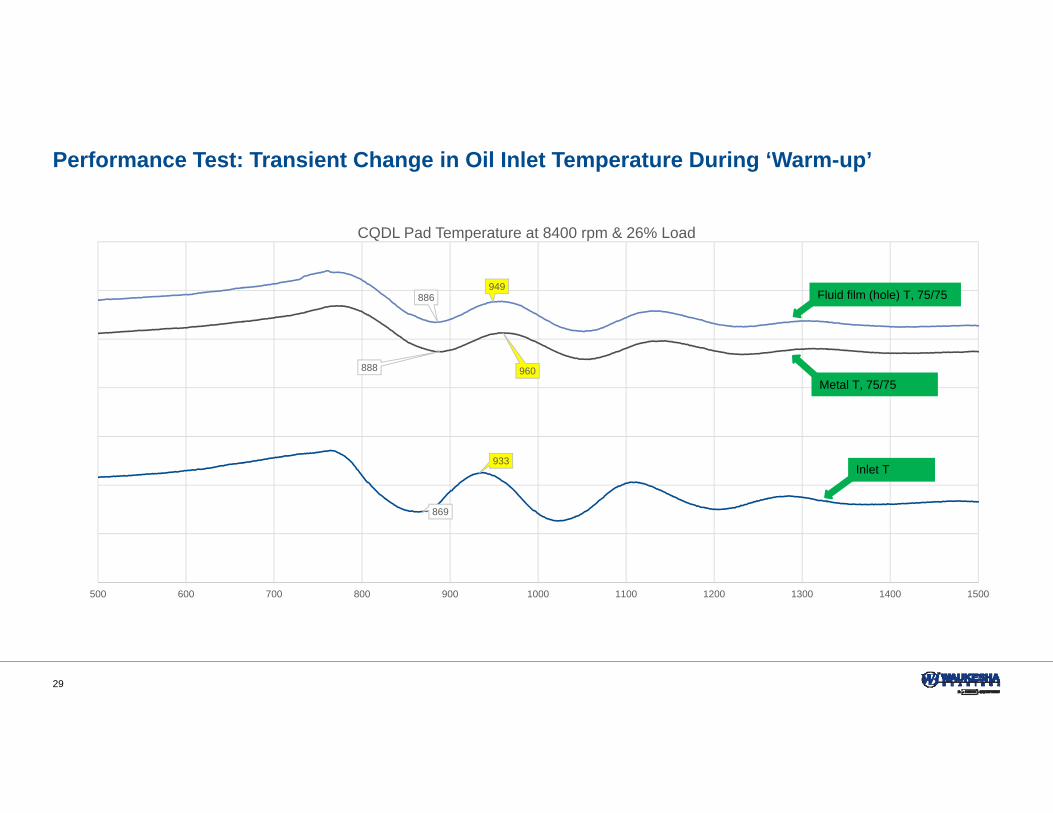
Performance Test: Transient Change in Oil Inlet Temperature During ‘Warm-up’
869
933
886949
888 960
500 600 700 800 900 1000 1100 1200 1300 1400 1500
CQDL Pad Temperature at 8400 rpm & 26% Load
Inlet T
Fluid film (hole) T, 75/75
Metal T, 75/75

30
Summary: Test Trial 2
Temperature Monitoring– Both fluid film(hole) temperature and metal temperature tracked the gradual change of
bearing load– Fluid film (hole) temperature had a shorter response time than metal temperature, as
expected Distress Indication
– Caution advised if instrument exposed to fluid film pressure– Not tested yet (prior to annual meeting)

31
Test Trial 3: Bearing Distress Indication

32
Distress Indication
Using pad fluid film temperature to indicate bearing distress has not been demonstrated– Fluid film (flush with pad surface): TC localized, misleading temperature reading; TC inaccurately indicated unacceptable
temperature change Measuring fluid film (flush surface) temperature not a reliable solution for high load
application – Fluid film (hole): Initial trial sensor unreliable No test data indicating bearing distress
Next : Distress indication using pad metal temperature– Ultimate load test of CQDL TPT with 8 PEEK lined steel pads– 4 pads with TC in metal only– Transient date from ‘ultimate’ load test at 6000 and 11,000 rpm

33
PEEK Lined CQDL TPT: Ultimate Load Test at 6000 rpm
200%
250%
300%
350%
400%
450%
30
35
40
45
50
55
60
6000 8000 10000 12000 14000 16000 18000
Bea
ring
Load
Fac
tor (
%)
Tem
pera
ture
rise
ove
r inl
et te
mpe
ratu
re(F
)
Elapsed Time (seconds)
Load
Metal T, 75/75
34
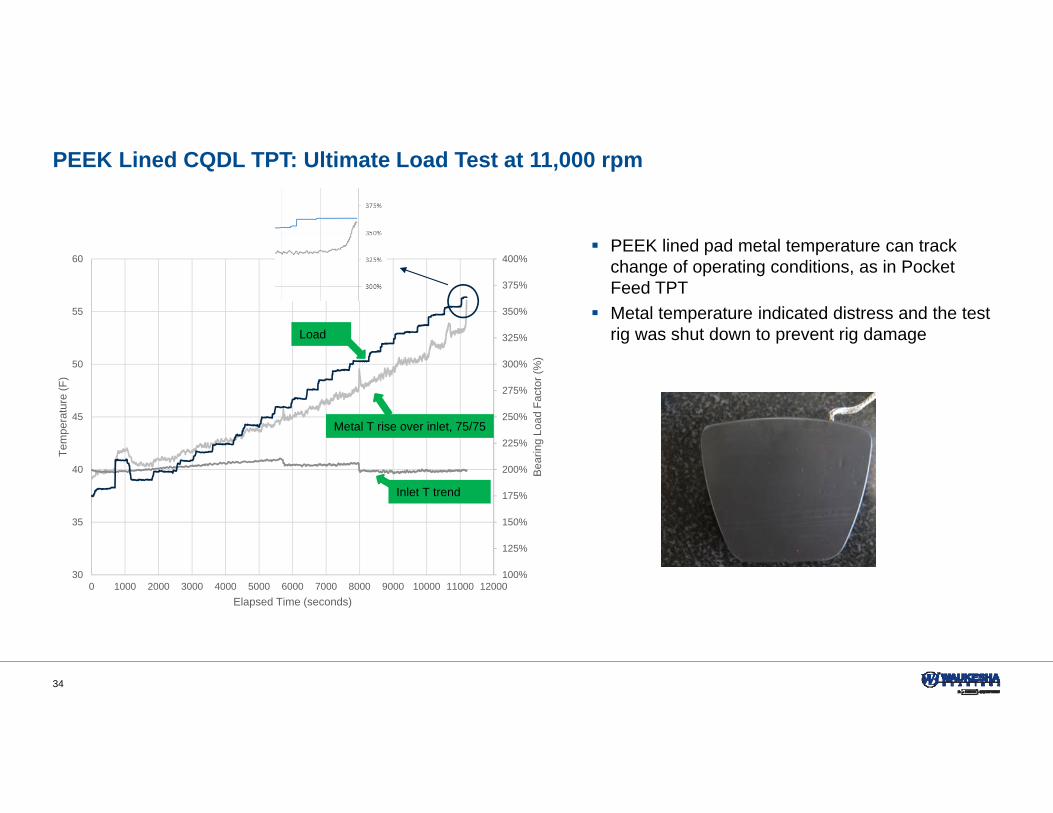
PEEK Lined CQDL TPT: Ultimate Load Test at 11,000 rpm
100%
125%
150%
175%
200%
225%
250%
275%
300%
325%
350%
375%
400%
30
35
40
45
50
55
60
0 1000 2000 3000 4000 5000 6000 7000 8000 9000 10000 11000 12000
Bea
ring
Load
Fac
tor (
%)
Tem
pera
ture
(F)
Elapsed Time (seconds)
Load
Metal T rise over inlet, 75/75
Inlet T trend
PEEK lined pad metal temperature can track change of operating conditions, as in Pocket Feed TPT
Metal temperature indicated distress and the test rig was shut down to prevent rig damage

35
Summary and Conclusions Polymer pad temperature measurement:
– Two options: material temperature and fluid film temperature– Five methods: lining material, metal backing material, fluid film (flush with pad), fluid film
(hole), and fluid film (hole) with bypass flow Both material temperature and fluid film temperature can be used to monitor PEEK pads and
track gradual change of operating condition, based on published test data Fluid film (flush with pad surface) method offer fast response, but not suggest for very high
load/high speed application. Fluid film (hole) method also has quick response. Distress indication to be validated via
additional testing Pad metal temperature can indicate bearing distress, as validated by test Recommendation
– Industrial applications: pad metal temperature is a reliable method for bearing health monitoring and an indication of bearing distress
– Lab testing: combination of metal temperature method (ultimate load) and fluid film temperature method (fast response)


