+ All Categories
Home > Documents > May 1993 - NASA · PDF fileMay 1993 N/ A A Shadowgraph Study of Two ... and documents the...

May 1993 - NASA · PDF fileMay 1993 N/ A A Shadowgraph Study of Two ... and documents the...

Date post: 12-Mar-2018
Category:
Upload: doque
View: 218 times
Download: 1 times
Share this document with a friend
56
NASA Reference Publication 1303 May 1993 N/ A A Shadowgraph Study of Two Proposed Shuttle-C Launch Vehicle Configurations A. M. Springer and D. C. Pokora (NASA-CP-13O3) A SHADOWGRAPH STUDY OF TWH PROPOS_D SHUTTLE-C LAUNCH VEHICLE CONFIGURATIONS (NASA) 45 p / L. HI/OZ .P; /) N93-271Z3 Unclas 0165067 https://ntrs.nasa.gov/search.jsp?R=19930017934 2018-05-15T04:24:58+00:00Z
Transcript

NASAReferencePublication1303

May 1993

N/ A

A Shadowgraph Study of TwoProposed Shuttle-C LaunchVehicle Configurations

A. M. Springer

and D. C. Pokora

(NASA-CP-13O3) A SHADOWGRAPH STUDY

OF TWH PROPOS_D SHUTTLE-C LAUNCH

VEHICLE CONFIGURATIONS (NASA)

45 p

/ L.

HI/OZ

.P; /)

N93-271Z3

Unclas

0165067

https://ntrs.nasa.gov/search.jsp?R=19930017934 2018-05-15T04:24:58+00:00Z

=

NASAReferencePublication1303

1993

National Aeronautics and

Space Administration

Office of Management

Scientific and Technical

Information Program

A Shadowgraph Study of TwoProposed Shuttle-C LaunchVehicle Configurations

A. M. Springer

and D. C. Pokora

George C. Marshall Space Flight Center

Marshall Space Flight Center, Alabama

ACKNOWLEDGMENTS

The authors would like to acknowledge the wind tunnel test team of Marshall Space Flight

Center. They were instrumental in running the wind tunnel test and the installation of the shadowgraph

system. A sincere thanks to H. Brewster, A. Frost, and C. Dill.

iii

TABLE OF CONTENTS

I. INTRODUCTION .............................................................................................................

II. MODEL AND FACILITY DESCRIPTION ......................................................................

A. Facility Description .....................................................................................................

B. Model Description ........................................................................................................

C. Shadowgraph System ...................................................................................................

III. SHADOWGRAPH DESCRIPTION .................................................................................

IV. CONCLUSIONS ................................................................................................................

REFERENCES ...............................................................................................................................

Page

1

1

1

12

2

3

4

LIST OF ILLUSTRATIONS

Figure

1.

2.

.

4.

5.

6.

7.

8.

9.

10.

11.

12.

13.

14.

15.

16.

17.

18.

19.

20.

21.

22.

Title

NASA MSFC's 14- by 14-in trisonic wind tunnel .........................................................

Shuttle-C reference configuration installed in the MSFC 14-inwind tunnel (TWT 715) ..................................................................................................

Shuttle-C cargo carrier configurations mated to lower stack .........................................

Sketch of shadowgraph setup .........................................................................................

Reference configuration Mach 1.46, alpha = -4, beta = 0 .............................................

Reference configuration

Reference configuration

Reference configuration

Reference configuration

Reference configuration

Reference configuration

Reference configuration

Reference configuration

Reference configuration

Reference configuration

Reference configuration

Reference configuration

Reference configuration

Reference configuration

Reference configuration

Reference configuration

Reference configuration

Mach 0.90, alpha = 0, beta = 0 ................................................

Mach 0.90, alpha = -4, beta = 0 ...............................................

Mach 0.95, alpha = 0, beta = 0 ................................................

Mach 0.95, alpha = -4, beta = 0 ...............................................

Mach 1.05, alpha = 0, beta = 0 ................................................

Mach 1.05, alpha = -4, beta = 0 ..............................................

Mach 1.10, alpha = 0, beta = 0 ................................................

Mach 1.10, alpha = -4, beta = 0 ...............................................

Mach 1.25, alpha = 0, beta = 0 .................................................

Mach 1.25, alpha = -4, beta = 0 ..............................................

Mach 1.46, alpha = 0, beta = 0 ................................................

Mach 1.46, alpha = -4, beta = 0 ...............................................

Mach 1.96, alpha = 0, beta = 0 ................................................

Mach 1.96, alpha = -4, beta = 0 ................................................

Mach 2.74, alpha = 0, beta = 0 .................................................

Mach 2.74, alpha = -4, beta = 0 ................................................

Mach 3.48, alpha = 0, beta = 0 .................................................

Page

5

6

7

8

9

12

12

13

13

14

14

15

15

16

16

17

17

18

18

19

19

20

vii

LIST OF ILLUSTRATIONS (Continued)

Figure

23.

24.

25.

26.

27.

28.

29.

30.

31.

32.

33.

34.

35.

36.

37.

38.

39.

40.

41.

42.

43.

44.

Reference configuration Mach 3.48,

Reference configuration Mach 4.95,

Reference configuration Mach 4.95,

Reference configuration Mach 0.90,

Reference configuration Mach 0.95,

Reference configuration Mach 1.05,

Reference configuration Mach 1.10,

Reference configuration Mach 1.25,

Reference configuration Mach 1.46,

Reference configuration Mach 1.96,

Reference configuration Mach 2.74,

Reference configuration Mach 3.48,

Title

alpha = -4, beta = 0 ...............................................

alpha = 0, beta = 0 ................................................

alpha = -4, beta = 0 ...............................................

alpha = 0, beta = 0, roll = 900 ...............................

alpha = 0, beta = 0, roll = 90 ° ...............................

alpha = 0, beta = 0, roll = 90 ° ...............................

alpha = 0, beta = 0, roll = 90 ° ..............................

alpha = 0, beta = 0, roll = 90 °................................

alpha = 0, beta = 0, roll = 90 ° ...............................

alpha = 0, beta = 0, roll = 90 ° ..............................

alpha = 0, beta = 0, roll = 90 ° ...............................

alpha = 0, beta = 0, roll = 90 ° ...............................

Reference configuration Mach 4.95, alpha = 0, beta = 0, roll = 90 ° ..............................

CYL-92-26-MV configuration Mach 0.90, alpha = 0, beta = 0 .....................................

CYL-92-26-MV configuration Mach 0.95, alpha = 0, beta = 0 .......................................

CYL-92-26-MV configuration Mach 0.95, alpha = -4, beta - 0 ......................................

CYL-92-26-MV configuration Mach 1.05, alpha = 0, beta = 0 .....................................

CYL-92-26-MV configuration Mach 1.05, alpha = -4, beta = 0 ....................................

CYL-92-26-MV configuration Mach 1.10, alpha = 0, beta = 0 ......................................

CYL-92-26-MV configuration Mach 1.10, alpha = -4, beta = 0 .....................................

CYL-92-26-MV configuration Mach 1.25, alpha = 0, beta = 0 ......................................

CYL-92-26-MV configuration Mach 1.25, alpha = -4, beta = 0 .....................................

Page

20

21

21

24

24

25

25

26

26

27

27

28

28

30

31

31

32

32

33

33

34

34

viii

LIST OF ILLUSTRATIONS (Continued)

Figure

45.

46.

47.

48.

49.

50.

51.

52.

53.

Title

CYL-92-26-MV configuration Mach 1.46, alpha = 0, beta = 0 .....................................

CYL-92-26-MV configuration Mach 1.46, alpha = -4, beta = 0 ....................................

CYL-92-26-MV configuration Mach 1.96, alpha = 0, beta = 0 ......................................

CYL-92-26-MV configuration Mach 2.74, alpha = 0, beta = 0 ......................................

CYL-92-26-MV configuration Mach 2.74, alpha = -4, beta = 0 ....................................

CYL-92-26-MV configuration Mach 3.48, alpha = 0, beta = 0 ......................................

CYL-92-26-MV configuration Mach 3.48, alpha = -4, beta = 0 ....................................

CYL-92-26-MV configuration Mach 4.95, alpha = 0, beta = 0 ......................................

CYL-92-26-MV configuration Mach 4.95, alpha = -4, beta = 0 .....................................

Page

35

35

36

37

37

38

38

39

39

ix

REFERENCE PUBLICATION

A SHADOWGRAPH STUDY OF TWO PROPOSED SHUTTLE-C

LAUNCH VEHICLE CONFIGURATIONS

I. INTRODUCTION

This report, the first in a series of shadowgraph studies of various launch vehicle configurations,

presents shadowgraphs of two proposed Shuttle-C configurations for the trisonic Mach range of 0.6 to

5.0. Shadowgraphs at angles-of-attack of 0 ° and -4 ° and roll angles of 90 ° are shown for the majority ofthe Mach range. These shadowgraphs present a pictorial view of the flow fields over the Shuttle-C con-

figurations. These configurations were tested in the Marshall Space Flight Center's (MSFC's) 14-in

trisonic wind tunnel over the period of October 1988 to February 1989.1

This report presents shadowgraphs for the Shuttle-C vehicle in a concise format, offers a means

of easy transfer of the data to interested parties, and documents the results for future study.

H. MODEL AND FACILITY DESCRIPTION

A. Facility Description

The MSFC 14- by 14-in trisonic wind tunnel is an intermittent blowdown tunnel which operates

by high pressure air flowing from storage to either vacuum or atmosphere conditions. The transonic test

section, with variable porous walls, provides a Mach number range from 0.2 to 2.0. A solid-wail super-

sonic test section provides the entire range from 2.74 to 5.0 with one set of automatically actuated con-

tour blocks. Downstream of the test section is a hydraulically controlled pitch sector that provides the

capability of testing up to 20 angles-of-attack from -10 ° to +10 ° during each run. Sting offsets are avail-able for obtaining various maximum angles-of-attack up to 90 °. This is further detailed in reference 2.

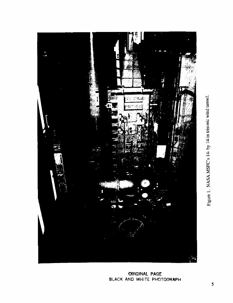
The MSFC 14- by 14-in trisonic wind tunnel facility is shown in figure 1.

B. Model Description

The 0.004 scale Shuttle-C models consisted of two cargo carrier (CC) configurations mated to

the space transportation system (STS) lower stack and an external tank (ET) with two solid rocket

boosters (SRB's). The CC models were representations of the Shuttle-C sidemount concepts studied.

These models consisted of a cylindrical-shaped forward body with an STS boattail. The reference con-

figuration was a cylindrical body of 82-ft length and 18.3-ft (full scale) diameter. The nose was a 26.5 °

half-angle nose cone that was blunted with a nose radius of 3.542 ft (full scale). The orbital maneuvering

system (OMS) pods were mounted in the same relative position as they are on the STS orbiter. Figure 2

shows the reference configuration mounted in the trisonic wind tunnel. Another configuration tested wasidentical to the reference configuration but the forward cylinder was extended to 92 ft (full scale). Figure

3 is a comparison sketch of the two configurations. Shadowgraphs were taken for these two configura-tions.

C. Shadowgraph System

The 14-in wind tunnel's shadowgraph system consists of a spark source, multiple film holders,

and a mounting bracket for the holders. The spark source is mounted on one side with the mountingbracket/film holder on the other side of the test section. Glass wail inserts are installed in the transonic

test section, while the supersonic test section has conventional windows. The spark source is fired,

exposing the film, thus producing a shadowgraph. Figure 4 shows a sketch of the shadowgraph setup.

Without flow, the spark source shines through the test section containing stagnant air and illumi-nates the film with uniform intensity. When the tunnel is started and flow passes through the test section,

the light beam will be refracted wherever there is a density gradient. A constant gradient, an empty test

section, will result in every light ray being refracted evenly, producing no change on the film. Only if

there is a variation in the density gradient will the light from the spark source converge or diverge. A

picture of the instantaneous density gradients is shown on the film when the spark source is fired. The

shadowgraph easily allows shock waves to be seen. A density gradient is positive upstream of the shock

and negative downstream. The shadowgraph film shows the shock wave as a dark line followed by awhite line.

The shadowgraph system used for the 14-in wind tunnel is explained in detail in reference 3.

Reference 3 also explains the theory behind the system and the supporting tests done to initially verify

the system. This reference also explains the effects of the glass wails on the shadowgraph. This appearson the shadowgraph to look something like cross hatching in the subsonic and sonic Mach range.

Currently only the single-film method, not the multiple-exposure roll which is also shown in reference 3,

is used. Kodak Tri-X 8- by 20-in, black and white, pan professional film is used for the shadowgraphs.

HI. SHADOWGRAPH DESCRIPTION

The shadowgraph is a flow visualization technique that shows the second spatial derivative of the

density field or the gradient of the density gradient. The shadowgraph is used to show boundary layers,

flow separation, and shock wave formations. All flow visualization techniques are dependent on varia-tion in the flow fields density. An interferometer measures the density level with regards to a reference.

The fringe shifts are counted to obtain the density variations. A Schlieren system shows the gradient in

density or the f'u'st x derivative. The shadowgraph system is easy to use and the relative shock strengths

are easily seen, but the actual density levels cannot be obtained.

Boundary layers and separated regions are easily seen in shadowgraphs if the flow field densityis not tot) low. The density changes across shocks, and expansions waves are governed by the ratioswhich are functions of Mach number and flow direction. The density gradients of the flow are dependent

on the ratios of upstream and downstream flow fields. This dependence results in low-density flow fields

not being as clear as high-density flow in the shadowgraphs. The shadowgraph system and its relation to

other optical flow methods are discussed in reference 4. Further details concerning shadowgraphs and

their application to launch vehicle aerodynamic study are found in reference 5.

These visual representations of the flow are used in the venting analysis and aerodynamic analy-

sis of the vehicle.

2

IV. CONCLUSIONS

Shadowgraphs are presented for the trisonic range of Mach numbers for two proposed Shuttle-C

configurations. The shadowgraphs show the effects of Mach number, angle of attack, angle of sideslip,and cargo carrier configuration. The shadowgraphs presented are of great use in the analysis of the aero-dynamic characteristics for the presented configurations.

The Shuttle-C configuration is a multibody side-mounted configuration, like the shuttle. This

type configuration results in significant interactions between the components. Part of the interaction

between components is due to the interaction of the bow shock waves off each of the components. This

can be seen in figure 32 and 18, a top and side view of the reference configuration.

The effects of the differences in configuration, i.e., payload bay length, can be seen in these

shadowgraphs. The flow fields are generally the same for both configurations. The Shuttle-C cargo

carrier nose or bow shock wave is moved forward on the 92-ft length payload model (fig. 45) as com-

pared to the reference configuration (fig. 16). This moves the shock impingement point on the ET andchanges the interference pattems between the cargo carrier and the lower stack.

In general, shock waves seen at lower Mach numbers appear as vertical lines forward of the

vehicle. As Mach number increases, a shock wave traverses the vehicle and changes from the appear-

ance of a vertical line, a normal shock, to that of an oblique line, an oblique shock.

At the higher Mach numbers, the shadowgraphs appear to be clearer and shock waves more pro-nounced. This is due to the larger density variation fore and aft of the shock.

The flow phenomena around the reference configuration, as seen in a typical shadowgraph, isshown in figure 5. This figure is the same shadowgraph as figure 17, but with the major points of theflow field highlighted.

3

REFERENCES

°

*

.

*

*

Pokora, D.C.: "Posttest report for the Shuttle-C Test in the MSFC 14-Inch Trisonic Wind Tunnel

(TWT 715)." ED35-17-89, February 28, 1989.

Simon, E.H.: "The George C. Marshall Space Flight Center's 14x14 Inch Trisonic Wind TunnelTechnical Handbook." NASA TMX-64624, November 5, 1971.

Clark, J., Heaman, J.P., and Stewart, D.L.: "14-Inch Wind Tunnel Spark Shadowgraph System."

NASA TM X-53196, January 22, 1965.

Shapiro, A.H.: "The Dynamics and Thermodynamics of Compressible Fluid Flow Volume I." John

Wiley and Sons, Inc., 1953, Chapter 3.7. Optical Methods of Investigation, p. 59-68.

Andrews, C.D., and Carlson, D.R.: "Shadowgraph Study of the Upper Stage Flow Fields of Some

Satum V Study Configurations in the Transonic Mach Number Range." NASA TN D-2755, April1965.

4

ORIGINAL PAGE

BLACK AND WHITE PHOTOGRAPH5

6

eJ

°_

[JL_

:Eej

.c=

°v,.q

O

L=

O

L)

_J

;=

(q

°_

[.L

OR1GtNAL PAGE

_JLACK AND WHITE PFIOTO(_pH

cO

¢/)

f-

r-

IT)c0

r-

E

"0

\/

C_Q)aL_

'_1 m r"_"i !

gin'

I

\ /\ /

W

0

0

0

I-i

0

, ....q

0

1FLOW

FILM MODEL

SPARK SOURCE

GLASS WALL GLASS WALL

Figure 4. Sketch of shadowgraph setup.

8

0

I-iii

9

SECTION I

Reference Configuration

Alpha = 0, Beta = 0

Alpha = -4, Beta = 0

Roll Angle = 0

_,:Ic'./

11

Figure 6.

T

Reference configuration Mach 0.90, alpha = 0, beta = 0.

Figure 7. Reference configuration Mach 0.90, alpha = -4, beta = 0.

12

Figure 8. ReferenceconfigurationMach0.95,alpha= 0, beta= 0.

Figure9.

1

ReferenceconfigurationMach0.95,alpha= --4,beta= 0.

13

Figure 10. ReferenceconfigurationMach1.05,alpha= 0, beta= 0.

Figure 11. ReferenceconfigurationMach1.05,alpha= -4, beta= 0.

\\

14

Figure 12. Reference configuration Mach 1.10, alpha = 0, beta = 0.

Figure 13. Reference configuration Mach 1.10, alpha = -4, beta = 0.

15

Y,1

Figure 14. Reference configuration Mach 1.25, alpha = 0, beta = 0

-\

!

|

&

Figure 15. Reference configuration Mach 1.25, alpha = -4, beta = 0.

16

Figure 16. ReferenceconfigurationMach1.46,alpha= 0, beta= 0.

Figure 17. ReferenceconfigurationMach 1.46,alpha= -4, beta= 0.

\

17

Figure 18. ReferenceconfigurationMach 1.96,alpha= 0, beta= 0.

Figure 19. ReferenceconfigurationMach 1.96,alpha= --4,beta= 0.

18

J

Figure 20. Reference configuration Mach 2.74, alpha = 0, beta = 0.

Figure 21. Reference configuration Mach 2.74, alpha = -4, beta = 0.

19

Figure22. ReferenceconfigurationMach3.48,alpha= 0, beta= 0.

Figure23. ReferenceconfigurationMach3.48,alpha= -4, beta= 0.

20

Figure24. ReferenceconfigurationMach4.95,alpha= 0, beta= 0.

h

iS

j_

j

Figure 25. Reference configuration Mach 4.95, alpha = -4, beta = 0.

21

SECTION II

Reference ConfigurationAlpha = 0, Beta = 0

Roll Angle = 90 °

23

Figure 26. Reference configuration Mach 0.90, alpha = 0, beta = 0, roll = 90 °.

Figure 27. Reference configuration Mach 0.95, alpha = 0, beta = 0, roll = 90 °.

24

Figure28. ReferenceconfigurationMach1.05,alpha= 0, beta= 0, roll = 90°.

Figure29. ReferenceconfigurationMach 1.10,alpha= 0, beta= 0, roll = 90°.

25

Figure30. ReferenceconfigurationMach 1.25,alpha= 0, beta= 0,roll = 90°.

Figure31. ReferenceconfigurationMach 1.46,alpha= 0, beta= 0, roll = 90°.

26

Figure32. ReferenceconfigurationMach1.96,alpha= O,beta= O,roll = 90°.

Figure33. ReferenceconfigurationMach2.74,alpha= 0, beta= 0,roll = 90°.

27

Figure34. ReferenceconfigurationMach3.48,alpha= 0, beta= 0, roll = 90".

m

Figure 35. Reference configuration Mach 4.95, alpha = 0, beta = 0, roll = 90 °.

28

SECTION HI

CYL-92-26-MV Configuration

Alpha = 0, Beta = 0Alpha = -4, Beta = 0

Roll = 0

29

Figure36. CYL-92-26-MV configurationMach0.90,alpha= 0, beta= 0

30

Figure37. CYL-92-26-MV configurationMach0.95,alpha= 0, beta= 0

Figure38. CYL-92-26-MV configurationMach0.95,alpha= -4, beta= 0

31

Figure 39. CYL-92-26-MV configuration Mach 1.05, alpha = 0, beta = 0

Figure 40. CYL-92-26-MV configuration Mach 1.05, alpha = -4, beta = 0

32

Figure41. CYL-92-26-MV configurationMach1.10,alpha= 0, beta= 0

Figure42. CYL-92-26-MV configurationMach1.10,alpha= -4, beta= 0

33

Figure 43. CYL-92-26-MV configuration Mach 1.25, alpha = 0, beta = 0

/

/

Figure 44. CYL-92-26-MV configuration Mach 1.25, alpha = -4, beta = 0

34

Figure45. CYL-92-26-MV configurationMach 1.46,alpha= 0, beta= 0

\

Figure 46. CYL-92-26-MV configuration Mach 1.46, alpha = -4, beta = 0

35

Figure47. CYL-92-26-MV configurationMach1.96,alpha= 0, beta= 0

36

__ i _i̧ _ _

Figure 48. CYL-92-26-MV configuration Mach 2.74, alpha = 0, beta = 0

Figure 49. CYL-92-26-MV configuration Mach 2.74, alpha = -4, beta = 0

37

Figure50. CYL-92-26-MV configurationMach3.48,alpha= 0, beta= 0

Figure51. CYL-92-26-MV configurationMach3.48,alpha= -4, beta= 0

38

Figure52. CYL-92-26-MV configurationMach4.95,alpha= 0, beta= 0

Figure53. CYL-92-26-MV configurationMach4.95,alpha= -4, beta= 0

39

Form Approved

REPORT DOCUMENTATION PAGE o_._E_o c:o. c188

gathe,,t_g and maintaining the _3a_ane_ed, an0 completmq ana tev_ewmc _e :oIle-_lOn ot ,_orm_tlon S_ _,_mme_T_reaa-3 n= T_ s D_rae_ _st_m t_ Or _n, brier _cl O_l"_ScolleCt<_nof information, qnclua_ng _uggest_ons |or reduom9 _h_ D_Jroe_ _o W_h_ngton _eaoauar_ers _er_,ce_, DIre_or_e _o_ _t_rma_rC_ Ome_tlor_ and _?ocr% _2 _5 Je÷ter%onOavl_ H_g_way. Suite 204 Af_ r_g_:on,V_ 22202_02 dn_ _o t_e O_'f_ceof Ma_ager_e_ at_o 8uCfge_,Pa_rw_c_ Reductlo_ Pro ect (0704_188) Wast_fr_g_Or_r_ 2_50_

1. AGENCY USE ONLY (Leave blank) 2. REPORT DATE 3. REPORT TYPE AND DATES COVERED

Vmy 1993 Reference Publica_ion4. TITLE AND SUBTITLE 5. FUNDING NUMBERS

A Shadowgraph Study of Two Proposed Shuttlc-C Launch Vehicle

Configurations6. AUTHOR(S)

A.M. Springer and D.C. Pokora

7. PERFORMING ORGANIZATI(_I NAME(S) AND ADDRESS(ES)

George C. Marshall Space Flight Center

Marshall Space Flight Center, Alabama 35812

_. sPoNsORING/MONITORING AGENCY NAME(S) AND AOORESS(ES)

National Aeronautics and Space Administration

Washington, DC 20546

B. PERFORMING ORGANIZATIONREPORT NUMBER

M-718

10. SPONSORING/MONITORING

AGENCY REPORT NUMBER

NASA RP-1303

It..SUPPLEMENTARYNOTESPrepared by Svructures and Dynamics Laboratory, Science and Engineering Directorate.

12a. DISTRIBUTION 1AVAILABILITY STATEMENT

Unclassified -- Unlimited

Subject Category: 02

12b, DISTRIBUTION CODE

13. ABSTRACT (Maximum 200 words)

Thisreportpresentsashadowgraphstudyconcerningtwo oftheproposedShuttle-Claunch

vehicleconfigurations.These shadowgraphswere obtainedfrom a wind tunneltestperformedin

Marshall Space Flight Center's 14-.in trisonic wind tunnel at various angles-of-attack and roll angles

over the Mach range of 0.6 to 4.96. Variations in payload bay length were also evaluated. Major flow

field phenomena can easily be seen in the shadowgraphs. $hadowgraphs are a valuable resource. They

are used in the analysis of the external flow conditions the launch vehicle encounters through the ascent

stage of flight. Subsequent reports will contain shadowgraph studies for other launch vehicle configura-tions also tested in the Marshall Space Flight Center's 14-in trisonic wind runnel.

|14. SUBJECT TERMS

shadowgraph, Shuttle-C, wind tunnel testing, flow visualization,launch vehicle

17. SECURITY CLASSIFICATION lB. SECURITY CLASSIFICATION

REPORT OF THIS PAGE

Unclassified Unclassified

NSN 7540-01-2_0-5S00

15, NUMBER OF PAGES

16. PRII_E CODE

A0319. SECURITY CLASSIFICATION 20. LIMITATION OF ABSTRACT

OF ABSTRACT

Unclassified Unlimited

Standard Form 298 (Rev 2-B9)Prc_$crlDe_by ANSI _td Z]19-18298-102

_U.9. GOVERNMENT PRINTING OFFICE: 1993 * 728-064/66039

National Aeronautics and

Space AdministrationCode JTT

Washington, D.C.20546-0001

Official Business

Penalty for Private Use, $300

BULK RATE

POSTAGE & FEES PAIDNASA

Permit No. G-27

hl/L.RA POSTMASTER: If Undeliverable (Section 158Postal Manual) Do Not Return


Recommended