94
Training Manual Mazda3 Facelift FL-005
Training Manual
Mazda3 Facelift FL-005
No part of this hardcopy may be reproduced in any form without prior permission of Mazda Motor Europe GmbH. The illustrations, technical information, data and descriptive text in this issue, to the best of our knowledge, were correct at the time of going to print. No liability can be accepted for any inaccuracies or omissions in this publication, although every possible care has been taken to make it as complete and accurate as possible. © 2006 Mazda Motor Europe GmbH Training Services
Table of Contents
General Information ..........................................................................00-1 Technical Data ............................................................................................................00-1 Vehicle Identification Number ...................................................................................00-2 Scheduled Maintenance.............................................................................................00-3
Engine ................................................................................................01-1 1.3 MZR Engine...........................................................................................................01-1
Features ................................................................................................................01-1 Overview................................................................................................................01-1 Mechanical ............................................................................................................01-2
Camshaft ........................................................................................................01-2 2.0 MZR Engine...........................................................................................................01-3
Features ................................................................................................................01-3 Engine Performance Curve ...................................................................................01-4 Overview................................................................................................................01-5
1.6 MZ-CD Engine.......................................................................................................01-6 Features ................................................................................................................01-6 Overview................................................................................................................01-6 Fuel System...........................................................................................................01-7
Features .........................................................................................................01-7 Parts Location.................................................................................................01-7 High-pressure Pump.......................................................................................01-8
Control System....................................................................................................01-10 Features .......................................................................................................01-10 Parts Location...............................................................................................01-10 Block Diagram ..............................................................................................01-12 Glow Plug Relay ...........................................................................................01-14 Cruise Control System..................................................................................01-15
Suspension ........................................................................................02-1 Features ................................................................................................................02-1
Front Suspension.......................................................................................................02-2 Rear Suspension ........................................................................................................02-3
Driveline/Axle.....................................................................................03-1 Features ................................................................................................................03-1
Front Axle....................................................................................................................03-1 Drive Shaft...................................................................................................................03-2
Service Training Mazda3 F/L
Table of Contents
Transmission/Transaxle ...................................................................05-1 G66M-R Manual Transaxle.........................................................................................05-1
Features ................................................................................................................05-1 Specifications ........................................................................................................05-1 Overview................................................................................................................05-2 Shift Mechanism....................................................................................................05-3
Reverse Lockout Mechanism .........................................................................05-4 FN4A-EL Automatic Transaxle ..................................................................................05-5
Features ................................................................................................................05-5 Overview................................................................................................................05-5 Shift Mechanism....................................................................................................05-7
Shift-lock System/Key Interlock System .........................................................05-8
Restraints...........................................................................................08-1 Airbag System ............................................................................................................08-1
Features ................................................................................................................08-1 Parts Location........................................................................................................08-2 Wiring Diagram......................................................................................................08-3 Ball-type Seat Belt Pretensioners..........................................................................08-4
Body & Accessories..........................................................................09-1 Body Panels ................................................................................................................09-1
Features ................................................................................................................09-1 Front End...............................................................................................................09-1
Glass/Windows/Mirrors..............................................................................................09-2 Features ................................................................................................................09-2 Exterior Opening/Closing Function........................................................................09-2
Parts Location.................................................................................................09-3 Security and Locks.....................................................................................................09-4
Features ................................................................................................................09-4 Advanced Keyless Entry and Start System ...........................................................09-4
Parts Location.................................................................................................09-5 Wiring Diagram...............................................................................................09-6 Trunk Lid Request Switch...............................................................................09-8 Keyless Control Module..................................................................................09-9 Operation......................................................................................................09-10 Warning and Guidance Function ..................................................................09-10 Customization...............................................................................................09-11 Service and Repair .......................................................................................09-12 Immobilizer System ......................................................................................09-14 On-board Diagnostic System........................................................................09-18
Service Training Mazda3 F/L
Table of Contents
Exterior Trim .............................................................................................................09-20 Features ..............................................................................................................09-20 Parts Location......................................................................................................09-21
Interior Trim ..............................................................................................................09-22 Features ..............................................................................................................09-22 Parts Location......................................................................................................09-22
Lighting Systems......................................................................................................09-23 Features ..............................................................................................................09-23 Headlight Auto-leveling System...........................................................................09-23
Parts Location...............................................................................................09-23 Wiring Diagram.............................................................................................09-24 Initialization procedure for auto-leveling control module ..............................09-25
Entertainment ...........................................................................................................09-26 Features ..............................................................................................................09-26 Audio System ......................................................................................................09-26
Music Hard Disc Drive Specifications...........................................................09-26 Parts Location...............................................................................................09-27 System Overview..........................................................................................09-28 Audio Unit .....................................................................................................09-29
Instrumentation/Driver Info .....................................................................................09-30 Features ..............................................................................................................09-30 Instrument Cluster ...............................................................................................09-30
Overview.......................................................................................................09-30 Odometer Write Procedure...........................................................................09-32 Freeze Frame Data ......................................................................................09-33
Seat Belt Reminder System ................................................................................09-34 Buckle Switches ...........................................................................................09-34 Occupancy Sensor .......................................................................................09-34 Front Seat Belt Reminder Operation ............................................................09-36 Rear Seat Belt Reminder Operation.............................................................09-37
Control System.........................................................................................................09-38 Features ..............................................................................................................09-38 Controller Area Network ......................................................................................09-38
High-speed CAN Signal Chart......................................................................09-40 Mid-speed CAN Signal Chart .......................................................................09-42
Service Training Mazda3 F/L
Table of Contents
Service Training Mazda3 F/L
General Information
Technical Data
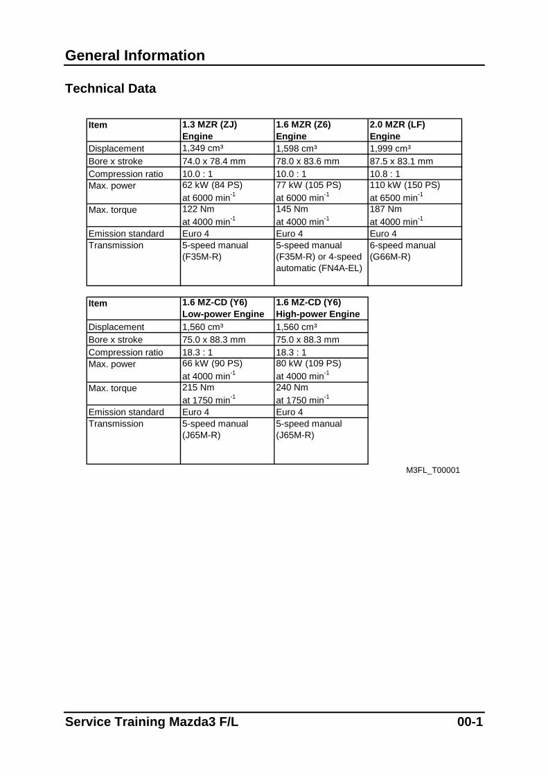
Item 1.3 MZR (ZJ)
Engine1.6 MZR (Z6)Engine
2.0 MZR (LF)Engine
Displacement 1,349 cm³ 1,598 cm³ 1,999 cm³Bore x stroke 74.0 x 78.4 mm 78.0 x 83.6 mm 87.5 x 83.1 mmCompression ratio 10.0 : 1 10.0 : 1 10.8 : 1Max. power 62 kW (84 PS)
at 6000 min-177 kW (105 PS)at 6000 min-1
110 kW (150 PS) at 6500 min-1
Max. torque 122 Nmat 4000 min-1
145 Nmat 4000 min-1
187 Nm at 4000 min-1
Emission standard Euro 4 Euro 4 Euro 4Transmission 5-speed manual
(F35M-R)5-speed manual (F35M-R) or 4-speedautomatic (FN4A-EL)
6-speed manual(G66M-R)
Item 1.6 MZ-CD (Y6)Low-power Engine
1.6 MZ-CD (Y6)High-power Engine
Displacement 1,560 cm³ 1,560 cm³Bore x stroke 75.0 x 88.3 mm 75.0 x 88.3 mmCompression ratio 18.3 : 1 18.3 : 1Max. power 66 kW (90 PS)
at 4000 min-180 kW (109 PS)at 4000 min-1
Max. torque 215 Nmat 1750 min-1
240 Nmat 1750 min-1
Emission standard Euro 4 Euro 4Transmission 5-speed manual
(J65M-R)5-speed manual(J65M-R)
M3FL_T00001
Service Training Mazda3 F/L 00-1
General Information
Vehicle Identification Number
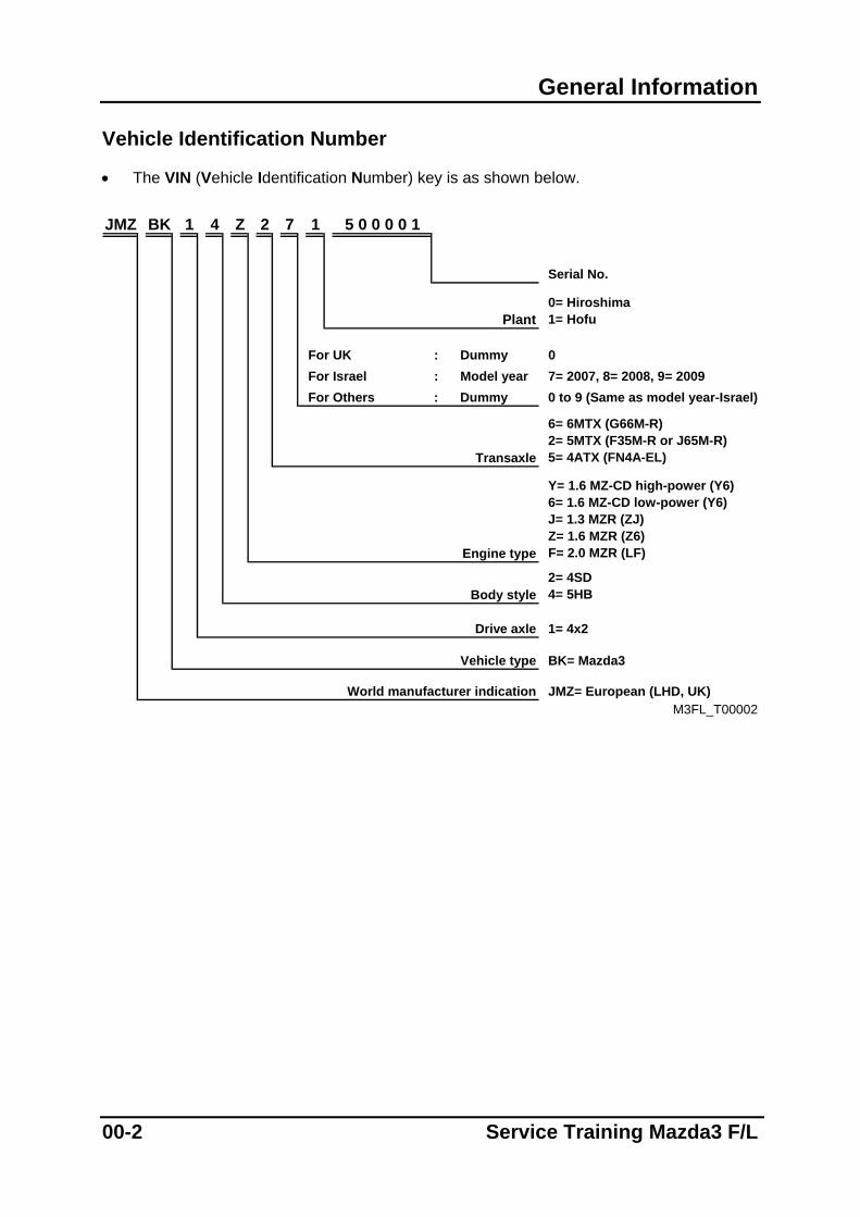
• The VIN (Vehicle Identification Number) key is as shown below. JMZ BK 1 4 Z 2 7 1 5 0 0 0 0 1
Serial No.
Plant0= Hiroshima1= Hofu
For UK : Dummy 0For Israel : Model year 7= 2007, 8= 2008, 9= 2009For Others : Dummy 0 to 9 (Same as model year-Israel)
Transaxle
6= 6MTX (G66M-R)2= 5MTX (F35M-R or J65M-R)5= 4ATX (FN4A-EL)
Engine type
Y= 1.6 MZ-CD high-power (Y6)6= 1.6 MZ-CD low-power (Y6)J= 1.3 MZR (ZJ)Z= 1.6 MZR (Z6)F= 2.0 MZR (LF)
Body style2= 4SD4= 5HB
Drive axle 1= 4x2
Vehicle type BK= Mazda3
World manufacturer indication JMZ= European (LHD, UK) M3FL_T00002
00-2 Service Training Mazda3 F/L
General Information
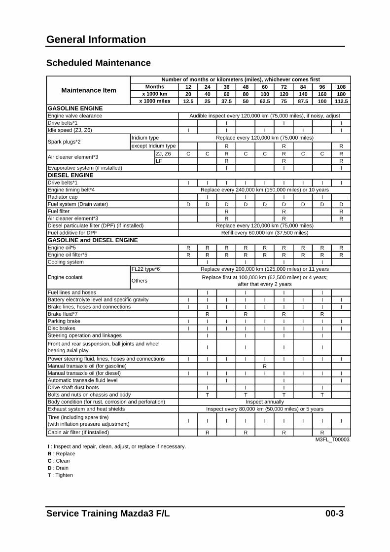
Scheduled Maintenance
12 24 36 48 60 72 84 96 10820 40 60 80 100 120 140 160 180
12.5 25 37.5 50 62.5 75 87.5 100 112.5
I I II I I I I
R R RZJ, Z6 C C R C C R C C RLF R R R
I I I
I I I I I I I I I
I I I ID D D D D D D D D
R R RR R R
R R R R R R R R RR R R R R R R R R
I I I I
I I I II I I I I I I I II I I I I I I I I
R R R RI I I I I I I I II I I I I I I I I
I I I I
I I I I
I I I I I I I I IR
I I I I I I I I II I I
I I I IT T T T
I I I I I I I I I
R R R R
I : Inspect and repair, clean, adjust, or replace if necessary.R : ReplaceC : CleanD : DrainT : Tighten
M3FL_T00003
Engine coolantFL22 type*6 Replace every 200,000 km (125,000 miles) or 11 years
Others Replace first at 100,000 km (62,500 miles) or 4 years;after that every 2 years
Inspect annuallyInspect every 80,000 km (50,000 miles) or 5 years
Fuel lines and hosesBattery electrolyte level and specific gravity
Replace every 240,000 km (150,000 miles) or 10 years
Air cleaner element*3
Engine valve clearanceDrive belts*1
Replace every 120,000 km (75,000 miles)
Engine timing belt*4
DIESEL ENGINE
Idle speed (ZJ, Z6)Iridium typeexcept Iridium type
Monthsx 1000 km
x 1000 miles
Drive belts*1
Maintenance Item
GASOLINE ENGINE
Spark plugs*2
Evaporative system (if installed)
Audible inspect every 120,000 km (75,000 miles), if noisy, adjust
Number of months or kilometers (miles), whichever comes first
Radiator capFuel system (Drain water)Fuel filterAir cleaner element*3
Replace every 120,000 km (75,000 miles)Refill every 60,000 km (37,500 miles)
GASOLINE and DIESEL ENGINEFuel additive for DPF
Engine oil*5
Diesel particulate filter (DPF) (if installed)
Cooling systemEngine oil filter*5
Brake lines, hoses and connections
Bolts and nuts on chassis and body
Brake fluid*7Parking brakeDisc brakesSteering operation and linkagesFront and rear suspension, ball joints and wheel bearing axial playPower steering fluid, lines, hoses and connectionsManual transaxle oil (for gasoline)Manual transaxle oil (for diesel)Automatic transaxle fluid level
Cabin air filter (If installed)
Drive shaft dust boots
Body condition (for rust, corrosion and perforation)Exhaust system and heat shieldsTires (including spare tire)(with inflation pressure adjustment)
Service Training Mazda3 F/L 00-3
General Information
• Refer below for a description of items marked * in the maintenance chart:
– *1: Also inspect and adjust the power steering and air conditioner drive belts, if installed.
– *2: Verify the spark plug type from the installed spark plugs. Refer to specifications.
– *3: If the vehicle is operated in very dusty or sandy areas, clean and if necessary replace the air cleaner element more often than the recommended intervals.
– *4: Replacement of the timing belt is required every 240,000 km {150,000 miles} or 10 years. Failure to replace the timing belt may result in a major damage to the engine.
– *5: If the vehicle is operated under hard conditions (dusty road, extended periods of idling or low speed operation, cold temperature or driving short distances), change the engine oil and oil filter every 10,000 km {6,250 miles} or less.
– *6: When replacing the coolant on vehicles with the inscription “FL22” on the radiator cap itself or the surrounding area, use only coolant of this type.
– *7: If the brakes are used extensively (for example, continuous hard driving or mountain driving) or if the vehicle is operated in extremely humid climates, change the brake fluid annually.
00-4 Service Training Mazda3 F/L
Engine 1.3 MZR Engine
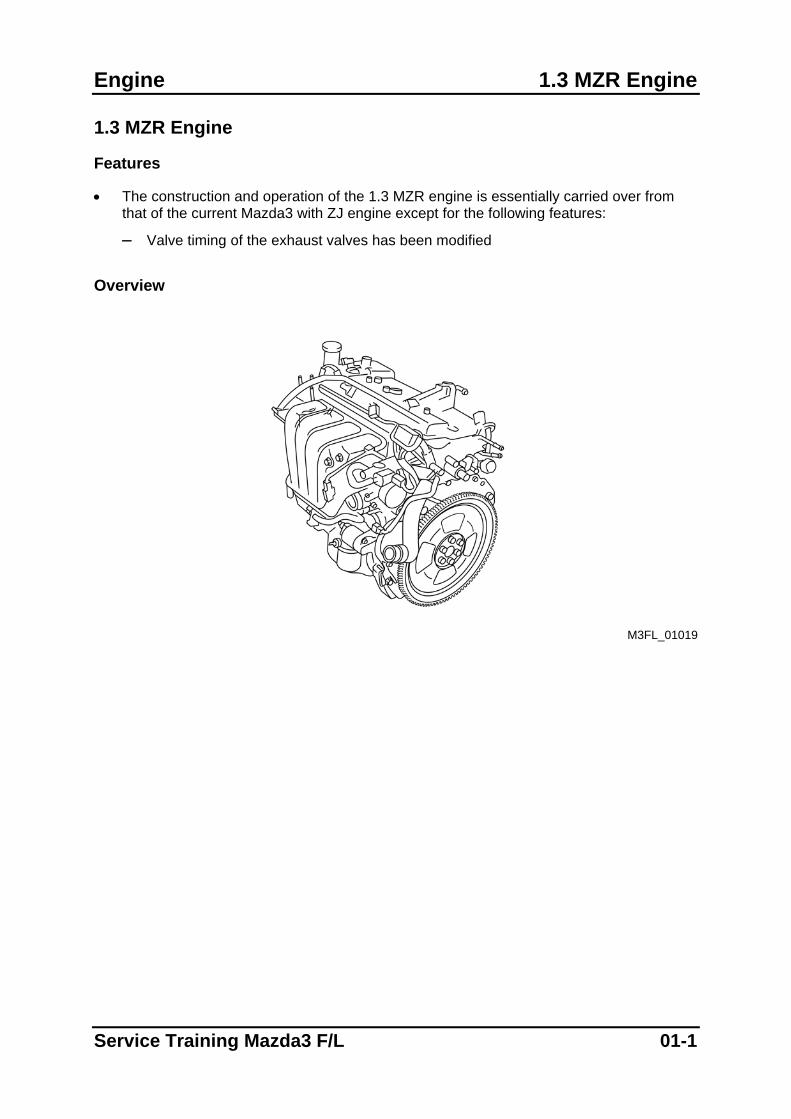
1.3 MZR Engine
Features
• The construction and operation of the 1.3 MZR engine is essentially carried over from that of the current Mazda3 with ZJ engine except for the following features:
– Valve timing of the exhaust valves has been modified Overview
M3FL_01019
Service Training Mazda3 F/L 01-1
Mechanical 1.3 MZR Engine
Mechanical
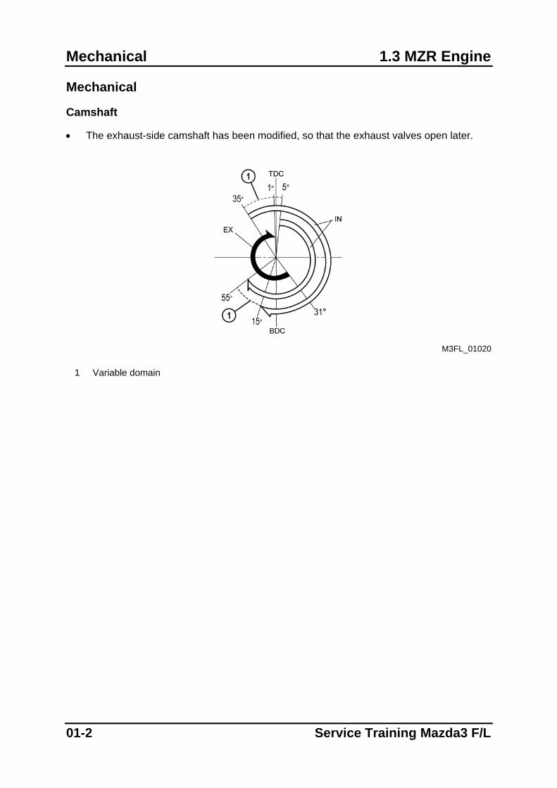
Camshaft
• The exhaust-side camshaft has been modified, so that the exhaust valves open later.
M3FL_01020
1 Variable domain
01-2 Service Training Mazda3 F/L
Engine 2.0 MZR Engine
2.0 MZR Engine
Features
• The construction and operation of the 2.0 MZR engine is essentially carried over from that of the current Mazda3 with LF engine except for the following features:
– Electronic throttle valve with drive-by-wire relay and accelerator pedal position sensor (similar to that of the Mazda6 F/L)
– Direct ignition coils with integrated power transistor (similar to those of the Mazda6 F/L)
– Linear-type (Broadband) upstream oxygen sensor (similar to that of the Mazda6 F/L)
– Generator with two stator coils (similar to that of the Mazda6 F/L)
– Magneto resistive-type crankshaft and camshaft position sensor (similar to that of the Mazda6 F/L)
– Variable valve timing system with oil control valve and camshaft actuator (similar to that of the Mazda6 F/L)
– Cruise control system integrated in the PCM, with cruise control switches and brake pedal position switch (similar to that of the Mazda6 F/L)
NOTE: Further information can be found in the Training Manual “Basic Petrol Engine
Management” (CT-L2004)
Service Training Mazda3 F/L 01-3
2.0 MZR Engine Engine
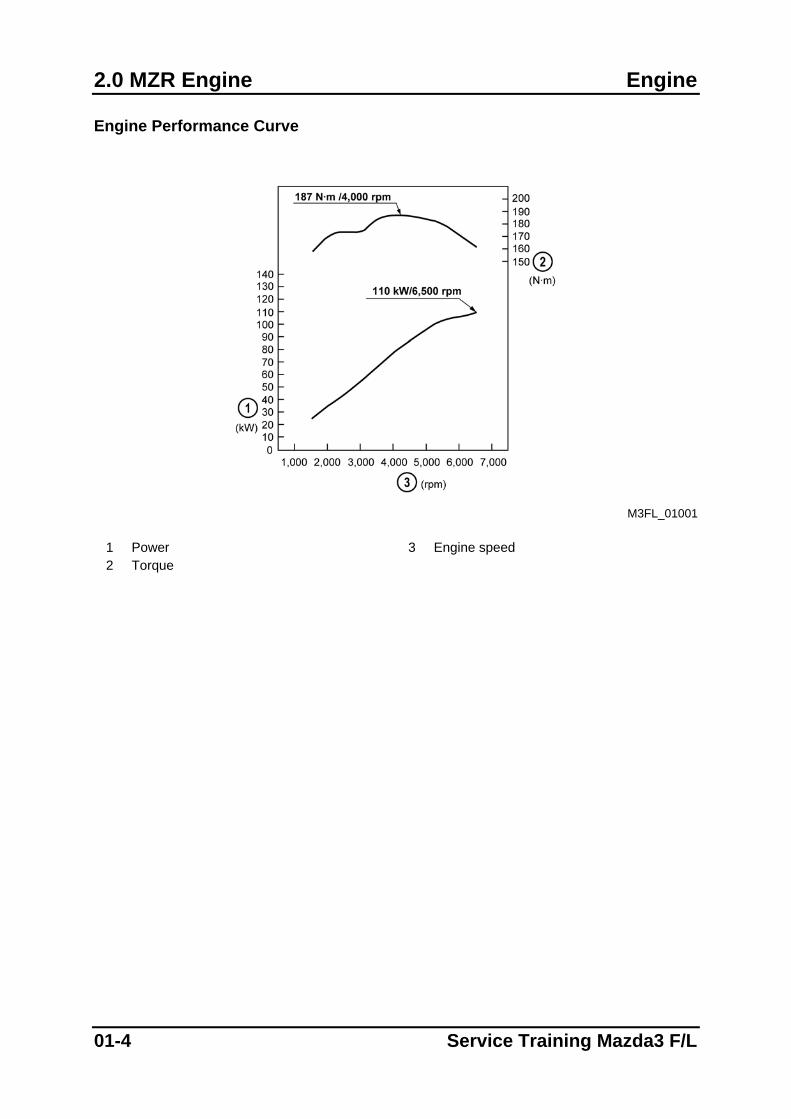
Engine Performance Curve
M3FL_01001
1 Power 3 Engine speed 2 Torque
01-4 Service Training Mazda3 F/L
Engine 2.0 MZR Engine
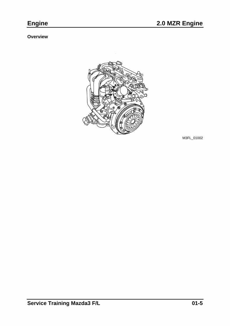
Overview
M3FL_01002
Service Training Mazda3 F/L 01-5
1.6 MZ-CD Engine Engine
1.6 MZ-CD Engine
Features
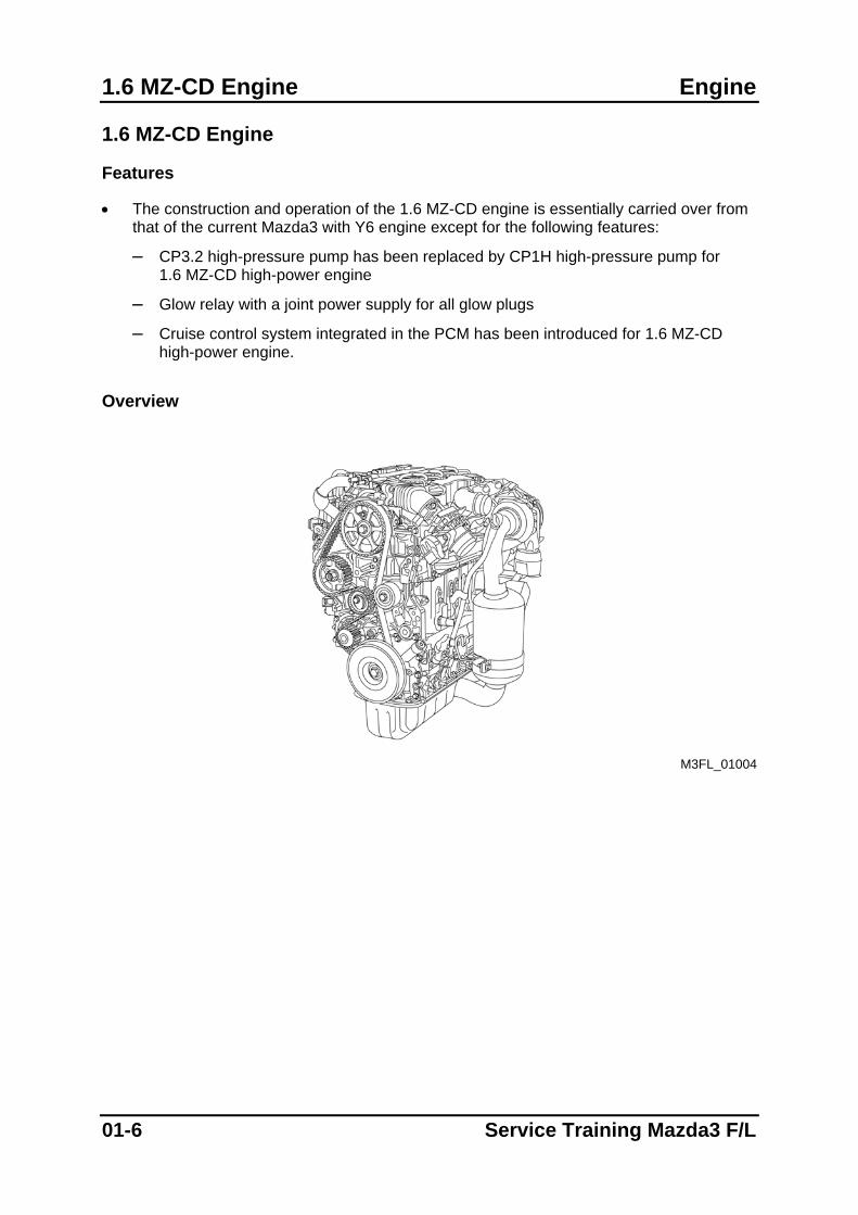
• The construction and operation of the 1.6 MZ-CD engine is essentially carried over from that of the current Mazda3 with Y6 engine except for the following features:
– CP3.2 high-pressure pump has been replaced by CP1H high-pressure pump for 1.6 MZ-CD high-power engine
– Glow relay with a joint power supply for all glow plugs
– Cruise control system integrated in the PCM has been introduced for 1.6 MZ-CD high-power engine.
Overview
M3FL_01004
01-6 Service Training Mazda3 F/L
1.6 MZ-CD Engine Fuel System
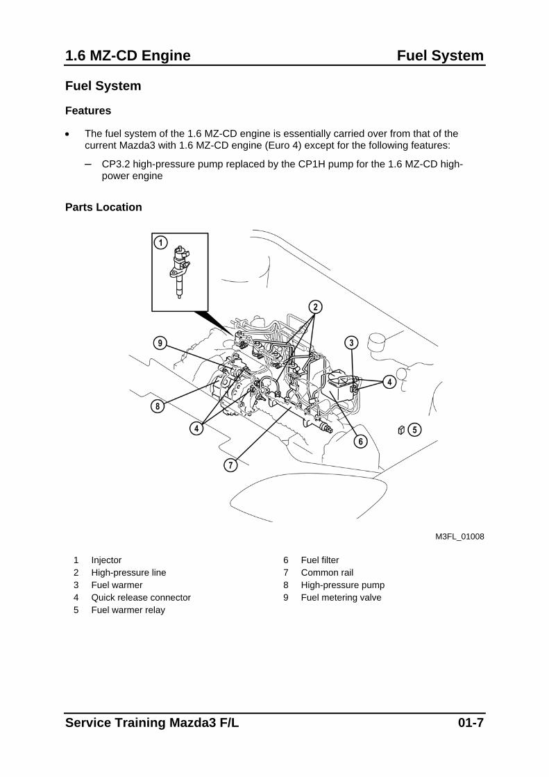
Fuel System
Features
• The fuel system of the 1.6 MZ-CD engine is essentially carried over from that of the current Mazda3 with 1.6 MZ-CD engine (Euro 4) except for the following features:
– CP3.2 high-pressure pump replaced by the CP1H pump for the 1.6 MZ-CD high-power engine
Parts Location
M3FL_01008
1 Injector 6 Fuel filter 2 High-pressure line 7 Common rail 3 Fuel warmer 8 High-pressure pump 4 Quick release connector 9 Fuel metering valve 5 Fuel warmer relay
Service Training Mazda3 F/L 01-7
Fuel System 1.6 MZ-CD Engine
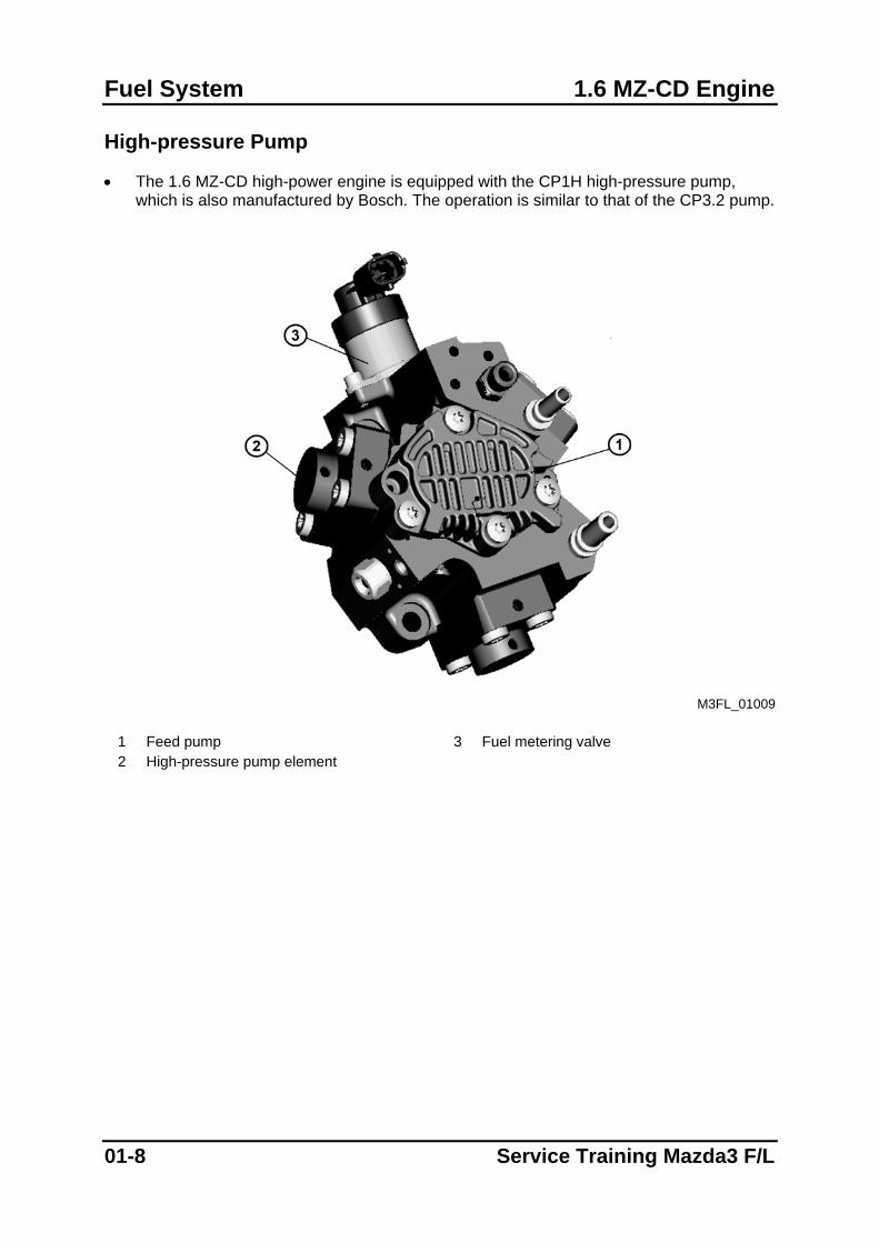
High-pressure Pump
• The 1.6 MZ-CD high-power engine is equipped with the CP1H high-pressure pump, which is also manufactured by Bosch. The operation is similar to that of the CP3.2 pump.
M3FL_01009
1 Feed pump 3 Fuel metering valve 2 High-pressure pump element
01-8 Service Training Mazda3 F/L
1.6 MZ-CD Engine Fuel System
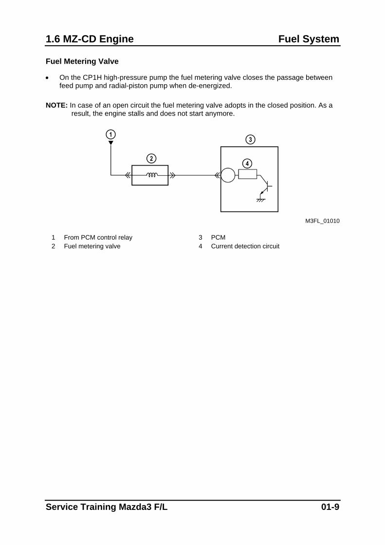
Fuel Metering Valve
• On the CP1H high-pressure pump the fuel metering valve closes the passage between feed pump and radial-piston pump when de-energized.
NOTE: In case of an open circuit the fuel metering valve adopts in the closed position. As a
result, the engine stalls and does not start anymore.
M3FL_01010
1 From PCM control relay 3 PCM 2 Fuel metering valve 4 Current detection circuit
Service Training Mazda3 F/L 01-9
Control System 1.6 MZ-CD Engine
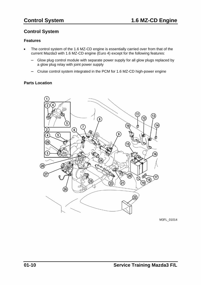
Control System
Features
• The control system of the 1.6 MZ-CD engine is essentially carried over from that of the current Mazda3 with 1.6 MZ-CD engine (Euro 4) except for the following features:
– Glow plug control module with separate power supply for all glow plugs replaced by a glow plug relay with joint power supply
– Cruise control system integrated in the PCM for 1.6 MZ-CD high-power engine Parts Location
M3FL_01014
01-10 Service Training Mazda3 F/L
1.6 MZ-CD Engine Control System
1 Low-power engine 16 Battery 2 High-power engine 17 Starter relay 3 ISV DC motor and position sensor 18 PCM control relay 4 Manifold absolute pressure sensor 19 Glow plug relay 5 IAT sensor no.2 20 MAF/ IAT sensor 6 Injector 21 Engine coolant temperature sensor 7 Camshaft position sensor 22 Powertrain control module (incl.
Barometric pressure sensor) 8 Fuel temperature sensor 23 Fuel pressure sensor 9 EGR valve DC motor and position sensor 24 VBC solenoid valve
10 Accelerator pedal position sensor 25 Crankshaft position sensor 11 Engine switch 26 Exhaust gas temperature sensor (only
high-power engine) 12 Brake pedal position switch 27 Generator 13 Clutch pedal position switch 28 Fuel metering valve 14 DLC-2 29 Charge-air cooler bypass valve DC motor
and position sensor (only high-power engine)
15 DPF differential pressure sensor (only high-power engine)
Service Training Mazda3 F/L 01-11
Control System 1.6 MZ-CD Engine
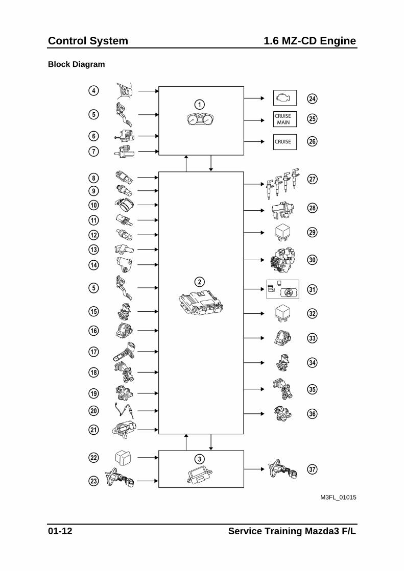
Block Diagram
M3FL_01015
01-12 Service Training Mazda3 F/L
1.6 MZ-CD Engine Control System
1 Instrument cluster 20 Exhaust gas temperature sensor (only
high-power engines) 2 Powertrain control module (incl.
Barometric pressure sensor) 21 DPF differential pressure sensor (only
high-power engines) 3 Fuel additive control module (only high-
power engines) 22 Fuel-filler switch (only high-power
engines) 4 Cruise control switches (only high-power
engines) 23 Fuel additive level sensor (only high-
power engines) 5 Accelerator pedal position sensor 24 Malfunction indicator light 6 Brake pedal position switch 25 Cruise main indicator light 7 Clutch pedal position switch 26 Cruise indicator light 8 Manifold absolute pressure sensor 27 Injectors 9 Fuel pressure sensor 28 VBC solenoid valve
10 MAF/ IAT sensor 29 Glow plug relay 11 Fuel temperature sensor 30 Fuel metering valve 12 Engine coolant temperature sensor 31 Cooling fan and A/C compressor (if
equipped) 13 Camshaft position sensor 32 PCM control relay 14 Crankshaft position sensor 33 Generator (field coil) 15 EGR valve position sensor 34 EGR valve DC motor 16 Generator (stator coil) 35 ISV DC motor (only low-power engines) 17 IAT sensor no. 2 36 ISV DC motor and charge-air cooler
bypass valve DC motor (only high-power engines)
18 ISV position sensor (only low-power engines)
37 Fuel additive pump (only high-power engines)
19 ISV position sensor and charge-air cooler bypass valve position sensor (only high-power engines)
Service Training Mazda3 F/L 01-13
Control System 1.6 MZ-CD Engine
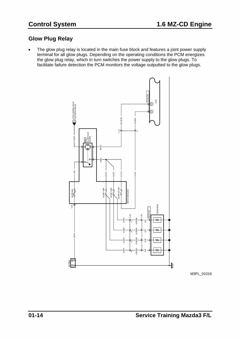
Glow Plug Relay
• The glow plug relay is located in the main fuse block and features a joint power supply terminal for all glow plugs. Depending on the operating conditions the PCM energizes the glow plug relay, which in turn switches the power supply to the glow plugs. To facilitate failure detection the PCM monitors the voltage outputted to the glow plugs.
M3FL_01016
01-14 Service Training Mazda3 F/L
1.6 MZ-CD Engine Control System
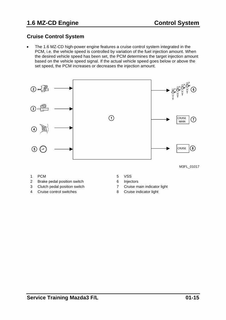
Cruise Control System
• The 1.6 MZ-CD high-power engine features a cruise control system integrated in the PCM, i.e. the vehicle speed is controlled by variation of the fuel injection amount. When the desired vehicle speed has been set, the PCM determines the target injection amount based on the vehicle speed signal. If the actual vehicle speed goes below or above the set speed, the PCM increases or decreases the injection amount.
M3FL_01017
1 PCM 5 VSS 2 Brake pedal position switch 6 Injectors 3 Clutch pedal position switch 7 Cruise main indicator light 4 Cruise control switches 8 Cruise indicator light
Service Training Mazda3 F/L 01-15
Control System 1.6 MZ-CD Engine
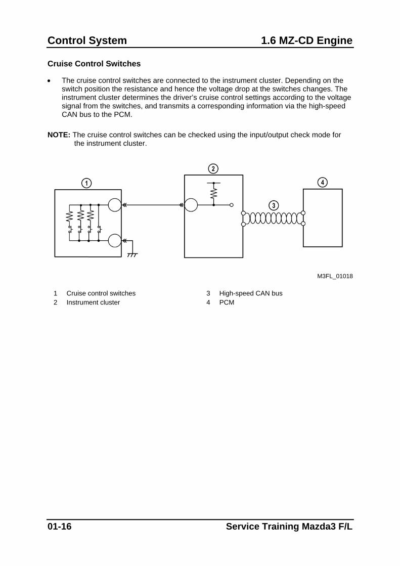
Cruise Control Switches
• The cruise control switches are connected to the instrument cluster. Depending on the switch position the resistance and hence the voltage drop at the switches changes. The instrument cluster determines the driver’s cruise control settings according to the voltage signal from the switches, and transmits a corresponding information via the high-speed CAN bus to the PCM.
NOTE: The cruise control switches can be checked using the input/output check mode for
the instrument cluster.
M3FL_01018
1 Cruise control switches 3 High-speed CAN bus 2 Instrument cluster 4 PCM
01-16 Service Training Mazda3 F/L
Suspension
Suspension
Features
• The construction and operation of the suspension is essentially carried over from that of the current Mazda3 except for the following features:
– Front shock absorbers have been modified
– Front steering knuckle arm position has been modified
– Rear twin-tube shock absorbers replaced by mono-tube shock absorbers with a larger piston diameter (similar to those of the Mazda5)
– Rear lateral link position has been modified
– Rear stabilizer mounting position has been modified
Service Training Mazda3 F/L 02-1
Suspension
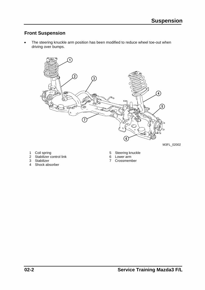
Front Suspension
• The steering knuckle arm position has been modified to reduce wheel toe-out when driving over bumps.
M3FL_02002
1 Coil spring 5 Steering knuckle 2 Stabilizer control link 6 Lower arm 3 Stabilizer 7 Crossmember 4 Shock absorber
02-2 Service Training Mazda3 F/L
Suspension
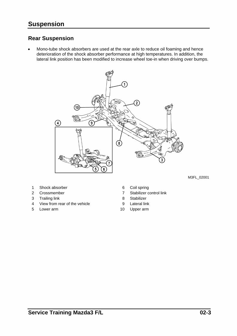
Rear Suspension
• Mono-tube shock absorbers are used at the rear axle to reduce oil foaming and hence deterioration of the shock absorber performance at high temperatures. In addition, the lateral link position has been modified to increase wheel toe-in when driving over bumps.
M3FL_02001
1 Shock absorber 6 Coil spring 2 Crossmember 7 Stabilizer control link 3 Trailing link 8 Stabilizer 4 View from rear of the vehicle 9 Lateral link 5 Lower arm 10 Upper arm
Service Training Mazda3 F/L 02-3
Suspension
Notes
02-4 Service Training Mazda3 F/L
Driveline/Axle
Driveline/Axle
Features
• The construction and operation of the driveline/axle is essentially carried over from that of the current Mazda3 except for the following features:
– Lockbolt for connection between wheel hub and drive shaft replaced by locknut (similar to that of the Mazda5)
– Shape of the joint shaft bracket has been modified (only ZJ/Z6 engine and LF engine)
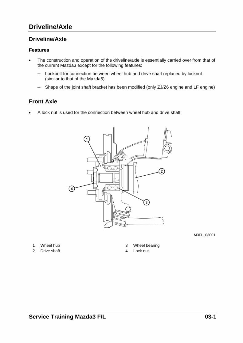
Front Axle
• A lock nut is used for the connection between wheel hub and drive shaft.
M3FL_03001
1 Wheel hub 3 Wheel bearing 2 Drive shaft 4 Lock nut
Service Training Mazda3 F/L 03-1
Driveline/Axle
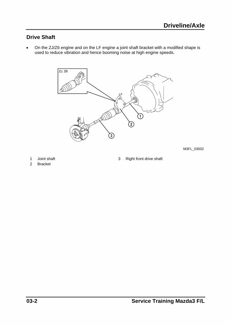
Drive Shaft
• On the ZJ/Z6 engine and on the LF engine a joint shaft bracket with a modified shape is used to reduce vibration and hence booming noise at high engine speeds.
M3FL_03002
1 Joint shaft 3 Right front drive shaft 2 Bracket
03-2 Service Training Mazda3 F/L
Transmission/Transaxle G66M-R Manual Transaxle
G66M-R Manual Transaxle
Features
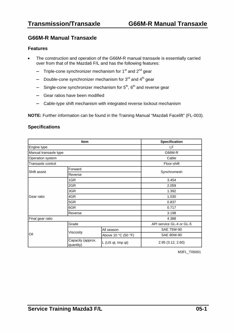
• The construction and operation of the G66M-R manual transaxle is essentially carried over from that of the Mazda6 F/L and has the following features:
– Triple-cone synchronizer mechanism for 1st and 2nd gear
– Double-cone synchronizer mechanism for 3rd and 4th gear
– Single-cone synchronizer mechanism for 5th, 6th and reverse gear
– Gear ratios have been modified
– Cable-type shift mechanism with integrated reverse lockout mechanism NOTE: Further information can be found in the Training Manual “Mazda6 Facelift” (FL-003). Specifications
All seasonAbove 10 °C (50 °F)
Capacity (approx.quantity) L (US qt, Imp qt)
M3FL_T05001
Transaxle control
1GR2GR3GR
Gear ratio
Shift assistForwardReverse
4GR5GR
Final gear ratio3.1984.388
1.0300.8370.7176GR
Reverse
API service GL-4 or GL-5
Oil
Grade
ViscositySAE 80W-90
2.95 (3.12, 2.60)
SAE 75W-90
Floor-shift
Synchromesh
3.454
1.3922.059
Item Specification
G66M-RCable
Engine typeManual transaxle typeOperation system
LF
Service Training Mazda3 F/L 05-1
G66M-R Manual Transaxle Transmission /Transaxle
Overview
M3FL_05001
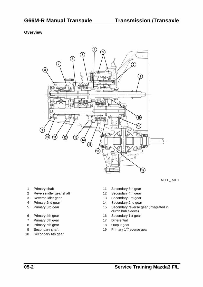
1 Primary shaft 11 Secondary 5th gear 2 Reverse idler gear shaft 12 Secondary 4th gear 3 Reverse idler gear 13 Secondary 3rd gear 4 Primary 2nd gear 14 Secondary 2nd gear 5 Primary 3rd gear 15 Secondary reverse gear (integrated in
clutch hub sleeve) 6 Primary 4th gear 16 Secondary 1st gear 7 Primary 5th gear 17 Differential 8 Primary 6th gear 18 Output gear 9 Secondary shaft 19 Primary 1st/reverse gear
10 Secondary 6th gear
05-2 Service Training Mazda3 F/L
Transmission/Transaxle G66M-R Manual Transaxle
Shift Mechanism
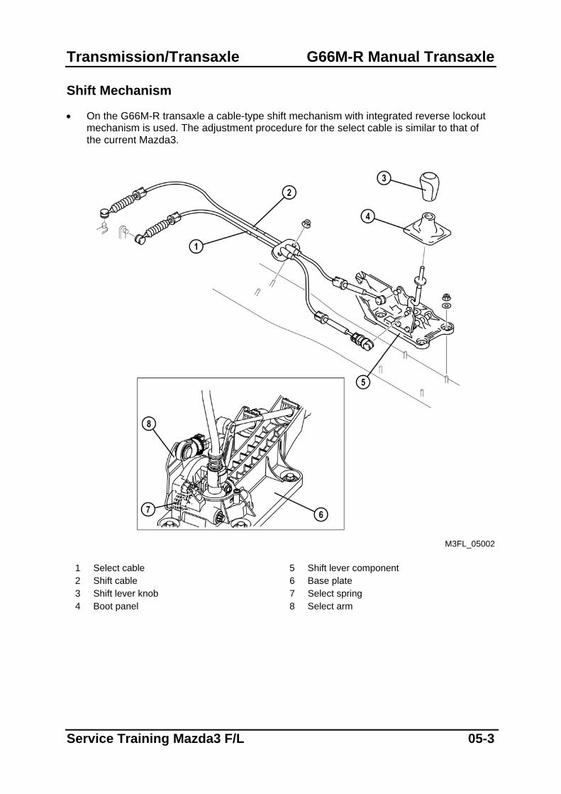
• On the G66M-R transaxle a cable-type shift mechanism with integrated reverse lockout mechanism is used. The adjustment procedure for the select cable is similar to that of the current Mazda3.
M3FL_05002
1 Select cable 5 Shift lever component 2 Shift cable 6 Base plate 3 Shift lever knob 7 Select spring 4 Boot panel 8 Select arm
Service Training Mazda3 F/L 05-3
G66M-R Manual Transaxle Transmission /Transaxle
Reverse Lockout Mechanism
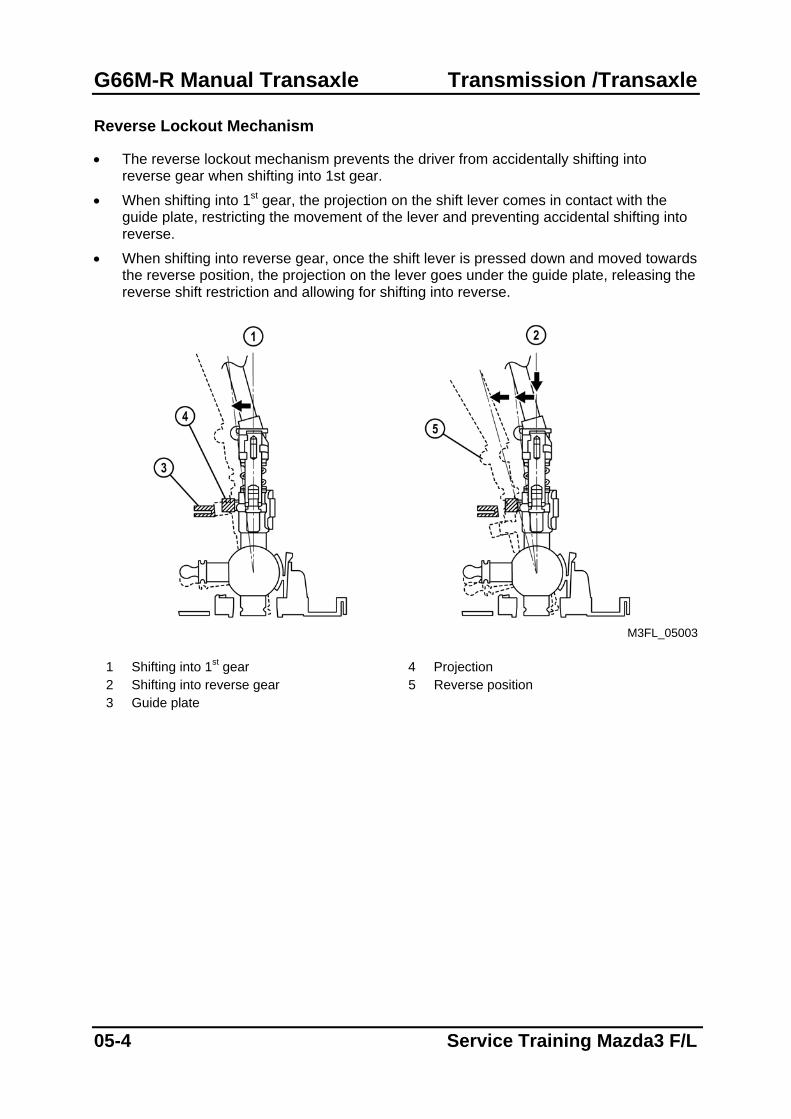
• The reverse lockout mechanism prevents the driver from accidentally shifting into reverse gear when shifting into 1st gear.
• When shifting into 1st gear, the projection on the shift lever comes in contact with the guide plate, restricting the movement of the lever and preventing accidental shifting into reverse.
• When shifting into reverse gear, once the shift lever is pressed down and moved towards the reverse position, the projection on the lever goes under the guide plate, releasing the reverse shift restriction and allowing for shifting into reverse.
M3FL_05003
1 Shifting into 1st gear 4 Projection 2 Shifting into reverse gear 5 Reverse position 3 Guide plate
05-4 Service Training Mazda3 F/L
Transmission/Transaxle FN4A-EL Automatic Transaxle
FN4A-EL Automatic Transaxle
Features
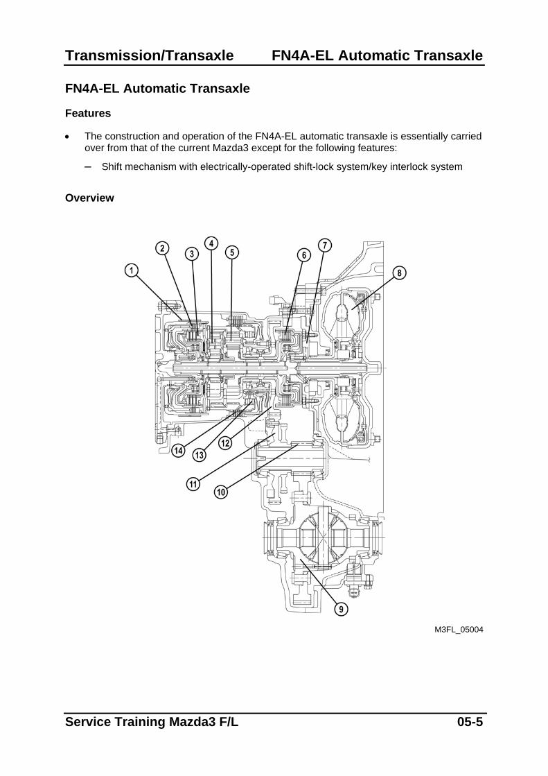
• The construction and operation of the FN4A-EL automatic transaxle is essentially carried over from that of the current Mazda3 except for the following features:
– Shift mechanism with electrically-operated shift-lock system/key interlock system Overview
M3FL_05004
Service Training Mazda3 F/L 05-5
FN4A-EL Automatic Transaxle Transmission/Transaxle
1 2-4 brake band 8 Torque converter 2 Reverse clutch 9 Differential 3 3-4 clutch 10 Output gear 4 Rear planetary gear 11 Secondary gear 5 Front planetary gear 12 Primary gear 6 Forward clutch 13 One-way clutch 7 Oil pump 14 Low and reverse brake
05-6 Service Training Mazda3 F/L
Transmission/Transaxle FN4A-EL Automatic Transaxle
Shift Mechanism
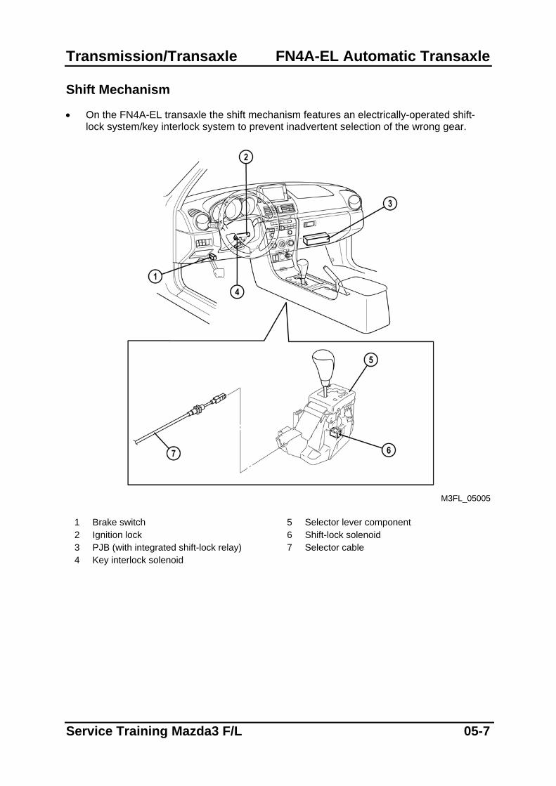
• On the FN4A-EL transaxle the shift mechanism features an electrically-operated shift-lock system/key interlock system to prevent inadvertent selection of the wrong gear.
M3FL_05005
1 Brake switch 5 Selector lever component 2 Ignition lock 6 Shift-lock solenoid 3 PJB (with integrated shift-lock relay) 7 Selector cable 4 Key interlock solenoid
Service Training Mazda3 F/L 05-7
FN4A-EL Automatic Transaxle Transmission/Transaxle
Shift-lock System/Key Interlock System
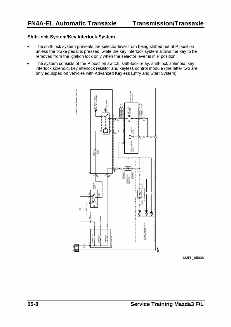
• The shift-lock system prevents the selector lever from being shifted out of P position unless the brake pedal is pressed, while the key interlock system allows the key to be removed from the ignition lock only when the selector lever is in P position.
• The system consists of the P position switch, shift-lock relay, shift-lock solenoid, key interlock solenoid, key interlock resistor and keyless control module (the latter two are only equipped on vehicles with Advanced Keyless Entry and Start System).
M3FL_05006
05-8 Service Training Mazda3 F/L
Transmission/Transaxle FN4A-EL Automatic Transaxle
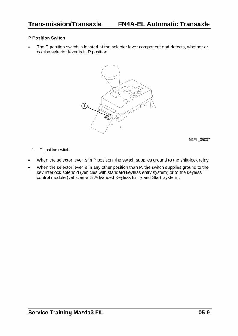
P Position Switch
• The P position switch is located at the selector lever component and detects, whether or not the selector lever is in P position.
M3FL_05007
1 P position switch
• When the selector lever is in P position, the switch supplies ground to the shift-lock relay.
• When the selector lever is in any other position than P, the switch supplies ground to the key interlock solenoid (vehicles with standard keyless entry system) or to the keyless control module (vehicles with Advanced Keyless Entry and Start System).
Service Training Mazda3 F/L 05-9
FN4A-EL Automatic Transaxle Transmission/Transaxle
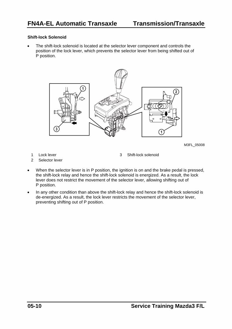
Shift-lock Solenoid
• The shift-lock solenoid is located at the selector lever component and controls the position of the lock lever, which prevents the selector lever from being shifted out of P position.
M3FL_05008
1 Lock lever 3 Shift-lock solenoid 2 Selector lever
• When the selector lever is in P position, the ignition is on and the brake pedal is pressed,
the shift-lock relay and hence the shift-lock solenoid is energized. As a result, the lock lever does not restrict the movement of the selector lever, allowing shifting out of P position.
• In any other condition than above the shift-lock relay and hence the shift-lock solenoid is de-energized. As a result, the lock lever restricts the movement of the selector lever, preventing shifting out of P position.
05-10 Service Training Mazda3 F/L
Transmission/Transaxle FN4A-EL Automatic Transaxle
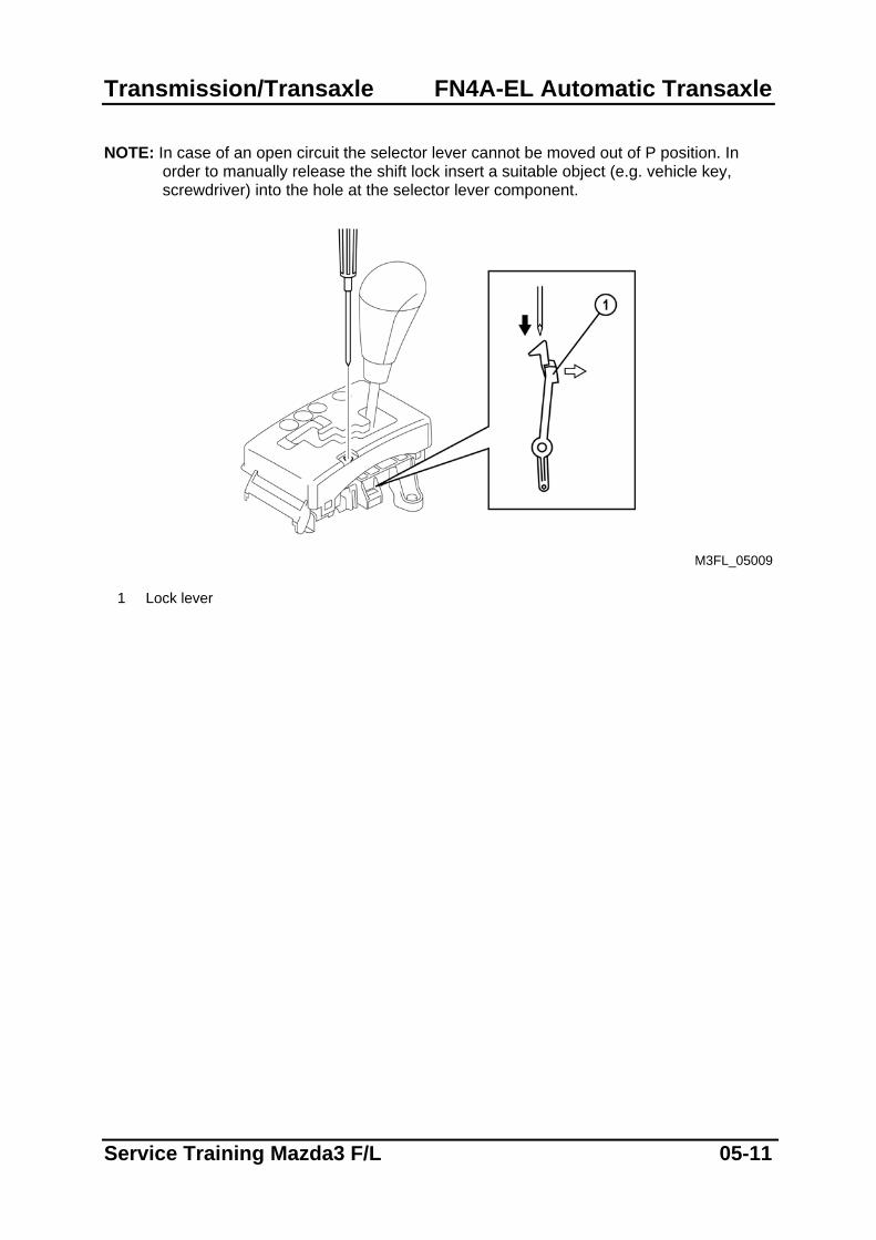
NOTE: In case of an open circuit the selector lever cannot be moved out of P position. In
order to manually release the shift lock insert a suitable object (e.g. vehicle key, screwdriver) into the hole at the selector lever component.
M3FL_05009
1 Lock lever
Service Training Mazda3 F/L 05-11
FN4A-EL Automatic Transaxle Transmission/Transaxle
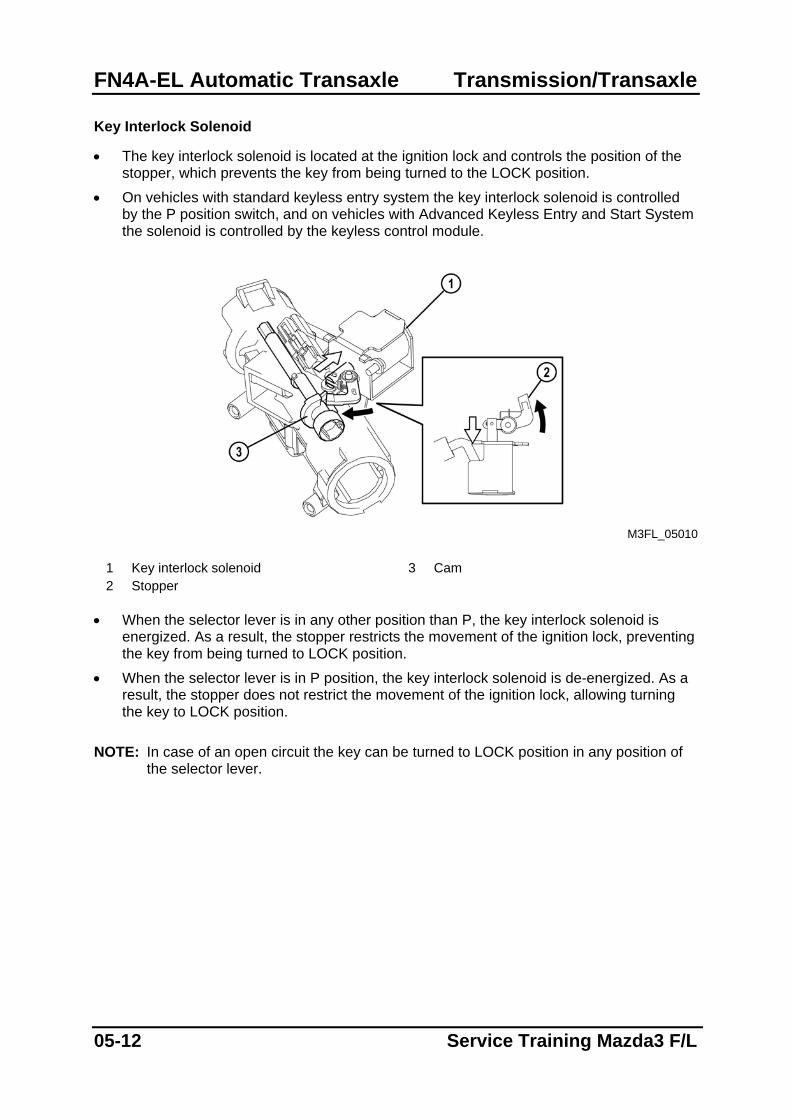
Key Interlock Solenoid
• The key interlock solenoid is located at the ignition lock and controls the position of the stopper, which prevents the key from being turned to the LOCK position.
• On vehicles with standard keyless entry system the key interlock solenoid is controlled by the P position switch, and on vehicles with Advanced Keyless Entry and Start System the solenoid is controlled by the keyless control module.
M3FL_05010
1 Key interlock solenoid 3 Cam 2 Stopper
• When the selector lever is in any other position than P, the key interlock solenoid is
energized. As a result, the stopper restricts the movement of the ignition lock, preventing the key from being turned to LOCK position.
• When the selector lever is in P position, the key interlock solenoid is de-energized. As a result, the stopper does not restrict the movement of the ignition lock, allowing turning the key to LOCK position.
NOTE: In case of an open circuit the key can be turned to LOCK position in any position of
the selector lever.
05-12 Service Training Mazda3 F/L
Restraints Airbag System
Airbag System Features
• The construction and operation of the airbag system is essentially carried over from that of the current Mazda3 except for the following features:
– Cable-type pretensioners integrated in the seat belt buckle have been replaced by ball-type pretensioners integrated in the seat belt retractor (similar to those of the Mazda6 F/L).
– Buckle switch and occupancy sensor on the passenger-side have been introduced for front seat belt reminder system (refer to section 09, Instrumentation/Driver Info).
Service Training Mazda3 F/L 08-1
Airbag System Restraints
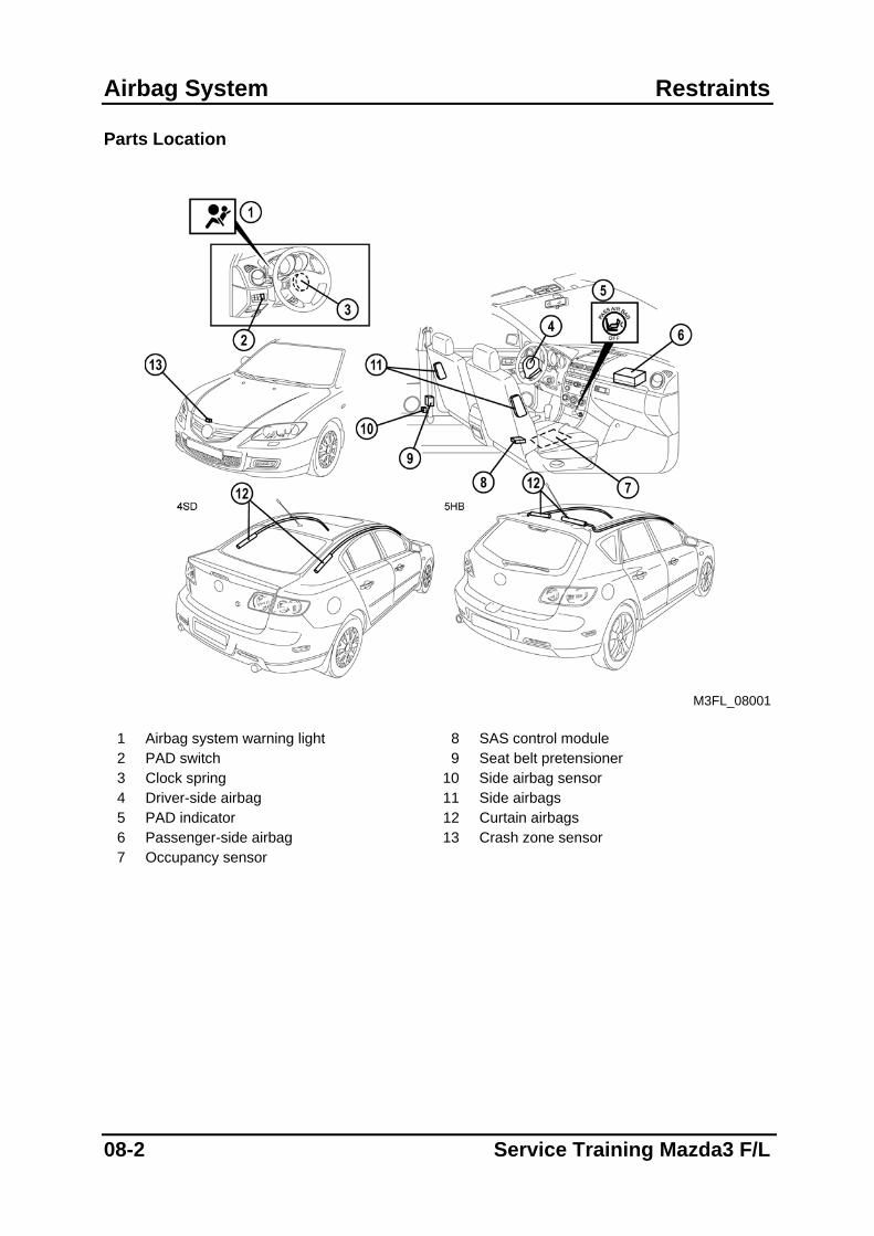
Parts Location
M3FL_08001
1 Airbag system warning light 8 SAS control module 2 PAD switch 9 Seat belt pretensioner 3 Clock spring 10 Side airbag sensor 4 Driver-side airbag 11 Side airbags 5 PAD indicator 12 Curtain airbags 6 Passenger-side airbag 13 Crash zone sensor 7 Occupancy sensor
08-2 Service Training Mazda3 F/L
Restraints Airbag System
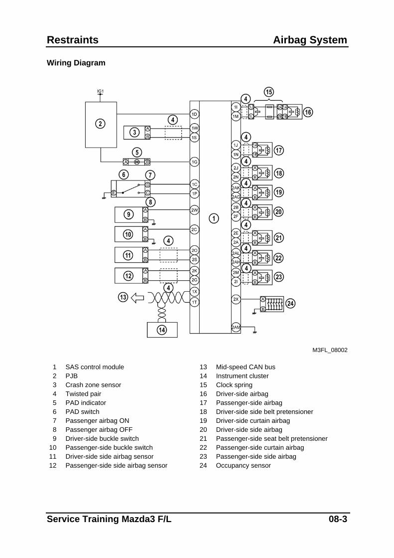
Wiring Diagram
M3FL_08002
1 SAS control module 13 Mid-speed CAN bus 2 PJB 14 Instrument cluster 3 Crash zone sensor 15 Clock spring 4 Twisted pair 16 Driver-side airbag 5 PAD indicator 17 Passenger-side airbag 6 PAD switch 18 Driver-side side belt pretensioner 7 Passenger airbag ON 19 Driver-side curtain airbag 8 Passenger airbag OFF 20 Driver-side side airbag 9 Driver-side buckle switch 21 Passenger-side seat belt pretensioner
10 Passenger-side buckle switch 22 Passenger-side curtain airbag 11 Driver-side side airbag sensor 23 Passenger-side side airbag 12 Passenger-side side airbag sensor 24 Occupancy sensor
Service Training Mazda3 F/L 08-3
Airbag System Restraints
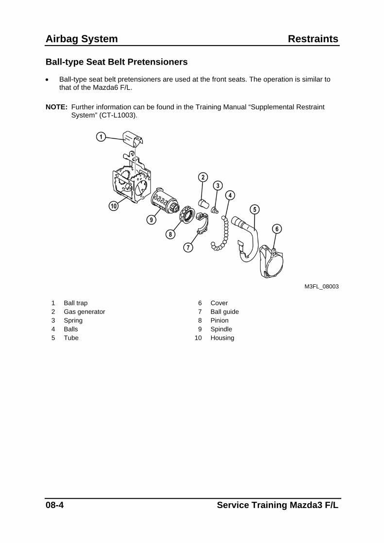
Ball-type Seat Belt Pretensioners
• Ball-type seat belt pretensioners are used at the front seats. The operation is similar to that of the Mazda6 F/L.
NOTE: Further information can be found in the Training Manual “Supplemental Restraint
System” (CT-L1003).
M3FL_08003
1 Ball trap 6 Cover 2 Gas generator 7 Ball guide 3 Spring 8 Pinion 4 Balls 9 Spindle 5 Tube 10 Housing
08-4 Service Training Mazda3 F/L
Body & Accessories Body Panels
Body Panels
Features
• The construction of the body is essentially carried over from that of the current Mazda3 except for the following features:
– Front suspension housings joined to the fender frame by brackets
– Tunnel crossmember no.1 extended to the left and right side members
Front End
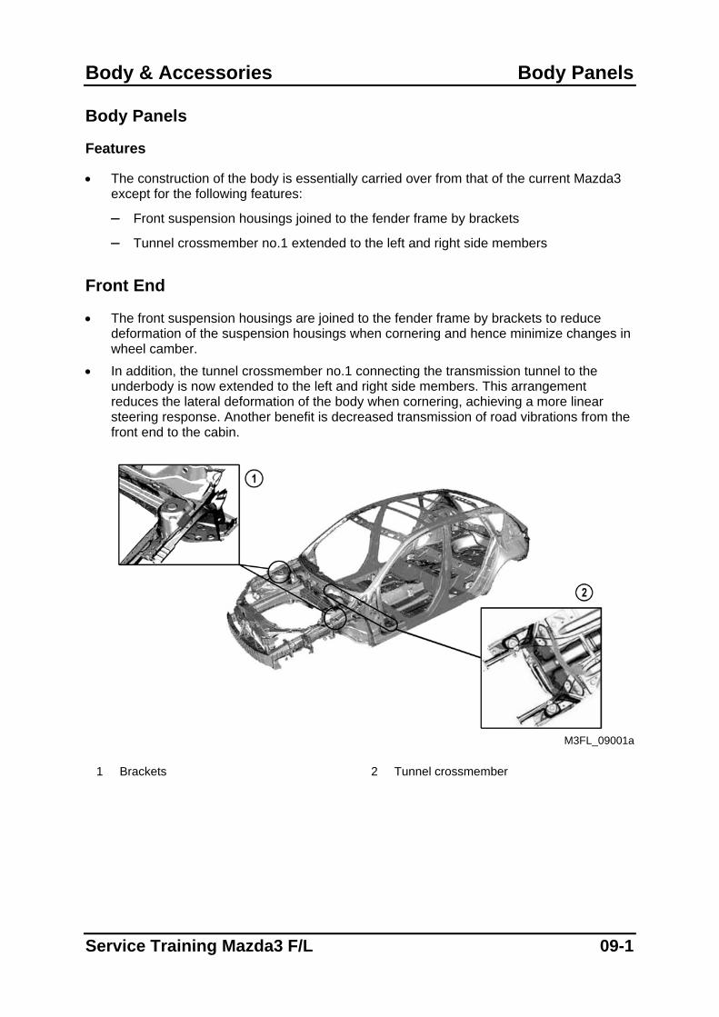
• The front suspension housings are joined to the fender frame by brackets to reduce deformation of the suspension housings when cornering and hence minimize changes in wheel camber.
• In addition, the tunnel crossmember no.1 connecting the transmission tunnel to the underbody is now extended to the left and right side members. This arrangement reduces the lateral deformation of the body when cornering, achieving a more linear steering response. Another benefit is decreased transmission of road vibrations from the front end to the cabin.
M3FL_09001a
1 Brackets 2 Tunnel crossmember
Service Training Mazda3 F/L 09-1
Glass/Windows/Mirrors Body & Accessories
Glass/Windows/Mirrors
Features
• The construction and operation of the glass/windows/mirrors is essentially carried over from that of the current Mazda3 except for the following features:
– Exterior open/close function for the power windows has been introduced (similar to that of the Mazda5).
Exterior Opening/Closing Function
• The power windows feature an exterior open/close function (also termed as global opening/closing function), i.e. all of the windows can either be opened or closed from outside the vehicle. The operation is similar to that of the Mazda5.
NOTE: Further information can be found in the Training Manual “Mazda5” (NMT-007).
09-2 Service Training Mazda3 F/L
Body & Accessories Glass/Windows/Mirrors
Parts Location
M3FL_09001
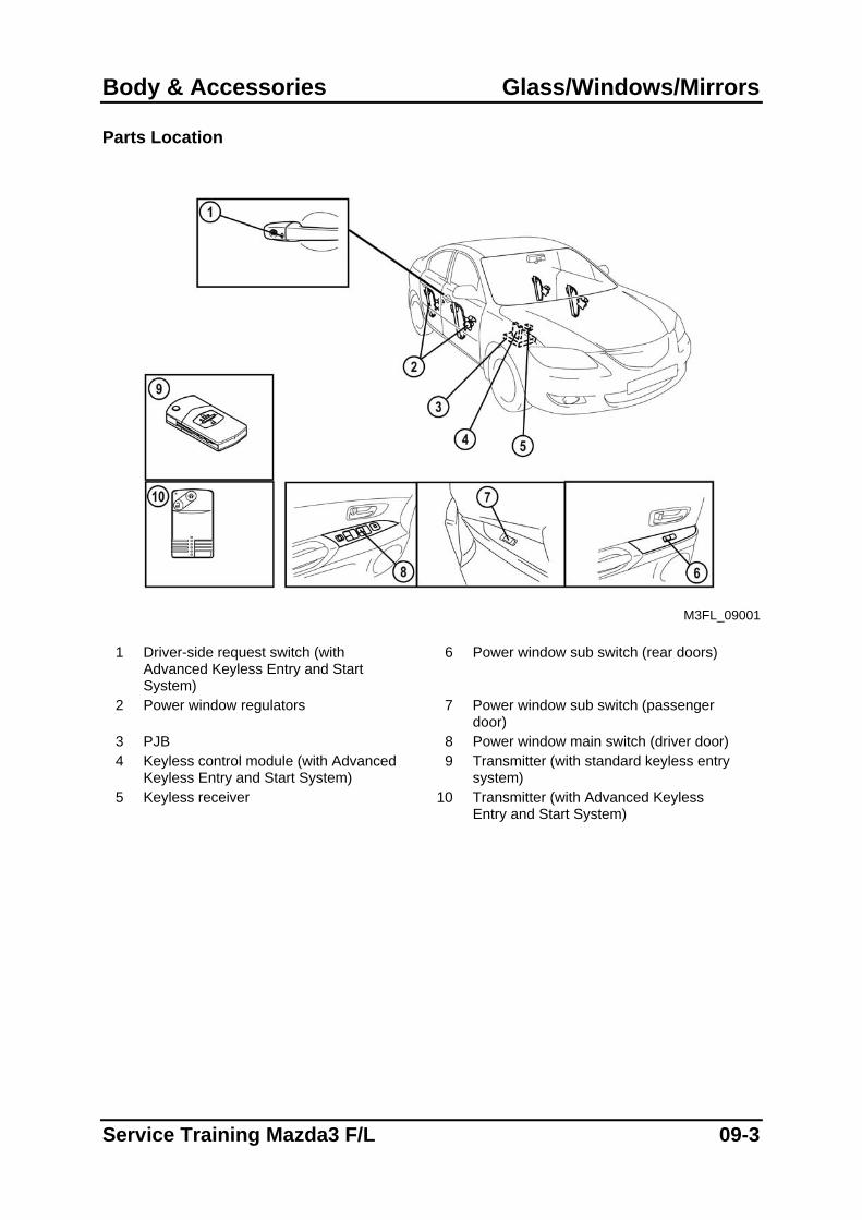
1 Driver-side request switch (with
Advanced Keyless Entry and Start System)
6 Power window sub switch (rear doors)
2 Power window regulators 7 Power window sub switch (passenger door)
3 PJB 8 Power window main switch (driver door) 4 Keyless control module (with Advanced
Keyless Entry and Start System) 9 Transmitter (with standard keyless entry
system) 5 Keyless receiver 10 Transmitter (with Advanced Keyless
Entry and Start System)
Service Training Mazda3 F/L 09-3
Security and Locks Body & Accessories
Security and Locks
Features
• The construction and operation of the security and lock system is essentially carried over from that of the current Mazda3 except for the following features:
– Advanced Keyless Entry and Start System has been introduced (depending on the vehicle grade).
Advanced Keyless Entry and Start System
• The Advanced Keyless Entry and Start System is essentially carried over from that of the Mazda5 and has the following features:
– Card key type transmitter
– Three request switches (trunk lid request switch integrated in the key cylinder push switch on 4SD vehicles)
– Six keyless antennas
– Keyless receiver
– Keyless control module connected to the high-speed CAN bus
– Steering lock unit
– Exterior keyless buzzer
– D-PATS type immobilizer system with control function integrated in the keyless control module
– Instrument cluster is not part of the immobilizer system NOTE: Further information can be found in the Training Manual “Mazda5” (NMT-007).
09-4 Service Training Mazda3 F/L
Body & Accessories Security and Locks
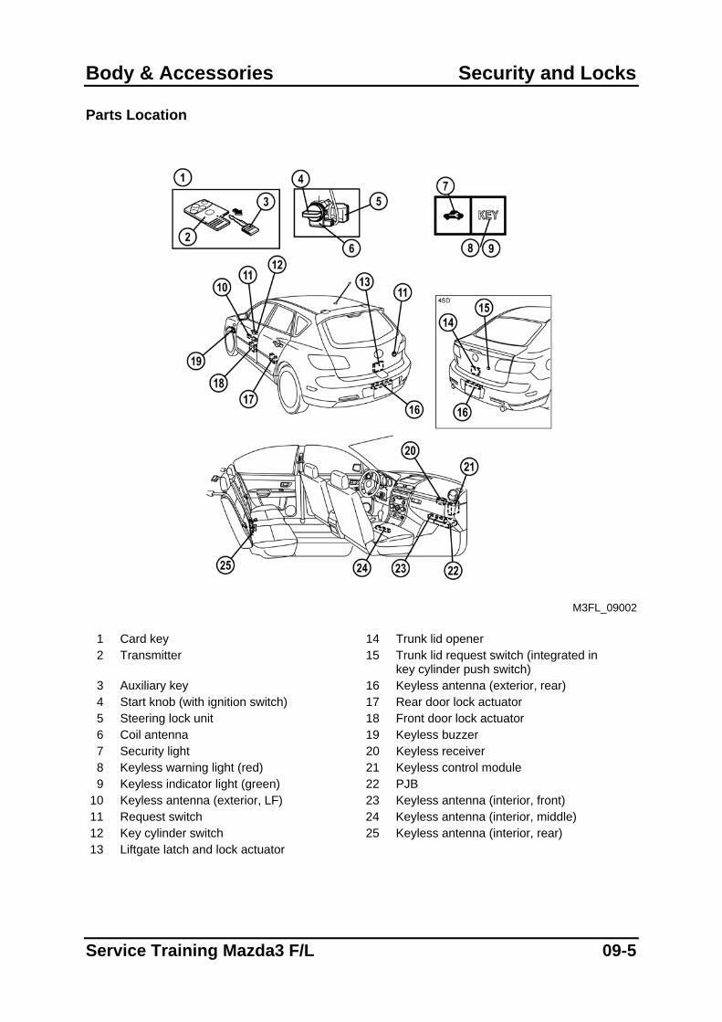
Parts Location
M3FL_09002
1 Card key 14 Trunk lid opener 2 Transmitter 15 Trunk lid request switch (integrated in
key cylinder push switch) 3 Auxiliary key 16 Keyless antenna (exterior, rear) 4 Start knob (with ignition switch) 17 Rear door lock actuator 5 Steering lock unit 18 Front door lock actuator 6 Coil antenna 19 Keyless buzzer 7 Security light 20 Keyless receiver 8 Keyless warning light (red) 21 Keyless control module 9 Keyless indicator light (green) 22 PJB
10 Keyless antenna (exterior, LF) 23 Keyless antenna (interior, front) 11 Request switch 24 Keyless antenna (interior, middle) 12 Key cylinder switch 25 Keyless antenna (interior, rear) 13 Liftgate latch and lock actuator
Service Training Mazda3 F/L 09-5
Security and Locks Body & Accessories
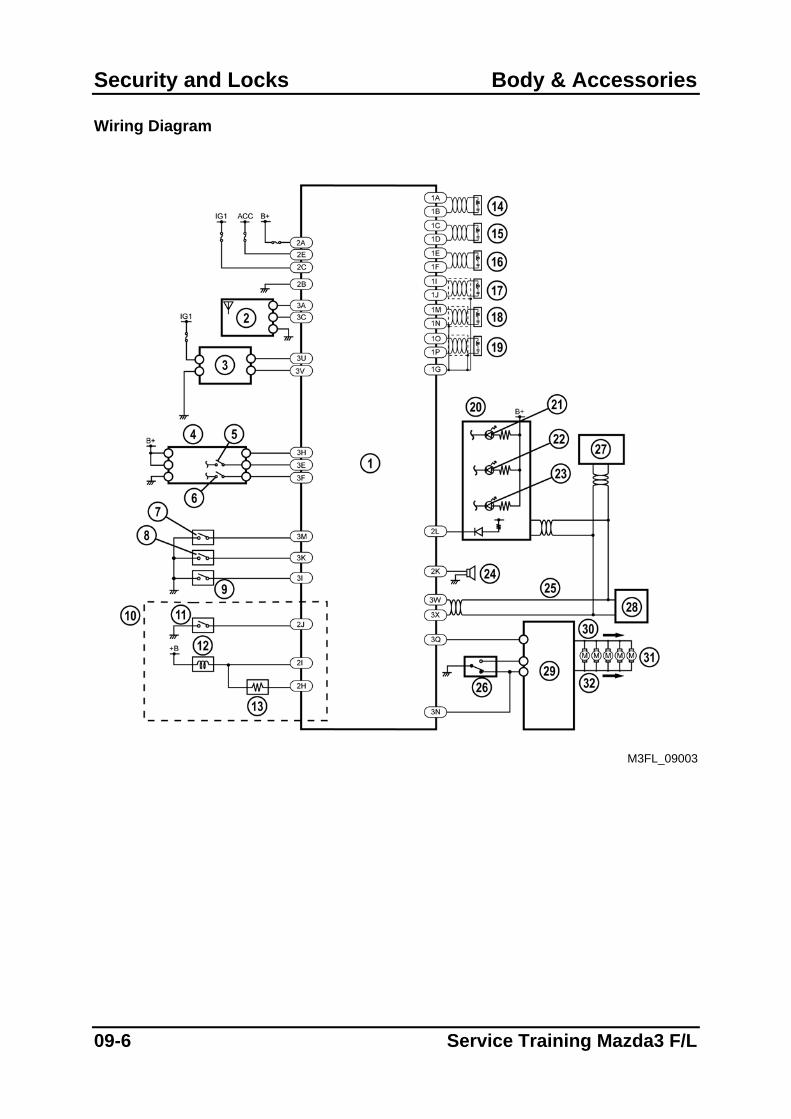
Wiring Diagram
M3FL_09003
09-6 Service Training Mazda3 F/L
Body & Accessories Security and Locks
1 Keyless control module 17 Keyless antenna (interior, rear) 2 Keyless receiver 18 Keyless antenna (interior, middle) 3 Coil antenna 19 Keyless antenna (interior, front) 4 Steering lock unit 20 Instrument cluster 5 Push switch 21 Security light 6 Key reminder switch 22 Keyless warning light (red) 7 Trunk lid/Liftgate request switch 23 Keyless indicator light (green) 8 Request switch (LF) 24 Keyless buzzer 9 Request switch (RF) 25 High-speed CAN bus
10 With ATX 26 Door lock-link switch 11 P position switch 27 PCM 12 Key interlock solenoid 28 DLC-2 13 Key interlock resistor 29 PJB 14 Keyless antenna (exterior, RF) 30 Lock 15 Keyless antenna (exterior, LF) 31 Door lock actuators 16 Keyless antenna (exterior, rear) 32 Unlock
Service Training Mazda3 F/L 09-7
Security and Locks Body & Accessories
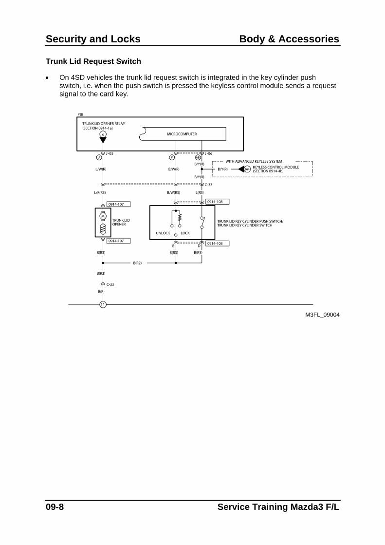
Trunk Lid Request Switch
• On 4SD vehicles the trunk lid request switch is integrated in the key cylinder push switch, i.e. when the push switch is pressed the keyless control module sends a request signal to the card key.
M3FL_09004
09-8 Service Training Mazda3 F/L
Body & Accessories Security and Locks
Keyless Control Module
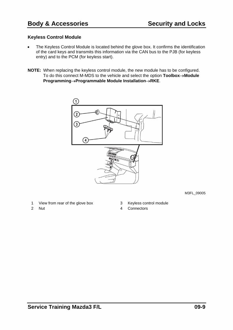
• The Keyless Control Module is located behind the glove box. It confirms the identification of the card keys and transmits this information via the CAN bus to the PJB (for keyless entry) and to the PCM (for keyless start).
NOTE: When replacing the keyless control module, the new module has to be configured.
To do this connect M-MDS to the vehicle and select the option Toolbox→Module Programming→Programmable Module Installation→RKE.
M3FL_09005
1 View from rear of the glove box 3 Keyless control module 2 Nut 4 Connectors
Service Training Mazda3 F/L 09-9
Security and Locks Body & Accessories
Operation
• The operation of the Keyless Entry and Start System is similar to that of the Mazda5. Warning and Guidance Function
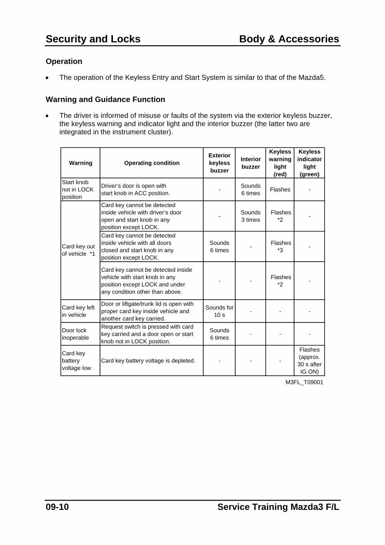
• The driver is informed of misuse or faults of the system via the exterior keyless buzzer, the keyless warning and indicator light and the interior buzzer (the latter two are integrated in the instrument cluster).
Warning Operating conditionExterior keyless buzzer
Interior buzzer
Keylesswarning
light (red)
Keylessindicator
light(green)
Start knobnot in LOCKposition
Driver’s door is open withstart knob in ACC position. - Sounds
6 times Flashes -
Card key cannot be detectedinside vehicle with driver’s dooropen and start knob in anyposition except LOCK.
- Sounds 3 times
Flashes *2 -
Card key cannot be detectedinside vehicle with all doorsclosed and start knob in anyposition except LOCK.
Sounds6 times - Flashes
*3 -
Card key cannot be detected insidevehicle with start knob in anyposition except LOCK and underany condition other than above.
- - Flashes *2 -
Card key left in vehicle
Door or liftgate/trunk lid is open with proper card key inside vehicle and another card key carried.
Sounds for 10 s - - -
Door lockinoperable
Request switch is pressed with card key carried and a door open or start knob not in LOCK position.
Sounds6 times - - -
Card key battery voltage low
Card key battery voltage is depleted. - - -
Flashes (approx.30 s afterIG ON)
M3FL_T09001
Card key outof vehicle *1
09-10 Service Training Mazda3 F/L
Body & Accessories Security and Locks
Guidance Operating conditionExterior keyless buzzer
Interior buzzer
Keylesswarning
light(red)
Keylessindicator
light(green)
Start knoboperable
Start knob is operable (released) when it is pressed. - Sounds
6 times - On(max. 3 s)
Start knobinoperable
Start knob is inoperable (locked)when it is pressed. - Sounds
6 times Flashes -
Lock/unlockanswer back
Doors are locked/unlocked withnormal/advanced keyless entry function.
Locked: Sounds
onceUnlocked:Sounds
twice
- - -
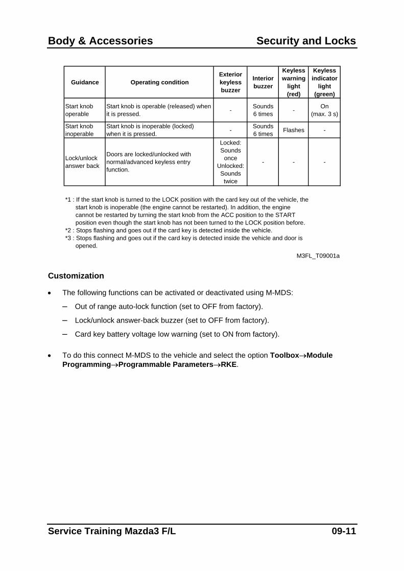
*1 : If the start knob is turned to the LOCK position with the card key out of the vehicle, the start knob is inoperable (the engine cannot be restarted). In addition, the engine cannot be restarted by turning the start knob from the ACC position to the START position even though the start knob has not been turned to the LOCK position before.*2 : Stops flashing and goes out if the card key is detected inside the vehicle.*3 : Stops flashing and goes out if the card key is detected inside the vehicle and door is opened.
M3FL_T09001a Customization
• The following functions can be activated or deactivated using M-MDS:
– Out of range auto-lock function (set to OFF from factory).
– Lock/unlock answer-back buzzer (set to OFF from factory).
– Card key battery voltage low warning (set to ON from factory). • To do this connect M-MDS to the vehicle and select the option Toolbox→Module
Programming→Programmable Parameters→RKE.
Service Training Mazda3 F/L 09-11
Security and Locks Body & Accessories
Service and Repair
Programming additional card keys with two or more card keys
• If two or more registered card keys are available, additional card keys can be programmed without using M-MDS. A maximum of six card keys can be programmed.
NOTE: Do not program card keys while M-MDS or any other computer devices are in the vehicle. Make sure all card keys are operational and have good batteries.
NOTE: Steps 3 to 6 below must be completed within 30 seconds after inserting the auxiliary
key in the ignition lock.
1. Bring the two registered card keys (key 1 and key 2), and the card key to be
programmed into the vehicle and close all doors. 2. Insert auxiliary key in the ignition lock. 3. Turn ignition switch to the ON position. 4. Push the UNLOCK button on card key 1 once. 5. Push the UNLOCK button on card key 2 once. 6. Turn ignition switch to ACC then back to ON three times. 7. Open and close the driver’s door three times. The door lock actuators will lock once,
then unlock to confirm that programming mode is active. 8. Push the UNLOCK button on the card key to be programmed twice. The door lock
actuators will lock once, then unlock to confirm that programming was successful. Programming additional card keys with M-MDS
1. Establish communication between M-MDS and the vehicle.
2. Select the option Toolbox→Body→Security→PATS Functions. 3. Select the option “Program Additional Card Key” and carry out the security access
procedure (read out M-MDS outcode, and input corresponding incode).
09-12 Service Training Mazda3 F/L
Body & Accessories Security and Locks
Erasing registered card keys
1. Establish communication between M-MDS and the vehicle.
2. Select the option Toolbox→Body→Security→PATS Functions. 3. Select the option “Card Key Code Erase” and carry out the security access procedure
(read out the M-MDS outcode, and input corresponding incode). NOTE: After erasing all registered card keys at least one card key must be programmed for
the system to operate correctly.
Steering lock unit programming
• If the steering lock unit is replaced, the new unit must be programmed using M-MDS. NOTE: Do not program the steering lock unit while M-MDS or any other computer devices
are in the vehicle. Make sure all card keys are operational and have good batteries.
NOTE: To program the steering lock unit a registered card key is necessary. If there is no registered card key, perform the card key programming first and then the steering lock unit programming.
1. Bring a registered card key into the vehicle and close all the doors. 2. Establish communication between M-MDS and the vehicle.
3. Select the option Toolbox→Body→Security→PATS Functions. 4. Select the option “Steering Lock Unit Programming” and carry out the security access
procedure (read out the M-MDS outcode, and input corresponding incode).
Service Training Mazda3 F/L 09-13
Security and Locks Body & Accessories
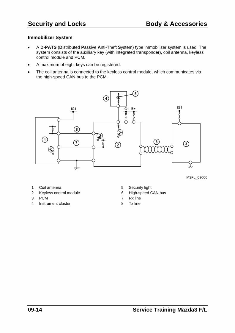
Immobilizer System
• A D-PATS (Distributed Passive Anti-Theft System) type immobilizer system is used. The system consists of the auxiliary key (with integrated transponder), coil antenna, keyless control module and PCM.
• A maximum of eight keys can be registered.
• The coil antenna is connected to the keyless control module, which communicates via the high-speed CAN bus to the PCM.
M3FL_09006
1 Coil antenna 5 Security light 2 Keyless control module 6 High-speed CAN bus 3 PCM 7 Rx line 4 Instrument cluster 8 Tx line
09-14 Service Training Mazda3 F/L
Body & Accessories Security and Locks
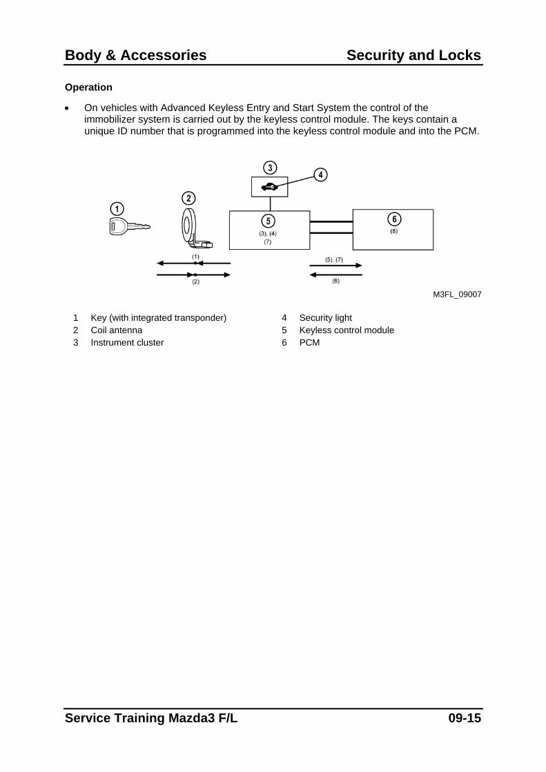
Operation
• On vehicles with Advanced Keyless Entry and Start System the control of the immobilizer system is carried out by the keyless control module. The keys contain a unique ID number that is programmed into the keyless control module and into the PCM.
M3FL_09007
1 Key (with integrated transponder) 4 Security light 2 Coil antenna 5 Keyless control module 3 Instrument cluster 6 PCM
Service Training Mazda3 F/L 09-15
Security and Locks Body & Accessories
UNSATISFACTORYRESULT
SATISFACTORY RESULT
UNSATISFACTORYRESULT
SATISFACTORY RESULT
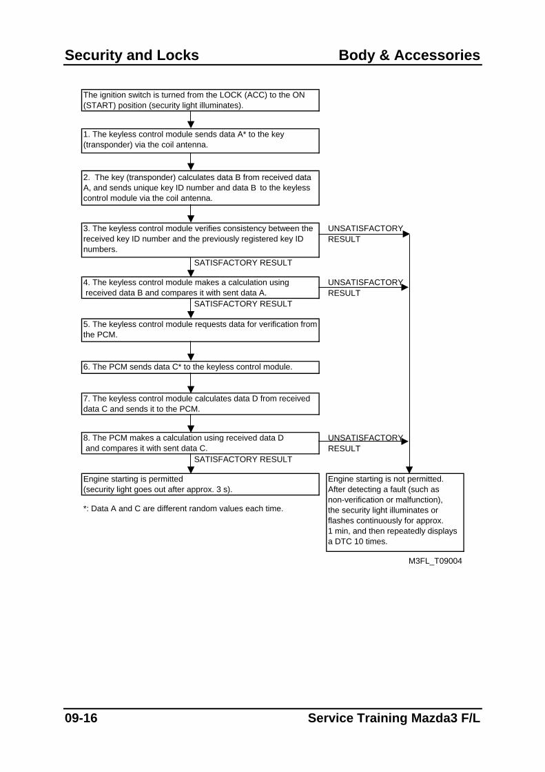
5. The keyless control module requests data for verification from the PCM.
6. The PCM sends data C* to the keyless control module.
UNSATISFACTORYRESULT
SATISFACTORY RESULT
Engine starting is permitted(security light goes out after approx. 3 s).
The ignition switch is turned from the LOCK (ACC) to the ON (START) position (security light illuminates).
3. The keyless control module verifies consistency between the received key ID number and the previously registered key ID numbers.
1. The keyless control module sends data A* to the key (transponder) via the coil antenna.
2. The key (transponder) calculates data B from received data A, and sends unique key ID number and data B to the keyless control module via the coil antenna.
M3FL_T09004
8. The PCM makes a calculation using received data D and compares it with sent data C.
Engine starting is not permitted.After detecting a fault (such asnon-verification or malfunction),the security light illuminates orflashes continuously for approx.1 min, and then repeatedly displays a DTC 10 times.
4. The keyless control module makes a calculation using received data B and compares it with sent data A.
7. The keyless control module calculates data D from received data C and sends it to the PCM.
*: Data A and C are different random values each time.
09-16 Service Training Mazda3 F/L
Body & Accessories Security and Locks
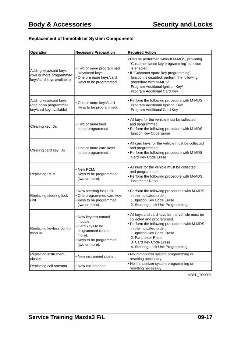
Replacement of Immobilizer System Components
Operation Necessary Preparation Required Action
Adding keys/card keys(two or more programmed keys/card keys available)
• Two or more programmed keys/card keys.• One ore more keys/card keys to be programmed.
• Can be performed without M-MDS, providing "Customer spare key programming" function is enabled.• If "Customer spare key programming" function is disabled, perform the following procedure with M-MDS: Program Additional Ignition Key/ Program Additional Card Key
Adding keys/card keys (one or no programmed key/card key available)
• One or more keys/card keys to be programmed.
• Perform the following procedure with M-MDS: Program Additional Ignition Key/ Program Additional Card Key
Clearing key IDs • Two or more keys to be programmed.
• All keys for the vehicle must be collected and programmed.• Perform the following procedure with M-MDS: Ignition Key Code Erase
Clearing card key IDs • One or more card keys to be programmed.
• All card keys for the vehicle must be collected and programmed.• Perform the following procedure with M-MDS: Card Key Code Erase
Replacing PCM• New PCM.• Keys to be programmed (two or more).
• All keys for the vehicle must be collected and programmed.• Perform the following procedure with M-MDS: Parameter Reset
Replacing steering lockunit
• New steering lock unit.• One programmed card key.• Keys to be programmed (two or more).
• Perform the following procedures with M-MDS in the indicated order: 1. Ignition Key Code Erase 2. Steering Lock Unit Programming
Replacing keyless control module
• New keyless control module.• Card keys to be programmed (one or more).• Keys to be programmed (two or more).
• All keys and card keys for the vehicle must be collected and programmed.• Perform the following procedures with M-MDS in the indicated order: 1. Ignition Key Code Erase 2. Parameter Reset 3. Card Key Code Erase 4. Steering Lock Unit Programming
Replacing instrument cluster • New instrument cluster. • No immobilizer system programming or
resetting necessary.
Replacing coil antenna • New coil antenna. • No immobilizer system programming or resetting necessary.
M3FL_T09005
Service Training Mazda3 F/L 09-17
Security and Locks Body & Accessories
On-board Diagnostic System
• The on-board diagnostic system consists of the following functions:
– Self test
– PID monitor
– Simulation test Self Test
• The self-test function allows the Advanced Keyless Entry and Start System DTCs to be displayed. To do this connect M-MDS to the vehicle and select the option Toolbox→ Self Test→Modules→RKE.
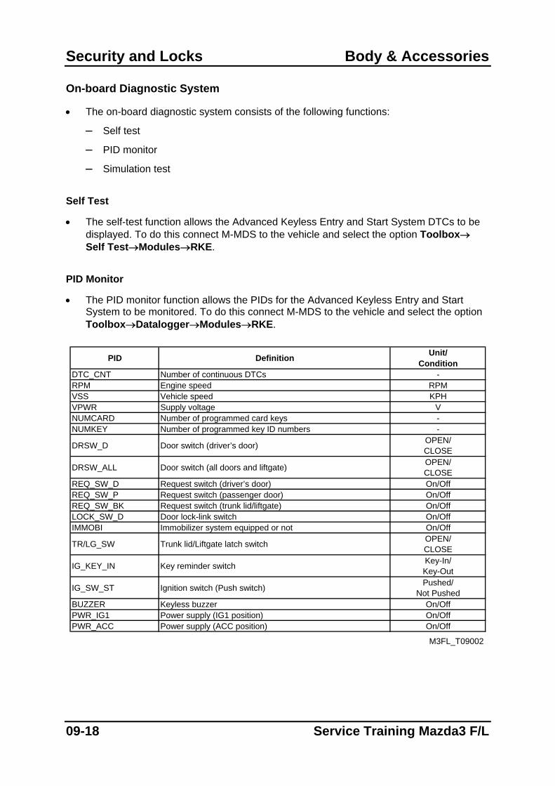
PID Monitor
• The PID monitor function allows the PIDs for the Advanced Keyless Entry and Start System to be monitored. To do this connect M-MDS to the vehicle and select the option Toolbox→Datalogger→Modules→RKE.
PID Definition Unit/
ConditionDTC_CNT Number of continuous DTCs -RPM Engine speed RPMVSS Vehicle speed KPHVPWR Supply voltage VNUMCARD Number of programmed card keys -NUMKEY Number of programmed key ID numbers -
DRSW_D Door switch (driver’s door) OPEN/CLOSE
DRSW_ALL Door switch (all doors and liftgate) OPEN/CLOSE
REQ_SW_D Request switch (driver’s door) On/OffREQ_SW_P Request switch (passenger door) On/OffREQ_SW_BK Request switch (trunk lid/liftgate) On/OffLOCK_SW_D Door lock-link switch On/OffIMMOBI Immobilizer system equipped or not On/Off
TR/LG_SW Trunk lid/Liftgate latch switch OPEN/CLOSE
IG_KEY_IN Key reminder switch Key-In/Key-Out
IG_SW_ST Ignition switch (Push switch) Pushed/Not Pushed
BUZZER Keyless buzzer On/OffPWR_IG1 Power supply (IG1 position) On/OffPWR_ACC Power supply (ACC position) On/Off
M3FL_T09002
09-18 Service Training Mazda3 F/L
Body & Accessories Security and Locks
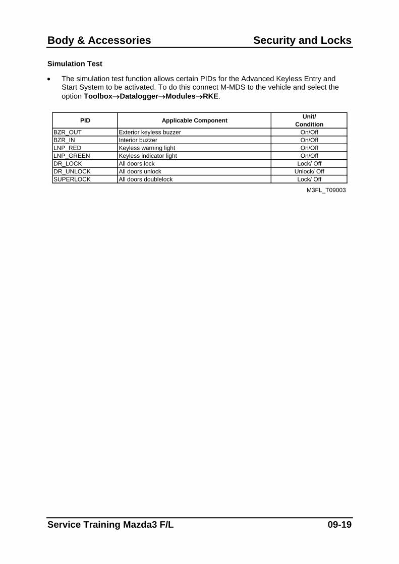
Simulation Test
• The simulation test function allows certain PIDs for the Advanced Keyless Entry and Start System to be activated. To do this connect M-MDS to the vehicle and select the option Toolbox→Datalogger→Modules→RKE.
PID Applicable Component Unit/
ConditionBZR_OUT Exterior keyless buzzer On/OffBZR_IN Interior buzzer On/OffLNP_RED Keyless warning light On/OffLNP_GREEN Keyless indicator light On/OffDR_LOCK All doors lock Lock/ OffDR_UNLOCK All doors unlock Unlock/ OffSUPERLOCK All doors doublelock Lock/ Off
M3FL_T09003
Service Training Mazda3 F/L 09-19
Exterior Trim Body & Accessories
Exterior Trim
Features
• The design of the exterior trim is essentially carried over from that of the current Mazda3 except for the following features:
– New radiator grille design and front/rear bumper design
– New rear combination lamp design (black bezels) and front fog lamp design (the latter one only for Sports Appearance Package)
– New aluminium alloy wheel designs for 15-, 16-, and 17-inch wheels
– Seven new exterior colours (True Red (A4A), Aurora Blue (34J), Galaxy Grey (32S), Icy Blue (33Y), Phantom Blue (32C), Phantom Purple (34N), Crystal White Pearl (34K))
– Modified boot opening design and new boot lid recess for improved accessibility (only 4SD vehicles)
– New underbody tyre deflectors and centre floor cover for improved aerodynamics
09-20 Service Training Mazda3 F/L
Body & Accessories Exterior Trim
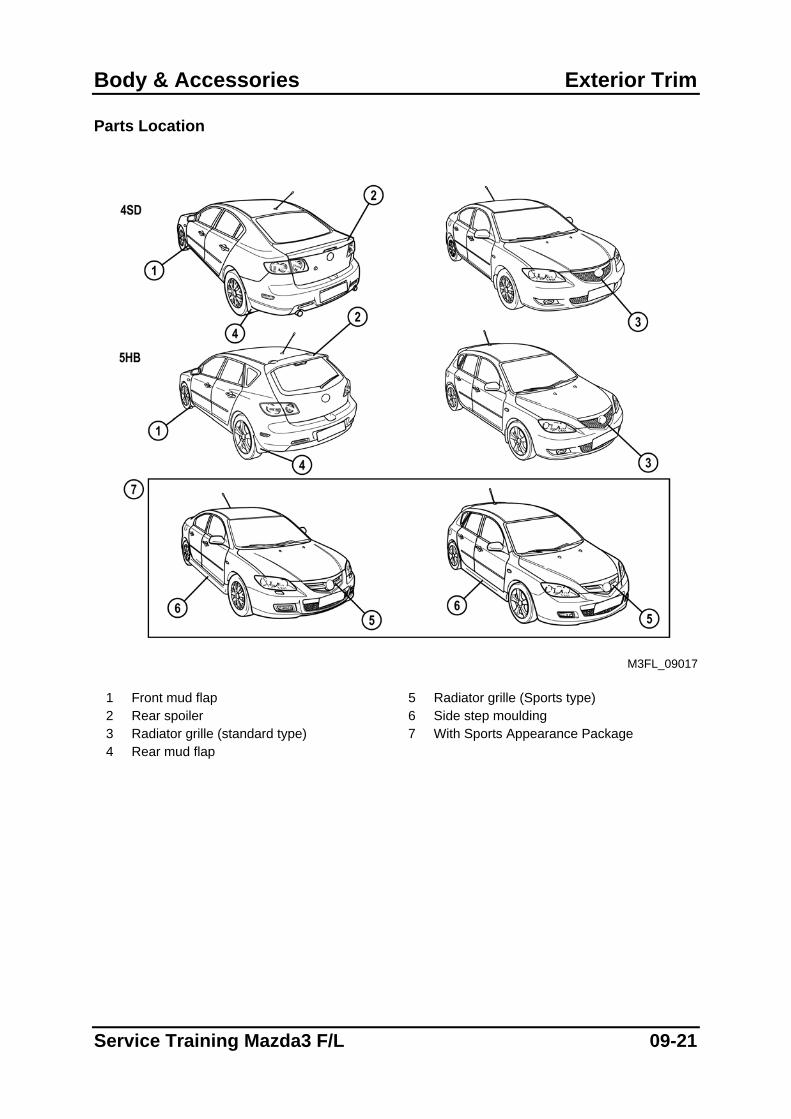
Parts Location
M3FL_09017
1 Front mud flap 5 Radiator grille (Sports type) 2 Rear spoiler 6 Side step moulding 3 Radiator grille (standard type) 7 With Sports Appearance Package 4 Rear mud flap
Service Training Mazda3 F/L 09-21
Interior Trim Body & Accessories
Interior Trim
Features
• The design of the interior trim is essentially carried over from that of the current Mazda3 except for the following features:
– New seat and door trim upholstery materials
– Instrument panel with new Piano Black or Titanium Grey trim (depending on vehicle grade)
– New white driver meters with indirect blue lighting for better readability (depending on vehicle grade)
– New steering wheel adjustment lever design and energy absorbing padding added to steering column to reduce risk of knee injury
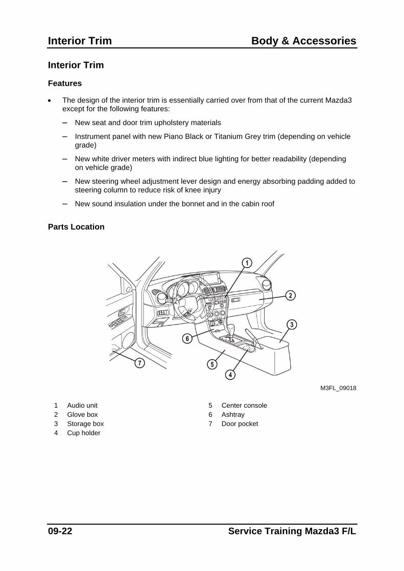
– New sound insulation under the bonnet and in the cabin roof Parts Location
M3FL_09018
1 Audio unit 5 Center console 2 Glove box 6 Ashtray 3 Storage box 7 Door pocket 4 Cup holder
09-22 Service Training Mazda3 F/L
Body & Accessories Lighting Systems
Lighting Systems
Features
• The construction and operation of the lighting systems is essentially carried over from that of the current Mazda3 except for the following features:
– LED brake light/taillight has been added for 4SD vehicles (depending on vehicle grade).
– Headlight auto-leveling control module connected to the DLC-2 (similar to that of the Mazda5)
– Initialization procedure for the headlight auto-leveling control module has been added (similar to that of the Mazda5).
Headlight Auto-leveling System
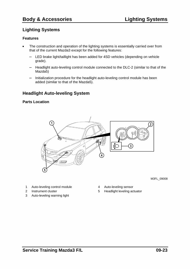
Parts Location
M3FL_09008
1 Auto-leveling control module 4 Auto-leveling sensor 2 Instrument cluster 5 Headlight leveling actuator 3 Auto-leveling warning light
Service Training Mazda3 F/L 09-23
Lighting Systems Body & Accessories
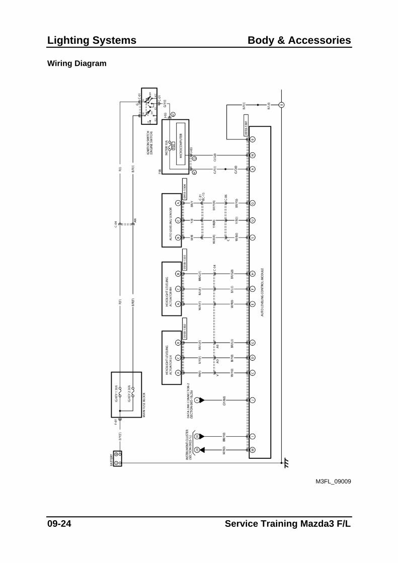
Wiring Diagram
M3FL_09009
09-24 Service Training Mazda3 F/L
Body & Accessories Lighting Systems
Initialization procedure for auto-leveling control module
• An initialization procedure for the auto-leveling control module has been added. When this procedure is activated, the auto-leveling control module detects the height of the unloaded vehicle via the signal from the auto-leveling sensor and stores it as a reference value in the control module memory.
• The auto-leveling control module must be initialized when any of the following procedures has been performed:
– Front combination light replacement
– Auto leveling control module replacement
– Auto leveling sensor removal/installation
– Instrument cluster replacement
– PJB replacement
– Replacement of suspension components or work that effects vehicle height • In order to activate the initialization procedure for the auto-leveling control module,
connect M-MDS to the vehicle and select the option Toolbox→Electrical→Exterior Lighting→Headlamp→Auto-leveling Sensor Re-zero Procedure.
NOTE: In case the initialization procedure using M-MDS is not possible, it can also be
performed by connecting terminal B in the DLC-2 to ground (refer to the workshop manual for the detailed procedure).
Service Training Mazda3 F/L 09-25
Entertainment Body & Accessories
Entertainment Features
• The construction and operation of the entertainment system is essentially carried over from that of the current Mazda3 except for the following features:
– Audio unit with 20 GB music hard disc drive and remote control has been introduced (similar to that of the Mazda5).
Audio System
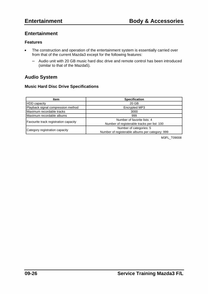
Music Hard Disc Drive Specifications
Item Specification
HDD capacity 20 GBPlayback signal compression method Encrypted MP3Maximum recordable tracks 3000Maximum recordable albums 999
Favourite track registration capacity Number of favorite lists: 4Number of registerable tracks per list: 100
Category registration capacity Number of categories: 5Number of registerable albums per category: 999
M3FL_T09008
09-26 Service Training Mazda3 F/L
Body & Accessories Entertainment
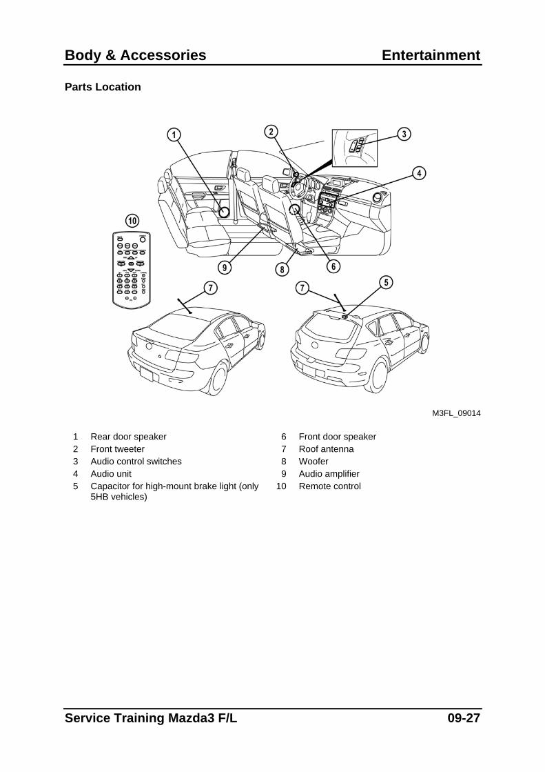
Parts Location
M3FL_09014
1 Rear door speaker 6 Front door speaker 2 Front tweeter 7 Roof antenna 3 Audio control switches 8 Woofer 4 Audio unit 9 Audio amplifier 5 Capacitor for high-mount brake light (only
5HB vehicles) 10 Remote control
Service Training Mazda3 F/L 09-27
Entertainment Body & Accessories
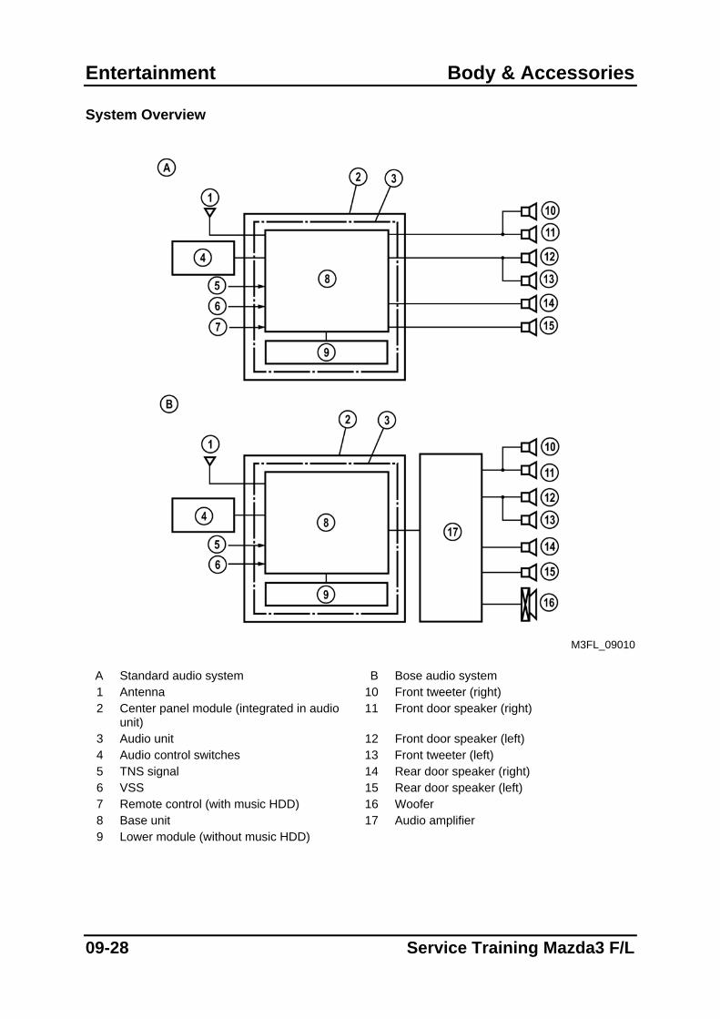
System Overview
M3FL_09010
A Standard audio system B Bose audio system 1 Antenna 10 Front tweeter (right) 2 Center panel module (integrated in audio
unit) 11 Front door speaker (right)
3 Audio unit 12 Front door speaker (left) 4 Audio control switches 13 Front tweeter (left) 5 TNS signal 14 Rear door speaker (right) 6 VSS 15 Rear door speaker (left) 7 Remote control (with music HDD) 16 Woofer 8 Base unit 17 Audio amplifier 9 Lower module (without music HDD)
09-28 Service Training Mazda3 F/L
Body & Accessories Entertainment
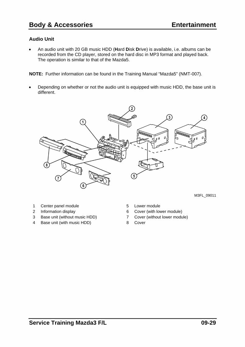
Audio Unit
• An audio unit with 20 GB music HDD (Hard Disk Drive) is available, i.e. albums can be recorded from the CD player, stored on the hard disc in MP3 format and played back. The operation is similar to that of the Mazda5.
NOTE: Further information can be found in the Training Manual “Mazda5” (NMT-007).
• Depending on whether or not the audio unit is equipped with music HDD, the base unit is
different.
M3FL_09011
1 Center panel module 5 Lower module 2 Information display 6 Cover (with lower module) 3 Base unit (without music HDD) 7 Cover (without lower module) 4 Base unit (with music HDD) 8 Cover
Service Training Mazda3 F/L 09-29
Instrumentation/Driver Info Body & Accessories
Instrumentation/Driver Info
Features
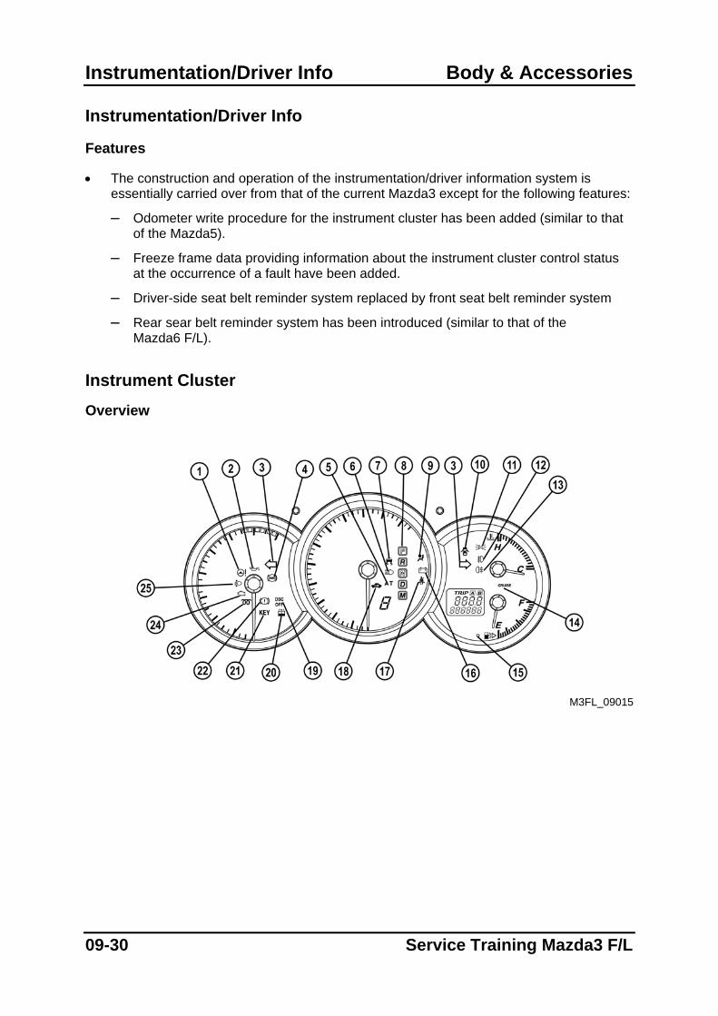
• The construction and operation of the instrumentation/driver information system is essentially carried over from that of the current Mazda3 except for the following features:
– Odometer write procedure for the instrument cluster has been added (similar to that of the Mazda5).
– Freeze frame data providing information about the instrument cluster control status at the occurrence of a fault have been added.
– Driver-side seat belt reminder system replaced by front seat belt reminder system
– Rear sear belt reminder system has been introduced (similar to that of the Mazda6 F/L).
Instrument Cluster
Overview
M3FL_09015
09-30 Service Training Mazda3 F/L
Body & Accessories Instrumentation/Driver Info
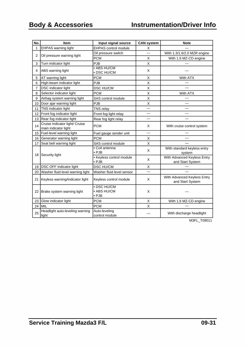
No. Item Input signal source CAN system Note1 EHPAS warning light EHPAS control module X —
Oil pressure switch — With 1.3/1.6/2.0 MZR enginePCM X With 1.6 MZ-CD engine
3 Turn indicator light PJB X —
4 ABS warning light• ABS HU/CM• DSC HU/CM X —
5 AT warning light PCM X With ATX6 High-beam indicator light PJB X —7 DSC indicator light DSC HU/CM X —8 Selector indicator light PCM X With ATX9 Airbag system warning light SAS control module X —
10 Door ajar warning light PJB X —11 TNS indicator light TNS relay — —12 Front fog indicator light Front fog light relay — —13 Rear fog indicator light Rear fog light relay — —
14 Cruise indicator light/ Cruise main indicator light PCM X With cruise control system
15 Fuel-level warning light Fuel gauge sender unit — —16 Generator warning light PCM X —17 Seat belt warning light SAS control module X —
• Coil antenna• PJB X With standard keyless entry
system• Keyless control module• PJB X With Advanced Keyless Entry
and Start System19 DSC OFF indicator light DSC HU/CM X —20 Washer fluid level warning light Washer fluid level sensor — —
22 Brake system warning light• DSC HU/CM• ABS HU/CM• PJB
X —
23 Glow indicator light PCM X With 1.6 MZ-CD engine24 MIL PCM X —
25 Headlight auto-leveling warninglight
Auto-leveling control module — With discharge headlight
M3FL_T09011
XKeyless control module With Advanced Keyless Entry and Start System
2 Oil pressure warning light
21 Keyless warning/indicator light
18 Security light
Service Training Mazda3 F/L 09-31
Instrumentation/Driver Info Body & Accessories
Odometer Write Procedure
• An odometer write procedure for the instrument cluster has been added. When configuring a new instrument cluster with M-MDS, the total mileage logged in the old cluster is automatically uploaded to the new cluster. To do this, connect M-MDS to the vehicle and select the option Toolbox→Module Programming→Programmable Module Installation→IC.
• The odometer write procedure can only be conducted once. However, the new instrument cluster must display less than 100 km for the mileage data to be uploaded. If a cluster with 100 km or more is configured, M-MDS will display an error message after configuring, indicating that the procedure failed. In this situation, all data other than the mileage will have been uploaded into the new instrument cluster, so that the configuration is actually successful.
• In order to upload the mileage data to a new instrument cluster with an odometer setting of 100 km or more, perform the odometer write procedure after completing the instrument cluster configuration. To do this select the option Toolbox→Module Programming→Programmable Parameters→Odometer Write. During this procedure M-MDS will request the user to input As-built data (VIN and Vehicle Data).
NOTE: Do NOT delete the M-MDS session until the odometer write procedure is completed.
Otherwise it is not possible anymore to upload the mileage data to the new instrument cluster.
NOTE: In case the old instrument cluster is electrically damaged and therefore the
configuration data cannot be read, the odometer write procedure cannot be performed.
09-32 Service Training Mazda3 F/L
Body & Accessories Instrumentation/Driver Info
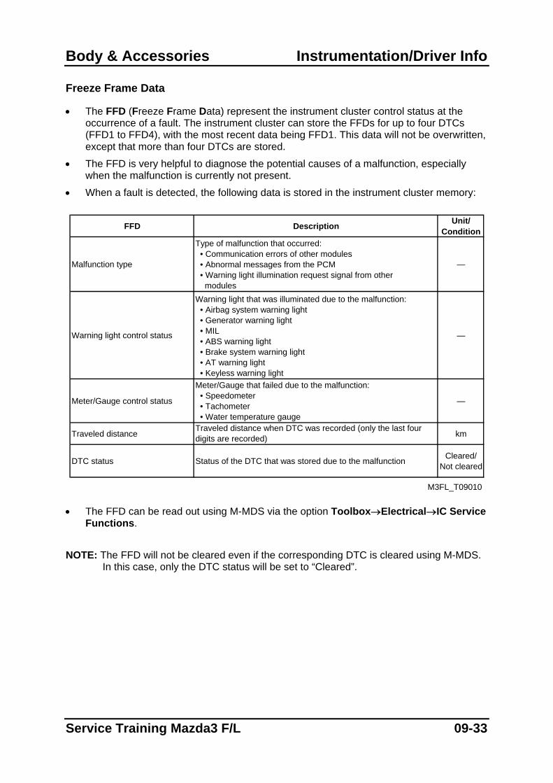
Freeze Frame Data
• The FFD (Freeze Frame Data) represent the instrument cluster control status at the occurrence of a fault. The instrument cluster can store the FFDs for up to four DTCs (FFD1 to FFD4), with the most recent data being FFD1. This data will not be overwritten, except that more than four DTCs are stored.
• The FFD is very helpful to diagnose the potential causes of a malfunction, especially when the malfunction is currently not present.
• When a fault is detected, the following data is stored in the instrument cluster memory:
FFD Description Unit/ Condition
Malfunction type
Type of malfunction that occurred: • Communication errors of other modules • Abnormal messages from the PCM • Warning light illumination request signal from other modules
—
Warning light control status
Warning light that was illuminated due to the malfunction: • Airbag system warning light • Generator warning light • MIL • ABS warning light • Brake system warning light • AT warning light • Keyless warning light
—
Meter/Gauge control status
Meter/Gauge that failed due to the malfunction: • Speedometer • Tachometer • Water temperature gauge
—
Traveled distanceTraveled distance when DTC was recorded (only the last four digits are recorded) km
DTC status Status of the DTC that was stored due to the malfunction Cleared/Not cleared
M3FL_T09010 • The FFD can be read out using M-MDS via the option Toolbox→Electrical→IC Service
Functions. NOTE: The FFD will not be cleared even if the corresponding DTC is cleared using M-MDS.
In this case, only the DTC status will be set to “Cleared”.
Service Training Mazda3 F/L 09-33
Instrumentation/Driver Info Body & Accessories
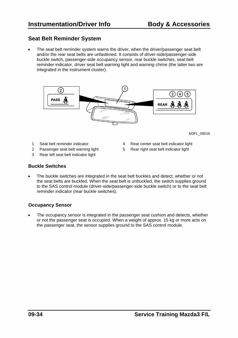
Seat Belt Reminder System
• The seat belt reminder system warns the driver, when the driver/passenger seat belt and/or the rear seat belts are unfastened. It consists of driver-side/passenger-side buckle switch, passenger-side occupancy sensor, rear buckle switches, seat belt reminder indicator, driver seat belt warning light and warning chime (the latter two are integrated in the instrument cluster).
M3FL_09016
1 Seat belt reminder indicator 4 Rear center seat belt indicator light 2 Passenger seat belt warning light 5 Rear right seat belt indicator light 3 Rear left seat belt indicator light
Buckle Switches
• The buckle switches are integrated in the seat belt buckles and detect, whether or not the seat belts are buckled. When the seat belt is unbuckled, the switch supplies ground to the SAS control module (driver-side/passenger-side buckle switch) or to the seat belt reminder indicator (rear buckle switches).
Occupancy Sensor
• The occupancy sensor is integrated in the passenger seat cushion and detects, whether or not the passenger seat is occupied. When a weight of approx. 15 kg or more acts on the passenger seat, the sensor supplies ground to the SAS control module.
09-34 Service Training Mazda3 F/L
Body & Accessories Instrumentation/Driver Info
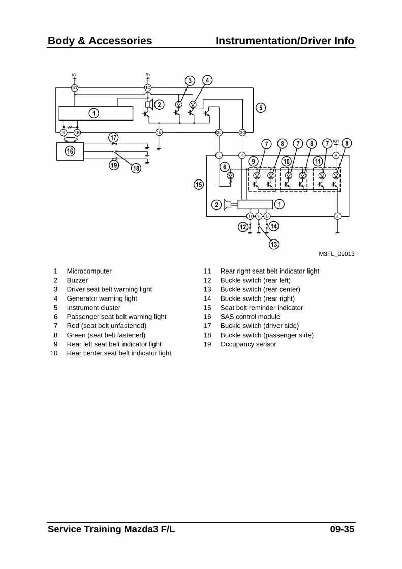
M3FL_09013
1 Microcomputer 11 Rear right seat belt indicator light 2 Buzzer 12 Buckle switch (rear left) 3 Driver seat belt warning light 13 Buckle switch (rear center) 4 Generator warning light 14 Buckle switch (rear right) 5 Instrument cluster 15 Seat belt reminder indicator 6 Passenger seat belt warning light 16 SAS control module 7 Red (seat belt unfastened) 17 Buckle switch (driver side) 8 Green (seat belt fastened) 18 Buckle switch (passenger side) 9 Rear left seat belt indicator light 19 Occupancy sensor
10 Rear center seat belt indicator light
Service Training Mazda3 F/L 09-35
Instrumentation/Driver Info Body & Accessories
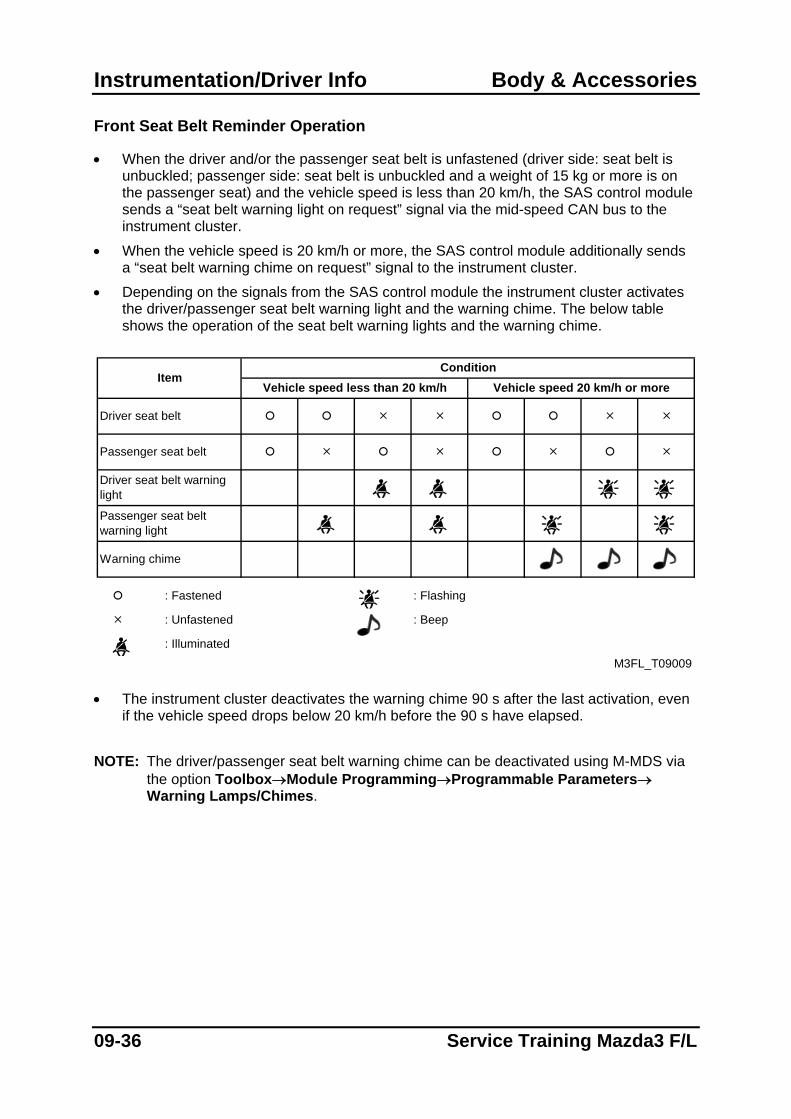
Front Seat Belt Reminder Operation
• When the driver and/or the passenger seat belt is unfastened (driver side: seat belt is unbuckled; passenger side: seat belt is unbuckled and a weight of 15 kg or more is on the passenger seat) and the vehicle speed is less than 20 km/h, the SAS control module sends a “seat belt warning light on request” signal via the mid-speed CAN bus to the instrument cluster.
• When the vehicle speed is 20 km/h or more, the SAS control module additionally sends a “seat belt warning chime on request” signal to the instrument cluster.
• Depending on the signals from the SAS control module the instrument cluster activates the driver/passenger seat belt warning light and the warning chime. The below table shows the operation of the seat belt warning lights and the warning chime.
M3FL_T09009
Condition
: Flashing
: Beep
Vehicle speed less than 20 km/h Vehicle speed 20 km/h or more
Warning chime
: Fastened
: Unfastened
: Illuminated
Passenger seat belt warning light
Item
Driver seat belt
Passenger seat belt
Driver seat belt warning light
• The instrument cluster deactivates the warning chime 90 s after the last activation, even
if the vehicle speed drops below 20 km/h before the 90 s have elapsed. NOTE: The driver/passenger seat belt warning chime can be deactivated using M-MDS via
the option Toolbox→Module Programming→Programmable Parameters→ Warning Lamps/Chimes.
09-36 Service Training Mazda3 F/L
Body & Accessories Instrumentation/Driver Info
NOTE: The passenger seat belt warning light can be checked using the input/output check
mode for the instrument cluster.
Rear Seat Belt Reminder Operation
• The seat belt reminder indicator activates all rear seat belt indicator lights after the ignition is switched on, or when the rear seat belts are unfastened or fastened while the engine is running. The colour of the indicator light provides information about the status of the seat belts:
– If the indicator light is illuminated in red, the corresponding seat belt is unfastened (seat belt is unbuckled).
– If the indicator light is illuminated in green, the corresponding seat belt is fastened (seat belt is buckled).
• In addition, the warning chime of the seat belt reminder indicator sounds for 0.5 s, when
a seat belt is unfastened while the engine is running.
• The seat belt reminder indicator deactivates all rear seat belt indicator lights either 40 s after engine start (i.e. after the generator warning light is off) or 40 s after the last activation (in case the indicator lights have been activated while the engine is running).
Service Training Mazda3 F/L 09-37
Control System Body & Accessories
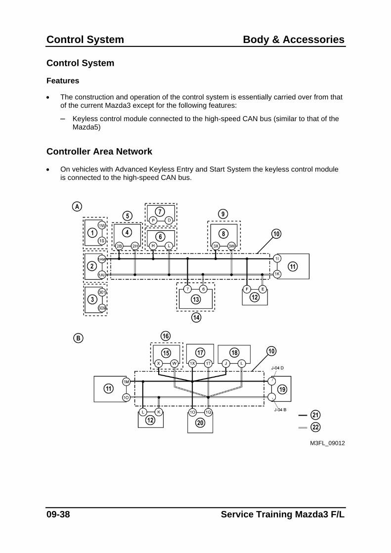
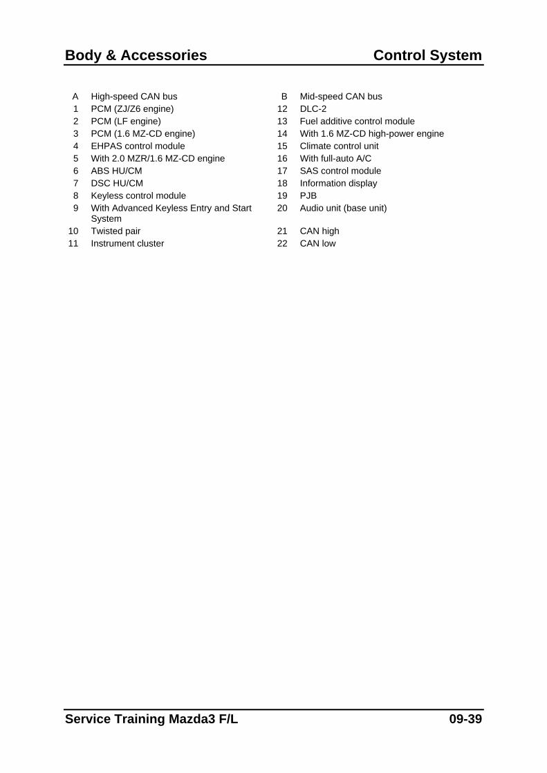
Control System
Features
• The construction and operation of the control system is essentially carried over from that of the current Mazda3 except for the following features:
– Keyless control module connected to the high-speed CAN bus (similar to that of the Mazda5)
Controller Area Network
• On vehicles with Advanced Keyless Entry and Start System the keyless control module is connected to the high-speed CAN bus.
M3FL_09012
09-38 Service Training Mazda3 F/L
Body & Accessories Control System
A High-speed CAN bus B Mid-speed CAN bus 1 PCM (ZJ/Z6 engine) 12 DLC-2 2 PCM (LF engine) 13 Fuel additive control module 3 PCM (1.6 MZ-CD engine) 14 With 1.6 MZ-CD high-power engine 4 EHPAS control module 15 Climate control unit 5 With 2.0 MZR/1.6 MZ-CD engine 16 With full-auto A/C 6 ABS HU/CM 17 SAS control module 7 DSC HU/CM 18 Information display 8 Keyless control module 19 PJB 9 With Advanced Keyless Entry and Start
System 20 Audio unit (base unit)
10 Twisted pair 21 CAN high 11 Instrument cluster 22 CAN low
Service Training Mazda3 F/L 09-39
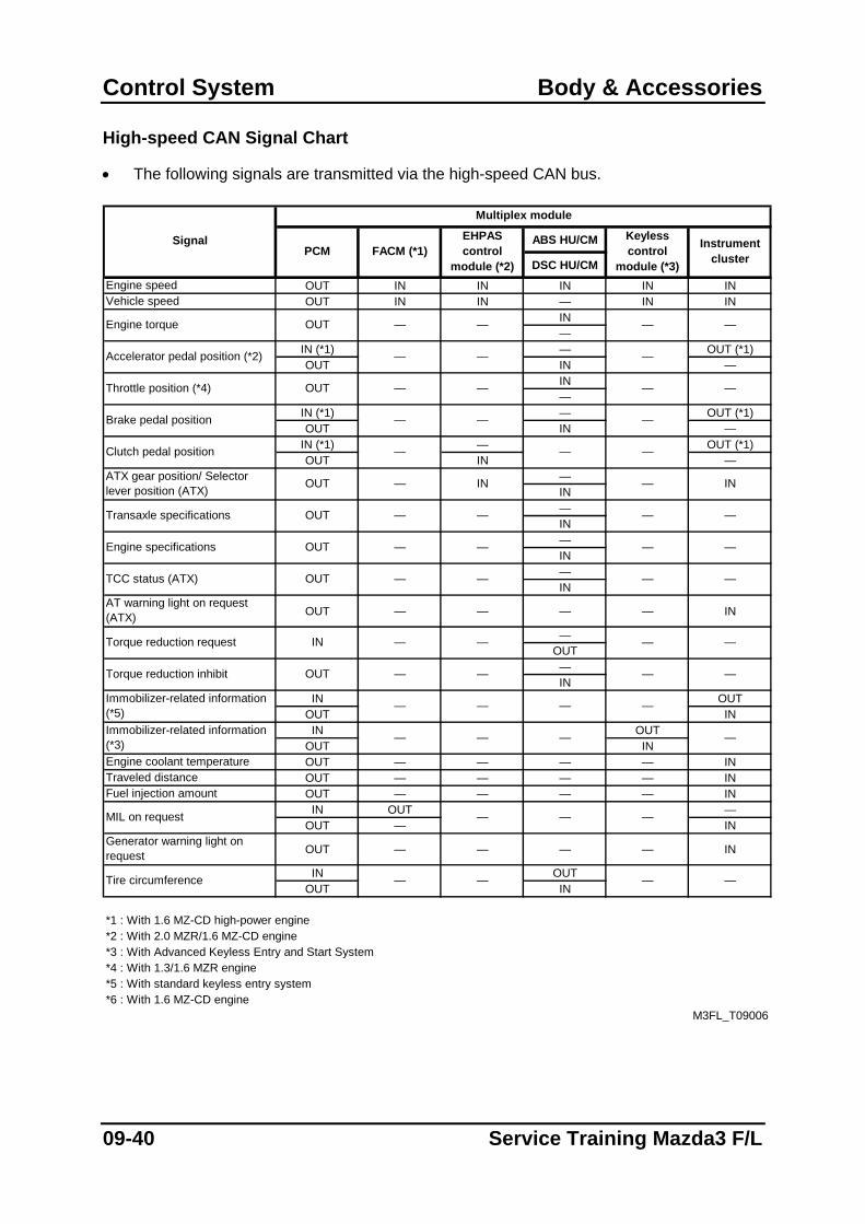
Control System Body & Accessories
High-speed CAN Signal Chart
• The following signals are transmitted via the high-speed CAN bus.
ABS HU/CM
DSC HU/CMEngine speed OUT IN IN IN IN INVehicle speed OUT IN IN — IN IN
IN—
IN (*1) — OUT (*1)OUT IN —
IN—
IN (*1) — OUT (*1)OUT IN —
IN (*1) — OUT (*1)OUT IN —
—IN—IN—IN—IN
AT warning light on request (ATX) OUT — — — — IN
—OUT—IN
IN OUTOUT ININ OUT
OUT INEngine coolant temperature OUT — — — — INTraveled distance OUT — — — — INFuel injection amount OUT — — — — IN
IN OUT —OUT — IN
Generator warning light on request OUT — — — — IN
IN OUTOUT IN
*1 : With 1.6 MZ-CD high-power engine*2 : With 2.0 MZR/1.6 MZ-CD engine*3 : With Advanced Keyless Entry and Start System*4 : With 1.3/1.6 MZR engine*5 : With standard keyless entry system*6 : With 1.6 MZ-CD engine
INOUT
M3FL_T09006
—
Brake pedal position — — —
Accelerator pedal position (*2) — —
—
Tire circumference
—
—
——
—
—
MIL on request
Immobilizer-related information (*3)
—
—
— —
—
— —
—
—
IN
—
—
—
—
—
—
—
—
—
—
Instrument cluster
—
—
Keyless control
module (*3)
—
—
— —
—
Multiplex module
PCM
OUT
EHPAS control
module (*2)FACM (*1)
Immobilizer-related information (*5)
Signal
Engine torque
TCC status (ATX)
Torque reduction request
Torque reduction inhibit
Clutch pedal position
Throttle position (*4)
ATX gear position/ Selector lever position (ATX)
—
—
—
Transaxle specifications
Engine specifications OUT
—
—
—
OUT — —
—
OUT
OUT — —
IN — —
OUT — —
09-40 Service Training Mazda3 F/L
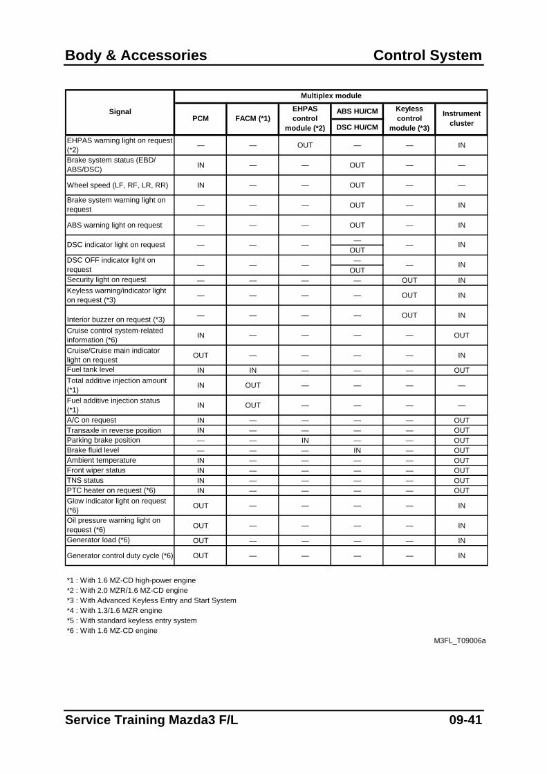
Body & Accessories Control System
ABS HU/CM
DSC HU/CM
EHPAS warning light on request (*2) — — OUT — — IN
Brake system status (EBD/ ABS/DSC) IN — — OUT — —
Wheel speed (LF, RF, LR, RR) IN — — OUT — —
Brake system warning light on request — — — OUT — IN
ABS warning light on request — — — OUT — IN
—OUT—
OUTSecurity light on request — — — — OUT INKeyless warning/indicator light on request (*3) — — — — OUT IN
Interior buzzer on request (*3) — — — — OUT IN
Cruise control system-related information (*6) IN — — — — OUT
Cruise/Cruise main indicator light on request OUT — — — — IN
Fuel tank level IN IN — — — OUTTotal additive injection amount (*1) IN OUT — — — —
Fuel additive injection status (*1) IN OUT — — — —
A/C on request IN — — — — OUTTransaxle in reverse position IN — — — — OUTParking brake position — — IN — — OUTBrake fluid level — — — IN — OUTAmbient temperature IN — — — — OUTFront wiper status IN — — — — OUTTNS status IN — — — — OUTPTC heater on request (*6) IN — — — — OUTGlow indicator light on request (*6) OUT — — — — IN
Oil pressure warning light on request (*6) OUT — — — — IN
Generator load (*6) OUT — — — — IN
Generator control duty cycle (*6) OUT — — — — IN
*1 : With 1.6 MZ-CD high-power engine*2 : With 2.0 MZR/1.6 MZ-CD engine*3 : With Advanced Keyless Entry and Start System*4 : With 1.3/1.6 MZR engine*5 : With standard keyless entry system*6 : With 1.6 MZ-CD engine
— —
Signal
Multiplex module
PCMEHPAS control
module (*2)FACM (*1) Instrument
cluster
Keyless control
module (*3)
M3FL_T09006a
DSC indicator light on request — — — — IN
DSC OFF indicator light on request — — IN
Service Training Mazda3 F/L 09-41
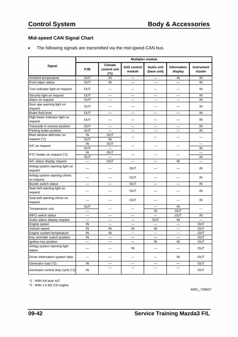
Control System Body & Accessories
Mid-speed CAN Signal Chart
• The following signals are transmitted via the mid-speed-CAN bus.
PJBClimate
control unit (*1)
SAS control module
Audio unit (base unit)
Information display
Instrument cluster
Ambient temperature OUT IN — — IN INFront wiper status OUT IN — — — IN
Turn indicator light on request OUT — — — — IN
Security light on request OUT — — — — INAlarm on request OUT — — — — INDoor ajar warning light on request OUT — — — — IN
Brake fluid level OUT — — — — INHigh-beam indicator light on request OUT — — — — IN
Transaxle in reverse position OUT — — — — INParking brake position OUT — — — — IN
IN OUTOUT ININ OUT —
OUT — ININ OUT —
OUT — INA/C status display request — OUT — — IN —Airbag system warning light on request — — OUT — — IN
Airbag system warning chime on request — — OUT — — IN
Buckle switch status — — OUT — — INSeat belt warning light on request — — OUT — — IN
Seat belt warning chime on request — — OUT — — IN
OUT — IN— IN OUT
INFO switch status — — — — OUT INAudio status display request — — — OUT IN —Engine speed IN — — — — OUTVehicle speed IN IN IN IN — OUTEngine coolant temperature IN IN — — — OUTKey reminder switch position IN — — — — OUTIgnition key position — — — IN IN OUTAirbag system warning light status — — IN — — OUT
Driver information system data — — — — IN OUT
Generator load (*2) IN — — — — OUT
Generator control duty cycle (*2) IN— — — —
OUT
*1 : With full-auto A/C*2 : With 1.6 MZ-CD engine
—Temperature unit —
PTC heater on request (*2) — — —
—
M3FL_T09007
—
Signal
Rear window defroster on request (*1)
A/C on request
Multiplex module
— —
—
—
—
—
09-42 Service Training Mazda3 F/L
Appendix
Mazda3 Product Changes History
• This section describes the product changes introduced during the cost reduction F/L of the Mazda3 in March 2005 (from VIN JMZBK1*****261573 on, except for vehicles with 1.6 MZ-CD high-power engine and DPF that were face-lifted from VIN JMZBK1*Y2**270808 on).
Engine
• Fuel filter with separate fuel warmer replaced by filter with integrated fuel warmer (only vehicles with 1.6 MZ-CD engine).
Steering
• Steering angle sensor integrated in the steering gear replaced by steering angle sensor at the steering wheel (only vehicles with EHPAS).
HVAC
• PTC heater deleted for certain markets (only vehicles with 1.6 MZ-CD engine). Restraints
• Dual-stage driver/passenger airbags replaced by single-stage airbags. Body & Accessories
• Black leather seats and seat warmer added for left-hand drive vehicles (optional).
• Separate key and transmitter replaced by retractable key with integrated transmitter.
• Body-coloured outer door handles, side mouldings and outer mirrors replaced by black-coloured components (only for Base grade).
• Rear ash tray, subtrunk box and trunk hooks deleted (the latter two only on 5HB vehicles).
• Door trim material modified.
• Red-coloured rear combination lamp bezel replaced by black-coloured bezel (except for Sports grade).
Service Training Mazda3 F/L
Appendix
• Audio unit (base unit) with separate upper module replaced by audio unit (base unit) with integrated upper module.
• Audio unit without CD player replaced by audio unit with CD player (except for Base grade).
• Bose audio system with CD changer, audio amplifier and woofer added (optional).
• Navigation system without TMC replaced by navigation system with TMC.
• Information display connected to the audio unit replaced by information display connected to the mid-speed CAN bus.
• Exterior colour Carbon Grey (28B) added.
Service Training Mazda3 F/L
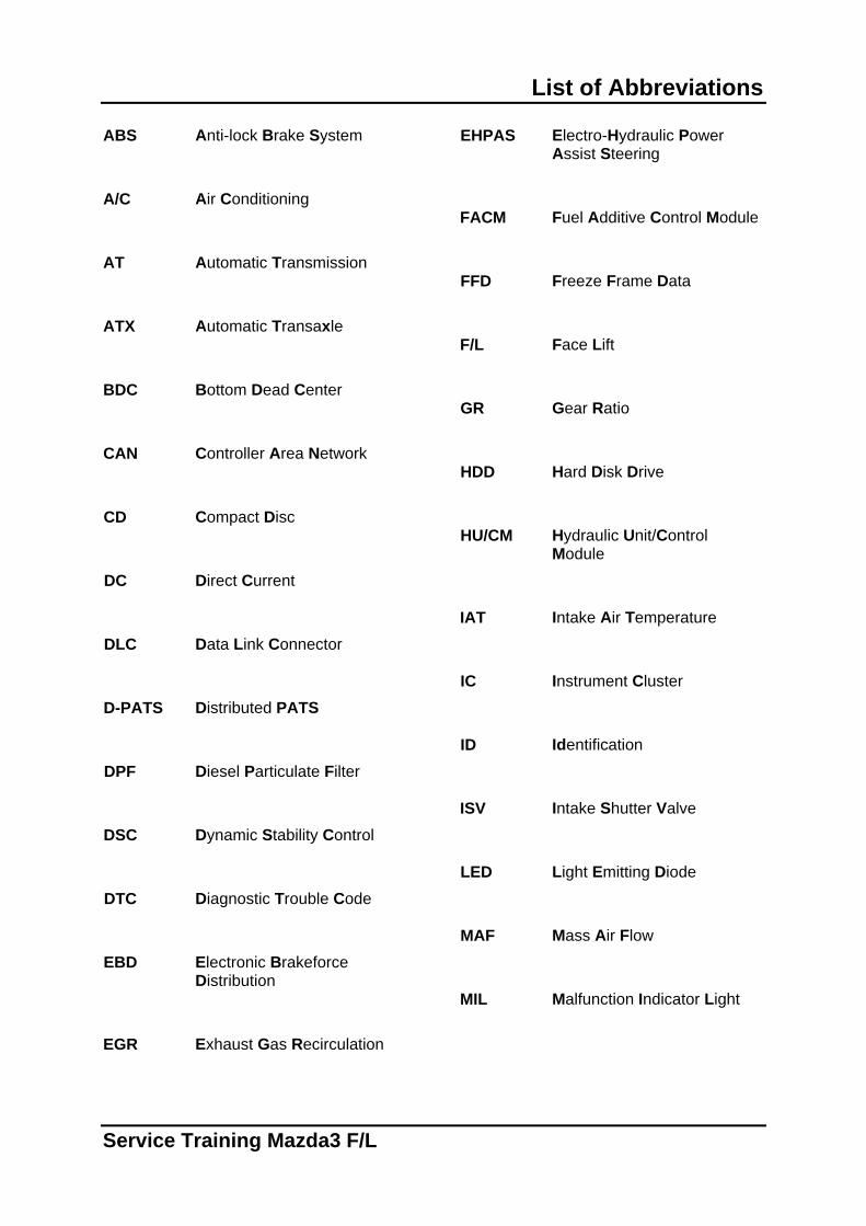
List of Abbreviations
ABS Anti-lock Brake System A/C Air Conditioning AT Automatic Transmission ATX Automatic Transaxle BDC Bottom Dead Center CAN Controller Area Network CD Compact Disc DC Direct Current DLC Data Link Connector D-PATS Distributed PATS DPF Diesel Particulate Filter DSC Dynamic Stability Control DTC Diagnostic Trouble Code EBD Electronic Brakeforce
Distribution EGR Exhaust Gas Recirculation
EHPAS Electro-Hydraulic Power Assist Steering
FACM Fuel Additive Control Module FFD Freeze Frame Data F/L Face Lift GR Gear Ratio HDD Hard Disk Drive HU/CM Hydraulic Unit/Control
Module IAT Intake Air Temperature IC Instrument Cluster ID Identification ISV Intake Shutter Valve LED Light Emitting Diode MAF Mass Air Flow MIL Malfunction Indicator Light
Service Training Mazda3 F/L
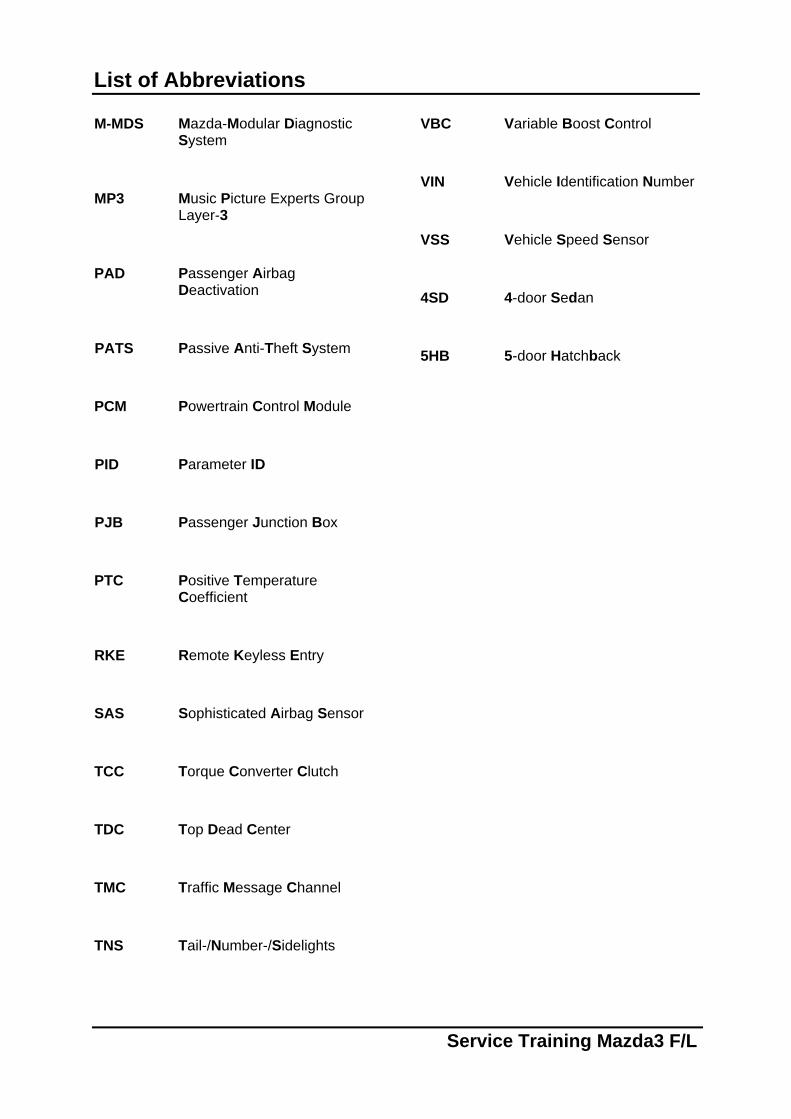
List of Abbreviations
M-MDS Mazda-Modular Diagnostic System
MP3 Music Picture Experts Group
Layer-3 PAD Passenger Airbag
Deactivation PATS Passive Anti-Theft System PCM Powertrain Control Module PID Parameter ID PJB Passenger Junction Box PTC Positive Temperature
Coefficient RKE Remote Keyless Entry SAS Sophisticated Airbag Sensor TCC Torque Converter Clutch TDC Top Dead Center TMC Traffic Message Channel TNS Tail-/Number-/Sidelights
VBC Variable Boost Control VIN Vehicle Identification Number VSS Vehicle Speed Sensor 4SD 4-door Sedan 5HB 5-door Hatchback
Service Training Mazda3 F/L


