4.6.4 Attach Rear Top Section ....................................................................................... 25
4.6.5 Attach Front Section .............................................................................................. 26
ANNEX A - SYSTEM SPECIFICATIONS ................................................................................... 28
ANNEX B - PHYSICAL DIMENSIONS ....................................................................................... 29
ANNEX C - CABLE CONNECTORS .......................................................................................... 34
ANNEX D - COMMON ACRONYMS USED IN THIS MANUAL .................................................. 36
ANNEX E - SPARE PARTS & PART NUMBERS ....................................................................... 37
MB1 User Manual
Page 5 of 37 07/16/13
1 INTRODUCTION The MB1 multibeam echo sounder is a portable, easy to use bathymetric system that is designed to collect swath bathymetry using acoustic means. Developed by the Teledyne Marine Group of companies, it has been designed with the surveyor in mind to be simple to use yet provide full functionality. To make learning about the features of MB1 easy to follow, this document is structured as a step-by-step manual. The first manual (this manual) covers the MB1 as a product, it provides instructions on how to install the hardware, how cables are wired to their connectors and some simple troubleshooting tips. The second manual details the control software and how the system can be used operationally. Both manuals should be used together to learn how to use the system. It is recommended that before the system is operated for the first time, the user should familiarize themselves with the contents of this manual in order to ensure optimal use of the system.
1.1 Warnings and Cautions Throughout this manual there are several points that may either result in damage and/or loss of the system (Warnings) and other points that may result in improper use of the system (Cautions). These are annotated using the following format. Warning: (Example) Applying DC electrical power greater than 30 Volts to the RTA
may result in damage to the unit. Caution: (Example) Ensure that the cable of the unit is facing aft (toward the rear
of the vessel) during normal operation.
MB1 User Manual
Page 6 of 37 07/16/13
2 PRODUCT DESCRIPTION
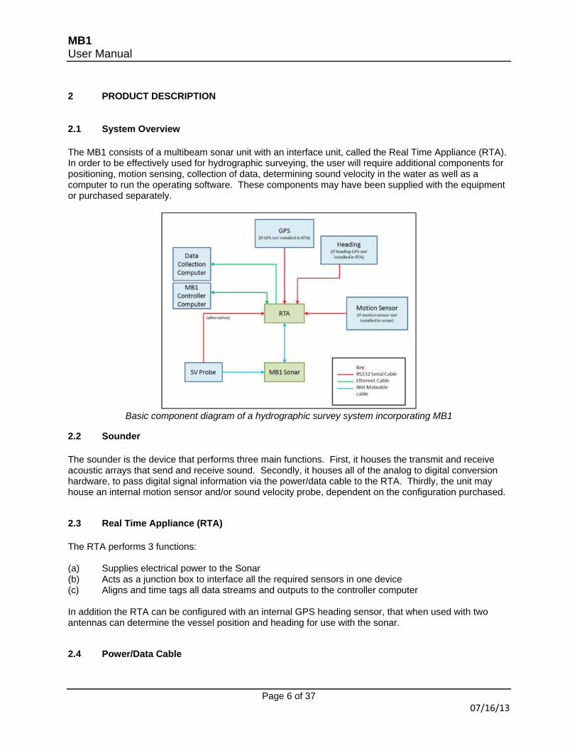
2.1 System Overview The MB1 consists of a multibeam sonar unit with an interface unit, called the Real Time Appliance (RTA). In order to be effectively used for hydrographic surveying, the user will require additional components for positioning, motion sensing, collection of data, determining sound velocity in the water as well as a computer to run the operating software. These components may have been supplied with the equipment or purchased separately.
Basic component diagram of a hydrographic survey system incorporating MB1
2.2 Sounder The sounder is the device that performs three main functions. First, it houses the transmit and receive acoustic arrays that send and receive sound. Secondly, it houses all of the analog to digital conversion hardware, to pass digital signal information via the power/data cable to the RTA. Thirdly, the unit may house an internal motion sensor and/or sound velocity probe, dependent on the configuration purchased.
2.3 Real Time Appliance (RTA) The RTA performs 3 functions: (a) Supplies electrical power to the Sonar (b) Acts as a junction box to interface all the required sensors in one device (c) Aligns and time tags all data streams and outputs to the controller computer In addition the RTA can be configured with an internal GPS heading sensor, that when used with two antennas can determine the vessel position and heading for use with the sonar.
2.4 Power/Data Cable
MB1 User Manual
Page 7 of 37 7/6/12
This is a specially constructed cable for MB1, terminated at the wet end (sonar end) with an Impulse Titan series connector, and at the RTA end with an Amphenol connector. Replacement part number 2313-0100-0000.
2.5 Mounting Plate This prefabricated stainless steel plate can be used as a generic mounting arrangement for most over the side mounts.
2.6 Digibar V (optional) The Digibar V is an instrument that determines sound velocity at a fixed point. This sound velocity is used by the MB1 software in calculating the receive beams of the multibeam, and is required for correct use of the system. A different real time sound velocity probe may be used and interfaced to the RTA using the SVP port, providing the AML sentence can be output.
MB1 with optional Digibar V sound velocity probe attached
2.7 Power Supply This is a recommended 100-240V A/C power supply with an output of 24V at 100W. This may be used to power the sounder through the RTA. Alternatively a DC power cable can be supplied (Part number: CABLEPOWDC) by Odom when required.
2.8 Possible Configurations of the MB1 The MB1 can be used as a standalone sonar as part of a pre existing suite of other sensors (Motion, Heading, Position etc.) or has configurable options. The options that may be added to the system are an internal GPS & Heading board (Hemisphere H320 model), TSS DMS525 motion sensor and the Digibar V real time sound velocity probe. Any of these inputs can be configured to either be external (input to either the RTA or sonar head) or internal as fitted to the equipment. The table below shows the possible configurations.
* Note: At the time of writing the internal motion sensor cannot be rotated past 10 degrees of roll. External motion sensor will be required in this case.
MB1 User Manual
Page 9 of 37 07/16/13
3 COMPONENTS
3.1 Sounder
The sounder consists of a Titanium lower portion, housing the acoustic transmit and receive arrays. The upper portion houses the internal electronics and is manufactured from Acetal, a tough and corrosion resistant plastic. The two connectors shown above are used for a connection to a real time sound velocity probe, the Odom Digibar V, and the other is a power/data interface for the unit. On the top of the unit are 4 bronze mounting rods that are threaded to accept 8 mounting bolts through the top of the unit.
MB1 User Manual
Page 10 of 37 7/6/12
Turning the unit over, the transmit array (the larger black square) and the receive array (the smaller black square) can be clearly seen. A carrying handle is located at one end of the base of the unit, and may also be used as a tie off point to prevent loss in the event that the sonar mount was to break.
3.1.1 Optional Internal Motion Sensor If the unit has been supplied with an internal motion sensor, this can be used instead of an external sensor to correct for vessel motion. The advantage of the internal sensor is reduced set up time (the cabling is already in place and offsets do not need to be measured between the sonar and the motion sensor) and also in vessels with temporary mounts the mount flex will be measured by the motion sensor.
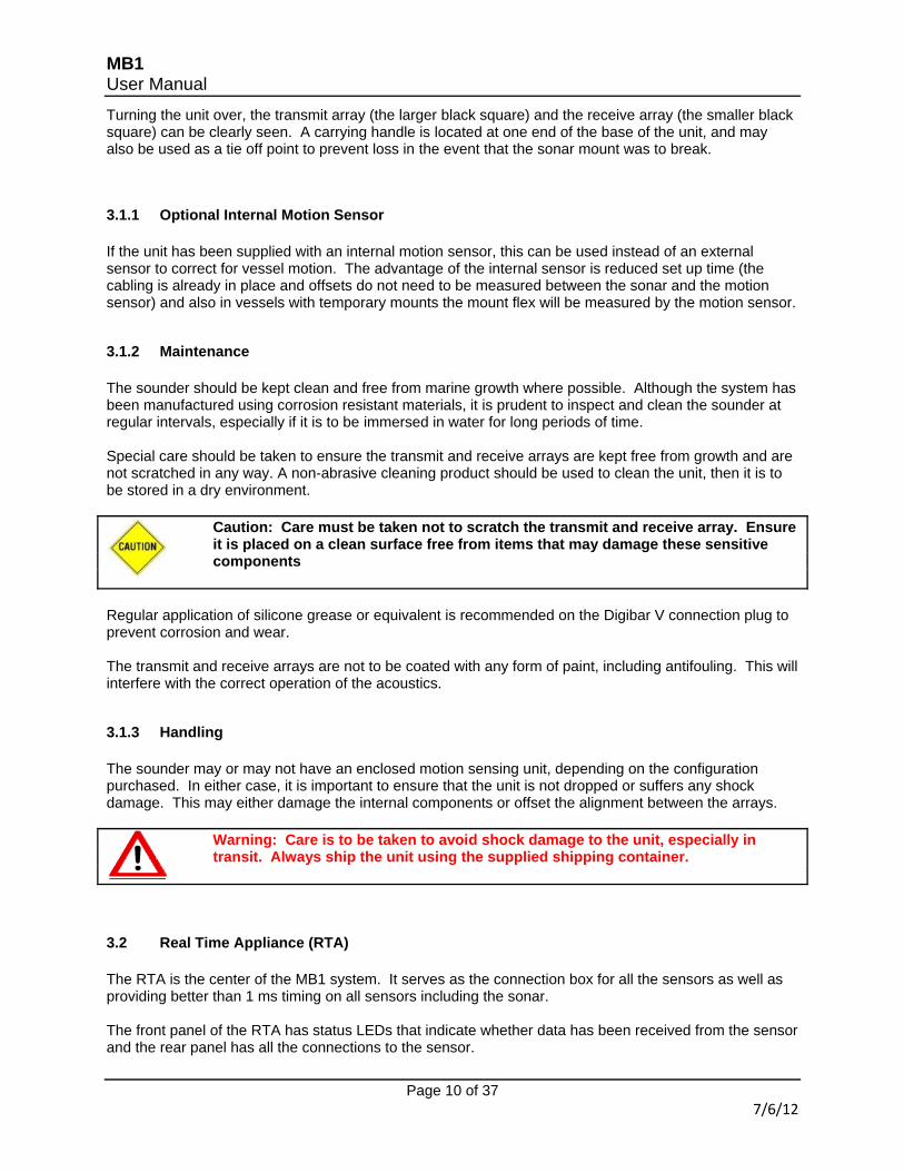
3.1.2 Maintenance The sounder should be kept clean and free from marine growth where possible. Although the system has been manufactured using corrosion resistant materials, it is prudent to inspect and clean the sounder at regular intervals, especially if it is to be immersed in water for long periods of time. Special care should be taken to ensure the transmit and receive arrays are kept free from growth and are not scratched in any way. A non-abrasive cleaning product should be used to clean the unit, then it is to be stored in a dry environment. Caution: Care must be taken not to scratch the transmit and receive array. Ensure
it is placed on a clean surface free from items that may damage these sensitive components
Regular application of silicone grease or equivalent is recommended on the Digibar V connection plug to prevent corrosion and wear. The transmit and receive arrays are not to be coated with any form of paint, including antifouling. This will interfere with the correct operation of the acoustics.
3.1.3 Handling The sounder may or may not have an enclosed motion sensing unit, depending on the configuration purchased. In either case, it is important to ensure that the unit is not dropped or suffers any shock damage. This may either damage the internal components or offset the alignment between the arrays. Warning: Care is to be taken to avoid shock damage to the unit, especially in
transit. Always ship the unit using the supplied shipping container.
3.2 Real Time Appliance (RTA) The RTA is the center of the MB1 system. It serves as the connection box for all the sensors as well as providing better than 1 ms timing on all sensors including the sonar. The front panel of the RTA has status LEDs that indicate whether data has been received from the sensor and the rear panel has all the connections to the sensor.
MB1 User Manual
Page 11 of 37 7/6/12
When setting up the MB1, the RTA should be placed on a non-insulating surface wherever possible to encourage heat to dissipate from the base plate. This is especially important in hot environments or where the unit is exposed to sunlight.
3.2.1 Front Panel
The front panel of the RTA consists of a series of status indicating LEDs, which tell the user when data is being received to the RTA from each sensor. The RTA and sonar are also powered by depressing the circular power button to the right of the front panel. Before the RTA will indicate the correct sequencing of lights, each sensor must be attached and configured in section 3.2.2 of this manual. Once the power button is depressed, the lights will perform the following self check sequence: (a) All lights in the IO box will flash once. (b) The Link lights for both Sonar 1 and 2 will flash once. (c) After 10 seconds, the Link lights for both Sonar 1 and 2 will flash once again. (d) After 35 seconds, the link light for the sonar will begin to flash, and the system is ready for use. Caution: The system is ready for use only when the Link light is flashing During normal operation the status lights will flash in the following manner: Indicator LED
Frequency
(Hz) Notes
I/O Data Links ZDA 1 Hz 1PPS 100ms pulse every 1 second GPS At rate of GPS input, 1-5 Hz SVP At rate of SVP input, 1-5 Hz
MB1 User Manual
Page 12 of 37 7/6/12
HPR At rate of HPR input, 40 Hz May appear to be constantly on due to high data rate Heading At rate of heading input, 5Hz Spare N/A TSPU Various When communicating with TSPU Sonar 1 Data Various When communicating with Sonar Ping As per ping rate of sonar Depth and computer processor speed dependent Link Continuous When sonar is connected Sonar 2 Data Various When communicating with Sonar Ping As per ping rate of sonar Depth and computer processor speed dependent Link Continuous When sonar is connected
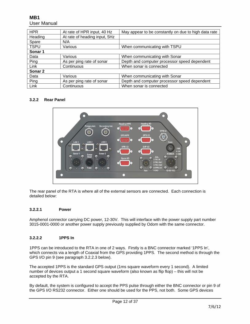
3.2.2 Rear Panel
The rear panel of the RTA is where all of the external sensors are connected. Each connection is detailed below:
3.2.2.1 Power Amphenol connector carrying DC power, 12-30V. This will interface with the power supply part number 3015-0001-0000 or another power supply previously supplied by Odom with the same connector.
3.2.2.2 1PPS In 1PPS can be introduced to the RTA in one of 2 ways. Firstly is a BNC connector marked ‘1PPS In’, which connects via a length of Coaxial from the GPS providing 1PPS. The second method is through the GPS I/O pin 9 (see paragraph 3.2.2.3 below). The accepted 1PPS is the standard GPS output (1ms square waveform every 1 second). A limited number of devices output a 1 second square waveform (also known as flip flop) – this will not be accepted by the RTA. By default, the system is configured to accept the PPS pulse through either the BNC connector or pin 9 of the GPS I/O RS232 connector. Either one should be used for the PPS, not both. Some GPS devices
MB1 User Manual
Page 13 of 37 7/6/12
such as the C-Nav 2050 & 3050, however, output other signals on pin 9 of their RS232 that may interfere with the timing of the RTA when the BNC is used for the PPS signal. This will be seen as a timing error within the Image control software, along with the PPS LED blinking at rates other than once per second. If this occurs, pin 9 of the GPS I/O RS232 can be disabled in one of two ways: (a) A null modem with pin 9 disabled can be used to interface between the GPS and the GPS I/O on the RTA. (b) The PPS can be set within the RTA itself, inside of the unit on the back panel. To change the PPS input method from the default (BNC and Pin9) to BNC or Pin8 or Pin9 perform the following procedure: (i) Disconnect the power cable. With the rear of the RTA facing you, remove all of the connector plugs.
(ii) Using a 3mm allen key, remove the 7 bolts that hold the rear panel to the casing of the RTA. Carefully pull the rear panel away from the casing, ensuring that the cables are not put under tension.
MB1 User Manual
Page 14 of 37 7/6/12
(iii) Mounted to the rear panel is the interface board to the serial connectors. This has 4 small jumper connections, two of which will determine whether pin 9 and pin 8 can be used to accept the PPS signal. There are also two disconnected jumpers at the top of the board - do not change these.
(iv) The small black connector bridges the two pins when connected, and sits on only one of the pins when disconnected. Below we can see the default, pin 8 (JP4) is disconnected on the right and pin 9 (JP3) is connected on the left.
(v) To disable pin 9, remove the jumper connector from both pins and reattach to a single pin. (vi) (If required) to enable pin 8, remove the jumper connector from the single pin and attach to both pins. (vii) Re-align the rear panel with the RTA housing, ensuring that the O-ring seal is correctly seated in the groove on the rear panel. Insert the 7 bolts into the rear panel and tighten with the allen key.
3.2.2.3 GPS I/O
MB1 User Manual
Page 15 of 37 7/6/12
This RS232 connector is used to interface the positioning device into the RTA. The 3 messages to be used are NMEA ZDA, GGA and VTG at rates of 1-5 Hz. The formats of the standard NMEA sentences are as follows:
GGA $GPGGA,hhmmss.ss,llll.ll,a,yyyyy.yy,a,x,xx,x.x,x.x,M,x.x,M,x.x,xxxx*hh 1 Header 2 Time in UTC (hours, minutes, seconds and decimal seconds) 3 Latitude 4 N or S 5 Longitude 6 E or W 7 GPS quality indicator (0=invalid; 1=GPS fix; 2=Diff. GPS fix) 8 Number of satellites used for fix 9 HDOP 10 Antenna Altitude above Geoid 11 Antenna Height unit 12 Geoidal separation 13 Geoidal separation unit 14 Age in seconds since last update from differential reference station 15 Differential reference station identification number 16 Checksum
ZDA $GPZDA,hhmmss.ss,dd,mm,yyyy,xx,xx 1 Header 2 Time in UTC (hours, minutes, seconds and decimal seconds) 3 Day of the Month 4 Month of the Year 5 Year 6 Local Time Zone (Hours) 7 Local Time Zone (Minutes)
VTG $GPVTG,t,T,,,s.ss,N,s.ss,K*hh 1 Header 2 Track made good 3 Fixed 'T' means track is relative to true north 4 Not used 5 Not used 6 Speed over ground in Knots 7 Fixed 'N' means speed over ground is in Knots 8 Speed over ground in KM/H 9 Fixed 'K' means speed over ground is in KM/H 10 Checksum
PPS may also be input to the RTA via pin 9 of this connector (default setting) or by pin 8 of the connector. To use pin 8, see the instructions in paragraph 3.2.2.2 to enable this feature. The GPS I/O port is also used to interface with an internal H320 GPS board (if fitted).
MB1 User Manual
Page 16 of 37 7/6/12
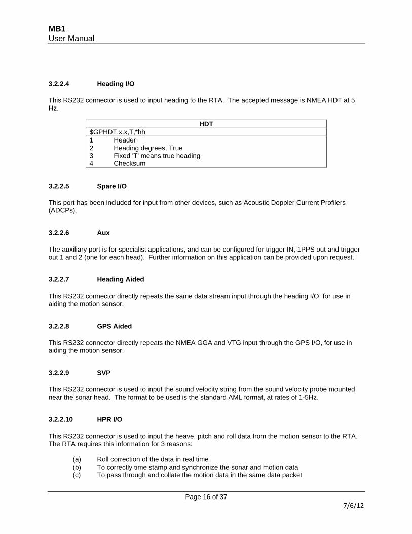
3.2.2.4 Heading I/O This RS232 connector is used to input heading to the RTA. The accepted message is NMEA HDT at 5 Hz.
3.2.2.5 Spare I/O This port has been included for input from other devices, such as Acoustic Doppler Current Profilers (ADCPs).
3.2.2.6 Aux The auxiliary port is for specialist applications, and can be configured for trigger IN, 1PPS out and trigger out 1 and 2 (one for each head). Further information on this application can be provided upon request.
3.2.2.7 Heading Aided This RS232 connector directly repeats the same data stream input through the heading I/O, for use in aiding the motion sensor.
3.2.2.8 GPS Aided This RS232 connector directly repeats the NMEA GGA and VTG input through the GPS I/O, for use in aiding the motion sensor.
3.2.2.9 SVP This RS232 connector is used to input the sound velocity string from the sound velocity probe mounted near the sonar head. The format to be used is the standard AML format, at rates of 1-5Hz.
3.2.2.10 HPR I/O This RS232 connector is used to input the heave, pitch and roll data from the motion sensor to the RTA. The RTA requires this information for 3 reasons: (a) Roll correction of the data in real time (b) To correctly time stamp and synchronize the sonar and motion data (c) To pass through and collate the motion data in the same data packet
MB1 User Manual
Page 17 of 37 7/6/12
The data input must be the TSS1 data string format, at data rates of up to 40Hz.
3.2.2.11 Ant 1 / Ant 2 (Optional) These TNC connectors are used to interface the heading and positioning antennas with the optional internal GPS. Caution: Ensure when connecting the antennas that the primary antenna is
mounted in accordance with the primary location in the GPS settings – failure to do so will result in an inversed heading (+180 degrees)
For more information see section 3.2.3.
3.2.2.12 TSPU PC This Ethernet connector interfaces with the computer that is to run the MB1 controller software. One end of the supplied Category 5e cable should be inserted into this connector, and the other end into the computer dedicated to operating the MB1 software.
3.2.2.13 Data Acq PC This Ethernet connector interfaces with the computer that is to gather the data output, typically this computer would be running software such as EIVA, Hypack or QPS. One end of the supplied Category 5e cable should be inserted into this connector, and the other end into the computer dedicated to operating the acquisition software.
3.2.2.14 Spare PC This is a spare Ethernet port, interfaced to the internal switch.
3.2.2.15 Sonar 1 This Amphenol connector is used to connect the sonar head to the RTA. If a single head configuration is used, insert the connector on the power/data cable from the sounder to this connector.
3.2.2.16 Sonar Head Fuse The Sonar head fuse is located in the rear of the RTA. It is a 5 x 20mm 5A, 250V fuse, part number 2010-0003-0000.
3.2.2.17 Power Fuse The Power fuse is located in the rear of the RTA. It is a 5 x 20mm 5A, 250V fuse, part number 2010-0003-0000.
3.2.2.18 Sonar 2
MB1 User Manual
Page 18 of 37 7/6/12
This Amphenol connector is used to connect the sonar head to the RTA. If a dual head configuration is used, insert the plug on the power/data cable from the second sounder to this connector.
3.2.3 Optional Internal GPS Heading The system may be configured with an internal Hemisphere H320 GPS & Heading board. If this is included, it may be used to provide the GPS, timing and heading sentences required by the RTA. To configure the internal GPS, first connect the 2 supplied antennas to the antenna connectors on the rear of the RTA. Then connect to the GPS by using a serial cable from a PC to the 'GPS I/O' port on the rear of the RTA. Finally connect to the GPS using the Hemisphere software 'PocketMax' or 'VectorPC'. More information on using these softwares, along with download locations, can be found on the Hemisphere website at http://www.hemispheregps.com/. When configuring the internal GPS to interface directly to the RTA, set the following ports:
NMEA Message Port GGA / ZDA / VTG A
HDT B Once these have been set, ensure to note the baud rates used and enter into the Image software as detailed in the MB1 software manual.
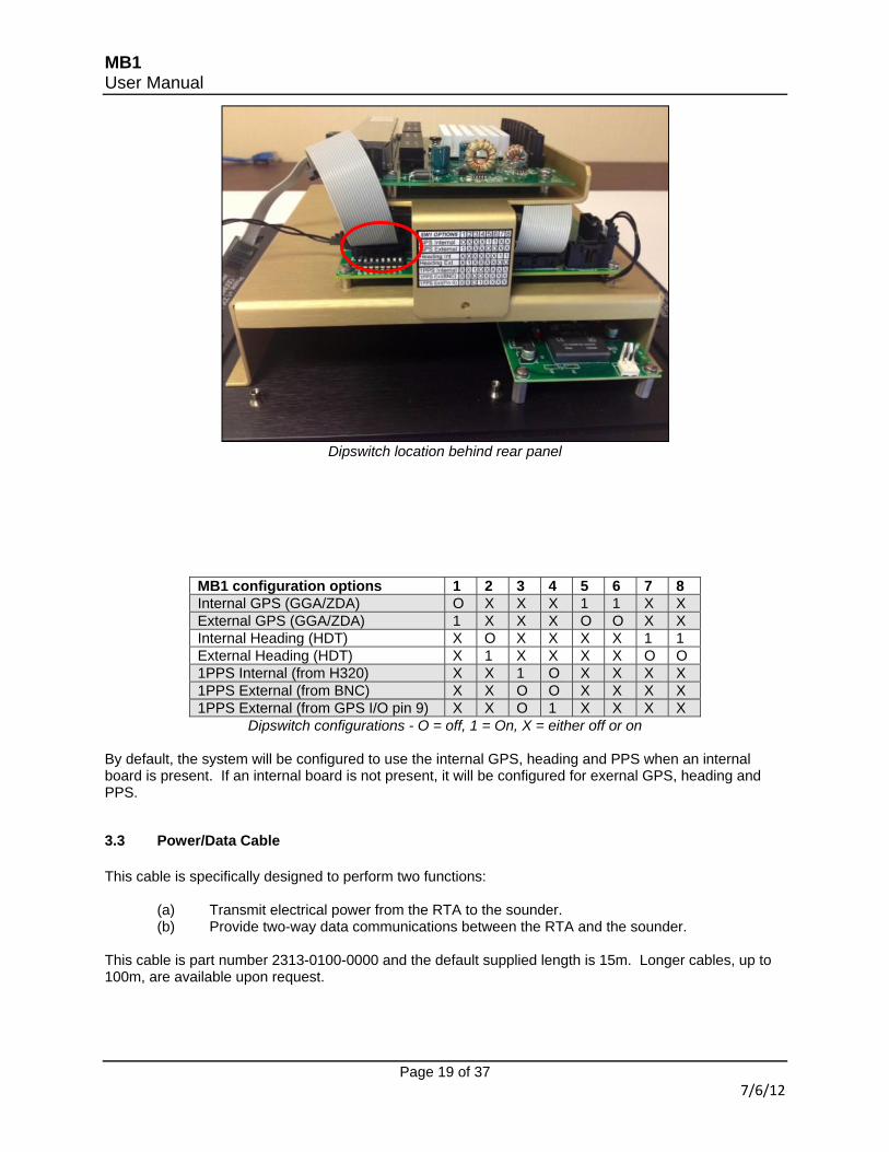
3.2.4 Configuring the RTA Hardware to Operate With Internal/External GPS The RTA has an internal dipswitch that allows the unit to be used in a variety of modes. For example, with an internal GPS, with internal motion and external GPS, external motion and internal GPS etc. These switches can be accessed by removing the rear panel of the RTA (follow the steps outlined in paragraph 3.2.2.2). With the rear panel removed, use a small pick or screwdriver to switch each of the 8 dipswitches to the configuration required. The 'On' position is when the switch is toward the front of the RTA, away from the user. An aide-memoir is also attached to the panel next to the switch.
MB1 User Manual
Page 19 of 37 7/6/12
Dipswitch location behind rear panel
MB1 configuration options 1 2 3 4 5 6 7 8 Internal GPS (GGA/ZDA) O X X X 1 1 X X External GPS (GGA/ZDA) 1 X X X O O X X Internal Heading (HDT) X O X X X X 1 1 External Heading (HDT) X 1 X X X X O O 1PPS Internal (from H320) X X 1 O X X X X 1PPS External (from BNC) X X O O X X X X 1PPS External (from GPS I/O pin 9) X X O 1 X X X X
Dipswitch configurations - O = off, 1 = On, X = either off or on
By default, the system will be configured to use the internal GPS, heading and PPS when an internal board is present. If an internal board is not present, it will be configured for exernal GPS, heading and PPS.
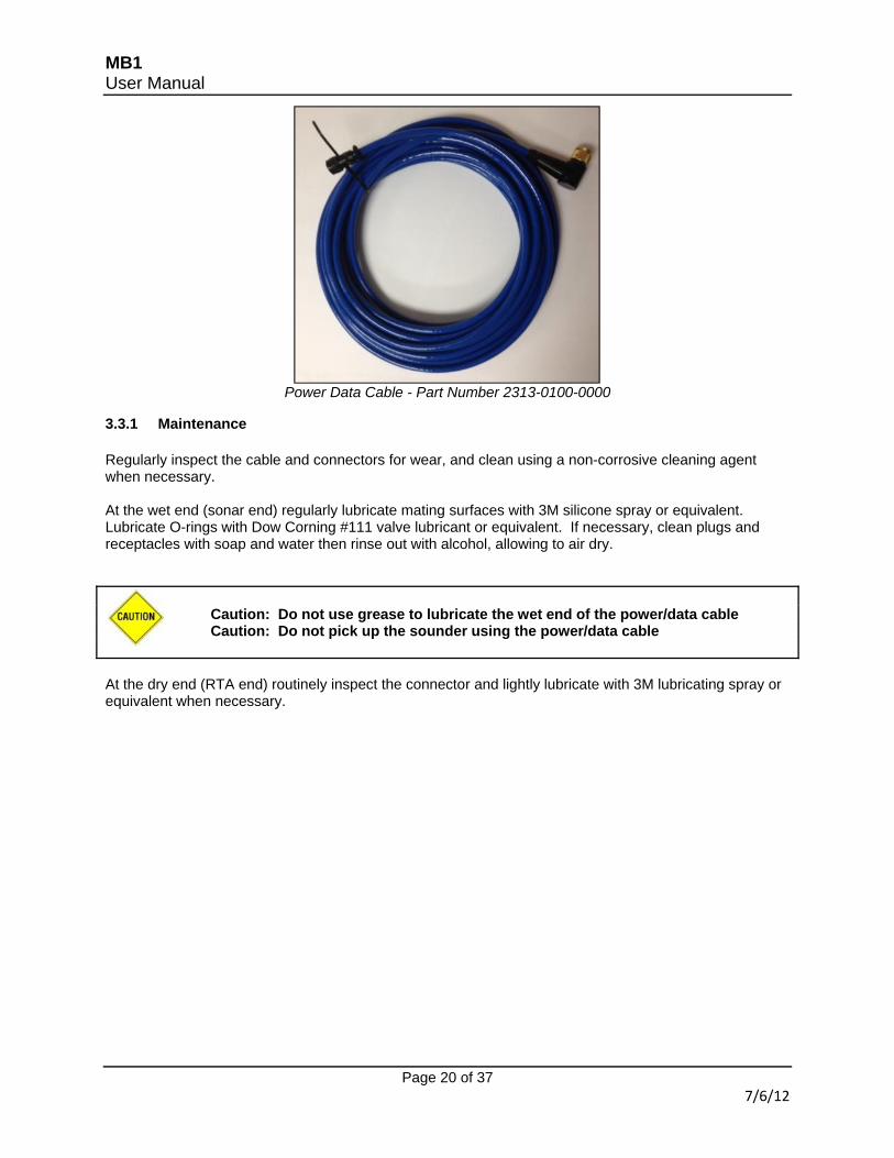
3.3 Power/Data Cable This cable is specifically designed to perform two functions: (a) Transmit electrical power from the RTA to the sounder. (b) Provide two-way data communications between the RTA and the sounder. This cable is part number 2313-0100-0000 and the default supplied length is 15m. Longer cables, up to 100m, are available upon request.
MB1 User Manual
Page 20 of 37 7/6/12
Power Data Cable - Part Number 2313-0100-0000
3.3.1 Maintenance Regularly inspect the cable and connectors for wear, and clean using a non-corrosive cleaning agent when necessary. At the wet end (sonar end) regularly lubricate mating surfaces with 3M silicone spray or equivalent. Lubricate O-rings with Dow Corning #111 valve lubricant or equivalent. If necessary, clean plugs and receptacles with soap and water then rinse out with alcohol, allowing to air dry. Caution: Do not use grease to lubricate the wet end of the power/data cable Caution: Do not pick up the sounder using the power/data cable At the dry end (RTA end) routinely inspect the connector and lightly lubricate with 3M lubricating spray or equivalent when necessary.
MB1 User Manual
Page 21 of 37 07/16/13
4 INSTALLATION
4.1 Mounting the Sonar There are three main methods of mounting the sonar: (a Using M6X1.0 threaded holes in the top of the sonar housing (b) Using M6X1.0 threaded holes on the sides of the base of the sonar housing (c) Using an optional universal mounting plate Most commonly the unit is mounted over the side of the vessel, using a suitable pole and flange arrangement. It is important in this case to avoid any movement in the sonar in relation to the other sensors such as the motion reference unit (if it is not internal to the sonar) and the positioning system. Caution: Ensure that the cable of the unit is facing aft (toward the rear of the
vessel) during normal operation.
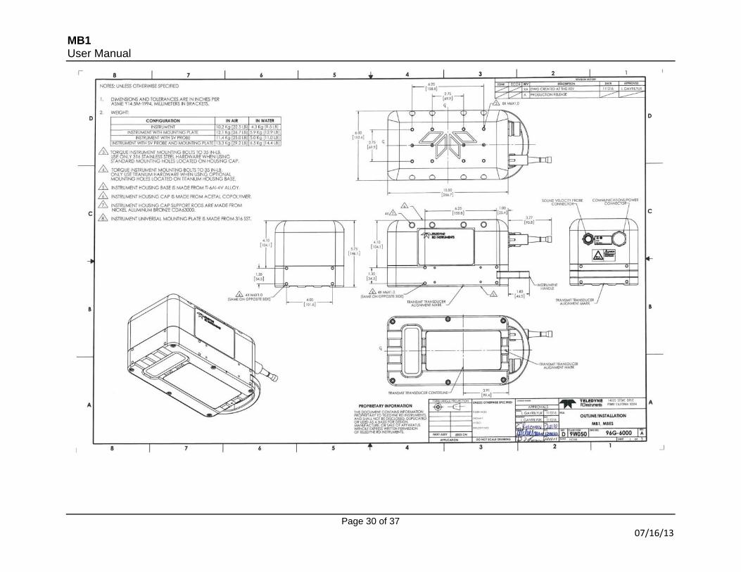
4.1.1 Mounting the Sonar Using Threaded Holes in the Top of the Housing The sonar is supplied with a mounting arrangement consisting of 4 threaded nickel aluminum bronze rods that run through the top of the Acetal copolymer cap. These are threaded for M6X1.0 bolts. Hole pattern is shown on the outline/installation drawing. To mount the sonar, first pre-drill holes in a suitable flange attached to the mounting pole. Then thread the bolts through the flange, into the threaded holes in the sonar head. For a more secure fit, locking washers or threadlocker may be used. Only use 316 stainless steel bolts in this mounting configuration. Using bolts made from different material may lead to corrosion and loss of instrument. Care is to be taken to avoid over-tightening the bolts into these rods, torque bolts to 35 in-lb. Care should also be taken to use bolts that are the correct length for the mounting plate thickness and the thickness of the rods – the bolts should not penetrate through the rods into the Acetal. Try to pick a bolt that will penetrate 0.5in into the sonar housing – this will ensure best possible thread engagement without bottoming out the bolt in the hole. Note: if the threaded hole in one of the bronze mounting rods is stripped, this rod could be replaced by removing the M3X0.5 screw holding the rod to the plastic housing cap and sliding it out of the housing cap. New rod is installed in reverse order, use Loctite 222 threadlocker on the M3X0.5 screw and torque it to 4 in-lb. Caution: Ensure the correct length of bolts are used when mounting directly to the
housing - over tightening longer bolts may cause damage to the housing resulting in the flooding of the unit
4.1.2 Mounting the Sonar Using Threaded Holes in the Base of the Housing Titanium base of the sonar has 4 threaded M6X1.0 holes on each side. Hole pattern is shown on the outline/installation drawing. Only use titanium bolts in this mounting configuration. Using bolts made from different material may lead to corrosion and loss of instrument. Care is to be taken to avoid over-tightening the bolts, torque bolts to 35 in-lb.
MB1 User Manual
Page 22 of 37 7/6/12
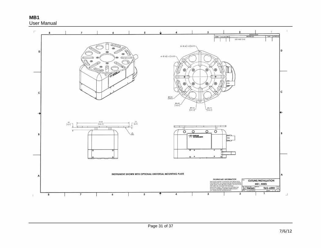
4.1.3 Mounting the Sonar Using Universal Mounting Plate (optional) This quarter inch thick 316 stainless steel plate has been designed to accept a wide range of mounting flanges. It is supplied with an Acetal spacer that is designed to allow space for the heads of the bolts attaching the plate to the mount. It is also supplied with 8 M6X1.0X30mm flat head 316 stainless steel bolts used to secure it to the instrument. Please, see outline/installation drawing for proper installation. Use blue (non-permanent type) threadlocker and torque these bolts to 35 in-lb. A series of 0.56in wide slots on the plate can accept bolts that attach to the mount. Use only 316 stainless steel hardware and mounting flange to avoid corrosion between dissimilar metals. Universal mounting plate also has 4 large holes that could be used as a tie-off point for a safety line.
4.2 Mounting the Digibar V (Optional) Warning: Only Digibar V units serial number 4632 or later can be used to interface
with the sonar head. Earlier units have a different power requirement and interfacing with these may cause damage to the sonar head and/or Digibar V. Acceptable models can be identified by either black standoffs or an MB1 logo on the reflector.
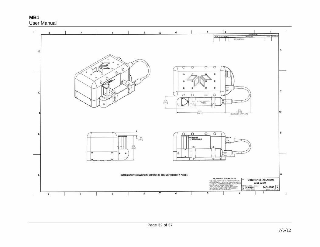
When purchased with the MB1, the Teledyne Odom Digibar V comes with mounting hardware to attach the unit to the side of the MB1 sonar head.
Mounting hardware for the Digibar V
To mount the Digibar V, first attach the spacers to the required side of the sonar head using the 10mm flat head screws. Ensure the larger hole on the spacer is aligned with the hole on the titanium base and the smaller hole with the delrin top of the sonar. Slide the two U shaped clamps over the Digibar V housing. Then place the Digibar V alongside the spacers and using the 35mm screws attach the top of the clamps to the spacers. Using the 40mm screws attach the bottom of the clamps to the base of the sonar, threading through the spacers.
MB1 User Manual
Page 23 of 37 7/6/12
Finally apply a light coating of silicone grease on the male ends of the Digibar cable and the connector on the sonar, then connect the Digibar to the sonar using the short connector cable. Screw down the connector collars finger tight.
4.3 Connecting the Sensors The various cables to the RTA can be connected in any order, although the power to the RTA should only be turned on when all the sensors are connected. When each external sensor is configured (GPS, motion sensor etc.) the data format should be noted. At a minimum this should be the type of data and the baud rate output from the sensor.
4.4 Powering Up and System Check Once all of the required sensors have been connected, the system may be powered up. To power the system, first ensure that the power cord is connected to the rear of the RTA, then depress the circular power button on the face of the unit. Once the power button is depressed, the lights will perform the following self check sequence: (a) All lights in the IO box will flash once. (b) The Link lights for both Sonar 1 and 2 will flash once. (c) After 10 seconds, the Link lights for both Sonar 1 and 2 will flash once again. (d) After 35 seconds, the link light for the sonar will begin to flash, and the system is ready for use.
4.5 Configuring the RTA Each sensor input to the RTA is configured within the control software (Image) to ensure that the RTA receives the data in the correct format, as noted in paragraph 4.2.2. Further information on using the Image software can be found in the MB1 software manual.
4.6 Vessel Sensor Offsets For precision hydrographic survey, the Cartesian coordinates of the offsets between each sensor should be accurately measured and recorded for use in the data acquisition and/or post-processing software. For this purpose, the acoustic center of the sonar is clearly marked on the sonar head by drilled marks on the base of the unit, either side of the transmit array. For dimensions see Annex B. If fitted, the internal motion sensor point of calculation is 121mm forward (y), 69.5mm up (z) and in line with the centre (x = 0mm) of the acoustic center of the sonar. These values should be entered into the acquisition software when the internal motion is used for motion compensation.
4.6 Assembling the Optional Fairing An optional semi rigid fairing is available for the MB1 multibeam system. The fairing performs two finctions. Primarily it is designed to reduce drag on the sonar when it is moving through the water. Secondly it offers a limited amount of protection should the unit collide with an object in the water column or the seafloor. The fairing is assembled by performing the following actions:
MB1 User Manual
Page 24 of 37 7/6/12
4.6.1 Gather Required Tools and Parts The Fairing is supplied as a kit, consisting of 3 black semi rigid parts, 8 Titanium Hex bolts, 3 Hex Screws, and associated washers. Two allen (Hex) keys will be required for assembly - one 3/16" and one 5/32".
Fairing Kit (front portion Hex Bolts not Shown)
4.6.2 Connect the Power/Data Cable and Digibar V Cable (if used) to the MB1
Power Data Cable attached
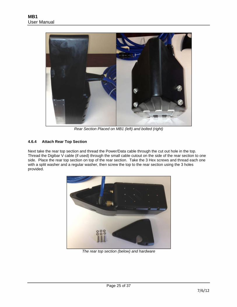
4.6.3 Attach Rear Section With the MB1 placed on it's end, slide the rear section onto the back of the MB1, with the grooved part in line with the bottom of the sonar. Thread the 4 long Hex bolts with a split ring and regular washer each. Push these bolts into the 4 holes on the back of the rear section and hand tighten using the 3/16" Hex key.
MB1 User Manual
Page 25 of 37 7/6/12
Rear Section Placed on MB1 (left) and bolted (right)
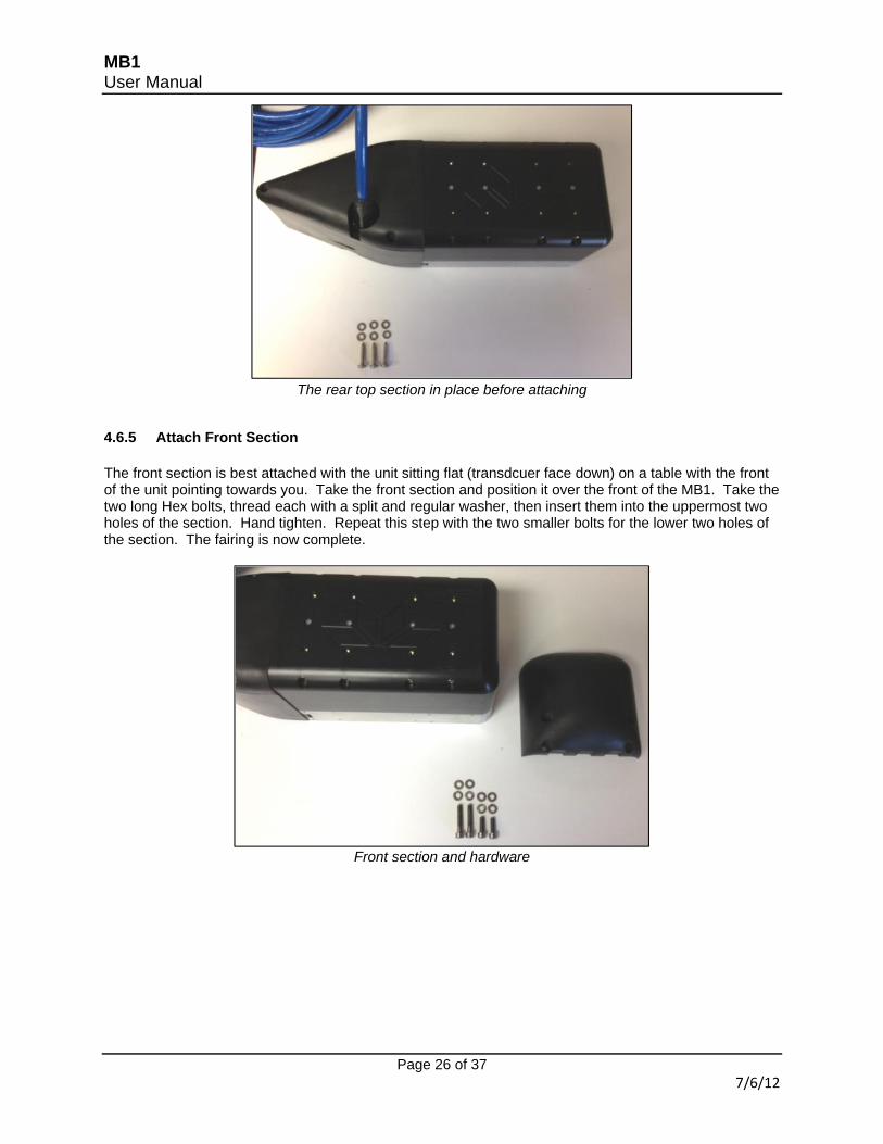
4.6.4 Attach Rear Top Section Next take the rear top section and thread the Power/Data cable through the cut out hole in the top. Thread the Digibar V cable (if used) through the small cable cutout on the side of the rear section to one side. Place the rear top section on top of the rear section. Take the 3 Hex screws and thread each one with a split washer and a regular washer, then screw the top to the rear section using the 3 holes provided.
The rear top section (below) and hardware
MB1 User Manual
Page 26 of 37 7/6/12
The rear top section in place before attaching
4.6.5 Attach Front Section The front section is best attached with the unit sitting flat (transdcuer face down) on a table with the front of the unit pointing towards you. Take the front section and position it over the front of the MB1. Take the two long Hex bolts, thread each with a split and regular washer, then insert them into the uppermost two holes of the section. Hand tighten. Repeat this step with the two smaller bolts for the lower two holes of the section. The fairing is now complete.
Front section and hardware
MB1 User Manual
Page 27 of 37 7/6/12
Front section attached
Complete Fairing
MB1 User Manual
Page 28 of 37 07/16/13
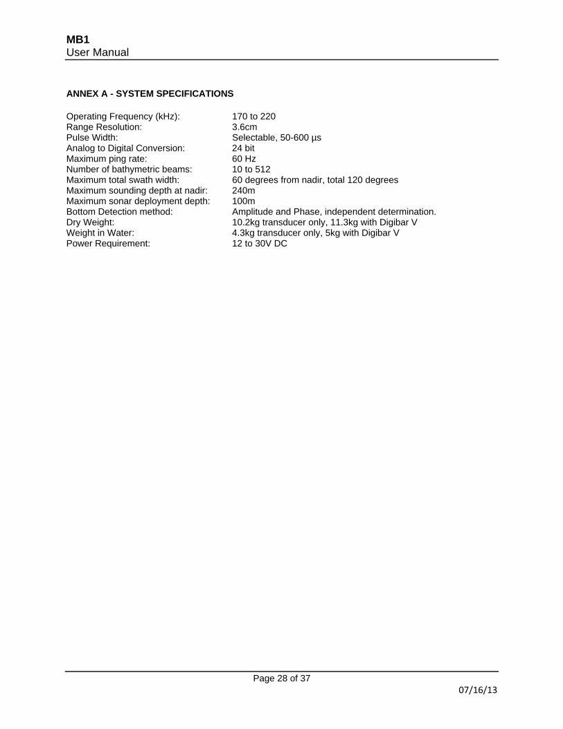
ANNEX A - SYSTEM SPECIFICATIONS Operating Frequency (kHz): 170 to 220 Range Resolution: 3.6cm Pulse Width: Selectable, 50-600 µs Analog to Digital Conversion: 24 bit Maximum ping rate: 60 Hz Number of bathymetric beams: 10 to 512 Maximum total swath width: 60 degrees from nadir, total 120 degrees Maximum sounding depth at nadir: 240m Maximum sonar deployment depth: 100m Bottom Detection method: Amplitude and Phase, independent determination. Dry Weight: 10.2kg transducer only, 11.3kg with Digibar V Weight in Water: 4.3kg transducer only, 5kg with Digibar V Power Requirement: 12 to 30V DC
MB1 User Manual
Page 29 of 37 07/16/13
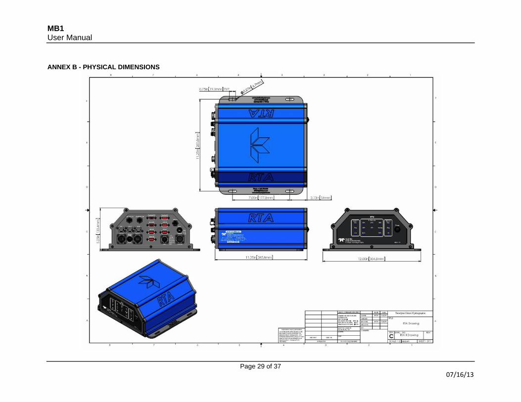
ANNEX B - PHYSICAL DIMENSIONS
MB1 User Manual
Page 30 of 37 07/16/13
MB1 User Manual
Page 31 of 37 7/6/12
MB1 User Manual
Page 32 of 37 7/6/12
MB1 User Manual
Page 33 of 37 7/6/12
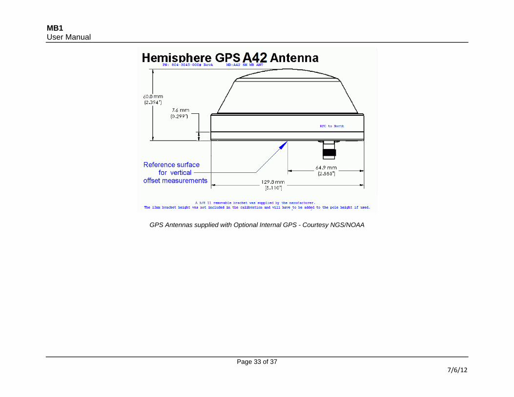
GPS Antennas supplied with Optional Internal GPS - Courtesy NGS/NOAA
MB1 User Manual
Page 34 of 37 07/16/13
ANNEX C - CABLE CONNECTORS Note: All connector views are as seen looking at the face of the cable connector on the rear of the RTA. Sonar 1 and 2
(Male connector)
Letter Color Description A Orange DA- B Orange/White DA+ C Brown DD- D Brown/White DD+ E Blue/White DB- F Blue DC- G Green DC+ H Green/White DB+ J +24V K Not used L -24V M Not used
AUX
(Female
Connector)
Letter Description A Trigger In B Trigger Out (sonar head 1) C Trigger Out (sonar head 2) D 1 PPS Out E Ground
Power + Bl + Power 24V DC + Power 24V DC + 1 Power - Bk - Power - Power - 2
Primary Comms to PC
Bl A Ch B TxA primary comms
Tx Primary Comms 3
Wh A Ch B TxB primary comms
N/A 4
Primary Comms from PC
Rd B Ch B RxA primary comms
Rx primary comms 5
Wh B Ch B RxB primary comms
Common Primary comms
6
Remote Repeater Link
Yl C Ch A TxA Remote Comms
N/A 7
Wh C Ch A TxB Remote Comms
N/A 8
Remote Repeater Link
Gn D Ch A TxA Remote Comms
N/A 9
Wh D Ch A TxB Remote Comms
N/A 10
Gyrocompass Bk E Ch C RxA Gyro Comms Rx Gyro Comms 11 Wh E Ch C RxA Gyro Comms Common Gyro
Comms 12
GPS or Doppler Log
Or F Ch C RxA GPS Comms Rx GPS Comms 13 Wh F Ch C RxB GPS Comms Common GPS
Comms 14
Ground Gn S No Connection No Connection 15 Cable screen/Sensor
Ground Cable
Screen/Sensor Ground
16
MB1 User Manual
Page 36 of 37 07/16/13
ANNEX D - COMMON ACRONYMS USED IN THIS MANUAL
1PPS One Pulse Per Second (same as PPS) A/C Alternating Current AML Data format type for real time sound velocity BNC Bayonet Neill-Concelman (type of connector) DC Direct Current dGPS Differential Global Positioning System GGA NMEA position data string GPS Global Positioning System HPR Heave Pitch Roll (motion data) I/O Input/Output LED Light Emitting Diode NMEA National Marine Electronics Association PC Personal Computer Ping A sonar transmit pulse PPS Pulse Per Second RS232 Type of serial data connector RTA Real Time Appliance SVP Sound Velocity Profiler, or Sound Velocity Profile TSPU Top Side Processing Unit (Computer used to control the multibeam) TSS1 Data format type for motion data VTG NMEA velocity data string ZDA NMEA timing data string
MB1 User Manual
Page 37 of 37 07/16/13
ANNEX E - SPARE PARTS & PART NUMBERS
Part Number Item Description Items within MB1 Scope of Supply
3029-0001-0000 MB1 multibeam sonar head 2313-0100-0000 Cable Assembly, MB1 to RTA, 15m 2811-0043-0000 Case, Transit for MB1 3017-0003-0000 Real Time Appliance for MB1 CABLEPOWDC DC Power cable 2300-0053-0000 Cable, Ethernet Cat 5 Crossover 3200-0000-0000 Manual on CD - Odom products 2811-0042-0000 Case, Transit for RTA 2010-0003-0000 Fuse, 5 Amp for RTA
Optional Power Supply 3015-0001-0000 Power Supply, Auto Switching 110/240 input and 24 VDC 150 Watt output
Optional Digibar V 3012-0102-0000 Digibar V Sound Velocity probe for MB1 1900-0164-0000 Silicone Grease, 5gm tube 81G-6002 Clamp, Digibar V 81G-6003 Spacer, Digibar V M4MM.SPLIT.TI Washer, Split Ring, M4 Titanium M4x10MM.FHSH.TI Screw, M4x07x10mm Flat Head Socket Head Cap Titanium M4x35MM.SHCS.TI Screw, M4x07x35mm Socket Head Cap Titanium M4x40MM.SHCS.TI Screw, M4x07x40mm Socket Head Cap Titanium