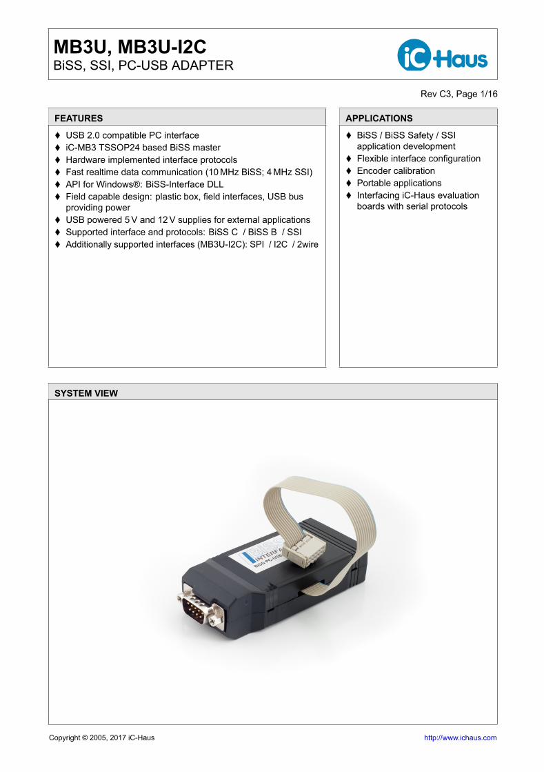
USB 2.0 compatible PC interface iC-MB3 TSSOP24 based BiSS master Hardware implemented interface protocols Fast realtime data communication (10 MHz BiSS; 4 MHz SSI) API for Windows®: BiSS-Interface DLL Field capable design: plastic box, field interfaces, USB bus
providing power USB powered 5 V and 12 V supplies for external applications Supported interface and protocols: BiSS C / BiSS B / SSI Additionally supported interfaces (MB3U-I2C): SPI / I2C / 2wire
The MB3U and MB3U-I2C adapters are USB based Windows® PC adapters. The BiSS to PC-USB adaptersenables BiSS or SSI sensors to be connected to a PC easily and at low cost. Only one BiSS to PC-USBadapters is accessible per PC system. The USB port supplies the adapter as well as the connected sensor, forwhich the 5V (up to 100 mA, through Pin 4)* and 12 V (up to 100 mA, through Pin 1)* as galvanically isolatedvoltages are available. An optional external wall power supply can also be connected to deliver other voltagesor higher currents. The BiSS/SSI communication is accomplished by differential RS422 wires with separatepotentials and cycle rates of up to 10 Mbit/sec.
The BiSS and I2C to PC-USB Adapter has an additional plug for I2C or SPI communication. The USB portsupplies the sensors via the I2C plug with 5 V (up to 100 mA, through Pin 4 - no galvanic isolation). If there isload applied to the BiSS connector, the maximum current supplied via the I2C plug is decreased. For morepower, an additional external power supply is recommended (the wall power supply does not supply the I2Cplug, see Figure 3). I2C multi-master capability is not provided.
The SPI and I2C master of MB3U-I2C are only supported by product specific APIs and software foriC-Haus product evaluation and programming.
9 Pin SUB-D Male BiSS Interface Connector Functions and Features:• Up to 3 BiSS slaves• RS422 10 MBit/s maximum data transfer rate• BiSS C unidirectional and BiSS B/C master• SSI master• I2C and SPI master (MB3U-I2C only)• BiSS master BiSS iC-MB3 TSSOP24 based• USB 2.0 compatible with up to 12 MBit/s data transfer• USB bus provides power adapter and optionally to devices• Galvanic encoder signal isolation and isolated sensor supply sourced from the USB port (+12 V and +5 V /
150 mA together)*• Plug-in power supply can be connected for sensors with higher power needs(+12 V / 500 mA, +5 V / 250 mA)*• Available 32 and 64 bit drivers for Windows®10, 8, 7, Vista, XP, 2000
The MB3U is a PC-USB interface BiSS / SSI master based on iC-MB3 TSSOP24 system design.* 150 mA for +5 V and +12 V available starting from 2008
10 Pin Pigtail 5x2 Female SPI and I2C Interface Connector Functions and Features:• SPI or I2C capable by pin connection• Up to 6 MBit/s maximum data transfer rate with SPI• 100 kBit/s maximum data transfer rate with I2C• Single master systems• Master operation based on FTDI™USB dual serial bridging device• USB 2.0 compatible with up to 12 MBit/s data transfer• USB bus provides power adapter and optionally to devices• No galvanic isolation, Sensor supply sourced from the USB port (5 V up to 200 mA)• Available 32 and 64 bit FTDI™drivers for Windows 10, 8, 7, Vista, XP, 2000
The device offered here is a multifunctional device that contains integrated BiSS C interface components. The BiSS C process isprotected by patent DE 10310622 B4 owned by iC-Haus GmbH. Users benefit from the open BiSS C protocol with a free license whichis necessary when using the BiSS C protocol in conjunction with this iC.Download the license at www.biss-interface.com/BUA
PIN CONFIGURATION BiSS / SSI (SUB-D9 male) PIN FUNCTIONSNo. Name Function
1 VB 12 V field power supply2 MA+ Clock output P3 MA- Clock output N4 VDD 5 V logic power supply5 MO- Master data output N (constant high)6 GND Ground (0 V)7 SL+ Device data input P8 SL- Device data input N9 MO+ Master data output P (constant low)
1 SCL Serial Clock Line2 GND Ground3 n.a. Reserved54 VDD 5 V logic power supply5 n.a. Reserved6 n.a. Reserved7 SDA Serial Data Line Output, short to pin 98 n.a. Reserved9 SDA Serial Data Line Input
1 SCL Serial Clock Line2 GND Ground3 n.a. Reserved4 VDD 5 V logic power supply5 n.a. Reserved6 n.a. Reserved7 MOSI Serial Data Line Output8 NCS Chip Select (low active)9 MISO Serial Data Line Input
10 GND Ground
PIN CONFIGURATION External Power Supply(DIN 45323)
PIN FUNCTIONSNo. Name Function
1 Inner Contact GND pole of external supply2 Outer Contact 12 V positive pole of
external supply (9 to 15 V DC,500 mAmax)
MB3U, MB3U-I2CBiSS, SSI, PC-USB ADAPTER
Rev C3, Page 4/16
ABSOLUTE MAXIMUM RATINGS
These ratings do not imply operating conditions; functional operation is not guaranteed. Beyond these ratings device damage may occur.Item Symbol Parameter Conditions UnitNo. Min. Max.G001 Vext External Power Supply Input 20 VG002 I(Vext) Power Supply Input Current 1 AG003 V() Voltage at input signals SL+, SL- -7 +7 VG004 I() Output Current at output signals MA+,
MA-, MO+, MO-,high -60 mAlow 60 mA(according to SN65LBC179 or compatible)
G005 P(VB) Load at VB 6 WG006 P(VDD) Load at VDD 1 WG007 GI Galvanic Isolation For BiSS and external power supply connector
(according to FT2232)G009 I() Output Current Extension cable (model MB3U-I2C only), SCL,
SCLK, SDA, NCS24 mA
(according to FT2232D or compatible)
THERMAL DATA
Item Symbol Parameter Conditions UnitNo. Min. Typ. Max.
T01 Ta Operating Temperature 0 30 °CT02 RH Relative Humidity Non condensing 5 95 %
All voltages are referenced to ground unless otherwise stated.All currents flowing into the device pins are positive; all currents flowing out of the device pins are negative.
MB3U, MB3U-I2CBiSS, SSI, PC-USB ADAPTER
Rev C3, Page 5/16
ELECTRICAL CHARACTERISTICS
Operating conditions: USB 2.0, port maximum 500 mA, Ta = 0..30 °CItem Symbol Parameter Conditions UnitNo. Min. Typ. Max.Supply001 Vusb Supply Voltage By USB port 4.5 5.0 5.5 V002 Iusb Current Consumption From USB port 500 mA003 Vext Permissible External Supply By wall adapter 9 12 15 V
Plug disconnects internal VB when plugged004 VB VB Supply Output USB powered 9 12 13 V
005 VB VB Supply Output With wall adapter (Vext = 12 V, 500 mA) Vext V
006 I(VB) Permissible VB Load Current USB powered; 150 mAload at VB of 9 pin BiSS/SSI connector;no other load at 9 pin BiSS/SSI connector(VDD, MA±, MO±);no load at 10 pin pigtail SPI/I2C
007 I(VB) Permissible VB Load Current wall adapter (12 V, 500 mA) powered; 500 mAload at VB of 9 pin BiSS/SSI connector;no load at 9 pin BiSS/SSI connector (VDD,MA±, MO±);no load at 10 pin pigtail SPI/I2C
008 VDD VDD Supply Output At 10 pin pigtail SPI/I2C and 9 pin BiSS/SSI 4.5 5 5.5 V009 I(VDD) Permissible VDD Load Current
at 10 pin pigtail SPI/I2CUSB powered; 200 mAload at VDD of 10 pin pigtail SPI/I2C;no other load 10 pin pigtail SPI/I2C (MOSI,SCL, NCS);no load at 9 pin BiSS/SSI connector
voltage at SL+ vs. SL-according to RS422 (transceiver 65LBC179) 0.2 V
106 VIT-() Negative going input thresholdvoltage at SL+ vs. SL-
according to RS422 (transceiver 65LBC179) -0.2 V
107 VHYST Hysteresis voltage according to RS422 (transceiver 65LBC179) 45 mV108 Rin() Input Termination at SL+ vs. SL- 120 Ω
MB3U, MB3U-I2CBiSS, SSI, PC-USB ADAPTER
Rev C3, Page 6/16
ELECTRICAL CHARACTERISTICS
Operating conditions: USB 2.0, port maximum 500 mA, Ta = 0..30 °CItem Symbol Parameter Conditions UnitNo. Min. Typ. Max.Extension Cable (MB3U-I2C pigtail cable only)201 Vin() Input Switching Threshold
Voltage at SDA (MISO)Standard level 1.2 1.3 1.5 V(according to FT2232)
202 Vhyst() Input Switching HysteresisVoltage at SDA
Standard level 50 30 25 mV(according to FT2232)
203 Vo()hi Output Voltage high at SCL,SCLK, SDA
I(source) = -2 mA, standard level 3.2 4.1 4.9 V(according to FT2232)
204 Vo()lo Output Voltage high at SCL,SCLK, SDA
I(sink) = 2 mA, standard level 0.3 0.4 0.6 V(according to FT2232)
MB3U, MB3U-I2CBiSS, SSI, PC-USB ADAPTER
Rev C3, Page 7/16
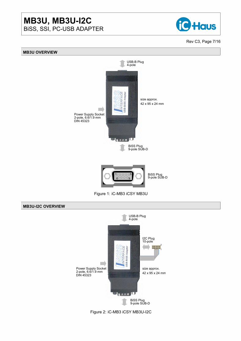
MB3U OVERVIEW
42 x 95 x 24 mm
BiSS Plug9-pole SUB-D
USB-B Plug
2-pole, 6.6/1.9 mmPower Supply Socket
4-pole
DIN 45323
size approx.
1
96
5 BiSS Plug9-pole SUB-D
Figure 1: iC-MB3 iCSY MB3U
MB3U-I2C OVERVIEW
42 x 95 x 24 mm
BiSS Plug9-pole SUB-D
size approx.2-pole, 6.6/1.9 mmPower Supply Socket
10-pole
DIN 45323
I2C Plug
USB-B Plug4-pole
1
2
Figure 2: iC-MB3 iCSY MB3U-I2C
MB3U, MB3U-I2CBiSS, SSI, PC-USB ADAPTER
Rev C3, Page 8/16
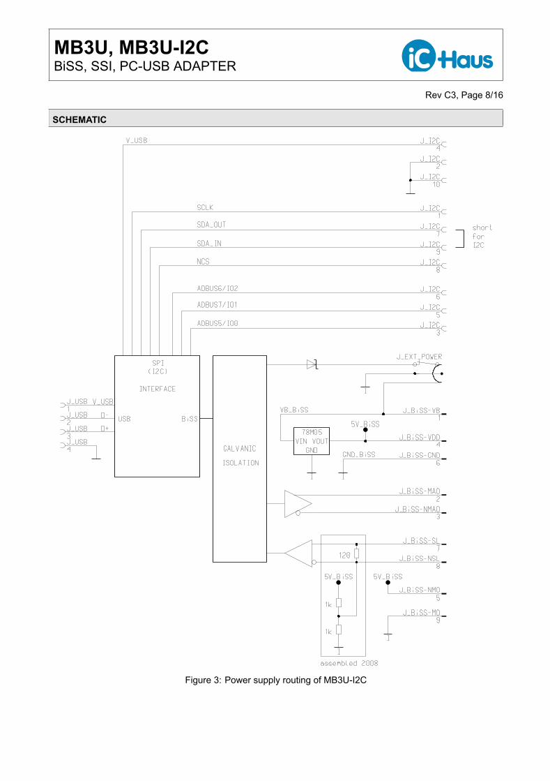
SCHEMATIC
Figure 3: Power supply routing of MB3U-I2C
MB3U, MB3U-I2CBiSS, SSI, PC-USB ADAPTER
Rev C3, Page 9/16
APPLICATION SOFTWARE
The BiSS reader software is a good and generic tool to access position and register data of BiSS devices. TheBiSS reader software can be used on PCs with Windows operating systems, as well as the BiSS interface DLLand the required USB driver for available adapters. Installers for the BiSS reader software software, the BiSSInterface DLL and USB drivers for the adapters are available as a downloadable ZIP file.Download from http://www.ichaus.de/software
For iC-Haus iC devices easy to use product specific evaluation software is also available and can be used toaccess, configure and calibrate. Installers for product specific evaluation software, the product specific DLLs andUSB drivers for the adapters are available as a downloadable ZIP file.Download from http://www.ichaus.de/software
Download from http://www.ichaus.de/MB3U_driver
InstallationAfter unzipping the Driver ZIP, the driver executable file(s) are located in the selected directory.Note: Administrator rights are required to run installation.
The BiSS software for PCs running on Windows operating systems is available as an installer. Download fromhttp://www.ichaus.de/BiSS_gui_rte
See also the iC-Haus software overview http://www.ichaus.de/software
1. USB driver need to be installed to access the BiSS PC Adapter. Execute the executable in the driver installationpackage and follow the on-screen instructions. This process can take a few minutes.
2. The installation of the BiSS software starts by executing the installer. Follow the on-screen instructions to finishthe installation procedure.
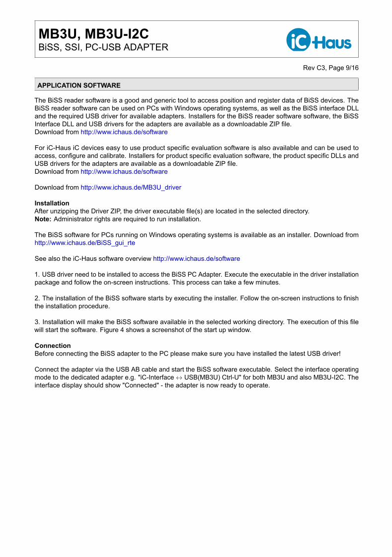
3. Installation will make the BiSS software available in the selected working directory. The execution of this filewill start the software. Figure 4 shows a screenshot of the start up window.
ConnectionBefore connecting the BiSS adapter to the PC please make sure you have installed the latest USB driver!
Connect the adapter via the USB AB cable and start the BiSS software executable. Select the interface operatingmode to the dedicated adapter e.g. "iC-Interface ↔ USB(MB3U) Ctrl-U" for both MB3U and also MB3U-I2C. Theinterface display should show "Connected" - the adapter is now ready to operate.
Top Button and Check Box DescriptionButton DescriptionDisconnected/Connected Indicates and allocates/disallocates the adapter hardwareRead SCD Reads in sensor dataCheck Box DescriptionContinuous Reads in sensor data continuously and read data is displayed in the
SCD contentSave Saves sensor data to file with reading SCD data continuously
Figure 4: Start screen with connected adapter
MB3U, MB3U-I2CBiSS, SSI, PC-USB ADAPTER
Rev C3, Page 11/16
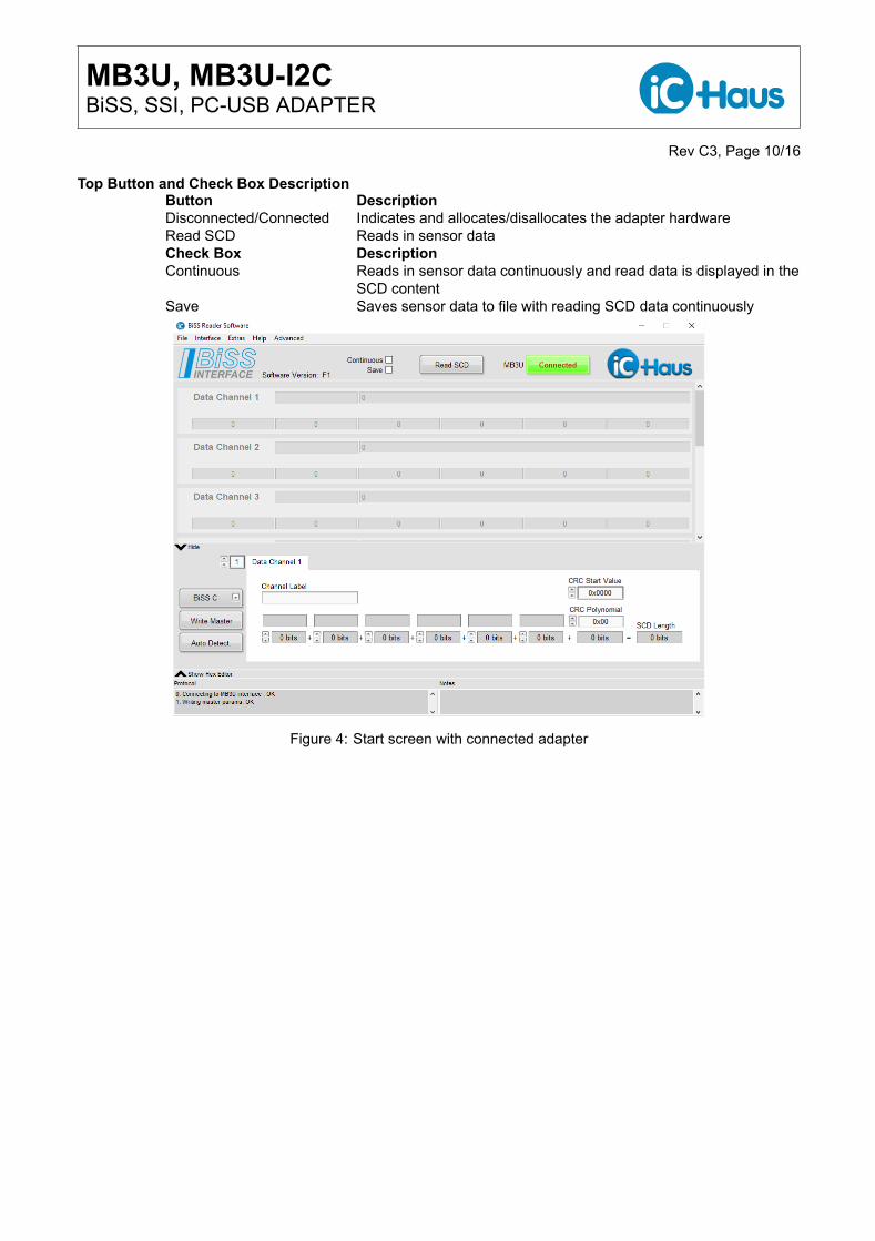
ConfigurationTo set the BiSS Master for the sensor(s) connected to it, select Config Slaves and manually configure the BiSSparameters (data lengths, CRC polynomials, etc.) according to the sensor’s data sheet.
Auto Detection of the Connected Device ConfigurationBiSS permits different possibilities and detail levels for an automatic detection of the connected device configura-tion.
Implemented Auto Detection functions:
• Custom Auto Detection with selected XML file path• Auto Detection via BiSS EDS• Auto Detection via BiSS ID and standard BiSS XML file path• Auto Detection via BiSS Profile ID
Figure 5: Automatic Detection
BiSS XML FilesThe file "idbiss6943.xml" is a BiSS device description file for BiSS slave iCs of iC-Haus. Further XML files areintegrated with the date of the software release. For possible updates and new XML files please contact themanufacturer of your sensor for an appropriate device description file or set the transmission parameters yourselflater. See also at the BiSS website in the identifier section for published XML files http://www.biss-interface.com .
BiSS Reader Configuration FilesTransmission parameter settings can be stored to a *.cfg file for later use with the BiSS software.Those configuration files can be imported by API(DLL) functions.
Master Configuration FilesThe "Save BiSS-Master-Config" writes an BiSS Master Chip configuration description into a *.txt file (e. g. setupof iC-MB3, MB100). Those BiSS master configuration files can be integrated into configuration code sets forprogramming BiSS master iC´s or iP´s to a dedicated BiSS setup.
BiSS Reader Software Menu ItemsDescription of Menu Section
<File> Save Config File Writes BiSS transmission parameter settings to fileLoad Config File Loads BiSS transmission parameter settings from fileSave Master Config Writes an interface configuration description to fileExit Quit software
<Interface> No Hardware Switch to no hardware to deallocate an adapteriC-Interface ↔ USB(MB3U) Ctrl-U For use with BiSS PC-USB adapter MB3U and MB3U-I2CiC-Interface ↔ USB(MB4U) Ctrl-4 For use with BiSS PC-USB adapter MB4UiC-Interface ↔ USB(MB5U) Ctrl-5 For use with BiSS PC-USB adapter MB5U
<Extras> Generate Report Exports software screens, log book text and configurationinto a single ZIP file for support purpose
Reset User Preferences Reset all user preferences of the BiSS software
<Help> BiSS homepage Opens the link www.BiSS-Interface.com in Your browserBiSS datasheet Opens the BiSS protocol description link in Your browser
<Advanced> Fast Reader Opens the Fast Reader sub window, only for use with BiSSPC-USB adapter MB4U or MB5U
EDS Editor Opens the BiSS EDS viewer and editor sub windowMath Analysis Opens the BiSS math analysis sub windowInitializes the BiSS bus communication Initializes the BiSS Interface channel
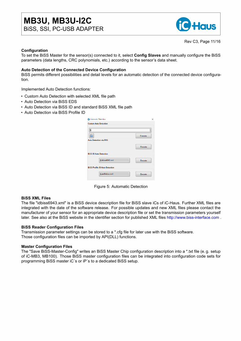
SCD Configuration Button and Selector Button DescriptionWrite Master Transfers configuration updates to the allocated adapterAuto Detect. Automatic detection and identification of connected BiSS sensor(s)
SCD configurationBiSS C/B/SSI Selects the required protocol
Figure 6: Single Cycle Data Screen
MB3U, MB3U-I2CBiSS, SSI, PC-USB ADAPTER
Rev C3, Page 13/16
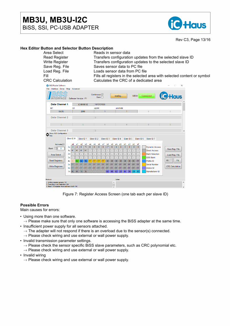
Hex Editor Button and Selector Button DescriptionArea Select Reads in sensor dataRead Register Transfers configuration updates from the selected slave IDWrite Register Transfers configuration updates to the selected slave IDSave Reg. File Saves sensor data to PC fileLoad Reg. File Loads sensor data from PC fileFill Fills all registers in the selected area with selected content or symbolCRC Calculation Calculates the CRC of a dedicated area
Figure 7: Register Access Screen (one tab each per slave ID)
Possible ErrorsMain causes for errors:
• Using more than one software.→ Please make sure that only one software is accessing the BiSS adapter at the same time.
• Insufficient power supply for all sensors attached.→ The adapter will not respond if there is an overload due to the sensor(s) connected.→ Please check wiring and use external or wall power supply.
• Invalid transmission parameter settings.→ Please check the sensor specific BiSS slave parameters, such as CRC polynomial etc.→ Please check wiring and use external or wall power supply.
• Invalid wiring→ Please check wiring and use external or wall power supply.
MB3U, MB3U-I2CBiSS, SSI, PC-USB ADAPTER
Rev C3, Page 14/16
REVISION HISTORY
Rel. Rel. Date∗ Chapter Modification PageA1 2005-02-08 First release
Rel. Rel. Date∗ Chapter Modification PageA4 2007-10-05 Update all
Rel. Rel. Date∗ Chapter Modification PageA5 2007-10-08 FEATURES Update of MB3U technical data, MB3U-I2C, software description all
Rel. Rel. Date∗ Chapter Modification PageA6 2009-11-09 FEATURES Update of MB3U-I2C optional SPI interface functionality all
Rel. Rel. Date∗ Chapter Modification PageB1 2010-01-21 ORDERING INFORMATION iC-MB3 iCSY MB3U-PS230 and iC-MB3 iCSY MB3U-I2C-PS230 added 1
ORDERING INFORMATION Scope of delivery: wall power supply removed 1
Rel. Rel. Date∗ Chapter Modification PageB2 2010-05-03 FEATURES BiSS plug pin configuration table format updated 1
FEATURES I2C plug pin configuration For I2C header updated 2FEATURES I2C plug pin configuration For SPI header updated 2FEATURES 100 mA for +5 V and +12 V available starting from 2008 added 2
Rel. Rel. Date∗ Chapter Modification PageB3 2013-02-27 FEATURES BUA info added 1
APPLICATION SOFTWARE BiSS software download updated 4APPLICATION SOFTWARE Installation instructions updated 4 . . . 5APPLICATION SOFTWARE BiSS Software details updated to software revision D2 4 . . . 5
Rel. Rel. Date∗ Chapter Modification PageB5 2014-02-04 FEATURES Figure 3: Power supply routing of MB3U-I2C updated 3
FEATURES More details on the I2C/SPI interface connector 4
Rel. Rel. Date∗ Chapter Modification PageB6 2015-06-03 FEATURES iC-MB3z no more relevance, removed 1
FEATURES BiSS B, BiSS C and SSI protocols added 1APPLICATION SOFTWARE MB5U updated 4APPLICATION SOFTWARE BiSS software details updated to software revision E8 6 . . . 8APPLICATION SOFTWARE iC-Interface ↔ LPT(MB3A) BiSS PC adapter MB3A no more relevance, removed 7
Rel. Rel. Date∗ Chapter Modification PageC1 2017-03-07 Datasheet revised all
APPLICATION SOFTWARE BiSS Reader details updated to the all new BiSS Reader F1 release 8 . . . 12
Rel. Rel. Date∗ Chapter Modification PageC2 2017-05-26 CONNECTORS 12 V replaced by 5 V logic power supply at I2C 3
Rel. Rel. Date∗ Chapter Modification PageC3 2017-07-19 ORDERING INFORMATION ORDERING INFORMATION retrieved 16
∗ Release Date format: YYYY-MM-DD
MB3U, MB3U-I2CBiSS, SSI, PC-USB ADAPTER
Rev C3, Page 15/16
iC-Haus expressly reserves the right to change its products and/or specifications. An Infoletter gives details as to any amendments and additions made to therelevant current specifications on our internet website www.ichaus.com/infoletter and is automatically generated and shall be sent to registered users by email.Copying – even as an excerpt – is only permitted with iC-Haus’ approval in writing and precise reference to source.
The data specified is intended solely for the purpose of product description and shall represent the usual quality of the product. In case the specifications containobvious mistakes e.g. in writing or calculation, iC-Haus reserves the right to correct the specification and no liability arises insofar that the specification was froma third party view obviously not reliable. There shall be no claims based on defects as to quality in cases of insignificant deviations from the specifications or incase of only minor impairment of usability.No representations or warranties, either expressed or implied, of merchantability, fitness for a particular purpose or of any other nature are made hereunderwith respect to information/specification or the products to which information refers and no guarantee with respect to compliance to the intended use is given. Inparticular, this also applies to the stated possible applications or areas of applications of the product.
iC-Haus products are not designed for and must not be used in connection with any applications where the failure of such products would reasonably beexpected to result in significant personal injury or death (Safety-Critical Applications) without iC-Haus’ specific written consent. Safety-Critical Applicationsinclude, without limitation, life support devices and systems. iC-Haus products are not designed nor intended for use in military or aerospace applications orenvironments or in automotive applications unless specifically designated for such use by iC-Haus.iC-Haus conveys no patent, copyright, mask work right or other trade mark right to this product. iC-Haus assumes no liability for any patent and/or other trademark rights of a third party resulting from processing or handling of the product and/or any other use of the product.
Software and its documentation is provided by iC-Haus GmbH or contributors "AS IS" and is subject to the ZVEI General Conditions for the Supply of Productsand Services with iC-Haus amendments and the ZVEI Software clause with iC-Haus amendments (www.ichaus.com/EULA).