//Use only when card type = AC_SCModule BYTE ATRLen; // Length of the ATR BYTE ATR[128]; // ATR string BYTE HistLen; // Length of the Historical data BYTE HistOffset; // Offset of the Historical data
// from the beginning of ATR INT16 APDULenMax; // Max. APDU supported
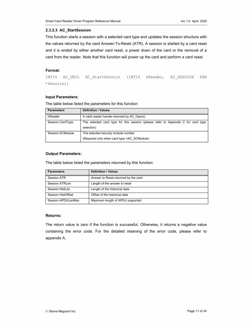
} AC_SESSION; The AC_SESSION data structure is used in the AC_StartSession function call for the retrieval
of ATR information from the smart card. Before calling AC_StartSession, the program needs
to specify the value of CardType. After calling the function, the ATR string can be found in
ATR field and the length is stored in ATRLen.
Name Input/Output Description
CardType I The card type selected for operation (refer to Appendix C for
CardType)
SCModule I The security module selected for operation. (The value is used only
when card type = AC_SCModule)
ATRLen O Length of the ATR string
ATR O Attention to reset (ATR) string
HistLen O Obsolete field – not used anymore
HistOffset O Obsolete field – not used anymore
APDULenMax O Obsolete field - not used anymore
2.3.1.4 AC_INFO typedef struct {
INT16 nMaxC; // Maximum number of command data bytes INT16 nMaxR; // Maximum number of data bytes that
Smart Card Reader Driver Program Reference Manual rev 1.0 April, 2002
Silone Magcard Inc. Page 8 of 34
// can be requested in a response INT16 CType; // The card types supported by the reader BYTE CStat; // The status of the card reader BYTE CSel; // The current selection of card type BYTE szRev[10]; // The 10 bytes firmware type and
// revision code INT16 nLibVer; // Library version Long lBaudRate; // Current Running Baud Rate
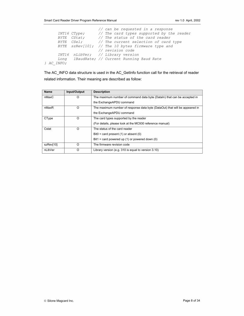
} AC_INFO; The AC_INFO data structure is used in the AC_GetInfo function call for the retrieval of reader
related information. Their meaning are described as follow:
Name Input/Output Description
nMaxC O The maximum number of command data byte (DataIn) that can be accepted in
the ExchangeAPDU command
nMaxR O The maximum number of response data byte (DataOut) that will be appeared in
the ExchangeAPDU command
CType O The card types supported by the reader
(For details, please look at the MC930 reference manual)
Cstat O The status of the card reader
Bit0 = card present (1) or absent (0)
Bit1 = card powered up (1) or powered down (0)
szRev[10] O The firmware revision code
nLibVer O Library version (e.g. 310 is equal to version 3.10)
Smart Card Reader Driver Program Reference Manual rev 1.0 April, 2002
Silone Magcard Inc. Page 9 of 34
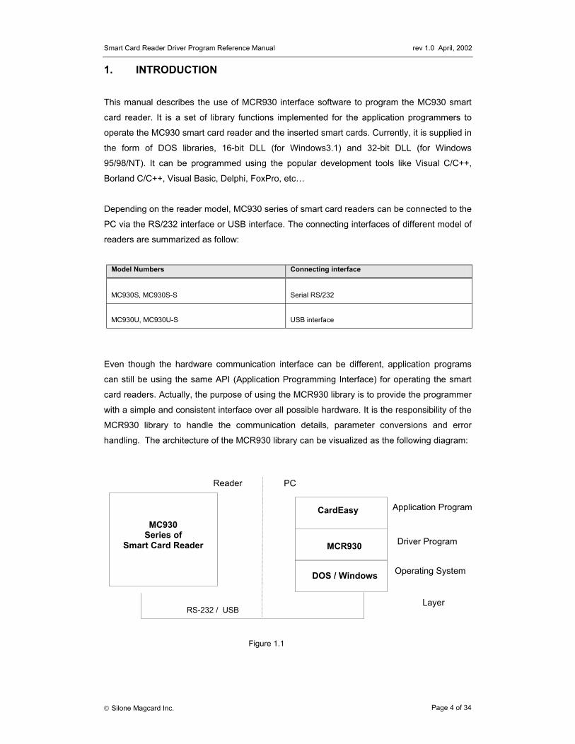
2.3.2 Interface Function Prototypes Generally, a program is required to call AC_Open first to obtain a handle. The handle is
required for subsequent calls to AC_StartSession, AC_ExchangeAPDU, AC_EndSession and
AC_Close. The inserted card can be powered up by using the AC_StartSession function and
card commands can be exchanged with the inserted card using the AC_ExchangeAPDU
function. Moreover, AC_SetOptions and AC_GetInfo are two commands that can be used to
set and read the various information of the reader.
2.3.2.1 AC_Open This function opens a port and returns a valid reader handle for the application program.
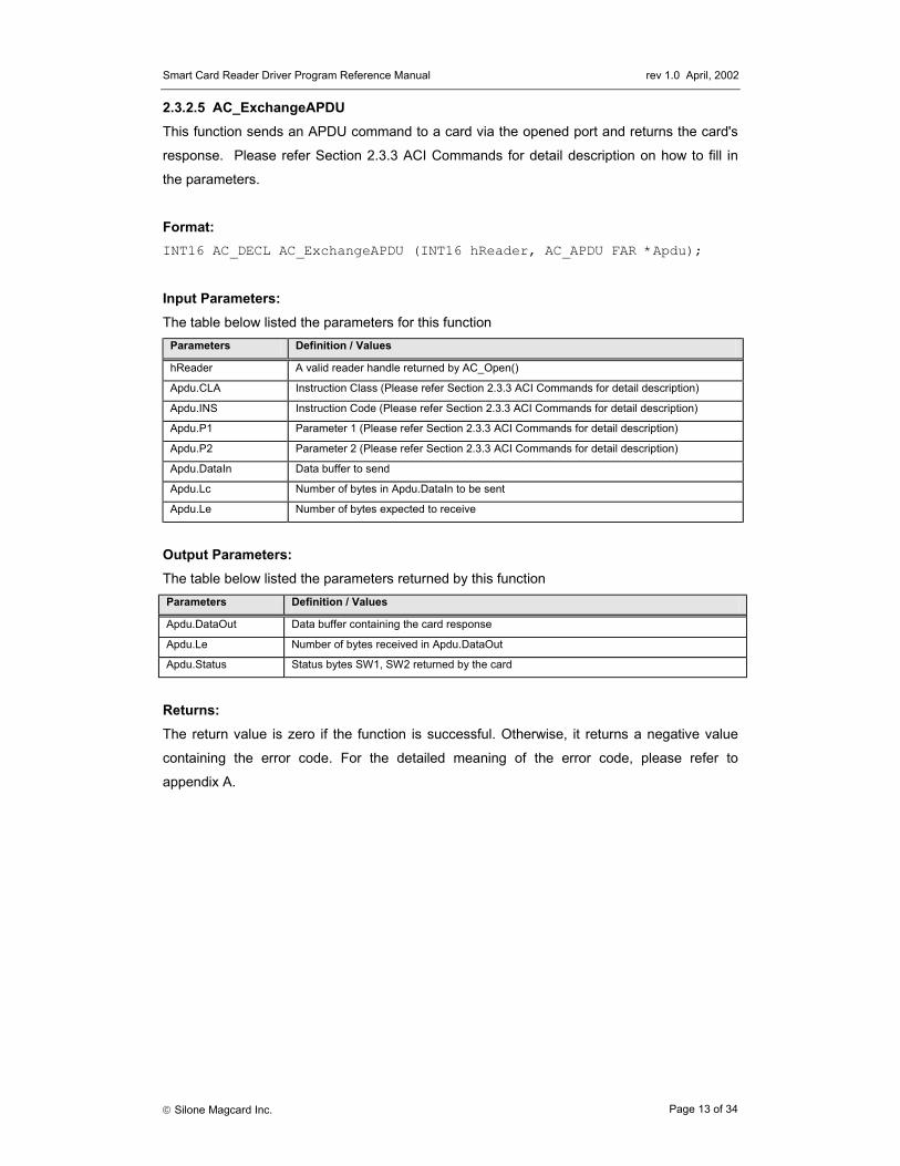
Output Parameters: The table below listed the parameters returned by this function Parameters Definition / Values
Apdu.DataOut Data buffer containing the card response
Apdu.Le Number of bytes received in Apdu.DataOut
Apdu.Status Status bytes SW1, SW2 returned by the card
Returns: The return value is zero if the function is successful. Otherwise, it returns a negative value
containing the error code. For the detailed meaning of the error code, please refer to
appendix A.
Smart Card Reader Driver Program Reference Manual rev 1.0 April, 2002
Silone Magcard Inc. Page 14 of 34
Examples: // Read 8 bytes from AM104 starting from address 0 INT16 RtnCode,i; AC_APDU Apdu; Apdu.CLA = 0x00; // Instruction Class Apdu.INS = ACI_Read; // Command Apdu.P1 = 0x00; // MSB of starting address Apdu.P2 = 0x00; // LSB of starting address Apdu.Lc = 0x00; // No input data for this command Apdu.Le = 0x08; // Read 8 bytes data //Exchange APDU with the MC930 reader RtnCode = AC_ExchangeAPDU(hReader, &Apdu); if (RtnCode >= 0) { // print the data printf("Data : "); for (i=0; i < (INT16) Apdu.Le; i++) printf(" %02X",Apdu.DataOut[i]); // print the status bytes printf("Card Status(SW1 SW2)=%04X",Apdu.Status);
2.3.2.6 AC_GetInfo This function retrieve information related to the currently selected reader.
Format : INT16 AC_DECL AC_GetInfo (INT16 hReader, AC_INFO FAR *Info);
Input Parameters: The table below lists the parameters for this function
Parameters Definition / Values
hReader A valid reader handle returned by AC_Open()
Output Parameters: The table below lists the parameters returned by this function
Parameters Definition / Values
Info.szRev Revision code for the selected reader.
Info.nMaxC The maximum number of command data bytes.
Info.nMaxR The maximum number of data bytes that can be requested to be transmitted in a
response
Info.CType The card types supported by this reader
Info.CStat The current status of the reader
00H = no card inserted
01H = card inserted, not powered up
03H = card powered up
Info.CSel The currently selected card type
Info.nLibVer Current library version
(e.g. 310 is equal to version 3.10)
Smart Card Reader Driver Program Reference Manual rev 1.0 April, 2002
Silone Magcard Inc. Page 15 of 34
Parameters Definition / Values
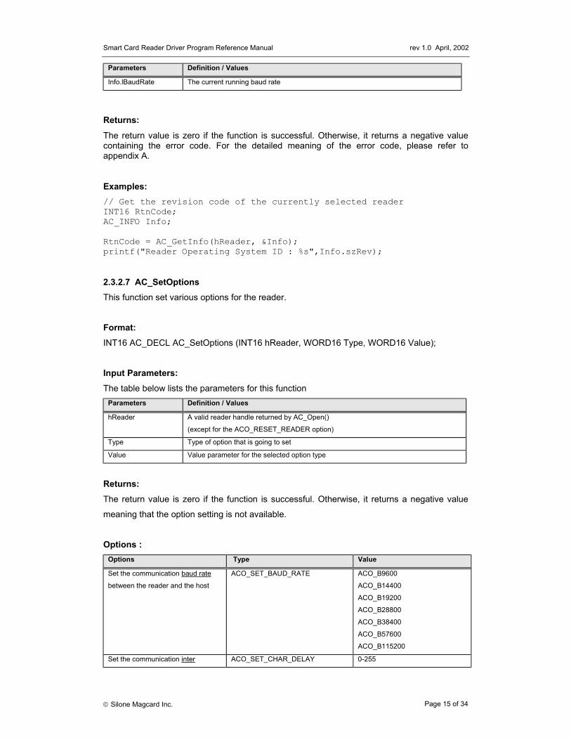
Info.lBaudRate The current running baud rate
Returns: The return value is zero if the function is successful. Otherwise, it returns a negative value containing the error code. For the detailed meaning of the error code, please refer to appendix A.
Examples: // Get the revision code of the currently selected reader INT16 RtnCode; AC_INFO Info; RtnCode = AC_GetInfo(hReader, &Info); printf("Reader Operating System ID : %s",Info.szRev);
2.3.2.7 AC_SetOptions This function set various options for the reader.
Input Parameters: The table below lists the parameters for this function
Parameters Definition / Values
hReader A valid reader handle returned by AC_Open()
(except for the ACO_RESET_READER option)
Type Type of option that is going to set
Value Value parameter for the selected option type
Returns: The return value is zero if the function is successful. Otherwise, it returns a negative value
meaning that the option setting is not available.
Options :
Options Type Value
Set the communication baud rate
between the reader and the host
ACO_SET_BAUD_RATE ACO_B9600
ACO_B14400
ACO_B19200
ACO_B28800
ACO_B38400
ACO_B57600
ACO_B115200
Set the communication inter ACO_SET_CHAR_DELAY 0-255
Smart Card Reader Driver Program Reference Manual rev 1.0 April, 2002
Silone Magcard Inc. Page 16 of 34
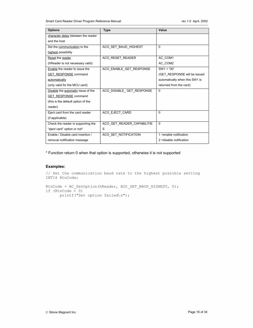
Options Type Value
character delay between the reader
and the host
Set the communication to the
highest possibility
ACO_SET_BAUD_HIGHEST 0
Reset the reader
(hReader is not necessary valid)
ACO_RESET_READER AC_COM1
AC_COM2
Enable the reader to issue the
GET_RESPONSE command
automatically
(only valid for the MCU card)
ACO_ENABLE_GET_RESPONSE SW1 + “00”
(GET_RESPONSE will be issued
automatically when this SW1 is
returned from the card)
Disable the automatic issue of the
GET_RESPONSE command
(this is the default option of the
reader)
ACO_DISABLE_ GET_RESPONSE 0
Eject card from the card reader
(if applicable)
ACO_EJECT_CARD 0
Check the reader is supporting the
“eject card” option or not*
ACO_GET_READER_CAPABILITIE
S
0
Enable / Disable card insertion /
removal notification message
ACO_SET_NOTIFICATION 1 =enable notification
2 =disable notification
* Function return 0 when that option is supported, otherwise it is not supported Examples: // Set the communication baud rate to the highest possible setting INT16 RtnCode; RtnCode = AC_SetOption(hReader, ACO_SET_BAUD_HIGHEST, 0); if (RtnCode < 0)
printf("Set option failed\n");
Smart Card Reader Driver Program Reference Manual rev 1.0 April, 2002
Silone Magcard Inc. Page 17 of 34
2.3.3 ACI Commands ACI Commands are provided to support the standard operation of a wide range of memory
cards. Because of the different nature of different memory cards and their capabilities, not all
the commands are available for every card type. Appendix B listed the available ACI
commands for different card types.
The ACI Commands described here are used in the AC_ExchangeAPDU function call. Proper
parameter values of different ACI commands should be initialized in the AC_APDU structure
before calling the AC_ExchangeAPDU function. Upon successful completion of the function,
the application program is required to check the card return status (SW1 SW2) in AC_APDU
and retrieve the output result from the DataOut buffer accordingly.
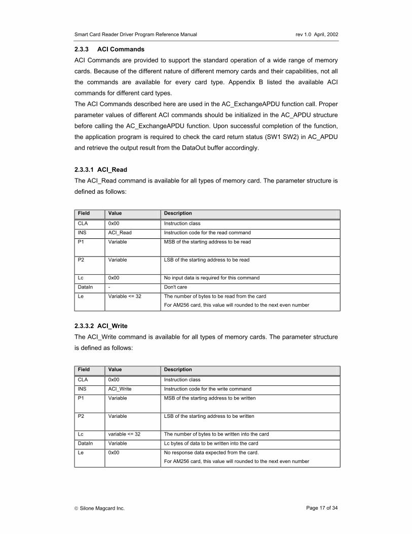
2.3.3.1 ACI_Read The ACI_Read command is available for all types of memory card. The parameter structure is
defined as follows:
Field Value Description
CLA 0x00 Instruction class
INS ACI_Read Instruction code for the read command
P1 Variable MSB of the starting address to be read
P2 Variable LSB of the starting address to be read
Lc 0x00 No input data is required for this command
DataIn - Don't care
Le Variable <= 32 The number of bytes to be read from the card
For AM256 card, this value will rounded to the next even number
2.3.3.2 ACI_Write The ACI_Write command is available for all types of memory cards. The parameter structure
is defined as follows:
Field Value Description
CLA 0x00 Instruction class
INS ACI_Write Instruction code for the write command
P1 Variable MSB of the starting address to be written
P2 Variable LSB of the starting address to be written
Lc variable <= 32 The number of bytes to be written into the card
DataIn Variable Lc bytes of data to be written into the card
Le 0x00 No response data expected from the card.
For AM256 card, this value will rounded to the next even number
Smart Card Reader Driver Program Reference Manual rev 1.0 April, 2002
Silone Magcard Inc. Page 18 of 34
2.3.3.3 ACI_WriteCarry The ACI_WriteCarry command is available for EEPROM non-reloadable token counter cards.
The parameter structure is defined as follows:
Name Value Description
CLA 0x00 Instruction class
INS ACI_WriteCarry Instruction code for the write carry command
P1 0x01,0x02 or 0x03 0x01 = write carry without backup
0x02 = write with backup
0x03 = write carry with backup
P2 Variable LSB of the starting address to be written
Lc 0x01 Only one byte at a time is allowed for this command
DataIn Variable DataIn[0] contains the byte that is to be written into the card
Le 0x00 No response data expected from the card
2.3.3.4 ACI_WritePr The ACI_WritePr command is available for some memory cards with protected memory logic.
The parameter structure is defined as follows:
Name Value Description
CLA 0x00 Instruction class
INS ACI_WritePr Instruction code for the write protect command
P1 Variable MSB of the starting address to be written
P2 Variable LSB of the starting address to be written
Lc variable <= 32 The number of bytes to be written into the card
DataIn Variable Lc bytes of data to be written into the card
Le 0x00 No response data expected from the card
2.3.3.5 ACI_Erase The ACI_Erase command is available for some memory cards with the erasing capability. The
parameter structure is defined as follows:
Name Value Description
CLA 0x00 Instruction class
INS ACI_Erase Instruction code for the erase command
P1 Variable MSB of the starting address to be erased
P2 Variable LSB of the starting address to be erased
Lc variable <= 32 The number of bytes to be erased from the card
DataIn - Don't care
Le 0x00 No response data expected from the card
Smart Card Reader Driver Program Reference Manual rev 1.0 April, 2002
Silone Magcard Inc. Page 19 of 34
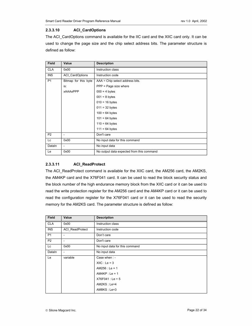
2.3.3.6 ACI_ChangePIN The ACI_ChangePIN command is available for the AM2KS / X76F041 / X76F128 / X76F640
card. For the AM8KS, it is required to use the ACI_Write command to do the change PIN
operation. The parameter structure of ACI_ChangePIN is defined as follows:
Field Name
Value Description
CLA 0x00 Instruction class
INS ACI_ChangePIN Instruction code for the change PIN command
P1 variable Please refer to the table in command ACI_Verify for the definition of this field
P2 - Don't Care
Lc variable The length of the PIN
DataIn variable The new PIN value
Le 0x00 No response data expected from the card
In order for the password (PIN) of X76F041 card can be changed, the application must verify
the old password correctly before the ACI_ChangePIN command can be executed. If the read
password is verified, only the read password can be changed. If the write password is
verified, only the write password can be changed. However, when the configuration password
is verified, all three passwords can be changed.
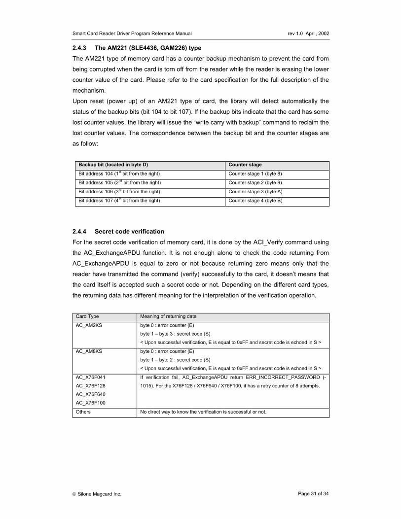
2.3.3.7 ACI_Verify The ACI_Verify command is available for some memory cards with the secret code capability.
It is not enough to check alone the code returned from the function AC_ExchangeAPDU to
determine that the verification is successful or not. Application program must check the data
returning back from the card for the interpretation of whether the verification is successful or
not. Please see the programmer notes for detail.
Field Value Description
CLA 0x00 Instruction class
INS ACI_Verify Instruction code for the verify command
P1 variable Key Index, see the table below for the description
P2 - Don't Care
Lc variable Number of bytes of the key
DataIn variable Lc bytes of key value to be verified by the card
Le variable Case when : -
AC_AM2KS : Le = 4
AC_AM8KS : Le = 3
otherwise : Le = 0
Smart Card Reader Driver Program Reference Manual rev 1.0 April, 2002
Silone Magcard Inc. Page 20 of 34
Depending on the card type of the current session, Key Index (P1) can contain any of the
Password”, “Write Array 1 Password” and “Reset Password”.
In order to read (ACI_Read) the memory content of Array0, the application must have the
“Read Array 0 Password” verify (ACI_Verify) OK. Similarly, for the writing (ACI_Write) of data
into the memory content of Array0, the application must have the “Write Array 0 Password”
verify OK. The same restriction is applied also in the case of Array1. For the “Reset
Password”, once it is verified OK, the command “ACI_WriteAll” can be used to write the
complete card content with zero and the command “ACI_CardReset” can be used to reset the
retry counter and reactive the card. When a password is verified OK, it can be changed using
the “ACI_ChangePIN” command.
For the X76F128, array 0 can be accessed in the address range $0000 - $3FFF and array 1
can be accessed in the address range $8000 - $803F. For the X76F640, array 0 can be
accessed in the address range $0000 - $1FFF and array 1 can be accessed in the address
range $8000 - $801F.
2.4.6 The Xicor Card X76F100 The X76F100 memory array consists of fourteen 8-byte sectors (total 112 bytes) in which the
reading is protected by a 8-byte read password and the writing is protected by a 8-byte write
password. Write access to the array always begins at the first address of the sector (i.e.
address is a multiple of 8) and the length must be a multiple of 8. The retry counter allows 8
accesses with an invalid password. If the retry counter overflows, the memory area and both
of the passwords are cleared to zero. If a correct password is received prior to retry counter
overflow, the retry counter is reset and access is granted. For the changing of either one of
the password (ACI_ChangePIN), it is required to have the write password to be verified OK.
Smart Card Reader Driver Program Reference Manual rev 1.0 April, 2002
Silone Magcard Inc. Page 33 of 34
Appendix A : Table of error codes Code Meaning
-603 Error in the reader handle
-600 Session parameter is null
-108 No free handle left for allocation
-100 Selected port is invalid
-101 Selected reader is invalid
-102 Selected port is occupied
-1001 No card type selected
-1002 No card is inserted
-1003 Wrong card type
-1004 Card not powered up
-1005 INS is invalid
-1006 Card failure
-1007 Protocol error
-1008 Card type not supported
-1009 Incompatible command
-1010 Error in address
-1011 Data length error
-1012 Error in response length
-1013 Secret code locked
-1014 Invalid SC module number
-1015 Incorrect password
-1050 Error in CLA
-1051 Error in APDU parameters
-1052 Communication buffer is full
-1053 Address not align with word boundary
-1080 Protocol frame error
-1081 No response from reader
-1082 Error found in the calling function’s parameters
-1083 Specified function not supported
-1084 Connector short circuit
-1085 Unexpected internal error
-1086 A required DLL file is missing
-1099 Unknown response
-2000 USB internal error
-2001 Error in memory allocation
-2002 Error in linking USB library
-2003 Error in locating window system directory
-3000 Error found in PCSC smart card manager
Smart Card Reader Driver Program Reference Manual rev 1.0 April, 2002
Silone Magcard Inc. Page 34 of 34
Appendix B : Supporting Memory Card Commands
CardType
ACI_R
eadAC
I_Write
ACI_SetFuse
ACI_Verify
ACI_W
ritePrAC
I_ChangePIN
ACI_Erase
ACI_W
riteCarry
ACI_Authenticate
ACI_SetProtect
ACI_R
eadRrotect
ACI_SetH
EAC
I_LockProtectAC
I_ClearProtect
ACI_W
riteAllAC
I_EraseAllAC
I_Reactivate
ACI_C
ardOptions
ACI_Blow
Fuse
AC_AM104 X X X XAC_AM221 X X X X XAC_SLE4404 X X X X XAC_GPM896 X X X X XAC_AT101 X X X X X XAC_AT102 X X X X X XAC_AT8KP X X XAC_AT8KS X X X X XAC_AT2KP X X XAC_AT2KS X X X X X XAC_IIC X X XAC_XIIC X X X X X XAC_AT1604 X X X X X XAC_T0AC_T1AC_SCModuleAC_AM256 X X X X X X XAC_AM4KP X X X X X X X X XAC_X76F041 X X X X X X X XAC_X24645 X XAC_ST1335 X X X X X XAC_ST1333 X X X X X XAC_X76F128 X X X X X XAC_X76F640 X X X X X XAC_X76F100 X X X X
Smart Card Reader Driver Program Reference Manual rev 1.0 April, 2002
Silone Magcard Inc. Page 35 of 34
Appendix C : Table of card types compatibility
MCR20 card type
ACS Atmel Gemplus SGS-Thomson
Siemens Xicor
AC_AM104 AM104 AT88SC06 GPM103 ST1305 SLE4406 -
AC_AM221 AM221 - GAM226 - SLE4436 -
AC_SLE4404 AM416 - GPM416 - SLE4404 -
AC_GPM896 - - GPM896 - - -
AC_AT101 - AT88SC101 - - - -
AC_AT102 - AT88SC102 - - - -
AC_AM8KP AM8KP - - - SLE4418 -
AC_AM8KS AM8KS - - - SLE4428 -
AC_AM2KP AM2KP - - - SLE4432 -
AC_AM2KS AM2KS - - - SLE4442 -
AC_IIC AM1KF
AM2KF
AM4KF
AT24C01
AT24C02
AT24C04
AT24C08
AT24C16
GFM1K
GFM2K
GFM4K
GFM8K
ST14C02C
ST14C04C
- X24026
X24165
X24645
AC_XIIC AM64KP - - - - -
AC_AT1604 - AT88SC160
4
- - - -
AC_AM256 AM256 - - - - -
AC_AM4KP AM4KP - - - - -
AC_X76F041 - - - - - X76F041
AC_X24645 - - - - - X24645
AC_ST1335 - - - ST1335 - -
AC_ST1333 - - - ST1333 - -
AC_X76F128 - - - - - X76F128
AC_X76F640 - - - - - X76F640
AC_X76F100 - - - - - X76F100
AC_T0 All T=0 MCU card
AC_T1 All T=1 MCU card
AC_SCModule All T=0 / T=1 security module in SIMM form
Silone Magcard Inc. 1996-2002. The information contained herein is subject to change without notice. Silone Magcard Inc. assumes no responsibility for the use of any circuitry other than circuitry embodied in an Silone Magcard Inc. product.