39
© Crown Copyright 2008 First published 2008 Printed and published by the Highways Agency MCH 2471 Ramp Metering Installation Guidelines MCH 2471 Issue B March 2008

© Crown Copyright 2008
First published 2008
Printed and published by the Highways Agency
MCH 2471 Ramp Metering Installation Guidelines
MCH 2471 Issue B March 2008

Ramp Metering
Installation Guidelines
MCH 2471
B MCH 2471, with amendements
Narayanan Krishnaswamy
Dave Hunter
Babar Malik
Julian Steed 17/03/08
A Reissued as MCH 2471 Narayanan Krishnaswamy
Rob Porter
Babar Malik
Julian Steed 07/02/08
03 Initial Issue Narayanan Krishnaswamy
Rob Porter
Babar Malik
Julian Steed 29/11/07
02 Draft for client approval Narayanan Krishnaswamy
Rob Porter
Babar Malik
Julian Steed 20/11/07
01 Draft for client comment Narayanan Krishnaswamy
Neil Page
Babar Malik Rob Porter 01/08/07
Originated Checked Reviewed Authorised Date
Revision Purpose Description

RAMP METERING Installation Guidelines
March 2008 i MCH 2471
Contents Section Page
GLOSSARY OF TERMS iii
Executive Summary iv
1. Introduction 1-1 1.1 Ramp Metering Background and Concept 1-1 1.2 Ramp Metering Deployment 1-1 1.3 Ramp Metering Scheme Overview 1-1 1.4 Scope of Document 1-4 1.5 Document Structure 1-5 1.6 Related Documents 1-5 1.7 Document Limitations 1-5
2. Key Stakeholders 2-6 2.1 Introduction 2-6 2.2 Highways Agency 2-6 2.3 Local Authority 2-6 2.4 Designer 2-6 2.5 The Contractor 2-6 2.6 System Suppliers 2-7 2.7 National Roads Telecommunications Service (NRTS) 2-7 2.8 CDM Coordinator 2-7 2.9 Maintainer 2-7
3. Installation Procedure 3-8 3.1 Introduction 3-8 3.2 Pre Installation Works 3-8 3.3 Installation 3-9 3.4 Additional Requirements 3-10
4. Specification for Highway Works Amendments 4-11 4.1 Introduction 4-11 4.2 Preliminaries 4-11 4.3 Fencing and Environmental Barriers 4-13 4.4 Safety Fences, Safety Barriers and Pedestrian Guard Rails 4-13 4.5 Road Pavements - General 4-13

RAMP METERING Installation Guidelines
March 2008 ii MCH 2471
4.6 Kerbs, Footways and Paved Areas 4-15 4.7 Traffic Signs 4-15 4.8 Electrical Work for Road Lighting and Traffic Signs 4-18 4.9 Motorway Communications 4-19 4.10 Landscape and Ecology 4-25
5. Testing Requirements 5-26
6. CDM & Quality Management Requirements 6-27
7. List of Drawings 7-28
8. Summary 8-29
Appendix A: List for SHW Amendments A-30
List of Figures Figure 1.1– Ramp Metering Scheme Life Cycle 1-3
List of Tables Table 4.1 - Typical Requirements for Construction Materials 4-14 Table 4.2 - Typical Requirements for Construction Materials 4-14 Table 4.3 - A Summary of the Notice Periods for a Typical Ramp Metering Site 4-20

RAMP METERING Installation Guidelines
March 2008 iii MCH 2471
GLOSSARY OF TERMS Term Definition
NRTS National Roads Telecommunications Service
HA Highways Agency
MAC Managing Agent Contractor
MIDAS Motorway Incident Detection and Automatic Signalling
TechMAC Technical Managing Agent Contractor
SHW Specification for Highways Works
DMRB Design Manual for Roads and Bridges
SSR Standards and Safety Research
RCC Regional Control Centre
OAL Outstation Auxiliary Link
RMC Ramp Metering Controller
SDP Service Delivery Point
TBC Termination Block Cabinet
LPU Lightning Protection Unit
MOTE MIDAS Outstation Test Equipment
RM Ramp Metering
CJE Cable Joint Equipment
COSHH Control of Substances Hazardous to Health
RAMP METERING Installation Guidelines
March 2008 iv MCH 2471
Executive Summary This document is one of a suite of ramp metering guidelines that explain the design, calibration, maintenance and operation phases of a ramp metering system.
The Contractor is to follow the scope of the specific contract to enable the installation of a ramp metering site whilst following the guidelines detailed in this document as a reference. This document will give an overview of a ramp metering system and helps in the planning and implementation of the installation phase of the scheme.
This document provides necessary information to install a ramp metering system. It provides the background and theory of ramp metering and discusses the installation procedure and requirements.
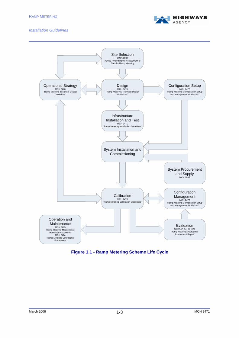
The document is intended to be used as supporting material for ramp metering installation and should be read in conjunction with the other documents referenced in Figure 1.1.

RAMP METERING Installation Guidelines
March 2008 MCH 2471 1-1
1. Introduction
1.1 Ramp Metering Background and Concept
Ramp metering is a traffic management technique, which regulates the number of vehicles allowed to join a motorway at peak periods. The purpose of ramp metering is to prevent or delay the onset of flow breakdown on the main carriageway by a combination of:
♦ Restricting the flow onto the motorway of additional traffic that, if unrestricted, would trigger flow breakdown; and,
♦ Managing the flow on the entry slip road to avoid large platoons of vehicles entering the main carriageway and causing flow breakdown.
By preventing or delaying flow breakdown, the system provides the following benefits:
♦ Less congestion and improved traffic flows; ♦ Greater throughput during peak periods; and, ♦ Smoother and more reliable journey times.
The ramp metering system uses part-time signals on the slip road which come into operation when traffic sensors on the main carriageway indicate heavy traffic. The loops on the mainline along with queue detection loops on the slip road enable the system to determine the required flows from the slip to keep the mainline flowing just below critical occupancy.
1.2 Ramp Metering Deployment
The Highways Agency undertook a project to deliver thirty ramp metering sites located in the West Midlands and the North of England. The thirty sites have been installed in the following Highways Agency MAC Areas.
♦ Area 9: 10 sites; ♦ Area 10: 12 sites; ♦ Area 11: 1 site; and, ♦ Area 12: 7 sites.
These sites are operational and show varying benefits. This document builds on the lessons learnt during the installation of these thirty sites to give a guideline to the key areas of installing a ramp metering site.
1.3 Ramp Metering Scheme Overview
A typical ramp metering scheme can be split into sections as detailed in Figure 1.1. Each section can be defined individually but aspects from each will overlap and impact on the next. The Contractor shall be aware of the ramp metering scheme life

RAMP METERING Installation Guidelines
March 2008 MCH 2471 1-2
cycle and the impact of these on the installation process. Below is a brief description of each of the sections.
1.3.1 Site selection
This is primarily based on the traffic flows in and around each junction, with considerations being made to junction layout and topography. This can be initiated by a Highways Agency Area team looking for a solution to a particular congestion problem or a major ramp metering implementation scheme. The site selection will produce an output specifying a junction or junctions which may be suitable for ramp metering.
1.3.2 Operational Strategy
This section of the scheme should involve inputs from the site selection, design and calibration teams to formulate an operational strategy for the site. This should include, determining the cause of flow breakdown, slip road flow rates and taking into account the slip road layout. From this information the design and calibration teams will be able to target their work towards giving the greatest possible benefits to the conditions at that particular site.
1.3.3 Design
The underlying principle behind any design is the operational strategy. This is an agreed course of action that the ramp metering project team pursue in order to tackle a specific traffic congestion problem in a pre-determined way.
The Designer has responsibility for developing the design intent and ensuring that the system components can be built and operated in a safe, efficient and cost effective manner.
1.3.4 System Configuration
As part of the design process the Designer shall set up the initial software configuration for the site. This configuration file contains all the site specific settings to allow the system to operate at that junction. Details such as MIDAS selected sites, ramp loops, passwords and access levels are to be setup during this phase.
RAMP METERING Installation Guidelines
March 2008 MCH 2471 1-3
Site SelectionIAN 103/08
Advice Regarding the Assessment of Sites for Ramp Metering
DesignMCH 2470
‘Ramp Metering Technical Design Guidelines’
Infrastructure Installation and Test
MCH 2471 ‘Ramp Metering Installation Guidelines’
System Installation and Commissioning
Evaluation5053147_04_02_027
‘Ramp Metering Operational Assessment Report’
Configuration Management
MCH 2472 ‘Ramp Metering Configuration Setup
and Management Guidelines’
CalibrationMCH 2473
‘Ramp Metering Calibration Guidelines’
Configuration SetupMCH 2472
‘Ramp Metering Configuration Setup and Management Guidelines’
System Procurement and Supply
MCH 1965
Operational StrategyMCH 2470
‘Ramp Metering Technical Design Guidelines’
Operation and Maintenance
MCH 2475‘Ramp Metering Maintenance
Handover Procedures’MCH 2474
‘Ramp Metering Operational Procedures’
Figure 1.1 - Ramp Metering Scheme Life Cycle

RAMP METERING Installation Guidelines
March 2008 MCH 2471 1-4
1.3.5 Installation and Test
This phase of the works includes the installation and test of the infrastructure required for the system. At the end of this phase of the works the site should be ready for the system supplier to install. The installation stage is detailed further in this document
1.3.6 System Installation and Commissioning
Typically the responsibility of the system supplier, this phase of the works includes the installation and commissioning of the ramp metering system equipment including RMCO signal cables and heads. Prior to commissioning the configuration file is loaded onto the system to enable full testing. At the end of this phase of the works the site should be able to operate using the default configuration values loaded to enable commissioning, but not metering traffic as this requires careful setup.
1.3.7 Calibration
During this phase the system is finely tuned to give maximum benefits. This is a balance between slip road delays, queue length and mainline journey time reduction. From the operational strategy generated during the design phase, values for the numerous parameters are derived to give an initial setup. This is then finely tuned whilst the system is live and metering traffic. At the end of this phase the system will be fully operational.
1.3.8 Operation and Maintenance
As the ramp metering system is designed as a stand alone system the operational impacts are negligible. The ramp metering system will adapt to normal changes in traffic flows during summer and winter, activating automatically only when the mainline conditions require.
1.3.9 Evaluation
The detailed setup at each site should be evaluated to ensure it is giving the optimum benefits available. Continuous evaluation and re-calibration may be required if the traffic flows around the area of a particular junction change. This could be due to a Highways Agency scheme in the vicinity of the junction or increased traffic on the slip road due to changes in the local road network.
1.4 Scope of Document
This document gives an insight to the installation procedure and guidance for installation of the system specific aspects of a ramp metering installation.

RAMP METERING Installation Guidelines
March 2008 MCH 2471 1-5
1.5 Document Structure
Section 1 is a basic introduction to the document.
Section 2 includes an overview of the key stakeholders and their responsibilities during the installation of the ramp metering system.
Section 3 details the specific processes to be followed during the installation and planning phase of the works.
Section 4 highlights specific clauses and amendments from the ‘Specification for Highway Works (SHW)’.
Section 5 provides an insight to actions to be taken in case of any changes on site during installation works.
Section 6 details the testing requirements that follow installation
Section 7 provides information on quality management requirements
Section 8 includes a list of ramp metering specific drawings
Section 9 summarises the installation phase and steps into the next phase of ramp metering.
1.6 Related Documents
Background on ramp metering and a more detailed technical specification can be found in the following documents:
♦ MCH1965 ‘Ramp Metering System Requirements Specification’. ♦ Site Selection – Interim Advice Note 103/08. ♦ Ramp Metering Technical Design Guideline -MCH 2470. ♦ Ramp Metering Configuration Setup and Management – MCH 2472. ♦ Ramp Metering Calibration Guideline - MCH 2473. ♦ Ramp Metering Maintenance Handover Procedures – MCH 2474. ♦ Ramp Metering Operational Procedures – MCH 2475.
This document is to be followed in conjunction with the associated sections of the Design Manual for Roads and Bridges (DMRB) and the Specification for Highway Works (SHW).
1.7 Document Limitations
This document is aimed as a guideline for the ramp metering specific aspects of the installation of a ramp metering site. This document does not take into account the specific stakeholders and their contractual arrangements. The information contained in this document is generic in form and the Contractor is to follow the designs provided for their scheme.

RAMP METERING Installation Guidelines
March 2008 MCH 2471 2-6
2. Key Stakeholders
2.1 Introduction
There are several stakeholders involved with the installation of the ramp metering systems. The level of involvement of each party varies and covers a range of aspects such as site selection, design, construction, calibration etc. The following sections outline each of the stakeholders overall roles and responsibilities from experiences gained from previous ramp metering projects.
2.2 Highways Agency
The Highways Agency’s national Traffic Operations (TO) and Standards and Safety Research (SSR) directorates both have key interests in the system. SSR were responsible for designing, procuring and evaluating the earlier schemes. Through the local contract with the TechMAC & MAC, the TO Areas were responsible for the construction of the initial sites and ensuring that the ramp metering systems operate as needed and provide benefits to the Area network. The Regional Control Centres (RCCs) also falls within TO and they will play a role in ensuring network performance, of which ramp metering involvement is a small aspect.
The Highways Agency is the ‘Overseeing Organisation’ under the terms of some installation contracts. The Agency may delegate this authority representative.
2.3 Local Authority
The local authority shall be informed of the scheme works, traffic management measures and timelines. Close liaison with local authority may be required to identify additional requirements that are site specific during the design, installation and configuration phases of ramp metering. The requirement to liaise with the local authority will be necessary for any sites employing integrated traffic management in future.
2.4 Designer
The Designer shall liaise with other stakeholders and be responsible for developing the design to address specific traffic congestion problems. The Designer shall liaise with other ramp metering teams from the operational strategy stage thereby ensuring that the ramp metering design can be installed, operated and maintained safely, efficiently and in a cost effective.
2.5 The Contractor
The Contractor is responsible for installation and testing of the infrastructure and associated cabling. Detailed requirements for the installation works are to be provided by the Designer. Typically the Contractor assumes the role of Principal Contractor and is responsible for the health and safety aspects of the site works.

RAMP METERING Installation Guidelines
March 2008 MCH 2471 2-7
2.6 System Suppliers
The contract to provide and install the ramp metering system equipment was let to IPL, with Peek acting as their subcontractor. IPL/Peek currently operates a maintenance contract with the Highways Agency to cover the aspects of the ramp metering system which they have supplied and installed. This includes the hardware and software for the signal heads, the ramp metering controller, and the associated cabling.
2.7 National Roads Telecommunications Service (NRTS)
At a national level, NRTS took responsibility for the Highways Agency’s communications network during early 2007 (actual dates were Area-dependant). For this reason, NRTS had limited involvement in the initial thirty sites however NRTS will be responsible for the provision of the communications aspects of future ramp metering installations.
There are two main services NRTS are required to deliver (several remote communications setups are possible) across the ramp metering sites such as:
♦ Communications link to the internet to allow remote monitoring, fault handling and maintenance; and,
♦ Communications link to the main carriageway’s Midas outstations. (This link is referred to as the OAL link).
NRTS will influence the type of equipment procured and the techniques used to provide communications links of future sites. NRTS processes are to be followed with early involvement required to determine Service Delivery Points (SDP’s).
2.8 CDM Coordinator
The CDM Coordinator shall be appointed by the Client at the design stage itself. The CDM Coordinator shall typically produce the F10 notification where required. The CDM Coordinator shall advise on health and safety issues during the design and planning phases of installation works.
2.9 Maintainer
The ramp metering system involves several technical aspects and is covered by different maintainers. The maintainers involved with ramp metering are NRTS (National Roads Telecommunications Services), TechMAC, MAC and Peek. The responsibilities of the maintainer are detailed in the ‘Maintenance Procedures’ document (document reference. MCH 2475).

RAMP METERING Installation Guidelines
March 2008 MCH 2471 3-8
3. Installation Procedure
3.1 Introduction
The specific installation programme is to be determined by the Contractor to reflect the stages of design but the following section gives a general overview of ramp metering specific aspects and the timescales involved.
3.2 Pre Installation Works
3.2.1 Temporary Traffic Regulation Order (TTRO)
Due to the nature of the system requiring the provision of loops on the slip road a TTRO will be required. This is to allow for safe working conditions during the installation of the slip road loops, anti skid and white lining, including the stop line. A slip road closure, with associated diversion route, will be required on several occasions during the scheme for:
♦ Installation of the slip road loops; ♦ Installation of the anti skid surfacing; ♦ Installation of white lines including stop line; ♦ Installation of signal poles and heads; and, ♦ If required, remove bags over signal heads. The Highways Agency area specific road space booking procedures are to be followed but typically this needs to be done 12 to 14 weeks prior to the closure.
3.2.2 NRTS
The NRTS SDP need to be defined early in the installation process, these are:
♦ OAL link.
Service Delivery Point1 (SDP1) is at the Lightning Protection Unit (LPU) in the MIDAS outstation. SDP2 is at Terminal Block Cabinet (TBC2) in the RMC cabinet. This typically uses the existing longitudinal cables to link the RMC to the MIDAS outstations. To complete this link new quad cable will be required between the RMC and the longitudinal cables and also from the longitudinal cables to the Midas outstations.
♦ Remote communications link.
Service delivery point is at the ethernet port at the output of the NRTS equipment. The network cable between the NRTS equipment and the RMC is to be provided by the Contractor.

RAMP METERING Installation Guidelines
March 2008 MCH 2471 3-9
Standard NRTS processes and timescales apply to the provisioning of these Service Types and SDP’s. This requires approximately 12 weeks for a process request and a further 12 weeks for provision of the circuits.
3.2.3 Geotechnical and Environmental
Standard Highways Agency requirements for geotechnical and environmental surveys are to be followed; if any site specific approvals are required a minimum of 16 weeks shall be allowed.
3.2.4 Power
If the installation requires a new electricity supply, guidance shall be sought early on the programme from the local service providers to determine timescales and any need for way leaves.
3.3 Installation
The installation works includes, but is not limited to:
♦ Slip road loops; ♦ Cabinets; ♦ Ducts; ♦ Chambers; ♦ Safety barrier; ♦ Anti-skid; ♦ Associated warning signs; and, ♦ Local cabling.
Typically if there are no requirements for retaining walls or other complex structures the installation of the associated infrastructure will follow standard procedures for Highways Agency communications schemes and take approximately four to six weeks.
All of the infrastructure will be located at a defined distance from the stop line. Whilst it is not recommended to install the stop line across the slip road without a working set of traffic signals, this position needs to be determined prior to the rest of the infrastructure. Once the stop line position is marked out, the positions of the slip road loops, signal heads, chambers and cabinets can be confirmed.
It is recommended that the chambers for the slip road loops are installed prior to loop cutting to reduce the risk of damage to unprotected loop tails during construction.
It is the responsibility of the system supplier to provide the signal heads and associated wiring. If the design requires passive poles the infrastructure Contractor is to provide the signal poles. It is recommended that the signal heads are built onto the

RAMP METERING Installation Guidelines
March 2008 MCH 2471 3-10
poles before installation onto site; this reduces any health and safety risks associated with working at height.
3.4 Additional Requirements
3.4.1 OAL Testing
Prior to the installation of the RMC equipment the Contractor shall test the OAL circuit to ensure full functionality. It has been found that the MIDAS Outstation Test Equipment (MOTE) can test the link using the ’scan and transponder simulation’ functions. Whilst the MOTE is not currently setup to fully test the OAL ports of a MIDAS outstation these tests give and indication as to the health of the link.
3.4.2 System Installation and Commissioning
The system supplier will install the RMC equipment and cabling into the cabinets and chambers provided after the main infrastructure works is complete. The Contractor is required to provide traffic management for this works. A fully ducted network is required between the RMC cabinet and the signal poles to enable cabling after the main infrastructure works is complete.
The system supplier is responsible for the commissioning of the ramp metering system and this is to be witnessed by the Overseeing Organisation.
3.4.3 Ramp metering outstation information cards
Partially completed ramp metering outstation information cards will be supplied by the Designer. The installation aspects of this need to be completed and the cards laminated and installed in the RMC cabinets. Further details can be found in the document ‘Ramp Metering Configuration Set-up and Management’ (document reference. MCH 2472).

RAMP METERING Installation Guidelines
March 2008 MCH 2471 4-11
4. Specification for Highway Works Amendments
4.1 Introduction
The following section includes a generic overview of the additions to the Specification for Highway Works (SHW) that are required for installing ramp metering systems. This will give an indication of the ramp metering specific requirements during the installation phase of the works.
The details in this section are not intended to be used as a contract for future installations. Care is to be taken to ensure the use of the latest specifications at the time of design and installation as these may differ from those listed below.
Any specific materials and part numbers detailed below refer to the design produced for initial sites. Contractors are to follow the site specific design provided for their installation.
4.2 Preliminaries
4.2.1 Appendix 1/1: General Requirements
Typically a period of six weeks shall be allowed in the programme following completion of the last ramp metering site installed as part of the scheme for installation and commissioning of the ramp metering control system by the system supplier. NRTS timelines shall be taken into consideration.
The Contractor shall be responsible for co-ordinating these works in close liaison with the Designer and the systems supplier. Responsibility for the installation and commissioning of ramp metering control equipment remains with the system supplier and Designer.
The Contractor shall remain as Principal Contractor throughout this installation and commissioning period and shall provide traffic management as required for the systems supplier and the Designer.
The Contractor shall be responsible for obtaining all necessary agreements from utility services companies and authorities necessary to enable compliance with the contract requirements in areas of the site where their services are located.
The systems supplier shall require a hard shoulder closure for three separate days at each site.
4.2.2 Appendix 1/7: Site Extent and Limitations on Use
The Contractor shall comply in accordance with the requirements of this clause.

RAMP METERING Installation Guidelines
March 2008 MCH 2471 4-12
4.2.3 Appendix 1/11: Structural Elements and Other Features to be designed
Passively safe post foundations shall be in accordance with manufacturer’s recommendations.
4.2.4 Appendix 1/17: Traffic Safety and Management
Traffic Management Programme
When temporary traffic orders are required for proposals put forward by the Contractor, a draft shall be submitted, allowing adequate notice periods for approval.
The Contractor shall co-ordinate and liaise with all other parties working on the network in order to programme the works. A temporary traffic regulation order shall be approved by the Highways Agency with details passed on to the local police. Temporary traffic management shall be as detailed in Chapter 8. Only one temporary traffic management layout shall be permitted at any one time. Recovery vehicles will not be provided. Off peak traffic management shall be used as required. Access through the site for emergency service vehicles shall be maintained at all times.
4.2.5 Appendix 1/18: Temporary Diversions for Traffic
Temporary diversions shall be required for loop installations on the slip roads and for cross slip open cut trenches. Temporary diversions shall be required for white lining renewal on the slip roads.
4.2.6 Appendix 1/24: Quality Management System
The Contractor shall comply in accordance with the requirements of this clause.
4.2.7 Appendix 1/72: Temporary Works
The Contractor shall comply in accordance with the requirements of this clause.
4.2.8 Appendix 1/73: Equipment to be designed by the Contractor
The Contractor shall comply in accordance with the requirements of this clause.

RAMP METERING Installation Guidelines
March 2008 MCH 2471 4-13
4.3 Fencing and Environmental Barriers
4.3.1 Appendix 3/1: Fencing, Gates and Stiles
The Contractor shall carry out modifications to the motorway boundary fence in accordance with MCX0146 and 0153 series drawings to facilitate installation of new type 609 cabinets if any required.
4.4 Safety Fences, Safety Barriers and Pedestrian Guard Rails
4.4.1 Appendix 4/1: Road Restraint Systems (Vehicles & Pedestrian)
The Contractor shall comply in accordance with the requirements of this clause.
4.4.2 Appendix 4/2: Compliance of Road Restraint Systems
The Contractor shall submit supporting information demonstrating compliance with BS EN1317-1, BS EN1317-2, BS EN1317-3 and DD ENV1317-4:2002 for acceptance: European Committee for Standardisation (CEN) Compliance1.
Typical requirements at any ramp metering site include provision of safety fence system (class N2, W4) in accordance with TD19/06 at Electricity Interface cabinet site and the RMC site.
4.5 Road Pavements - General
4.5.1 Appendix 7/1: Road pavements
For a typical ramp metering site, high friction surfacing is required for 39m from start of slip to the queue override loops then 50m on approach to the signal heads near the stop line.
Condition surveys of the slip road are necessary to determine whether any remedial action is required prior to cutting loops and also determine whether any existing high friction surface is present. Any remedial work required to be carried out shall be taken up in agreement with MAC.
Where there is a requirement to extend existing high friction surfacing the new surfacing shall match the existing surface in colour.
4.5.2 Appendix 7/2: Permitted Pavement Options
Pavement shall comply in accordance with the SHW, Series 700.
The permitted construction material for pavement layer shall be high friction surfacing. Typical requirements for pavements in a ramp metering site are given in Table 4.1 and 4.2.

RAMP METERING Installation Guidelines
March 2008 MCH 2471 4-14
Typical Requirements – All Sections
Grid for checking surface levels (Clause 702.4)
Longitudinal dimension
Transverse dimension
10m
2m
Surface regularity (Clause 702.5) Category of Road A
Interval for measurement of surface regularity (Clause 702.7)
In each wheel track 300m
Interval for measurement of transverse regularity (Clause 702.8)
In each wheel track 20m
Area without high friction surfacing Yes Whether surface texture is required(Clause 921.2)
Area with high friction surfacing No
Table 4.1 - Typical Requirements for Construction Materials
Material Reference
SHW Clause
Description Requirement
HFS 924 High Friction Surfacing
Calcined bauxite with epoxy binder
BBA/HAPAS Classification (Table NG9/24): Type 1
Minimum PSV: 70+
Max AAV: 5
Guarantee Period: 2 years
Table 4.2 - Typical Requirements for Construction Materials
Care shall be taken regarding the compatibility of the selected Clause 924 high friction surfacing material with that of the newly laid or existing carriageway construction.
4.5.3 Appendix 7/2: Excavation, Repair and Reinstatement of Existing Surfaces
The Contractor shall comply in accordance with the requirements of this clause.
RAMP METERING Installation Guidelines
March 2008 MCH 2471 4-15
4.6 Kerbs, Footways and Paved Areas
4.6.1 Appendix 11/1: Kerbs, Footways and Paved Areas
Footways and handrails are required at cabinet site locations.
Access steps shall be provided to suit local topography at cabinet site locations.
The Contractor shall provide and install footways between the hard shoulder and the cabinet sites. Footways to cabinets should be detailed by the Contractor in his design proposals for these locations.
Kerbs, footways and paved areas for typical RM sites include pathways in verge at a length not exceeding 5 meters and access steps with a typical gradient of 1:2 for a slope length not exceeding 5 meters.
4.6.2 Appendix 11/2: Access Steps
The Contractor shall comply in accordance with the requirements of this clause.
4.7 Traffic Signs
4.7.1 Appendix 12/1: Traffic Signs
The design drawings shall indicate the detailed locations of any traffic signs that are required.
In order to avoid specula reflection from the sign faces, signs which are approached along a straight length of road shall be set at an angle of 95° measured clockwise from the nearside edge of the carriageway.
The issued sign lighting drawing, provides details of:
♦ Sign lighting illumination and switching requirements (lamp type and wattage); ♦ Sign lighting cable length and trenching requirements; and, ♦ Sign lighting power source.
All plate signs shall be sheet aluminium as described in BS 873 with a minimum thickness of 3mm. Where reflective material is required it shall have a photometric performance complying with the requirements of BS 873, Part 6.
Earthing shall be in accordance with BS 7671.
Sign Erection
When the erection of the sign is complete, all slip-sheets and tapes shall be removed and the sign left in a clean condition. If it is necessary to wash the sign this shall be carried out with materials approved by the sign manufacturer.

RAMP METERING Installation Guidelines
March 2008 MCH 2471 4-16
Upon completion and servicing of the signs, they shall be thoroughly cleaned immediately prior to hand over.
Where standard tubular steel posts are required for supporting traffic signs they shall be welded posts and comply with the requirements of BS 873.
All passively safe posts shall be non energy absorbing category NE and speed class 100 kph in accordance with BS EN 12767. Passively safe posts may satisfy any of the four occupant safety levels specified in Table 3 of BS EN 12767.
Where signs are mounted on passive sign posts, the minimum mounting height shall typically be 1800 mm.
For passively safe structures disconnect cables shall be provided in accordance with manufacturers requirements that remove an IP68 rated plug from its socket in the event of a road traffic collision. These cables require clamping both in the post and the adjacent chamber to prevent excess cable being pulled through in the event of collision. Type ‘C’ chambers or similarly equivalent shall be provided adjacent to the fixed sign poles to house the joint between the disconnection cable and the cable for signal heads. Labels for chambers installed for passive poles shall be detailed in Appendix 15/2.
A tolerance of +100mm and -00mm is applicable to the vertical clearance to the sign plate, and a tolerance of +100mm to the lateral clearance.
Compartments for Electrical Equipment
For illuminated signs the electrical equipment shall be enclosed in an integral base housing. The central access opening shall face away from the carriageway and entry to the interior of such compartments shall be by means of a weatherproof door having tamper-resistant key fastenings of a type acceptable to the local highway authority. An internal baseboard manufactured from substantially non-hygroscopic and rot-resistant material shall be fixed in the box and an earthing screw or bolt to be provided.
4.7.2 Appendix 12/3: Traffic Signs - Road Markings and Studs
New lane markings, carriageway edge lines and stop lines are to be applied along the length of the slip road. The stop line shall not be installed until the night before the system is made operational.
The stop line is to extend the full width of the carriageway including hard shoulder.
4.7.3 Appendix 12/5: Traffic Signals
Typically the signal heads shall be installed in the verges 2m downstream of the stop-line position.
All poles shall be passively safe poles and be non energy absorbing category NE and speed class 100 kph in accordance with BS EN 12767. Passively safe poles may

RAMP METERING Installation Guidelines
March 2008 MCH 2471 4-17
satisfy any of the four occupant safety levels specified in Table 3 of BS EN 12767. For passively safe structures additional electrical cut-outs and clamping arrangements, as detailed in TA89/05, shall be provided and installed in accordance with manufacturers’ requirements to remove an IP68 plug from its socket in the event of a road traffic collision. The minimum length of cable connected to the plug shall typically be 4m.
Poles for mounting the signal heads shall be Jerol 219mm diameter passively safe poles. These poles shall be 6.5m high from ground level.
Type ‘C’ chambers or similarly equivalent shall be provided adjacent to the traffic signal poles to house the joint between the disconnection cable and the signal head cable. The IP68 joint shall be Poletech part number MOULDENCLOS120X200ORA16 or suitably appropriate equivalent. The joint shall be suitable for termination of the 16-core disconnect cable together with a 12-core and a 4-core traffic signal cable. Agreement shall be sought with the Designer where alternative joints are to be used.
The Contractor shall arrange for the signal poles to be pre-drilled by the manufacturer for 2 signals on each post, one at standard upper level and one with the lower mounting bracket at typically 1.8m (at motorist eye level).
The signal poles shall be pre-drilled to enable the installation of a junction box that provides the joint between the disconnection cable and the cables to the signal heads. Care shall be taken to ensure cables and signal heads can be easily aligned and installed.
Signal poles are to have an identification label fitted similar to those used for post mounted signals detailed on MCX 0145. Labels shall be laminated sheet, and not the adhesive type, secured with banding around the pole.
Installation of the signal poles is the responsibility of the Contractor; however the Contractor shall liaise with the ramp metering system supplier so that signal heads, junction boxes and disconnect cabling can be assembled onto the poles prior to installation.
The Contractor shall be responsible for safely transporting, loading and unloading the poles and attached equipment at all times. The system supplier shall attend site when the assembled poles are to be installed to provide advice and to align the upper and lower signal heads. The system supplier shall perform a confidence check of the installed signals at this visit.
The Contractor shall ensure that the system supplier aligns the lower signal heads to allow visibility for the driver at the stop line.
The system supplier will provide the junction boxes that are to be fitted to the pole.
The signal heads are to be bagged by the system supplier prior to being installed on site. Bags shall be removed only on the night before the system is made live.

RAMP METERING Installation Guidelines
March 2008 MCH 2471 4-18
The following are the installation requirements for signals and signs for a typical ramp metering site:
♦ Supply and installation of 750 triangle assembly 'Queues likely …' fixed sign; ♦ Supply and installation of 900 triangle 'Traffic Signals …' fixed sign; ♦ Supply and installation of passively safe post for 750 triangle assembly 'Queues
likely …' Fixed Sign (including foundations in accordance with manufacturer’s recommendations);
♦ Supply and installation of standard post suitable for 900 triangle ‘Traffic Signals …’ fixed sign (including foundations in accordance with manufacturer’s recommendations);
♦ Supply of pre-drilled passive poles and IP68 enclosures for signal heads including delivery to systems supplier’s premises;
♦ Installation of passively safe post 6.5m high suitable for mounting signal heads (with low and high level signal heads installed);
♦ Supply and installation of pre-cast foundations for signal head poles; ♦ Collection of complete signal pole assemblies and installation on site; ♦ Removal of bags from signal heads and alignment of lower signal heads; ♦ Reinstatement of existing road markings; ♦ Installation of stop line and white lining on approach to the merge; and, ♦ Supply and installation of break-away plug and cable system suitable for 12 core
signals cable (e.g. POLETECH DOT.PLUG plug/socket assembly 16 pin system).
4.8 Electrical Work for Road Lighting and Traffic Signs
4.8.1 Appendix 14/1: Lighting Site Records
The Contractor shall comply in accordance with the requirements of this clause.
4.8.2 Appendix 14/2: Location of Lighting Units
The Contractor shall comply in accordance with the requirements of this clause.
4.8.3 Appendix 14/3: Temporary Lighting
The Contractor shall comply in accordance with the requirements of this clause.
4.8.4 Appendix 14/4 and 14/5: Electrical Equipment for Sign Lighting and Traffic Signs
The Contractor shall comply in accordance with the requirements of this clause.
Cables and Cable Ducts
Electrical work required for road lighting and traffic signs for a typical ramp metering site include the following:

RAMP METERING Installation Guidelines
March 2008 MCH 2471 4-19
♦ Locating buried road lighting and traffic signs cable in verges, embankments and cuttings;
♦ Trench for armoured cable in accordance with highways construction details. ♦ Supply and installation of 10mm2 2-core armoured energy cable for street
lighting (with MDPE or XLPE over sheath); ♦ Supply and installation of C type lantern (with 2x 20w MBFU lamps) complete
with miniature photocell and bracket arm for attachment to passive pole for 900mm triangle assembly (including terminations);
♦ Supply and installation of lighting feeder pillar complete, in accordance with Appendix14/4 and 14/5 and manufacturer’s recommendations;
♦ Supply and installation of sign post cut-outs in accordance with BS 7654 and highway construction details; and,
♦ Armoured cable terminations to be carried out in accordance with highway construction details.
4.9 Motorway Communications
4.9.1 Appendix 15/1: General Requirements
The Contractor shall supply and install all equipment and cables necessary to complete the works that are not listed in the schedule of bulk purchase items. A copy of the submitted MCH 1286 is available from the Designer upon request.
List of equipment and cables necessary to complete the works for a typical RM site are:
♦ Armoured/non-armoured quad cable; ♦ Armoured/non-armoured 10mm² three core energy cable; ♦ Armoured/non-armoured loop feeder cable; ♦ Non-armoured detector loop cable; ♦ Plinth 610 & skirt; ♦ Cabinet 600, PDU & heater and termination frame; ♦ Cabinet 609; and, ♦ Box 615.
Collect from the Overseeing Organisation’s store during opening hours at Howard Terens, Burma Road, Sharpness, Berkeley, GL13 9QU, and load, unload, store and install all cabinets, cables and ancillary items.
Supply, deliver and install all associated cable fittings including brass cable glands for power cables and aluminium glands for communications cables terminated in aluminium boxes.
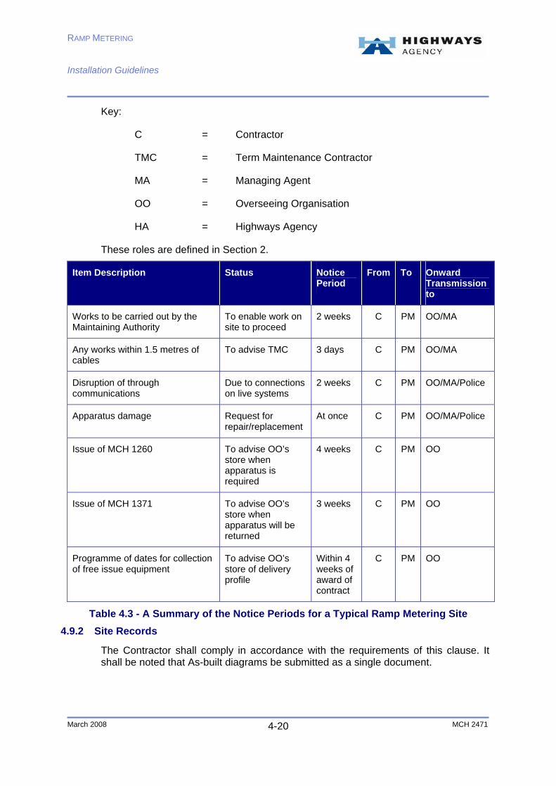
A summary of the notice periods for a typical ramp metering site is shown below in Table 4.3. NRTS timelines shall be taken into account.
RAMP METERING Installation Guidelines
March 2008 MCH 2471 4-20
Key:
C = Contractor
TMC = Term Maintenance Contractor
MA = Managing Agent
OO = Overseeing Organisation
HA = Highways Agency
These roles are defined in Section 2.
Item Description Status Notice Period
From To Onward Transmission to
Works to be carried out by the Maintaining Authority
To enable work on site to proceed
2 weeks C PM OO/MA
Any works within 1.5 metres of cables
To advise TMC 3 days C PM OO/MA
Disruption of through communications
Due to connections on live systems
2 weeks C PM OO/MA/Police
Apparatus damage Request for repair/replacement
At once C PM OO/MA/Police
Issue of MCH 1260 To advise OO’s store when apparatus is required
4 weeks C PM OO
Issue of MCH 1371 To advise OO’s store when apparatus will be returned
3 weeks C PM OO
Programme of dates for collection of free issue equipment
To advise OO’s store of delivery profile
Within 4 weeks of award of contract
C PM OO
Table 4.3 - A Summary of the Notice Periods for a Typical Ramp Metering Site
4.9.2 Site Records
The Contractor shall comply in accordance with the requirements of this clause. It shall be noted that As-built diagrams be submitted as a single document.

RAMP METERING Installation Guidelines
March 2008 MCH 2471 4-21
Provision of Cabinets, Cables and Ancillary Items
The Contractor shall comply in accordance with the requirements of this clause.
Local Cables
Communications cable will be provided by the Overseeing Organisation. Cables shown below are for a typical ramp metering installation work:
♦ Non-armoured copper communications cable to the Highways Agency’s specification TR 2150;
♦ Armoured copper communications cable to the Highways Agency’s specification TR 2158;
♦ Non-armoured/armoured loop feeder cable to the Highways Agency’s specification TR 2031; and
♦ Inductive loop detector cable to the Highways Agency’s specification TR 2029.
Power supply cables provided by the Overseeing Organisation consist of the following:
♦ Non-armoured energy cable, size up to and including 120 mm2 to Highways Agency specification TR 2153; and,
♦ Armoured energy cable, size up to and including 120 mm2 to Highways Agency specification TR 2161.
Cable Installation
The Contractors attention shall be drawn for the need to install additional quad cables between the existing 600 MD cabinets and associated 609C cabinets/CJE.
All cables entering the 600 RMC cabinets shall enter via the adjacent B chamber and associated ducts.
Installation of Cabinets and Signal Posts
Bases for all cabinets shall be sealed in accordance with the Highways Agency HCD series drawings. All cabinets 600 should be sealed with the ducts extending 25mm above the base seal, including those not within ducted networks. Wiring frames for cabinets within ducted networks shall not to be modified and the IDC connection plates are not to be fitted.
Installation of Telephone Posts and Housings
The Contractor shall comply in accordance with the requirements of this clause.
Installation of Items
The Contractor shall provide and install power protection equipment to Highways Agency drawing number MCX 0164 in an Electricity Interface (EI) cabinet type 609 and to MCX 0165 in a rural power cabinet 609. The Contractor shall provide extra supply outlet at EI cabinets in accordance with MCX 0164 arrangement.

RAMP METERING Installation Guidelines
March 2008 MCH 2471 4-22
The Contractor shall be aware of the need for the provision of remote communications. The Contractor shall make all necessary arrangements with NRTS in order to acquire remote communications.
Jointing and Termination of Multi-pair Communications Cables
The Contractor shall terminate the multi-pair communications cables within cabinets 600 and 609 cabinets in accordance with the Highways Agency HCD series of drawings.
The loop cables shall be terminated within the 600 RMC in accordance with scheme standards.
Termination and Jointing of Power Supply Cables for Communications
The Contractor shall comply in accordance with the requirements of this clause.
Earthing, Bonding and Cable Testing
The Contractor shall provide a programme of testing before any testing commences.
The Contractor shall arrange to set up and carry out a confidence check of the OAL (the control circuit from the ramp metering controller to the existing MIDAS outstations). Close liaison with the Designer will be required.
The Contractor shall arrange for NRTS to test the spare pairs available throughout the length of the OAL circuit shown on design drawings and provide survey results.
The pairs to be utilised on the longitudinal cable will be advised by the Highways Agency to the Contractor. The Contractor shall then arrange for the NRTS to terminate the ramp metering quad RMC1 to this pair in the associated CJE (Cable Joint Equipment). The Contractor shall then allow access to carry out the stage 3 test of this circuit. Once this OAL circuit has been set-up and tested as detailed above then the Contractor shall arrange for the Maintainer to connect the additional quads from the existing 600MD’s, installed under these works, to the OAL in the associated type 609 cabinets.
Following completion of the above works the Contractor shall arrange for the Maintainer to perform a functional check on the complete circuit using the MOTE. The Contractor shall confirm with the Designer that the necessary site data change has taken place at the local RCC prior to carrying out this test.
Close liaison with the Designer and the Maintainer will be required throughout this testing period.
Labelling and Numbering
External labels for cabinets shall be in accordance with MCX 0145 except that they shall be manufactured from ‘Traffolyte’ material or equivalent.
The Contractor shall label post 75’s where they are required to be installed. Labels shall be in accordance with MCX 0145, similar to those used on entry stop signals.

RAMP METERING Installation Guidelines
March 2008 MCH 2471 4-23
The provision of labels shall include the provision of warning notices and labels.
The Contractor shall produce a label schedule and submit this schedule for approval.
Labels for chambers installed for passive poles are required as advised in scheme standards.
Loop Detectors
Detector loops shall be installed at the locations indicated on the communications drawings; actual position of loops is to be agreed on site prior to commencing installation. Loops shall be installed and tested in accordance with Highways Agency specification MCH 1540; except each array shall have only one loop, comprising 3 turns, in each of the running lanes unless stated otherwise.
There is no requirement for loops in the hard shoulder.
Only one loop feeder cable shall be used for each loop array with lane 1 being jointed to the red and blue cores of the loop feeder and lane 2 being jointed to the yellow and black cores of the loop feeder.
Presence and release loops have a fixed relationship to the stop line. Closest edge of each loop shall be 2m from stop line.
Modifications to Existing Cabinets
Where additional quads are installed into existing 600MD cabinets in direct buried areas, then these cables shall be terminated to the right-hand side of terminal blocks TBC10 (terminals 11 and 12). Additional looming shall be installed between TBC 6 (terminals 3 and 4) and TBC 10 (terminals 11 and 12) similar to the looming already fitted for the outstation link as detailed on MCX 0594. Cabinet base seals shall be broken out and then re-sealed in accordance with MCX 0156 immediately following installation of cables.
Where additional quads are installed into an existing 609C then these shall be terminated to TBL 9 (terminals 7 and 8) similar to the termination of MIDAS outstation quads as detailed on MCX 0339. The Contractor shall install the link wires from TBL 9 to the transmission side 615 box as detailed on MCX0339.
Where power cables from 600RMC cabinets are to be installed in existing rural 609P cabinets then the Contractor shall modify the existing enclosure to install an additional MK 100A double pole switch as detailed on MCX 0165.
Typical activities involved in ramp metering related motorway communications include:
♦ Chamber specified design group type C with grade B cover and frame depth to uppermost surface of base slab not exceeding 0.6m in accordance with MCX series drawings 0815;
♦ Connection of newly installed 2x100mm transverse ducts into new communications chambers;
RAMP METERING Installation Guidelines
March 2008 MCH 2471 4-24
♦ Motorway communications ducts installed by trench less techniques at nominal depth not less than two meters across two lane and hard shoulder carriageway between verges; and,
♦ Motorway communications ducts installed by trench less techniques at nominal depth not less than two meters across three lane and hard shoulder carriageway between verges.
Typical armoured cable requirements are:
♦ Loop detector feeder (four cores) armoured communications cable supplied by the Overseeing Organisation;
♦ Quad armoured communications cable supplied by the Overseeing Organisation; ♦ 10mm2 three core XLPE/MDPE armoured power cable supplied by the
Overseeing Organisation; ♦ Termination of quad communications armoured cable in cabinet type 609; ♦ Termination of quad communications armoured cable in cabinet type 600; and, ♦ Termination of 10mm2 three core power communications armoured cable to
power protection equipment in 609 type power cabinet.
Typical non-armoured cable requirements are:
♦ Termination of 10mm2 three core power communications non-armoured cable to power protection equipment in 600 type power cabinet;
♦ Termination of four core loop feeder cable in cabinet type 600; and, ♦ Straight joint four core loop feeder cable to loop tail in joint pit.
4.9.3 Appendix 15/2: Cable Ducts
Attention of the Contractor shall be drawn to the compliance requirements of Highways Agency Contractor NRTS with regards to installing ducts, cross carriageway ducts, and chambers for motorway communications cables. Further information is available in the NRTS document ‘PS-DS200-05 v5 SSS Passive CC Ducts and Ducts through Structures’.
Installation of Ducts
Local ducts shall be provided as indicated in the design drawings. The Contractor shall agree the exact location with the Overseeing Organisation before the commencement of any associated ground works.
New duct bungs complete with cable port blanking plugs shall be fitted at all new duct entries to chambers. Where cables are being installed into existing chambers in ducted networks then the Contractor shall remove the blanking plugs from the existing duct bungs and replace with a suitable plug for the type of bung and size of cable being installed.
Ducts shall also be provided at cabinet and chamber sites.

RAMP METERING Installation Guidelines
March 2008 MCH 2471 4-25
Installation of Cable Ducts beneath Motorway
The Contractor shall comply in accordance with the requirements of this clause.
Chambers for Motorway Communications Cables
All covers and frames for new chambers shall comply with BS EN 124. Covers for loop chambers shall be grade D400; all others are to be Grade B125.
Type C chamber adjacent to the signal post shall be installed as close as practicable to the post (typically within 500mm of the foundation).
Type C chambers, adjacent to the fixed sign passively safe posts shall be installed as close as possibly practicable to the post (typically within 500mm of the foundation).
All chambers for passive structures which contain an IP68 joint shall be fitted with a label to indicate the location of the power source for isolation purposes. The label shall uniquely identify the chamber and the source of isolation of the power supply for the associated passive structure.
The Contractor shall connect the existing cross carriageway ducts to the new chambers where required and as indicated in the communications drawings.
The Contractor shall supply four suitable sets of lifting keys for each different type of chamber lid. A suitable cover lifter shall be provided and handed to the Overseeing Organisation for use by the maintaining authority, where the method statement shows they are required to meet health and safety/ CDM requirements.
4.10 Landscape and Ecology
The Contractor shall comply in accordance with the requirements of this clause.
4.10.1 Appendix 30/4: Ground Preparation
The Contractor shall comply in accordance with the requirements of this clause.
RAMP METERING Installation Guidelines
March 2008 MCH 2471 5-26
5. Testing Requirements The Contractor shall comply with the requirements of the SHW (Specification for Highway Works).
Once the OAL circuit has been set-up and the remote MIDAS outstations have been connected as required by the works the Contractor shall arrange for the Maintainer to carry out a functional check of this link using their specialist test equipment (MOTE). The Contractor shall coordinate these works and shall arrange for the Designer to be present during this test.
Ensure that testing of detector loops is in accordance with MCH1540. All ducts shall be tested to confirm correct installation. Proving and testing shall be in accordance with SHW 1533.
Attention of the Contractor shall be drawn to the compliance requirements of Highways Agency Contractor NRTS with regards to Installation Acceptance and test requirements. For further information is detailed in NRTS document ‘GYS/RGD/TSP/0105 ‘Task Authorisation Acceptance Criteria’.

RAMP METERING Installation Guidelines
March 2008 MCH 2471 6-27
6. CDM & Quality Management Requirements All safety, environmental and quality issues shall be managed by the Contractor in accordance with the latest CDM regulations. The MAC for respective Highways Agency areas or the CDM Coordinator shall produce F10 notification where required. A risk register and COSHH assessment for the scheme shall be compiled.

RAMP METERING Installation Guidelines
March 2008 MCH 2471 7-28
7. List of Drawings Drawing No Content
Manual of Contract Documents for Highways Works – Volume 3
Highway Construction Details
Manual of Contract Documents for Highways Works – Volume 3a
Motorway Communications Installation Drawings
5037856_20_01_03_1500 Notes and Legend Sheet
5037856_20_01_03_1503 Traffic Signals Overview
5037856_20_01_03_1506 Foundation Design for Post Mounted Satellite Dish
5037856_20_01_03_03_S0021 Termination Details for RMC Type 600 Cabinet
5037856_20_01_03_03_S0022 Termination Details from RMC Cabinet to Box 615 (Direct Buried)
5037856_20_01_03_03_S0025 Lower Traffic Signal Alignment
5037856_20_01_03_03_S0026 OAL Termination Details with MD 600 Cabinet (Direct Buried Network)
5037856_20_01_03_03_S0027 Road Markings on Approach to Signals
5037856_20_01_03_03_S0031 Passive Post Chamber Label
5037856_20_01_03_1220 Fixed Sign Details
5037856_06_07_012_015 Passive Pole Drilling Requirements
5037856_06_07_11_001 Initial Cable Requirement – Area 10

RAMP METERING Installation Guidelines
March 2008 MCH 2471 8-29
8. Summary With the full design package provided by the Designer and the appropriate contract documents the Contractor can install and test the required infrastructure. Once the infrastructure installation is completed the system supplier shall start the installation, testing and commissioning of the ramp metering system equipment.
The system should not be allowed to meter traffic until detailed calibration is completed.
Further information can be found in the additional documentation listed in section 1.6.
After the system has been installed it must be configured to ensure it provides the intended functionality. Ramp metering sites are normally installed with default configuration values loaded. However, these values are not suitable for controlling traffic.

RAMP METERING Installation Guidelines
March 2008 A-30 MCH 2471
Appendix A: List for SHW Amendments Appendix.
No.
Title
0/1
INTRODUCTION
Contract-specific Additional, Substitute & Cancelled Clauses, Tables and Figures Included in the Contract
0/3 List of Numbered Appendices Referred to in the Specification and included in the Contract
PRELIMINARIES
1/1 General Requirements
1/4 Working and Fabrication Drawings
1/5 Testing to be Carried out by the Contractor
1/7 Site Extent and Limitations on Use
1/9 Control of Noise and Vibration
1/10 Structures to be Designed by the Contractor
1/11 Structural Elements and Other Features to be Designed by the Contractor
1/12 Setting Out and Existing Ground Levels
1/13 Programme of Works
1/16 Privately and Publicly Owned Services and Supplies
1/17 Traffic Safety and Management
1/18 Temporary Diversions for Traffic
1/19 Routeing of Vehicles
1/23 Risks to Health and Safety from Materials or Substances
1/24 Quality Management System
1/72 Temporary Works
1/73 Equipment to be Designed by the Contractor

RAMP METERING Installation Guidelines
March 2008 A-31 MCH 2471
Appendix.
No.
Title
SITE CLEARANCE
2/1 List of Buildings, etc, to be Demolished
2/3 Retention of Material Arising from Site Clearance
2/5 Hazardous Materials
FENCING AND ENVIRONMENTAL BARRIES
3/1 Fencing, Gates and Stiles
ROAD RESTRAINT SYSTEMS (VEHICLE AND PEDESTRIAN)
4/1 Road Restraint Systems (Vehicle and Pedestrian)
4/2 Information Required to Demonstrate Compliance of Road Restraint Systems to BS EN 1317-1, BS EN 1317-2, BS EN 1317-3 and DD ENV 1317-4: 2002
DRAINAGE AND SERVICE DUCTS
5/1 Drainage Requirements
5/2 Service Duct Requirements
5/5 Combined Drainage and Kerb Systems
EARTHWORKS
6/1 Requirements for Acceptability & Testing etc of Earthworks Materials
6/2 Requirements for Dealing with Class U2 Unacceptable Material
6/3 Requirements for Excavation, Deposition, Compaction (Other than Dynamic Compaction) Including excavation and reinstatement of existing surfaces.
6/8 Top soiling, Grass Seeding and Turfing
ROAD PAVEMENTS – GENERAL
7/1 Permitted Pavement Options (Schedules 1, 2, 3, 4 and 5)
7/2 Excavation, Repair and Reinstatement of Existing Surfaces
7/4 Bond Coats, Tack Coats and Other Bituminous Sprays (Sheets 1, 2 and Binder Data Sheet)
7/11 Over band and inlaid crack sealing systems

RAMP METERING Installation Guidelines
March 2008 A-32 MCH 2471
Appendix.
No.
Title
KERBS, FOOTWAYS AND PAVED AREAS
11/1 Kerbs, Footways and Paved Areas
11/2 Access Steps
TRAFFIC SIGNS
12/1 Traffic Signs : General
12/3 Traffic Signs : Road Markings and Studs
12/5 Traffic Signs : Traffic Signals
ELECTRICAL WORK FOR ROAD LIGHTING AND TRAFFIC SIGNS
14/1 Lighting Site Records
14/2 Location of Lighting Units
14/3 Temporary Lighting
14/4&14/5 Electrical Equipment for Sign Lighting and Traffic Signs
MOTORWAY COMMUNICATIONS
15/1 General Requirements – Schedule of Bulk Purchase Equipment
15/2 Cable Ducts
STRUCTURAL CONCRETE
17/1 Concrete - Classification of Mixes
17/3 Concrete - Surface Finishes
17/4 Concrete – General
SPECIAL STRUCTURES
25/1 General
MISCELLANEOUS
26/3 Cored Thermoplastic Node Markers
MISCELLANEOUS
30/1 General
30/2 Weed Control

RAMP METERING Installation Guidelines
March 2008 A-33 MCH 2471
Appendix.
No.
Title
30/4 Ground Preparation
30/5 Grass Seeding, Wildflower Seeding and Turfing
30/10 Maintenance of Established Trees and Shrubs
30/12 Special Ecological Measures


