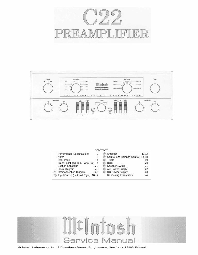
Mclntosh Laboratory, Inc. 2 Chambers Street, Binghamton, New York 13903 Printed CONTENTS Performance Specifications 3 Notes 3 Rear Panel 4 Front Panel and Trim Parts List 4 Section Locations 5-6 Block Diagram 5-6 Interconnection Diagram 6-9 Input/Output (Left and Right) 10-12 Amplifier 11-14 Control and Balance Control 14-18 Treble 19 Bass 20 Speaker Switch 21 AC Power Supply 22 DC Power Supply 23 Repacking Instructions 24
Transcript
Mclntosh Laboratory, Inc. 2 Chambers Street, Binghamton, New York 13903 Printed
CONTENTSPerformance Specifications 3Notes 3Rear Panel 4Front Panel and Trim Parts List 4Section Locations 5-6Block Diagram 5-6Interconnection Diagram 6-9Input/Output (Left and Right) 10-12
Amplifier 11-14Control and Balance Control 14-18Treble 19Bass 20Speaker Switch 21AC Power Supply 22DC Power Supply 23Repacking Instructions 24
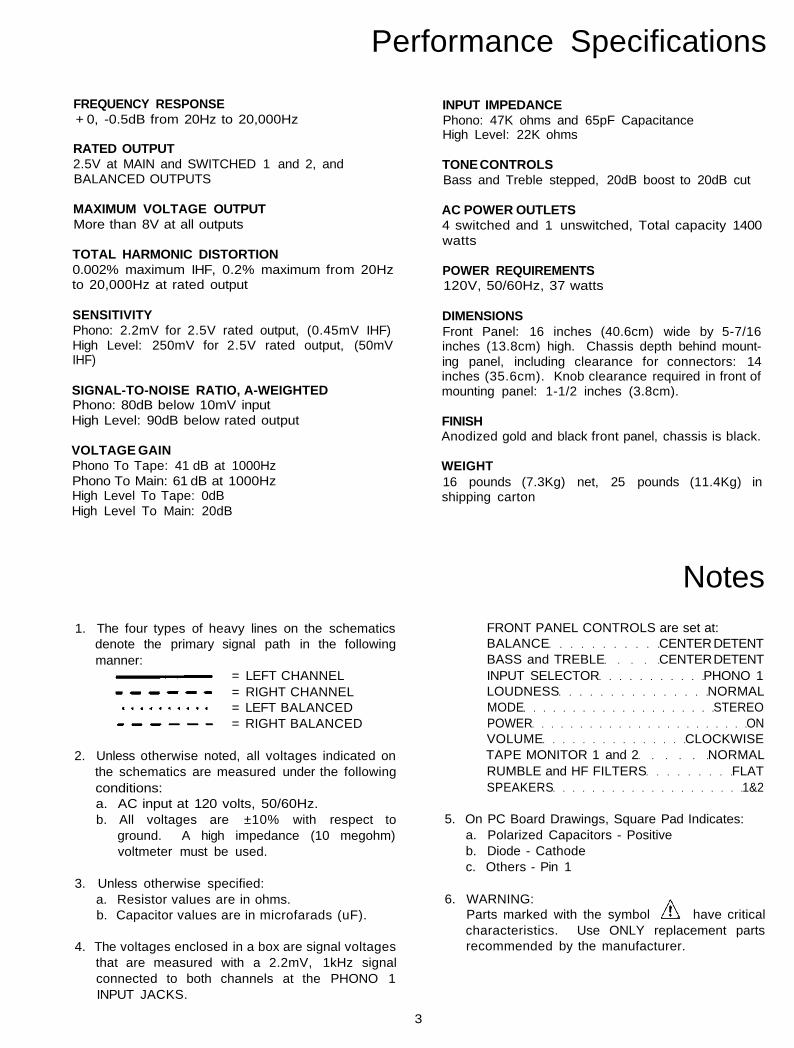
Performance Specifications
FREQUENCY RESPONSE+ 0, -0.5dB from 20Hz to 20,000Hz
RATED OUTPUT2.5V at MAIN and SWITCHED 1 and 2, andBALANCED OUTPUTS
MAXIMUM VOLTAGE OUTPUTMore than 8V at all outputs
TOTAL HARMONIC DISTORTION0.002% maximum IHF, 0.2% maximum from 20Hzto 20,000Hz at rated output
SENSITIVITYPhono: 2.2mV for 2.5V rated output, (0.45mV IHF)High Level: 250mV for 2.5V rated output, (50mVIHF)
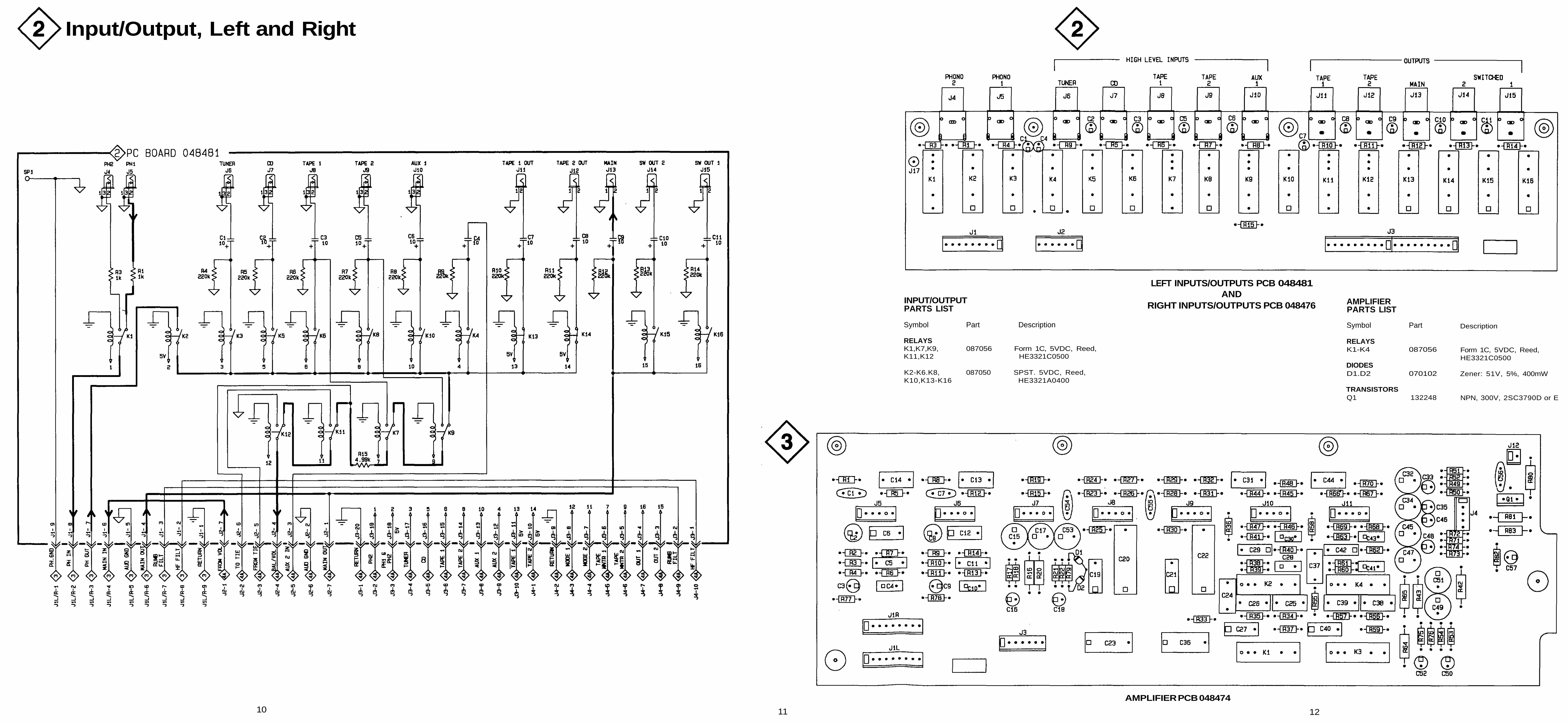
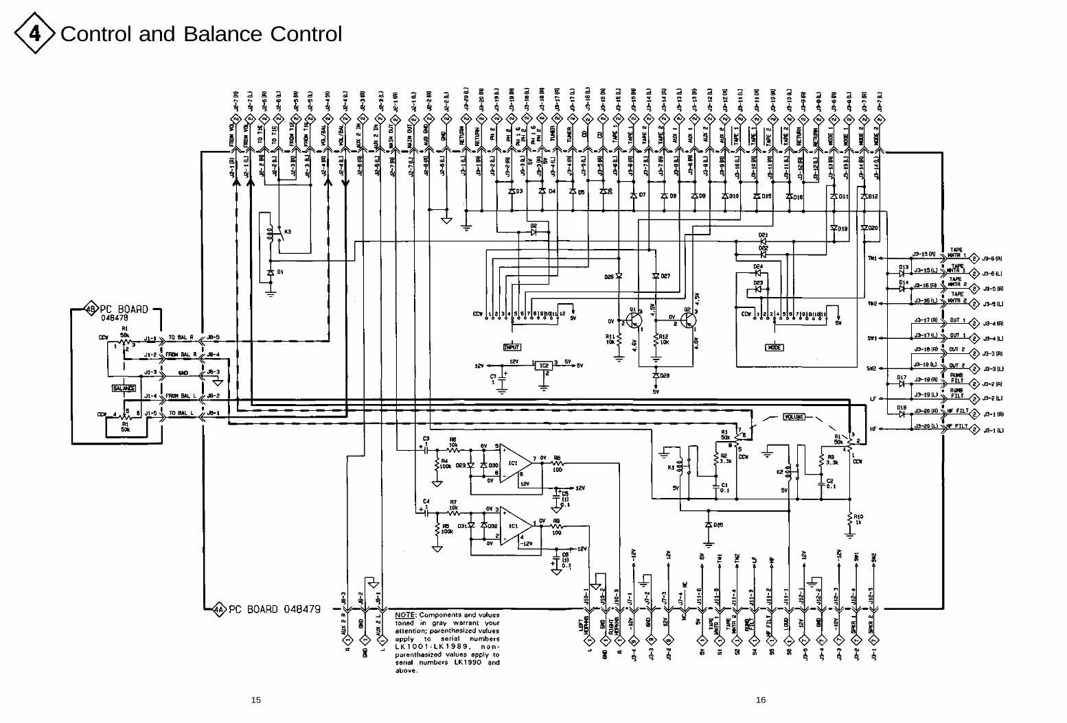
1. The four types of heavy lines on the schematicsdenote the primary signal path in the followingmanner:
= LEFT CHANNEL= RIGHT CHANNEL= LEFT BALANCED= RIGHT BALANCED
2. Unless otherwise noted, all voltages indicated onthe schematics are measured under the followingconditions:a. AC input at 120 volts, 50/60Hz.b. All voltages are ±10% with respect to
ground. A high impedance (10 megohm)voltmeter must be used.
3. Unless otherwise specified:a. Resistor values are in ohms.b. Capacitor values are in microfarads (uF).
4. The voltages enclosed in a box are signal voltagesthat are measured with a 2.2mV, 1kHz signalconnected to both channels at the PHONO 1INPUT JACKS.
FRONT PANEL CONTROLS are set at:BALANCE CENTER DETENTBASS and TREBLE CENTER DETENTINPUT SELECTOR PHONO 1LOUDNESS NORMALMODE STEREOPOWER ONVOLUME CLOCKWISETAPE MONITOR 1 and 2 NORMALRUMBLE and HF FILTERS FLATSPEAKERS 1&2
5. On PC Board Drawings, Square Pad Indicates:a. Polarized Capacitors - Positiveb. Diode - Cathodec. Others - Pin 1
6. WARNING:Parts marked with the symbol have criticalcharacteristics. Use ONLY replacement partsrecommended by the manufacturer.
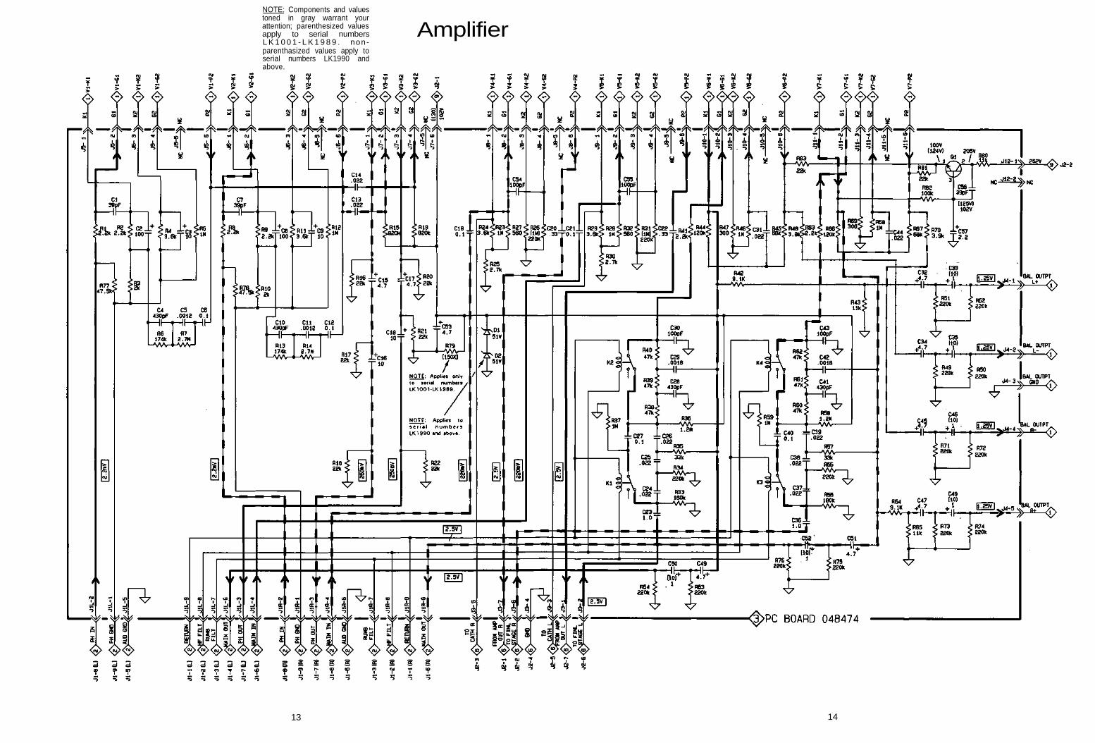
NOTE: Components and valuestoned in gray warrant yourattention; parenthesized valuesapply to serial numbersL K 1 0 0 1 - L K 1 9 8 9 . non-parenthasized values apply toserial numbers LK1990 andabove.
Amplifier
1413
Control and Balance Control
15 16
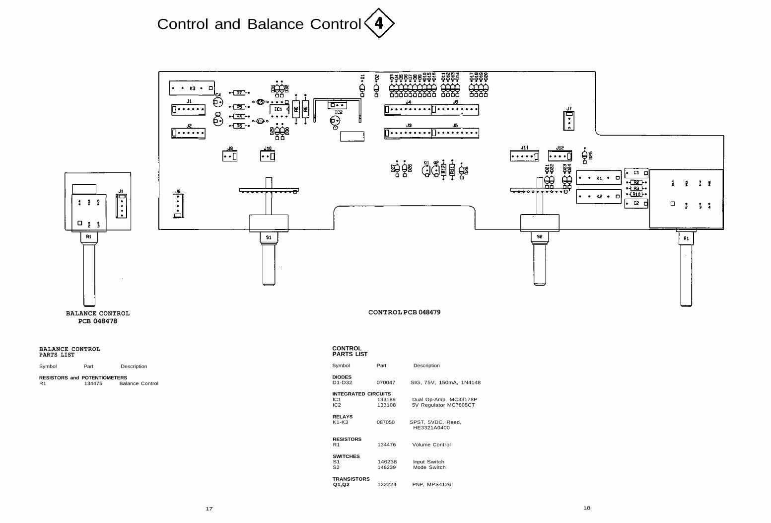
Control and Balance Control
BALANCE CONTROLPCB 048478
CONTROL PCB 048479
BALANCE CONTROLPARTS LIST
Symbol Part Description
RESISTORS and POTENTIOMETERSR1 134475 Balance Control
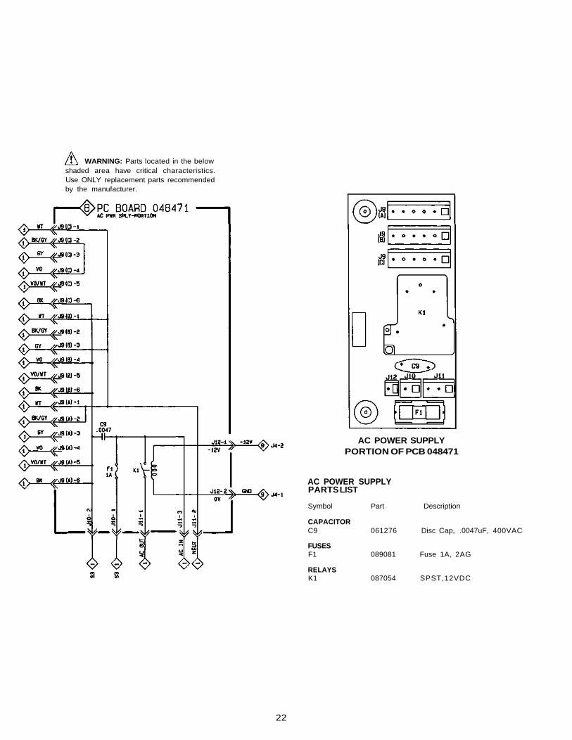
WARNING: Parts located in the belowshaded area have critical characteristics.Use ONLY replacement parts recommendedby the manufacturer.
AC POWER SUPPLYPORTION OF PCB 048471
AC POWER SUPPLYPARTS LIST
Symbol Part Description
CAPACITORC9 061276 Disc Cap, .0047uF, 400VAC
FUSESF1 089081 Fuse 1A, 2AG
RELAYSK1 087054 SPST,12VDC
22
DC Power Supply
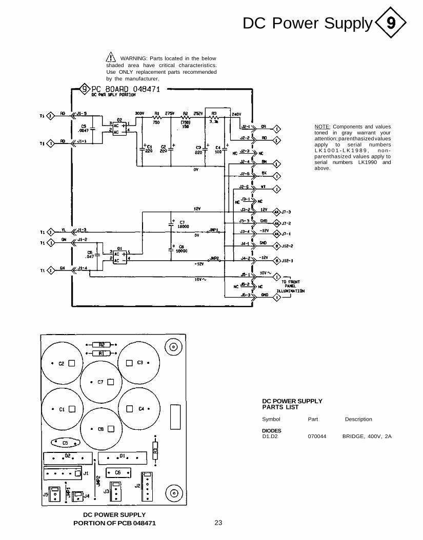
NOTE: Components and valuestoned in gray warrant yourattention; parenthasized valuesapply to serial numbersL K 1 0 0 1 - L K 1 9 8 9 , non-parenthasized values apply toserial numbers LK1990 andabove.
WARNING: Parts located in the belowshaded area have critical characteristics.Use ONLY replacement parts recommendedby the manufacturer.
DC POWER SUPPLYPARTS LIST
Symbol Part Description
DIODESD1.D2 070044 BRIDGE, 400V, 2A
23DC POWER SUPPLY
PORTION OF PCB 048471
Repacking Instructions
In the event it is necessary to repack theunit for shipment, the unit must be packed exactly asshown below.
IMPORTANT - The four plastic feet mustbe attached to the bottom of the unit so they willlocate in the four holes of the bottom pad. Failure todo this will result in shipping damage.
If a shipping carton or any of the interiorparts is needed, please call or write the CustomerService Department of Mclntosh Laboratory. Orderparts from the accompanying list by part number.
Use the original shipping carton and interiorparts only if they are in good serviceable condition.
Qty.
12
111
444
1
Part No. Description
033870 Shipping carton only033884 Corner pad
033883 Inside carton only033885 Top pad033886 Bottom pad
017156 Plastic foot100160 #10-32 x 9/16" Screw104080 #10 Flat washer
033915 Shipping carton completewith all the above parts
INSIDECARTON
BOTTOM PAD
10-32x9/16"SCREW WITHWASHER (4)
BOTTOM COVER
UNIT WITH(4) FEET ON
TOP PADINSIDECARTON
CORNERPAD
SHIPPINGCARTON
C22 PREAMPLIFIER
Part No. 040354BE032003
Printed in U.S.A.Mclntosh Laboratory, Inc., 2 Chambers Street, Binghamton, NY 139O3Telephone (607) 723-3512