36
Mine Countermeasures Vessel (MCMV) Concept Design 23-24 July 2013 1 2013 Summer NREIP Final Presentation
| Date post: | 15-Feb-2017 |
| Category: |
Documents |
| Upload: | brian-weber |
| View: | 362 times |
| Download: | 1 times |

Mine Countermeasures Vessel (MCMV) Concept Design
23-24 July 2013 1 2013 Summer NREIP Final
Presentation

Team Members
Brian Weber Ocean Engineering
Florida Atlantic University
Reid Richardson Ocean Engineering
Florida Atlantic University
Preston Jones High School Student
Pensacola High School
23-24 July 2013 2 2013 Summer NREIP Final
Presentation

Presentation Outline
• Background
• Concept of Operations
• MCMV Vehicles
• Launch & Recovery Systems
• Naval Architecture
• Operational Profile
• Acknowledgements & Conclusion
23-24 July 2013 3 2013 Summer NREIP Final
Presentation
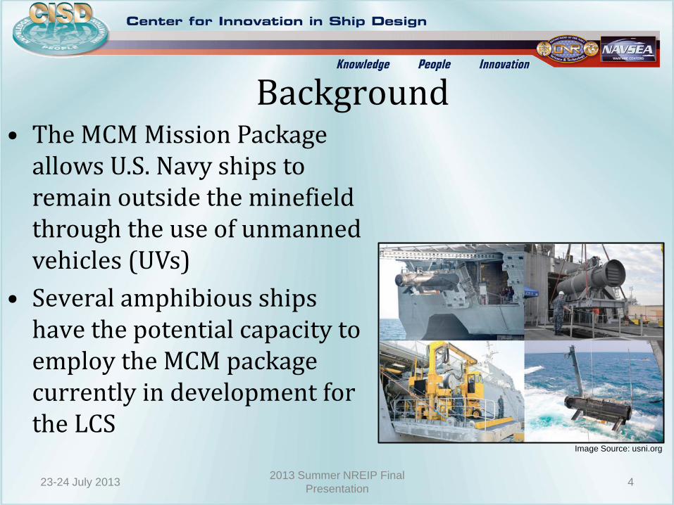
Background • The MCM Mission Package
allows U.S. Navy ships to remain outside the minefield through the use of unmanned vehicles (UVs)
• Several amphibious ships have the potential capacity to employ the MCM package currently in development for the LCS
Image Source: usni.org
23-24 July 2013 4 2013 Summer NREIP Final
Presentation
Task
Integrate a selection of unmanned vehicles onto a self-sufficient Mine Countermeasures Vessel capable of being deployed from an amphibious ship to survey and sweep a minefield
23-24 July 2013 5 2013 Summer NREIP Final
Presentation

Benefits
• Expansion of mission capability for MCM Mission
• Operate in shallow waters
• Reduced vehicle transit time
• Expanded on-station time
• Modular with other vessels of opportunity
• Manned Navy ships can be kept further from mine hazard
• Amphibious ships to perform other missions
• LCS can be utilized for a combatant mission
23-24 July 2013 6 2013 Summer NREIP Final
Presentation
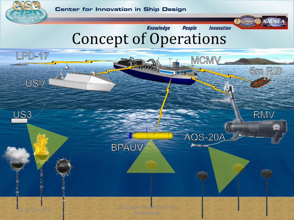
Concept of Operations
23-24 July 2013 7 2013 Summer NREIP Final
Presentation
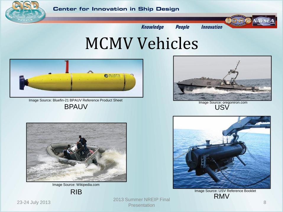
MCMV Vehicles
RIB RMV
USV BPAUV Image Source: Bluefin-21 BPAUV Reference Product Sheet
Image Source: USV Reference Booklet
Image Source: oregoniron.com
Image Source: Wikipedia.com
23-24 July 2013 8 2013 Summer NREIP Final
Presentation
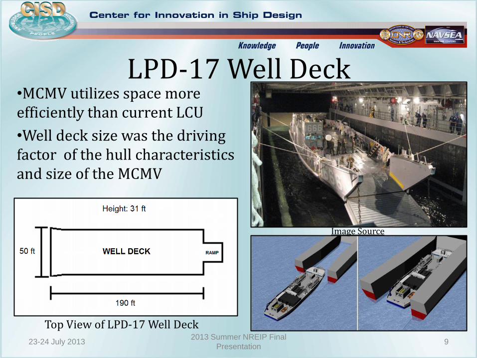
•MCMV utilizes space more efficiently than current LCU
•Well deck size was the driving factor of the hull characteristics and size of the MCMV
LPD-17 Well Deck
Top View of LPD-17 Well Deck
23-24 July 2013 9 2013 Summer NREIP Final
Presentation
Image Source
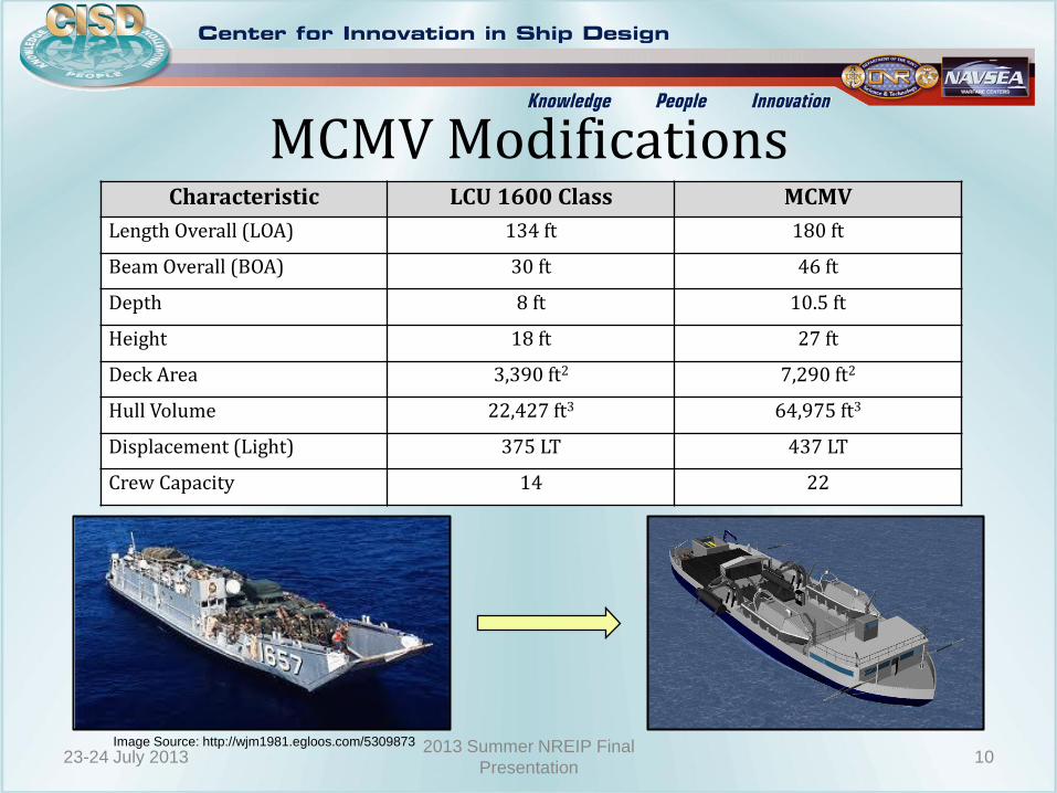
MCMV Modifications Characteristic LCU 1600 Class MCMV
Length Overall (LOA) 134 ft 180 ft
Beam Overall (BOA) 30 ft 46 ft
Depth 8 ft 10.5 ft
Height 18 ft 27 ft
Deck Area 3,390 ft2 7,290 ft2
Hull Volume 22,427 ft3 64,975 ft3
Displacement (Light) 375 LT 437 LT
Crew Capacity 14 22
Image Source: http://wjm1981.egloos.com/5309873
23-24 July 2013 10 2013 Summer NREIP Final
Presentation

Sea-Painter Boom
•Assists in all launch and recovery
•Relieves longitudinal tension
•Telescopic and slewing 23-24 July 2013 11
2013 Summer NREIP Final
Presentation

USV & RMV Launch & Recovery Systems
•Two arm luffing davit
•Telescopic to clear railing and deck
•Storage cradle
•Hydraulic articulating davit
•Rotates on base to store RMV on cradle
23-24 July 2013 12 2013 Summer NREIP Final
Presentation
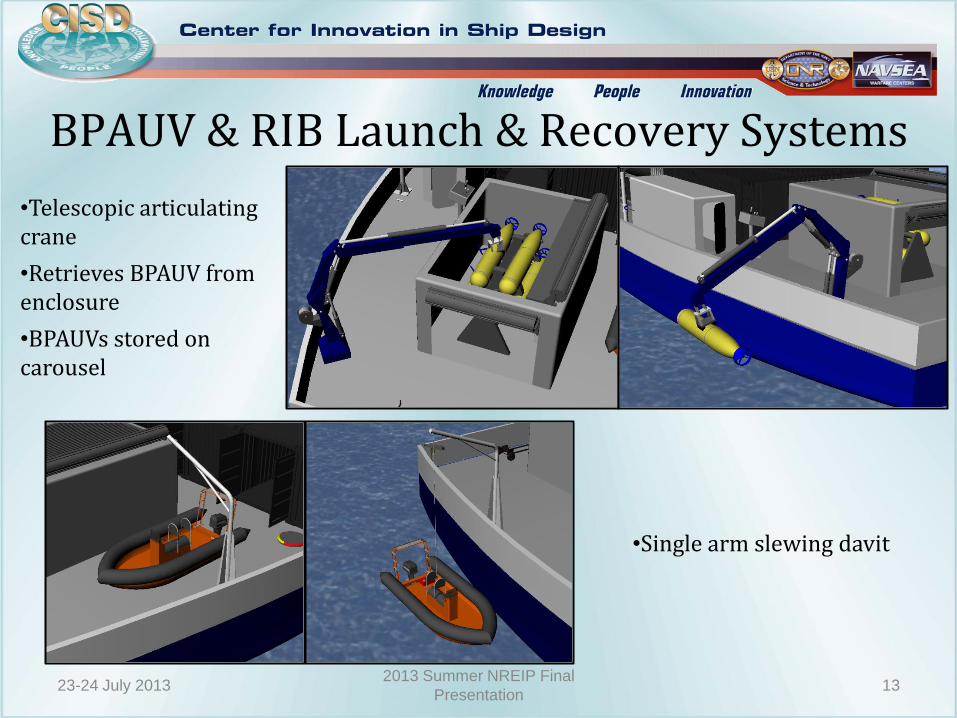
•Telescopic articulating crane
•Retrieves BPAUV from enclosure
•BPAUVs stored on carousel
•Single arm slewing davit
23-24 July 2013 13 2013 Summer NREIP Final
Presentation
BPAUV & RIB Launch & Recovery Systems

Storage & Maintenance
•Retractable enclosure
•Access to ISO from enclosure
•RMV pre/post dive checks require protection from the environment
•Metal retractable doors allow access from top and back side
•Houses BPAUV storage carousel
•Protects sensitive electronics from elements
23-24 July 2013 14 2013 Summer NREIP Final
Presentation
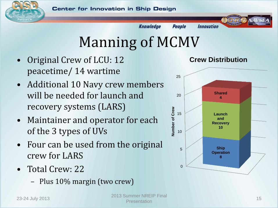
Manning of MCMV • Original Crew of LCU: 12
peacetime/ 14 wartime
• Additional 10 Navy crew members will be needed for launch and recovery systems (LARS)
• Maintainer and operator for each of the 3 types of UVs
• Four can be used from the original crew for LARS
• Total Crew: 22
– Plus 10% margin (two crew)
0
5
10
15
20
25
Ship Operation
8
Launch and
Recovery 10
Shared 4
Nu
mb
er
of
Cre
w
Crew Distribution
23-24 July 2013 15 2013 Summer NREIP Final
Presentation
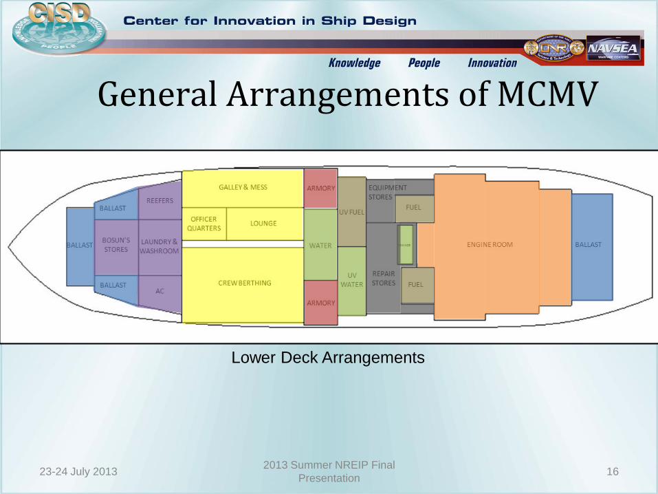
General Arrangements of MCMV
Lower Deck Arrangements
23-24 July 2013 16 2013 Summer NREIP Final
Presentation
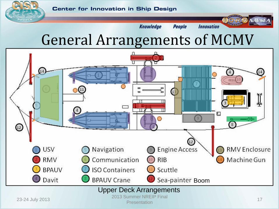
General Arrangements of MCMV
Upper Deck Arrangements
23-24 July 2013 17 2013 Summer NREIP Final
Presentation
Boom

Ship Space Classification System (SSCS)
Group # Space Type Area (ft2) Volume (ft3)
Group 1 Military Mission 844 6,415
Group 2 Human Support 1,984 14,322
Group 3 Ship Support 2,631 14,163
Group 4 Ship Machinery 1,409 9,634
Total + 10% Margin 7,555 48,987
Total Available 12,251 64,975 (Hull Volume)
23-24 July 2013 18 2013 Summer NREIP Final
Presentation
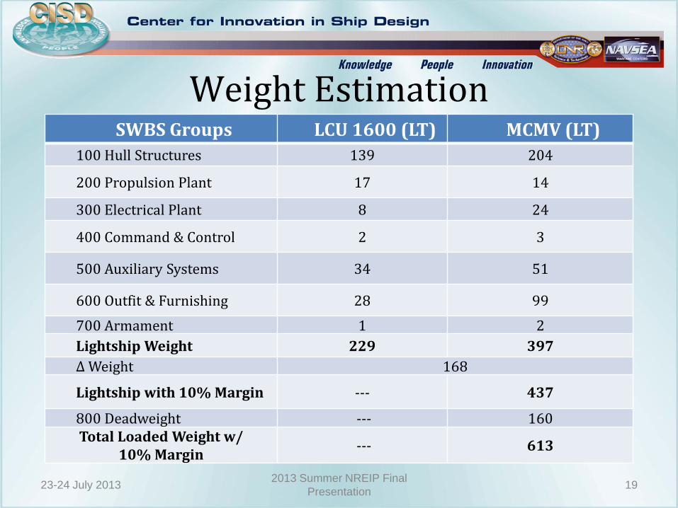
Weight Estimation SWBS Groups LCU 1600 (LT) MCMV (LT)
100 Hull Structures 139 204
200 Propulsion Plant 17 14
300 Electrical Plant 8 24
400 Command & Control 2 3
500 Auxiliary Systems 34 51
600 Outfit & Furnishing 28 99
700 Armament 1 2
Lightship Weight 229 397
∆ Weight 168
Lightship with 10% Margin --- 437
800 Deadweight --- 160 Total Loaded Weight w/
10% Margin --- 613
23-24 July 2013 19 2013 Summer NREIP Final
Presentation
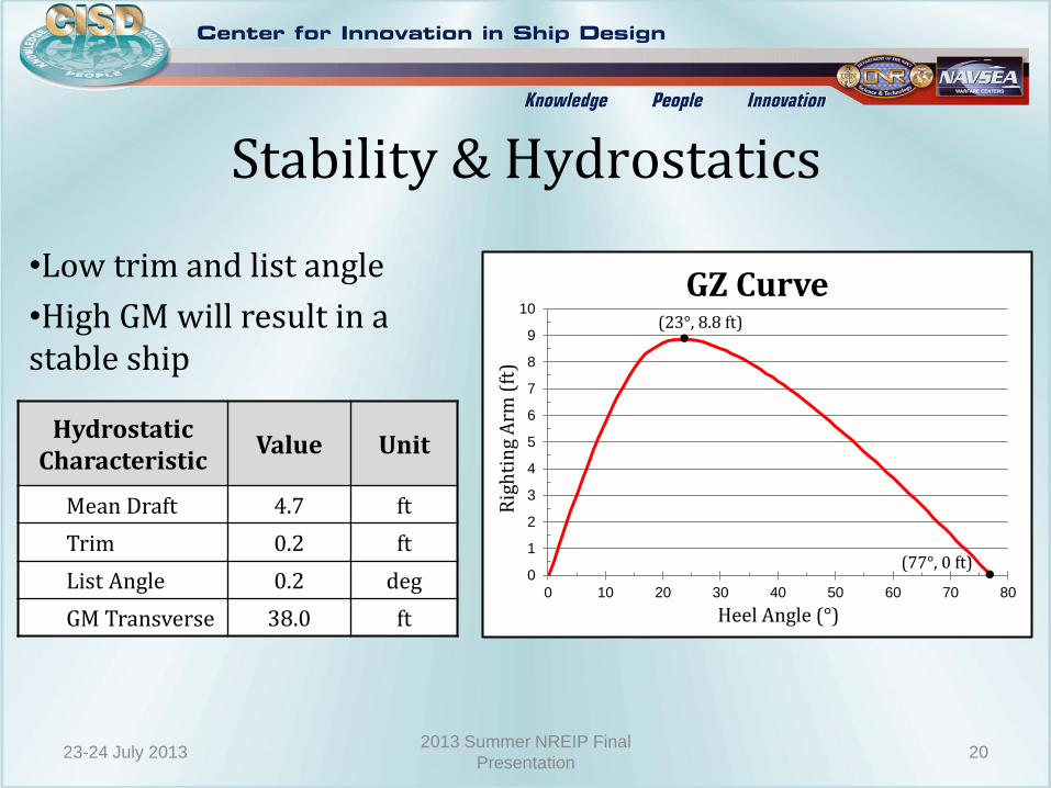
Stability & Hydrostatics
Hydrostatic Characteristic
Value Unit
Mean Draft 4.7 ft
Trim 0.2 ft
List Angle 0.2 deg
GM Transverse 38.0 ft
•Low trim and list angle
•High GM will result in a stable ship
0
1
2
3
4
5
6
7
8
9
10
0 10 20 30 40 50 60 70 80
Rig
hti
ng
Arm
(ft
)
Heel Angle (°)
GZ Curve (23°, 8.8 ft)
•
•
(77°, 0 ft)
23-24 July 2013 20 2013 Summer NREIP Final
Presentation

Resistance & Powering
Original Bow
Spoon Bow
TMB Bow
Comparison between three LCU (A) ship shape bows
Results include: •15% of frictional resistance for appendages •Model to full scale correlation allowance •Still air drag estimation •8% design margin
MCMV Parameters
LWL (ft) 180
Draft (ft) 4.7
Displacement (LT) 613
23-24 July 2013 21 2013 Summer NREIP Final
Presentation
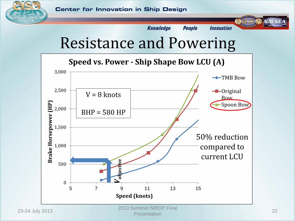
Resistance and Powering
0
500
1,000
1,500
2,000
2,500
3,000
5 7 9 11 13 15
Bra
ke
Ho
rse
po
we
r (H
P)
Speed (knots)
Speed vs. Power - Ship Shape Bow LCU (A)
TMB Bow
OriginalBowSpoon Bow
Vo
bje
ctiv
e
V = 8 knots
BHP = 580 HP
23-24 July 2013 22 2013 Summer NREIP Final
Presentation
50% reduction compared to current LCU

Electrical Load
0
200
400
600
800
1000
1200
1400
1600
MCM Vessel
Power (kW)
Powering Analysis
Winter LoadAvailable w/Margin
MCM UV's & LARSPower
Winter Load w/oMargin
Total Required Power 1500 kW
23-24 July 2013 23 2013 Summer NREIP Final
Presentation

Machinery Selection Endurance Requirements •2 to 10 days •50 nm radius from LPD-17
Desired Characteristics •Fuel efficient •High torque output •Reliable
Diesel-Electric 23-24 July 2013 24
2013 Summer NREIP Final
Presentation
Diesel-Electric Characteristics •Fuel consumption and propulsion electronically controlled •Increased payload •High reliability •Flexibility in location
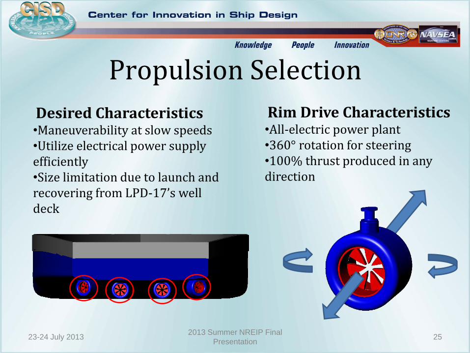
Propulsion Selection
Rim Drive Characteristics •All-electric power plant •360° rotation for steering •100% thrust produced in any direction
Desired Characteristics •Maneuverability at slow speeds •Utilize electrical power supply efficiently •Size limitation due to launch and recovering from LPD-17’s well deck
23-24 July 2013 25 2013 Summer NREIP Final
Presentation
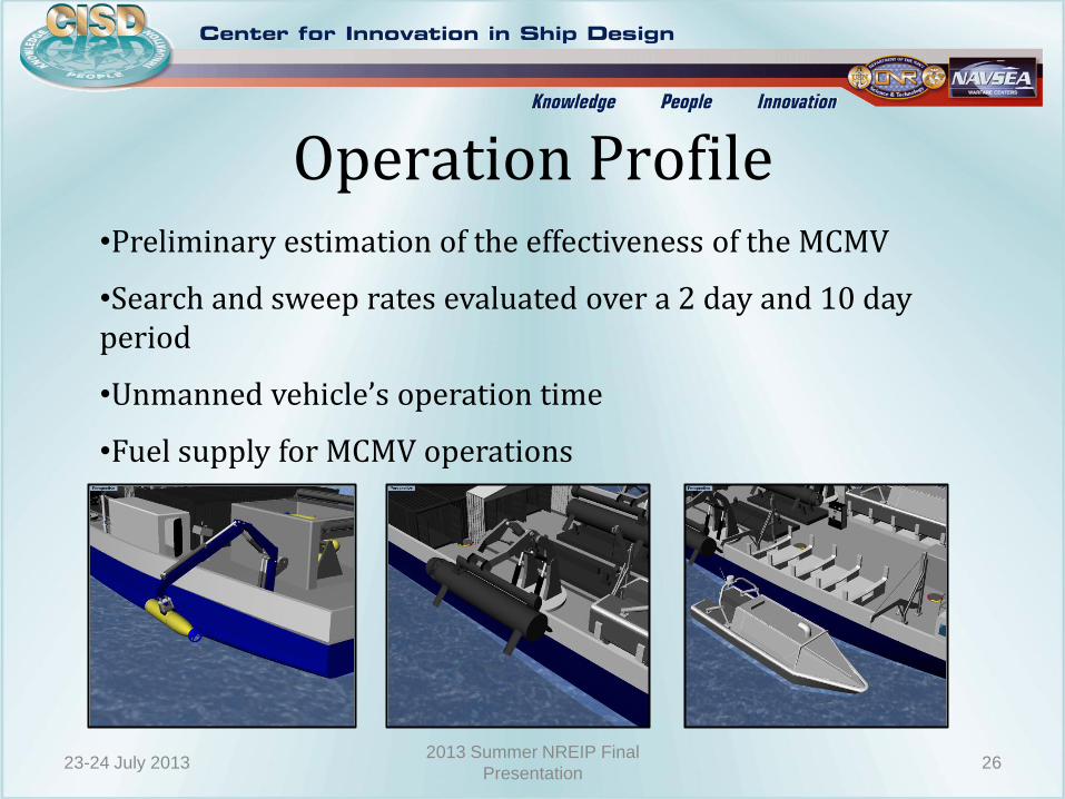
Operation Profile •Preliminary estimation of the effectiveness of the MCMV
•Search and sweep rates evaluated over a 2 day and 10 day period
•Unmanned vehicle’s operation time
•Fuel supply for MCMV operations
23-24 July 2013 26 2013 Summer NREIP Final
Presentation
27
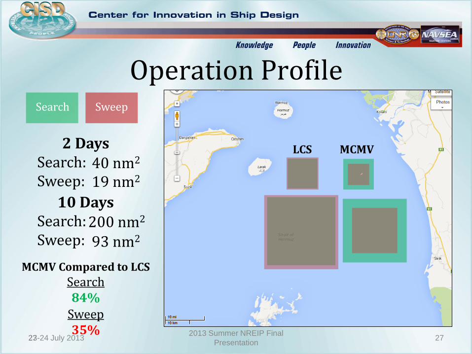
Operation Profile
2 Days Search:
Sweep:
`
40 nm2 19 nm2
10 Days Search:
Sweep: 200 nm2 93 nm2
Search Sweep
MCMV LCS
MCMV Compared to LCS
Search 84%
Sweep 35%
23-24 July 2013 27 2013 Summer NREIP Final
Presentation
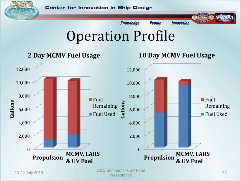
Operation Profile
0
2,000
4,000
6,000
8,000
10,000
12,000
Ga
llo
ns
2 Day MCMV Fuel Usage
FuelRemaining
Fuel Used
0
2,000
4,000
6,000
8,000
10,000
12,000
Ga
llo
ns
10 Day MCMV Fuel Usage
FuelRemaining
Fuel Used
Propulsion MCMV, LARS & UV Fuel
Propulsion MCMV, LARS & UV Fuel
23-24 July 2013 28 2013 Summer NREIP Final
Presentation
Conclusion
• As an alternative to LCS, the MCMV was deemed feasible for conducting MCM operations
– MCMV can host all off-board vehicles and LARS required for effective MCM
– It can be carried in the well deck of LPD-17
– Leaves LCS free for other operations
– Low impact integration to amphibious ship
– Available for training MCM personnel 29
2013 Summer NREIP Final
Presentation 23-24 July 2013
David Ruley
Colen Kennel
Ryan Mortimer
Jovan Brown
Julie Banner
Heather Tomaszek
Charles Dorger
Lt. Kevin Ray
Lt. John Arazny
2012 MCM Team
Acknowledgements
2013 Summer NREIP Final
Presentation 30 23-24 July 2013

Questions?
31 2013 Summer NREIP Final
Presentation 23-24 July 2013
BACKUP SLIDES
32 2013 Summer NREIP Final
Presentation 23-24 July 2013
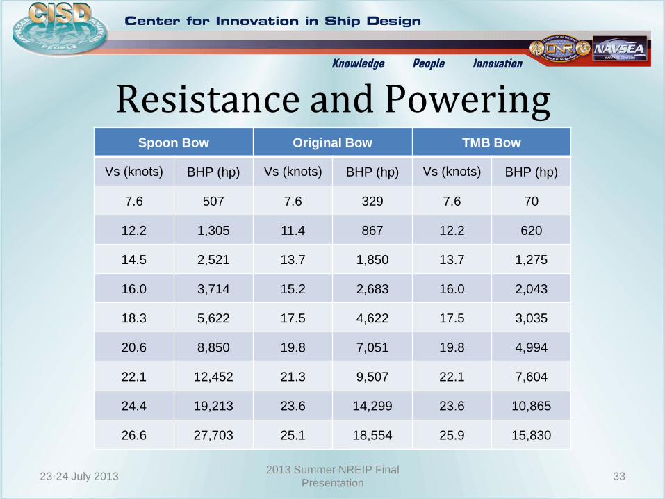
Resistance and Powering
33 2013 Summer NREIP Final
Presentation 23-24 July 2013
Spoon Bow Original Bow TMB Bow
Vs (knots) BHP (hp) Vs (knots) BHP (hp) Vs (knots) BHP (hp)
7.6 507 7.6 329 7.6 70
12.2 1,305 11.4 867 12.2 620
14.5 2,521 13.7 1,850 13.7 1,275
16.0 3,714 15.2 2,683 16.0 2,043
18.3 5,622 17.5 4,622 17.5 3,035
20.6 8,850 19.8 7,051 19.8 4,994
22.1 12,452 21.3 9,507 22.1 7,604
24.4 19,213 23.6 14,299 23.6 10,865
26.6 27,703 25.1 18,554 25.9 15,830

Machinery Selection Diesel-Electric
•Fuel efficient •Run on high loads with high efficiency •High torque •Multiple engine redundancy •Increased payload •Direct control over electrical system •Flexibility of location
Fuel Cell •Costs are lower than diesel •Low maintenance •High reliability •Noise reduction •Natural gas not as accessible as diesel fuel •Not a proven technology in marine systems
Gas Turbine •High power-to-weight ratio •Smaller than conventional engines •Better for larger ships due to high power output •Use more fuel when not under a load
34 2013 Summer NREIP Final
Presentation 23-24 July 2013

Propulsion Selection Screw Propeller
•Well developed and proven method •Good efficiency at high rotational speed •Relative insensitivity to ship motion •Maneuverability is restricted at slow speeds •Requires extra appendages
Podded Propulsor •Excellent maneuverability •Good speed control over complete range •Use of non-reversing machinery •Complicated Z-drive mechanism •Possibility of interference between podded propeller strut and hull
Water Jet •No appendages •Improved maneuverability •Higher static thrust can be obtain allowing fast acceleration •Less noise and vibration •Occupies a lot of space •Less efficient than propeller
Rim Drive •Reduced space requirements •High dynamic performance •100% thrust in both directions •Propeller design reduces cavitation risk •Need multiple drives to meet power requirements
35 2013 Summer NREIP Final
Presentation 23-24 July 2013

Operation Profile
36 2013 Summer NREIP Final
Presentation 23-24 July 2013
Propulsion Load Information
Speed (kts) Power (kW) 2 Day Time (hr) 10 Day Time (hr)
2 110 30 210
8 430 18 30
2 Day Operation
Unmanned
Vehicle Launch
(hr) Recover
(hr) Times
Ops.
Time (hr)
Ops.
Speed
(kts)
Fuel
(gal/hr) Fuel (gal)
# of
Vehicles
USV 1 1 2 7.5 25 20 300 1 BPAUV 1 1 3 10 3 n/a 3 RMV 1 1 2 10 12 15 300 1 RHIB 1 1 1 1 1
10 Day Operation
Unmanned
Vehicle Launch
(hr) Recover
(hr) Times
Ops.
Time (hr)
Ops.
Speed
(kts)
Fuel
(gal/hr) Fuel (gal)
# of
Vehicles
USV 1 1 10 7.5 25 20 1500 1
BPAUV 1 1 15 10 3 n/a 3
RMV 1 1 10 10 12 15 1500 1
RHIB 1 1 5 1 1


