56
1 © 2009 Artesis A.S. MCM User's Manual Document ID: MCM-OP-UM-EG-0091.0000
1
© 2009 Artesis A.S.
MCM User's Manual
Document ID: MCM-OP-UM-EG-0091.0000
2
MCM User's Manual
Lethal voltages and currents are present at the input terminals of this device. Accordingly, this MCM unitshould be installed and maintained only by qualified, competent personnel who have the necessary trainingand experience appropriate to high voltage and current devices. MCM must be used in accordance with alllocal and national codes for the installation and operation of electrical equipment.
Recommended safety precautions should be followed at all times. Both current and voltage transformers canpresent lethal currents and voltages when their primaries are energized and standard practices (i.e. shortingthe secondaries of current transformers and removing voltage transformer fuses) must be respected duringinstallation or any subsequent service.
The unit is designed for operation in a control cabinet with restricted access to the rear terminals and shouldnot be used in any environment where this is not the case. MCM should not be used for the purpose ofprimary protection of electrical equipment.
WARNING

i
All rights reserved. No part of this publication may be reproduced, stored in a retrieval system, or transmittedin any form or by any means, mechanical, photocopying, recording or otherwise, without prior writtenpermission of Artesis AS. No patent liability is assumed with respect to the information contained herein.
Whilst every effort has been made to ensure that the information presented in this document is accurate andup to date, Artesis AS reserves the right to make changes without notice. Neither Artesis AS nor itsdesignated agents can be held responsible for any errors or omissions, or problems arising from theapplication of information contained herein.
Neither Artesis AS nor its affiliates shall be liable to the purchaser of this product or third parties for damages,losses, costs, or expenses incurred by purchaser or third parties as a result of: accident, misuse or abuse ofthis product or unauthorized modifications, repairs, or alterations to this product, or failure to comply strictlyArtesis AS’s operating and maintenance instructions.
Artesis AS shall not be liable against damages or problems arising the use of any options or any consumableproducts other than those designated as Artesis original products or Artesis approved products by ArtesisAS.
Product names other than those owned by Artesis AS are used for identification purposes only and may betrademarks of their respective owners. Artesis AS disclaims any and all rights in those marks.
Copyright © Artesis 2009 by Artesis A.S., Gebze, Kocaeli, Turkey.
Motor Condition Monitor (MCM) and MCMSCADA
MCM User's Manual
ii
Table of ContentsMCM User's Manual
Table of Contents
Section I Welcome to MCM 1
................................................................................................................................... 11 Introduction
................................................................................................................................... 12 Use of this manual
Section II MCM Installation 3
................................................................................................................................... 31 Preliminary checks
................................................................................................................................... 32 MCM Unit Installation
................................................................................................................................... 43 Current and Voltage Sensor Installation
.......................................................................................................................................................... 4Low voltage line driven systems
.......................................................................................................................................................... 4Low voltage inverter driven systems
.......................................................................................................................................................... 5Medium/High voltage systems
................................................................................................................................... 54 Rear panel connections
................................................................................................................................... 65 Applying power to the MCM unit
................................................................................................................................... 76 Installing with soft-starter systems
................................................................................................................................... 77 Installing with inverter drives
Section III MCM Use 8
................................................................................................................................... 81 Introduction
................................................................................................................................... 82 The front panel
................................................................................................................................... 93 Configuring for use
.......................................................................................................................................................... 9Entering the password
.......................................................................................................................................................... 10The Edit Settings menu
......................................................................................................................................................... 10First time use
......................................................................................................................................................... 11Calibration factors
......................................................................................................................................................... 11Motor settings
......................................................................................................................................................... 11Communications settings
................................................................................................................................... 124 Running MCM
.......................................................................................................................................................... 12Introduction
.......................................................................................................................................................... 12Alarm messages and status indication
.......................................................................................................................................................... 13Running CHECK MOTOR
.......................................................................................................................................................... 14Setting and checking the input connections
.......................................................................................................................................................... 14Running LEARN and IMPROVE
.......................................................................................................................................................... 16Running RESUME and UPDATE
.......................................................................................................................................................... 17Advanced use
.......................................................................................................................................................... 19Equipment Faults and Their Diagnoses Using MCM
.......................................................................................................................................................... 21Interpreting MCM fault indications
......................................................................................................................................................... 21MCM status values
......................................................................................................................................................... 22Changes in line voltages
......................................................................................................................................................... 22Load changes
......................................................................................................................................................... 22Error messages
......................................................................................................................................................... 23Using the relay output
......................................................................................................................................................... 24Connecting to the serial port
iii
Table of ContentsMCM User's Manual
Section IV Troubleshooting 26
................................................................................................................................... 261 Introduction
................................................................................................................................... 262 Use of the MCM Config utility
................................................................................................................................... 293 Fault diagnosis
................................................................................................................................... 304 Servicing
Section V Appendices 31
................................................................................................................................... 311 Appendix 1: MCM Error, alarm and warning conditions
................................................................................................................................... 342 Appendix 2: Current and voltage sensor selection
................................................................................................................................... 363 Appendix 3: Connection Diagrams
................................................................................................................................... 394 Appendix 4: Menu settings and parameters
................................................................................................................................... 405 Appendix 5: Edit Settings Menu items
................................................................................................................................... 456 Appendix 6: Flowcharts for MCM use
................................................................................................................................... 517 Appendix 7: Continuous device ratings
1
Section 1 - Welcome to MCMMCM User's Manual
© 2009 Artesis A.S. Document ID: MCM-OP-UM-EG-0091.0000
1 Welcome to MCM
1.1 Introduction
MCM is a revolutionary tool in the battle to keep electric motors and machinery running at peakperformance, whilst maintaining high plant productivity levels. Used correctly, this unique instrument iscapable of monitoring three phase AC motors of all sizes and power levels to provide clear, unambiguousindications when the performance of a particular motor (or even the machinery it is connected to) beginsto degrade. The numerous transducers employed by other, less advanced instruments have beenreplaced by three current sensors and three voltage sensors, familiar to all those involved with themeasurement of electrical quantities, making the system straightforward to install and use without in-depth training of personnel.
In addition to its unique capabilities as an intelligent condition-monitoring device, MCM can also performmany of the functions of, and indeed replace the more traditional energy monitoring and data-logginginstruments.
For applications involving the monitoring of many motors and associated machinery, the networkingoptions available with MCM allow units to be connected together to a host terminal where they can all beviewed together.
Furthermore, the monitoring software package allows examination of the various parameters MCM usesto determine the status of a motor and to trend the parameters as a visual indication of degradation overtime.
Despite its simplicity and ease of use, like any intelligent electronic, software-based device, it isimportant that MCM is installed and used correctly. We recommend strongly that you take the time tostudy the information contained within the accompanying manuals and to familiarize yourself with theoperating principles and practices.
Customer service: Please contact either your supplier or Artesis AS Customer Service if youexperience any problems in the installation or use of MCM.
1.2 Use of this manual
This manual explains the basic concepts needed to install and use MCM. The appendix at the end of themanual provides information that may be useful to the general user. For further, specific details please

2
Section 1 - Welcome to MCMMCM User's Manual
© 2009 Artesis A.S. Document ID: MCM-OP-UM-EG-0091.0000
contact Artesis AS.
3
Section 1 - Welcome to MCMMCM User's Manual
© 2009 Artesis A.S. Document ID: MCM-OP-UM-EG-0091.0000
2 MCM Installation
2.1 Preliminary checks
Please inspect the contents of the MCM package and ensure that they agree with the information in thePacking list. In the event of any missing or damaged items, please contact your supplier immediately.Check also that the power range of the MCM unit is suitable for the motor to be monitored. The devicetype can be found on the MCM label. Artesis A.S. will not accept responsibility for damage caused to orby any MCM unit that has been incorrectly installed or installed on a motor system outside the indicatedpower range.
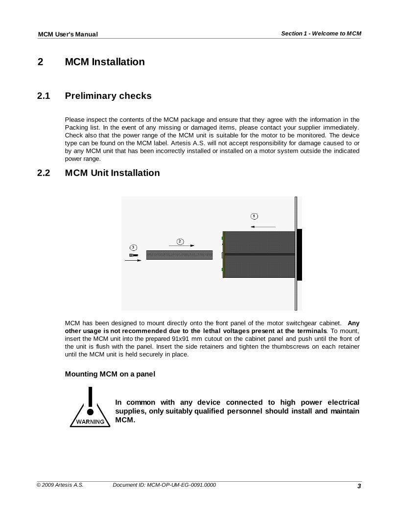
2.2 MCM Unit Installation
MCM has been designed to mount directly onto the front panel of the motor switchgear cabinet. Anyother usage is not recommended due to the lethal voltages present at the terminals. To mount,insert the MCM unit into the prepared 91x91 mm cutout on the cabinet panel and push until the front ofthe unit is flush with the panel. Insert the side retainers and tighten the thumbscrews on each retaineruntil the MCM unit is held securely in place.
Mounting MCM on a panel
In common with any device connected to high power electricalsupplies, only suitably qualified personnel should install and maintainMCM.
4
Section 2 - MCM InstallationMCM User's Manual
© 2009 Artesis A.S. Document ID: MCM-OP-UM-EG-0091.0000
2.3 Current and Voltage Sensor Installation
Dangerous and lethal voltages can develop across the secondaryterminals of open circuit current and voltage transformers. Beforedisconnecting any MCM unit to or from a current transformer, thesecondary terminals of the transformer should be shorted using a linkcapable of carrying at several times the nominal output current (i.e. atleast 10A). Before performing any work on a voltage transformer, itsfuse must be removed or switch opened. Contact breakers or fuses attheir sources must protect all voltage inputs.
2.3.1 Low voltage line driven systems
Three standard 5A secondary, current transformers of appropriate ratings are recommended for currentsensing (please refer to the appendix at the end of this manual for full specifications). The secondaryterminals of each transformer should be connected to the corresponding current measurement terminalpairs, I11-I12, I21-I22, I31-I32, on the rear of the MCM unit.
Voltage line connections VR, VS, VT should be made directly to their respective voltage measurement
terminals V1, V2, V3 at the rear of the unit.
Please refer to the connection diagrams in the appendix at the end of this manual for further details.
2.3.2 Low voltage inverter driven systems
The current sensors employed by MCM for inverter driven systems are Hall-effect type requiring anexternal DC power supply. The motor current rating should be checked carefully to ensure compatibilitywith the sensors provided. Please refer to the appendix at the end of this manual for further details onsensor selection.
High current sensors (for currents greater than 200 A) need to be mounted separately at a convenientlocation within the switchgear cabinet together with their external power supplies. Smaller sensors aremounted on the same circuit board as the power supply and should be placed together at the chosenlocation. In both cases, the cable carrying power to a single phase of the motor must be passed throughthe central hole in the appropriate current sensor and secured.
The power supply ground should be connected directly to the I12, I22, I32 pairs of current measurement
terminals on the rear of the MCM unit.Voltage connections VR, VS, VT should be made directly to their respective voltage measurement
terminals V1 V2 V3 at the rear of the unit.
Note that MCM is not recommended for use with inverters operating at a chopping frequencylower than 2 kHz.Please refer to the connection diagrams in the appendix at the end of this manual for further details.
5
Section 2 - MCM InstallationMCM User's Manual
© 2009 Artesis A.S. Document ID: MCM-OP-UM-EG-0091.0000
2.3.3 Medium/High voltage systems
Three standard 5A secondary, current transformers of appropriate ratings are recommended for currentsensing (please refer to the appendix at the end of this manual for full transformer specifications). Thesecondary outputs from each transformer should be connected to the corresponding currentmeasurement terminal pairs, I11-I12, I21-I22, I31-I32, on the rear of the MCM unit.
If compensation capacitors are employed, it is essential that the currenttransformers be placed between the motor and the capacitor bank so that onlythe true motor currents are measured.
Standard 100V, 110V and 120V secondary voltage transformers should be used to drop the voltage tousable levels. Connections from the secondary outputs of the transformers should be made to therespective voltage measurement terminals V1, V2 V3 at the rear of the unit.
Please refer to the connection diagrams in the appendix at the end of this manual for further details.
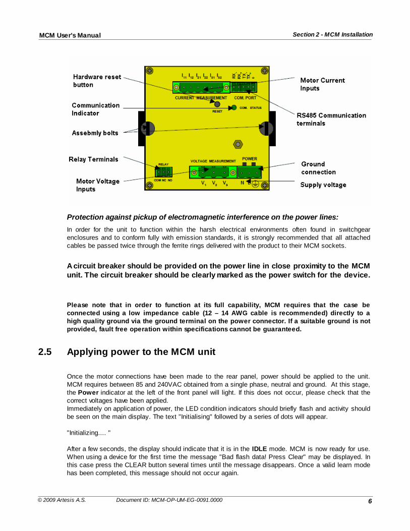
2.4 Rear panel connections
Connections to the MCM rear panel are given in the following figure. Lethal voltages can be present atthe voltage and current terminals and it is vitally important that power is removed from both the motorand the MCM unit prior to any connections being changed.
REMOVE ALL POWER PRIOR TO CHANGING CONNECTIONS
The three motor power voltages should be connected to the corresponding measurement terminals onthe MCM rear panel (R phase to V1, S phase to V2, and T phase to V3) using the connectors provided.
Similarly, the IR, IS, IT connections from the current sensors should be made to the appropriate current
terminal pairs, I11-I12, I21-I22, I31-I32, on the upper part of the rear panel. It is not essential that the all three
sets of phases have the correct phase relationship as the phase ordering is determined by MCM.The order of these voltage and current pairs is not important as MCM determines the correct orderingwhen CHECK MOTOR is first run on the device
6
Section 2 - MCM InstallationMCM User's Manual
© 2009 Artesis A.S. Document ID: MCM-OP-UM-EG-0091.0000
Protection against pickup of electromagnetic interference on the power lines:
In order for the unit to function within the harsh electrical environments often found in switchgearenclosures and to conform fully with emission standards, it is strongly recommended that all attachedcables be passed twice through the ferrite rings delivered with the product to their MCM sockets.
A circuit breaker should be provided on the power line in close proximity to the MCMunit. The circuit breaker should be clearly marked as the power switch for the device.
Please note that in order to function at its full capability, MCM requires that the case beconnected using a low impedance cable (12 – 14 AWG cable is recommended) directly to ahigh quality ground via the ground terminal on the power connector. If a suitable ground is notprovided, fault free operation within specifications cannot be guaranteed.
2.5 Applying power to the MCM unit
Once the motor connections have been made to the rear panel, power should be applied to the unit.MCM requires between 85 and 240VAC obtained from a single phase, neutral and ground. At this stage,the Power indicator at the left of the front panel will light. If this does not occur, please check that thecorrect voltages have been applied.Immediately on application of power, the LED condition indicators should briefly flash and activity shouldbe seen on the main display. The text "Initialising" followed by a series of dots will appear.
"Initializing.... "
After a few seconds, the display should indicate that it is in the IDLE mode. MCM is now ready for use.When using a device for the first time the message "Bad flash data! Press Clear" may be displayed. Inthis case press the CLEAR button several times until the message disappears. Once a valid learn modehas been completed, this message should not occur again.
7
Section 2 - MCM InstallationMCM User's Manual
© 2009 Artesis A.S. Document ID: MCM-OP-UM-EG-0091.0000
2.6 Installing with soft-starter systems
MCM can be installed with standard soft-starter systems provided that they are automatically bypassedimmediately after motor start-up and during subsequent use. Un-bypassed, soft-starter systems canintroduce considerable distortion into the current waveforms and thus prevent MCM from modeling theproperties of the motor itself. If MCM is to be used with such a system, it is essential that the maximumcurrent limit of the starter be above the nominal running motor current so that it is bypassed effectivelyduring all normal operation. MCM should never be used on a system that employs soft-starters forspeed control or other un-bypassed uses. Please refer to the diagrams in the appendix for details ofthe connections needed for soft starter systems. Soft-starters should always be bypassed.
2.7 Installing with inverter drives
Using MCM with inverter driven motors requires the same voltage connections specified for line drivensystems. External Hall-effect current sensors must be used with inverter systems, as normal currenttransformers have insufficient bandwidth for use with the range of frequencies obtainable from inverters.Please refer to the diagram in the appendix for details of the connections needed for inverter drivensystems.
8
Section 2 - MCM InstallationMCM User's Manual
© 2009 Artesis A.S. Document ID: MCM-OP-UM-EG-0091.0000
3 MCM Use
3.1 Introduction
Use of MCM is both simple and straightforward once the basic concepts and principles are understood.This section of the manual is designed to introduce these concepts and to demonstrate how MCM is setup, how to check all the connections and settings, how MCM learns the characteristics of the system itwill monitor and finally how to actually monitor the motor system. It is recommended that first time usersread this section carefully, as successful operation requires that MCM is set up and used correctly. Flowcharts for the main operations are provided in the appendix at the end of this manual to help usersnavigate their way through the various steps involved with setting and running MCM for the first time.
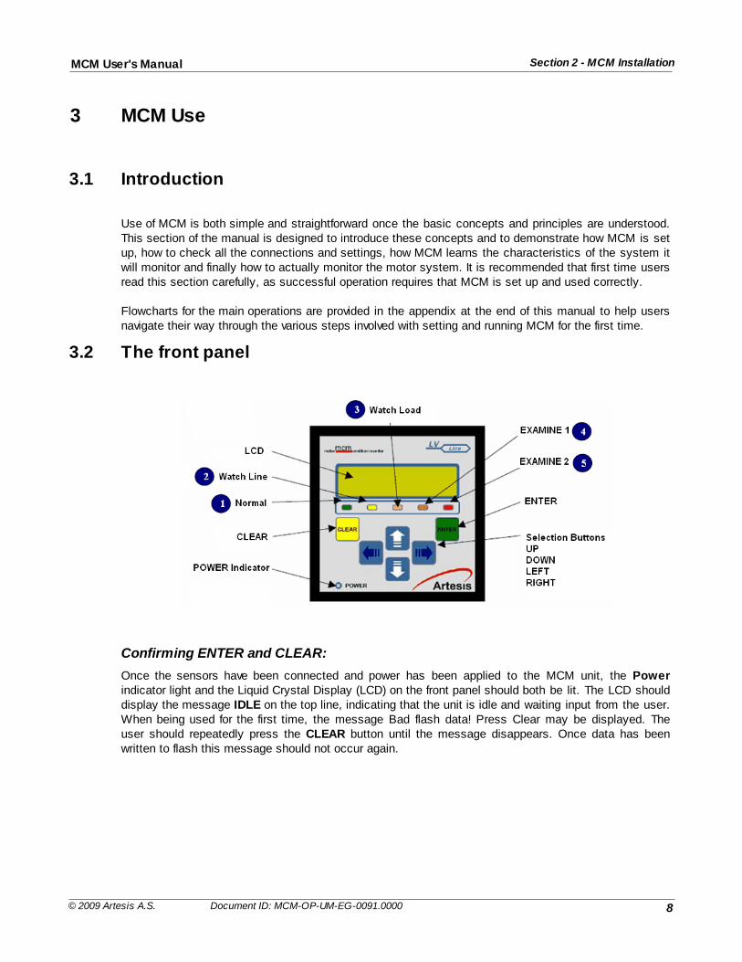
3.2 The front panel
Confirming ENTER and CLEAR:
Once the sensors have been connected and power has been applied to the MCM unit, the Powerindicator light and the Liquid Crystal Display (LCD) on the front panel should both be lit. The LCD shoulddisplay the message IDLE on the top line, indicating that the unit is idle and waiting input from the user.When being used for the first time, the message Bad flash data! Press Clear may be displayed. Theuser should repeatedly press the CLEAR button until the message disappears. Once data has beenwritten to flash this message should not occur again.
9
Section 3 - MCM UseMCM User's Manual
© 2009 Artesis A.S. Document ID: MCM-OP-UM-EG-0091.0000
Using the front panel buttons:
Commands are input by pressing one of the six selection buttons on the front of the unit, UP, DOWN,LEFT, RIGHT, ENTER and CLEAR. For instance, the user can cycle through the various modes (IDLEto CHECK MOTOR to RUN to RESUME … and finally back to IDLE), by repeatedly pressing the UPbutton. A particular mode can be selected by pressing ENTER when the desired mode is displayed onthe LCD. The menus are set up on a hierarchical basis, with each level representing commands of thesame precedence which the user can cycle through by pressing the UP or DOWN buttons. PressingCLEAR has the effect of stopping a particular action and rising up a level in the hierarchy. Only EditSettings has nested hierarchy levels more than two deep. In general whenever ENTER or CLEAR ispressed, it will be necessary to confirm the action with a second press of the button; pressing the otherbutton (i.e. CLEAR after ENTER and vice versa) will cancel the action.
Setting numeric values:
Similarly, numeric values can be entered using the arrow buttons. When a value is to be changed, usethe LEFT or RIGHT buttons to move the LCD flashing cursor to the first digit to be edited and repeatedlypress either the UP or DOWN buttons to scroll through the available alphanumeric characters until thedesired one is displayed. Subsequent digits can be edited by moving to the next digit using the LEFT orRIGHT buttons and again scrolling with the UP and DOWN buttons. A schematic diagram showing the menu hierarchy is shown in the appendix at the end of this manual.
3.3 Configuring for use
Master reset:
When first installed, the MCM unit will be configured for the default, factory settings which will need to bechanged prior to use. At later times, the factory settings can be restored by pressing and holding downthe LEFT button for about 4 seconds during power up of the device, until the string; Press ENTER forgeneral reset appears. At this stage pressing ENTER will initiate the reset. Pressing any other buttonwill cause the reset to be ignored and the device will continue.
3.3.1 Entering the password
To configure the unit, select the Edit Settings mode and press and confirm ENTER. In order to proceedfurther, it will be necessary to enter a password. The factory setting for this password is the string “m“and can be entered using the UP and DOWN buttons to cycle through the alphanumeric characters (‘a’through ‘z’, ‘0’ through ‘9’). The LEFT and RIGHT buttons are used to shift the active character in thestring. To input the password “m”, repeatedly press the UP button until the letter ‘m’ appears in the firstposition. Press and confirm ENTER and then press ENTER again to enter the Edit Settings menu. It is recommended that at a later time the password be changed, in order to prevent unauthorizedaccess to the device.
10
Section 3 - MCM UseMCM User's Manual
© 2009 Artesis A.S. Document ID: MCM-OP-UM-EG-0091.0000
3.3.2 The Edit Settings menu
At this level the following Edit Settings menu items are accessible:
Motor valuesHarmonic valuesComm. settingsMotor settingsCalibration
Alarm thresholdsVersionsRun settingsPhase OrderingChange password
Editing and displaying menu items:
Please refer to the appendix for a table of these menus and their sub-menu items. To edit a particularitem, first select the item to edit and press and confirm ENTER. As before use the UP and DOWNbuttons to scroll vertically through individual digits and the LEFT and RIGHT buttons to change the digitbeing edited. Some variables can only take discrete values represented by character strings and in thiscase vertical scrolling will shift through the allowed values. For example, the Parity value under theCommunications settings menu can only have the values EVEN or ODD and scrolling will repeatedlycycle through these values.
Menu paths:
Throughout this manual, paths to menu items are represented by the word MENU: followed by the list ofsub-menus required to reach the item separated by a forward slash. For example the path of the Parityvalue given in the preceding paragraph would be given as:
MENU: Edit Settings / Password / Comm. Settings / Parity
The forward slash can be thought to represent the action of pressing and confirming ENTER.
Local Lockout and passwords:
Some modes can be protected for supervised access by setting the local lockout setting.
MENU: Edit Settings / Password / Run Settings / Local Lockout
If this mode is set, access to the following modes is password protected:
(i) CHECK MOTOR(ii) RUN(iii) RESUME(iv) UPDATE
In addition, canceling any of these modes by pressing CLEAR also requires the user to supply apassword. All passwords are the same as that used to access Edit Settings.
3.3.2.1 First time use
Before MCM can be used for the first time it is necessary to change various settings from their defaultvalues (a table outlining the MCM settings is shown in the appendix). Values relevant to the connectedmotor must be set for the quantities described in the following sections.
11
Section 3 - MCM UseMCM User's Manual
© 2009 Artesis A.S. Document ID: MCM-OP-UM-EG-0091.0000
3.3.2.2 Calibration factors
Hall-effect current sensors and assemblies supplied with MCM should be accompanied by a calibrationdocument containing the sensor’s calibration factor. The values of each calibration factor should beentered into the correct setting under the Calibration menu. It is important that the correct factor beentered for each channel, as MCM will not function correctly if the calibration factors are incorrect.
For channels connected to transformer sensors, the calibration factor should be equal to the nominalratio of the primary to secondary turns. For example a 100A current transformer with a 5A output and asingle primary turn would require a calibration factor of 20. The same transformer with two primary turnswould require a calibration factor of 10. A 6500V voltage transformer with a nominal secondary voltage of100V would require a calibration factor of 65. Any channel connected directly to the motor without anexternal sensor (i.e. voltage connections on low voltage units) requires a calibration factor of 1.
3.3.2.3 Motor settings
Nominal voltage, current and frequency:
The nominal voltage, current and speed (in rpm) of the attached motor must be entered under the MotorSettings menu. These values can be obtained from the motor specifications. MCM uses these values todetermine whether the motor complies with its specifications and incorrect values are likely to raisealarms. The nominal line frequency (or most commonly expected frequency in the case of an inverter)should also be set. Similarly, the motor connection type must be set to one of Star or Delta.
3.3.2.4 Communications settings
Setting the device address:
If the MCM networking options are to be used, the MCM network address must be supplied. By defaultthis is set to 0, which by convention is the address of the host terminal. Use of this address willtherefore disrupt communications over the network and must be changed prior to connection. Anyaddress between 1 and 255 can be selected although it is important to check that the selected addressis not in use by any other device on the same node. Please refer to the MCMViewPro networkingdocumentation for full details of address selection.
It is recommended that the motor serial number (or any other short identifier string) be entered as ameans of identifying the motor to the software. This is not obligatory, and both the networking softwareand MCM can function without this information.
Other communications settings:
All other communications settings should be left at the factory defaults if the MCMSCADA networkingsoftware is being used. If another software package is employed (i.e. SCADA software), please refer toits documentation for communication settings.MCM can use both 2 and 4 wire (RS 422 and RS485 standards respectively) communications at up to19200 Baud. Please refer to section 4.4.12 for further information.
12
Section 3 - MCM UseMCM User's Manual
© 2009 Artesis A.S. Document ID: MCM-OP-UM-EG-0091.0000
3.4 Running MCM
3.4.1 Introduction
Having configured MCM for a particular motor, it can now be used for its intended purpose of monitoringand assessing the condition of the motor. In general, this involves first running MCM to measure andlearn the properties of the motor and then running MCM in its test mode to perform the actualmonitoring. Without the learning period MCM has insufficient information on which to base itsdecisions as the motor ages and will not perform to its specifications. For this reason, MCMensures that a valid learning period is first performed before allowing the user to request the device tomonitor the motor.
3.4.2 Alarm messages and status indication
Alarms specific to the motor:
MCM divides warning messages into the categories of warnings, alarms and errors. Warnings inform theuser that non-critical conditions have arisen that the user should be aware of but do not affect theperformance of MCM. Alarms provide information specific to the motor being tested and are indicationsof faults caused by incorrect connections to the motor, the supplied line voltage and/or motor currentsbeing outside the specified limits and other conditions that prevent MCM from correctly determining thestate of the motor. Alarms do not cause MCM to stop monitoring completely, but generally areindications that there is something that needs to be investigated and possibly changed before MCM canfunction to its full extent. In some cases an alarm may indicate a transient event such as high linevoltages, which although damaging to the motor in the long term, do not indicate an immediate need foraction. Of course if the frequency of such events is sufficiently high, the cause should be located andcorrective action taken to remedy the problem. It is important to realize that when an alarm isdisplayed, MCM cannot monitor the motor status. It is therefore important to ascertain the cause ofthe alarm at the earliest opportunity.
Viewing alarm messages:
An alarm is indicated on the front panel of MCM by the message Alarm followed by a hexadecimal value.The bits of the hexadecimal value refer to which alarm is raised. Repeatedly pressing the RIGHT orLEFT buttons cycles through a list of all active alarms. Please refer to the appendix for a complete list ofpossible alarm conditions and their remedies. The measured physical motor values can be viewed duringan alarm by pressing the UP or DOWN buttons. This is often useful in determining the reason for analarm.
Fault status indication:
STATUSSTRING
LEDNo
Fault Severity
LEARN MCM has insufficient data to assess the status of equipment
NORMAL 1 Motor is healthy or level of failure is under alarm thresholds
WATCH LINE 2
There is a changing on the supply voltage of the motor. Temporarychanges in supply voltage cause this alarm. If alarm is persistent check;harmonic levels, capacitors, isolation of cables, motor connector or terminalslackness, loose contactors, etc.
13
Section 3 - MCM UseMCM User's Manual
© 2009 Artesis A.S. Document ID: MCM-OP-UM-EG-0091.0000
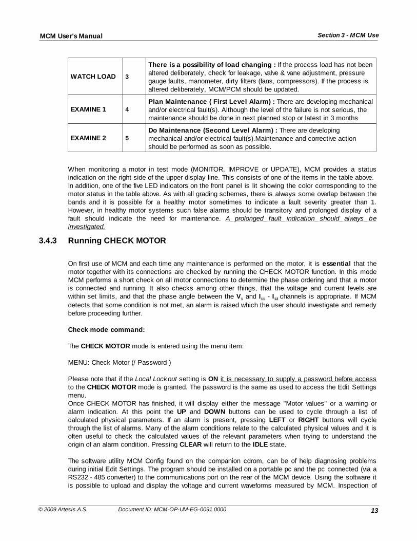
WATCH LOAD 3
There is a possibility of load changing : If the process load has not beenaltered deliberately, check for leakage, valve & vane adjustment, pressuregauge faults, manometer, dirty filters (fans, compressors). If the process isaltered deliberately, MCM/PCM should be updated.
EXAMINE 1 4Plan Maintenance ( First Level Alarm) : There are developing mechanicaland/or electrical fault(s). Although the level of the failure is not serious, themaintenance should be done in next planned stop or latest in 3 months
EXAMINE 2 5Do Maintenance (Second Level Alarm) : There are developingmechanical and/or electrical fault(s).Maintenance and corrective actionshould be performed as soon as possible.
When monitoring a motor in test mode (MONITOR, IMPROVE or UPDATE), MCM provides a statusindication on the right side of the upper display line. This consists of one of the items in the table above.In addition, one of the five LED indicators on the front panel is lit showing the color corresponding to themotor status in the table above. As with all grading schemes, there is always some overlap between thebands and it is possible for a healthy motor sometimes to indicate a fault severity greater than 1.However, in healthy motor systems such false alarms should be transitory and prolonged display of afault should indicate the need for maintenance. A prolonged fault indication should always beinvestigated.
3.4.3 Running CHECK MOTOR
On first use of MCM and each time any maintenance is performed on the motor, it is essential that themotor together with its connections are checked by running the CHECK MOTOR function. In this modeMCM performs a short check on all motor connections to determine the phase ordering and that a motoris connected and running. It also checks among other things, that the voltage and current levels arewithin set limits, and that the phase angle between the V1 and I11 - I12 channels is appropriate. If MCM
detects that some condition is not met, an alarm is raised which the user should investigate and remedybefore proceeding further.
Check mode command:
The CHECK MOTOR mode is entered using the menu item:
MENU: Check Motor (/ Password )
Please note that if the Local Lockout setting is ON it is necessary to supply a password before accessto the CHECK MOTOR mode is granted. The password is the same as used to access the Edit Settingsmenu.Once CHECK MOTOR has finished, it will display either the message "Motor values" or a warning oralarm indication. At this point the UP and DOWN buttons can be used to cycle through a list ofcalculated physical parameters. If an alarm is present, pressing LEFT or RIGHT buttons will cyclethrough the list of alarms. Many of the alarm conditions relate to the calculated physical values and it isoften useful to check the calculated values of the relevant parameters when trying to understand theorigin of an alarm condition. Pressing CLEAR will return to the IDLE state.
The software utility MCM Config found on the companion cdrom, can be of help diagnosing problemsduring initial Edit Settings. The program should be installed on a portable pc and the pc connected (via aRS232 - 485 converter) to the communications port on the rear of the MCM device. Using the software itis possible to upload and display the voltage and current waveforms measured by MCM. Inspection of
14
Section 3 - MCM UseMCM User's Manual
© 2009 Artesis A.S. Document ID: MCM-OP-UM-EG-0091.0000
these waveforms can reveal problems caused by missing phases, phase ordering, phase imbalance etc.Please refer to the MCM Config documentation and to the trouble shooting section of this manual forfurther details.
3.4.4 Setting and checking the input connections
When the CHECK MOTOR menu option is selected, MCM first determines the relative order of thevoltage phases using the V1 channel as an arbitrary reference. It then attempts to place the current
channel pairs in the correct order and polarity. The order determined by MCM can be displayed byentering the EDIT SETTINGS menu and selecting:
MENU: Edit Settings / Phase Ordering / Phase Order
On this menu, the voltages are denoted by the letters R, S, T and currents by r, s, t. A – sign precedingeach letter indicates that the corresponding signal has an extra 180º of phase shift (i.e. that the polarityof the signal is reversed). Similarly, a + sign preceding a letter indicates that the polarity is correct. Forexample:
The above phase ordering display would indicate that relative to the first voltage (R) phase on input V1,
the S and T phases (on V3 and V2 respectively) are reversed. The order of the current inputs is also
incorrect with IS connected to I11 - I12, IR connected to I21 - I22 and IT connected to I31 - I32. Furthermore, the
polarities of the two currents, IS and IT, have been reversed (I11 has been exchanged with I12 and I31 with I32).
Please note that once MCM has determined the correct phases, the user should not change the inputconnections without running CHECK MOTOR again.
The algorithm used by MCM to determine the phase order yields two solutions depending on the motorloading and extra information is required to obtain the correct sequence. To this end, MCM comparesthe measured RMS values for the currents with the nominal current entered by the user. If the ratio of themeasured current to the nominal current is greater than the value of the Load threshold (expressed as apercentage), the motor is assumed to be working under loaded conditions and the appropriate solution ischosen. Otherwise the motor is assumed not to be loaded. It is thus important to enter an accuratevalue for the nominal current. Even so, it is still possible for MCM to choose the wrong solution which willyield unrealistic values for the phase angle when the loading on the motor changes in use. MCMprovides the possibility of overriding the detected phase sequence from the menu item Order Overrideunder:
MENU: Edit Settings / Phase Ordering / Order Override
Changing the value of this item from OFF to ON allows the detected phase ordering to be altered bymoving the cursor to the required position and scrolling UP/DOWN to select the desired value.It is also possible to fine-tune the algorithm by altering the value of the load threshold. A higher value willtend to favour the unloaded solutions and vice versa. The load threshold can be found under:
MENU: Edit Settings / Alarm Thresholds / Load threshold
3.4.5 Running LEARN and IMPROVE
LEARN:
MCM should learn the motor under normal operating conditions. The LEARN period consists of a presetnumber of data acquisition cycles and periods of data analysis. Once the preset number of cycles hasbeen reached, the acquired and pre-processed data are further processed to produce a database
15
Section 3 - MCM UseMCM User's Manual
© 2009 Artesis A.S. Document ID: MCM-OP-UM-EG-0091.0000
consisting of a collection of data sets representing the behavior of the motor system under the loadconditions that the motor has met in practice. It is therefore important to have the motor operating underits expected running conditions during a learning period. In order to cover adequately the range of loadconditions experienced by a motor system, a sufficient number of acquisition cycles or iterations isrequired. It has been found that 4000 iterations provides adequate coverage under most conditions and itis recommended that between 3000 and 4000 iterations are used. Since additional learning can also beperformed if needed during the testing phase, a larger number of learning iterations is not generallyrequired. The number of learning iterations can be set from the menu path:
MENU: Edit Settings / Password / Run settings / Learn iterants
IMPROVE:
Selecting RUN from the main menu will initiate a new LEARN period. If data from a previous leaningperiod exist, the following message will be displayed:
"Lose learn Data? Clear to exit"
The user should press the CLEAR button if it is not desired to overwrite the existing data and ENTER if itis. Once the initial learning period is complete, the MCM unit automatically will try to improve its estimationof the motor characteristics. To update the database obtained during the learning mode for different loadand line conditions until sufficient data have been amassed, as determined by the number of Improveiterations set from the menu path
MENU: Edit Settings/Password / Run settings / Improve Iterations
It is recommended that this value be set to between 8000 – 10000 iterations.An important difference between this mode and the initial learning period is that MCM monitors the motorstatus during IMPROVE but does not during LEARN. Once the IMPROVE stage is complete, the MONITOR phase will automatically continue without userintervention. This is the main operating mode and MCM is expected to spend most of its time in thismode monitoring attached motor systems. In order to start monitoring, MCM must first have learnt thecharacteristics of the motor it is to monitor and have a valid learning mode.
Iteration cycle time:In general a data processing cycle takes between 60 – 120 seconds depending on several factors.Firstly, MCM requires relatively unchanging data over a minimum time period during its data acquisitionphase and will repeat the data acquisition until it obtains stable data, thus varying the iteration timecycle. If the amplitude or frequency of the voltage and current phases varies excessively and stable datacannot be found, an alarm is raised. Secondly, if harmonic values are being calculated, extra processingcycles are required. Finally, if MCM encounters an error, it may repeat the cycle several times.Please note that if the Local Lockout setting is ON it is necessary to supply a password before accessto any learning or monitoring mode is granted.Once started, the monitoring process will continue until one or other of the following conditions isfulfilled:1. An error condition is generated and cancelled2. The user presses the CLEAR button to cancel the process. In order to prevent unauthorized access, ifthe Local Lockout setting is set a password must first be entered.3. Power to the MCM unit is cut.
Alarms during the monitoring process:Alarm conditions may occur during any monitoring phase. If CHECK MOTOR has previously been run on
16
Section 3 - MCM UseMCM User's Manual
© 2009 Artesis A.S. Document ID: MCM-OP-UM-EG-0091.0000
the motor, it is likely that the alarms represent transient conditions present on the power lines. However,it is suggested that any alarm representing a condition that could affect the performance of the motorshould be recorded and investigated as a potential cause of motor degradation. As in CHECK MOTOR, ifan alarm is indicated, the most recent physical values available for the motor can be displayed using the UP and DOWN buttons. Examination of these values can often indicate the precise reason for the alarmcondition. A complete list of alarm conditions can be found in the appendix at the end of this manual.
Using an inverter drive:If an inverter is being used to drive the motor, several additional precautions are needed. The voltagefrequency is expected to be constant (within well defined limits) for direct line driven motors, but can varyconsiderably when an inverter is used. MCM can handle the range of frequencies typical of an inverter,but first needs to learn the motor at a single frequency representative of the conditions it will meet inpractice. The value of this dominant frequency must be entered from the Edit Settings menu. If MCMmeasures the frequency to be out of the expected range, it will issue an alarm in both the CHECKMOTOR and LEARN modes and the user should adjust the frequency setting accordingly. DuringIMPROVE, UPDATE and MONITOR, this requirement is relaxed and the frequency can assume anyvalue within the allowed frequency range. Please note that MCM is not suitable for followingapplications :
1. If motor supply voltage is changing over 15% in 6 seconds,2. If motor current is changing over 15% in 6 seconds,3. DC motors,4. If motor is driven by a inverter whose chopping frequency is under 2 kHz.
3.4.6 Running RESUME and UPDATE
Canceling running:All the operating modes LEARN, IMPROVE, MONITOR and UPDATE can be stopped and started atany time without significant effect on monitoring performance, by pressing the CLEAR button (andproviding the correct password if Local Lockout is ON). Subsequent restart of MCM can be achieved byselecting RESUME from the main menu, which will cause MCM to continue in its incomplete mode atthe point of interruption. Thus if it is necessary to stop MCM for any reason, it can be restarted withoutaffecting any existing data.
UPDATE:At subsequent times it may be desirable to learn a new operating point of the motor. This can be doneusing the UPDATE function. This can be reached either from the main menu in IDLE mode or bypressing first the RIGHT and then the ENTER button during MONITOR.
Updating the internal database:When MCM first starts in the MONITOR, IMPROVE or UPDATE modes, it has insufficient data toindicate the motor status accurately. Under such conditions a blank string may be displayed instead ofthe motor status. This is a temporary condition and should last only for the first data cycle. As a resultof internal error handling, the blank string may occasionally be seen. Again, this is temporary and willpass by the start of the next data cycle.Although MCM should have met the majority of working conditions in the learning mode, it is stillpossible for it to fail to recognize a particular working point. In such a case, the user can elect to add thecurrent operating point to the internal database using the UPDATE feature. Running UPDATE will causethe internal database to be updated with the new information over a preset number of cycles. Once thecount of iterations exceeds the preset number, MCM will automatically return to MONITOR without userintervention. The number of update cycles can be set from
17
Section 3 - MCM UseMCM User's Manual
© 2009 Artesis A.S. Document ID: MCM-OP-UM-EG-0091.0000
MENU: Edit Settings / Password / Run settings / Update iterations
If it is necessary to learn the new operating conditions of the motor in order to add them to the existingdatabase, UPDATE can be started in two ways. Firstly, in IDLE mode, the Update option should beselected and ENTER pressed. Secondly, from MONITOR, the RIGHT button should be pressed todisplay the message:
"Press ENTER for UPDATE"
and then ENTER pressed to select the mode.As in the learning mode, sequentially pressing the UP or DOWN buttons allows the user to select anddisplay the most recent values for the parameters calculated by MCM.
3.4.7 Advanced use
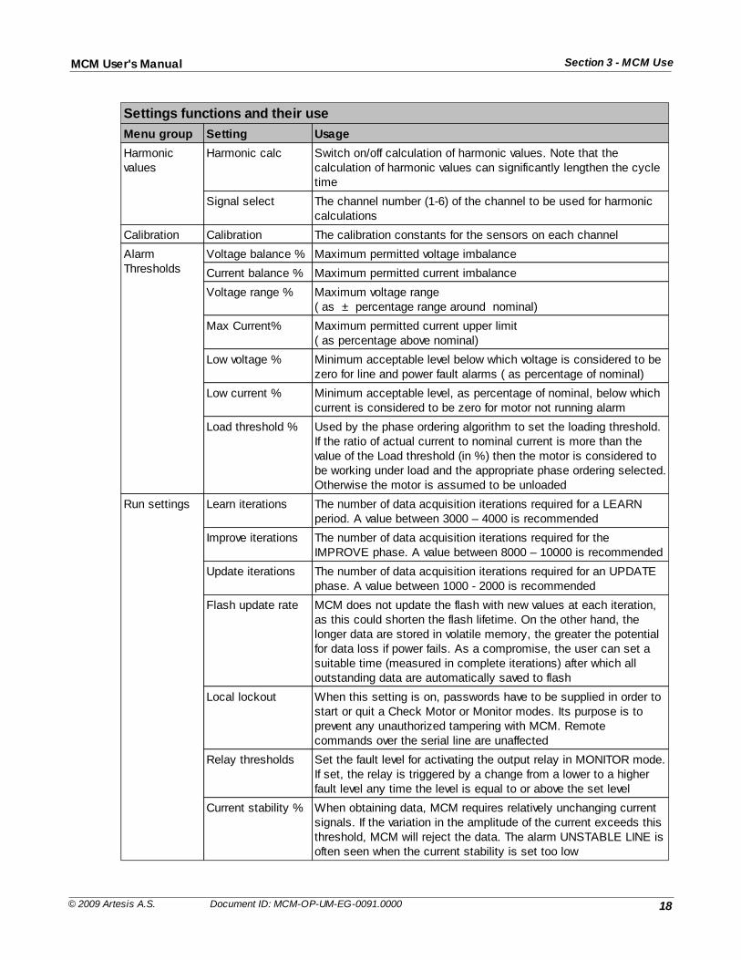
It is possible to customize the behavior of MCM by adjusting various settings. As usual a valid passwordmust be supplied before the Edit Settings menu can be entered. The following table summarizes thesettings that can be changed together with their significance. It is recommended that the original valuesof each setting be recorded prior to changing them. After changing certain settings it may be necessaryto relearn the motor.
18
Section 3 - MCM UseMCM User's Manual
© 2009 Artesis A.S. Document ID: MCM-OP-UM-EG-0091.0000
Settings functions and their use
Menu group Setting Usage
Harmonicvalues
Harmonic calc Switch on/off calculation of harmonic values. Note that thecalculation of harmonic values can significantly lengthen the cycletime
Signal select The channel number (1-6) of the channel to be used for harmoniccalculations
Calibration Calibration The calibration constants for the sensors on each channel
AlarmThresholds
Voltage balance % Maximum permitted voltage imbalance
Current balance % Maximum permitted current imbalance
Voltage range % Maximum voltage range ( as ± percentage range around nominal)
Max Current% Maximum permitted current upper limit ( as percentage above nominal)
Low voltage % Minimum acceptable level below which voltage is considered to bezero for line and power fault alarms ( as percentage of nominal)
Low current % Minimum acceptable level, as percentage of nominal, below whichcurrent is considered to be zero for motor not running alarm
Load threshold % Used by the phase ordering algorithm to set the loading threshold.If the ratio of actual current to nominal current is more than thevalue of the Load threshold (in %) then the motor is considered tobe working under load and the appropriate phase ordering selected.Otherwise the motor is assumed to be unloaded
Run settings Learn iterations The number of data acquisition iterations required for a LEARNperiod. A value between 3000 – 4000 is recommended
Improve iterations The number of data acquisition iterations required for theIMPROVE phase. A value between 8000 – 10000 is recommended
Update iterations The number of data acquisition iterations required for an UPDATEphase. A value between 1000 - 2000 is recommended
Flash update rate MCM does not update the flash with new values at each iteration,as this could shorten the flash lifetime. On the other hand, thelonger data are stored in volatile memory, the greater the potentialfor data loss if power fails. As a compromise, the user can set asuitable time (measured in complete iterations) after which alloutstanding data are automatically saved to flash
Local lockout When this setting is on, passwords have to be supplied in order tostart or quit a Check Motor or Monitor modes. Its purpose is toprevent any unauthorized tampering with MCM. Remotecommands over the serial line are unaffected
Relay thresholds Set the fault level for activating the output relay in MONITOR mode.If set, the relay is triggered by a change from a lower to a higherfault level any time the level is equal to or above the set level
Current stability % When obtaining data, MCM requires relatively unchanging currentsignals. If the variation in the amplitude of the current exceeds thisthreshold, MCM will reject the data. The alarm UNSTABLE LINE isoften seen when the current stability is set too low
19
Section 3 - MCM UseMCM User's Manual
© 2009 Artesis A.S. Document ID: MCM-OP-UM-EG-0091.0000
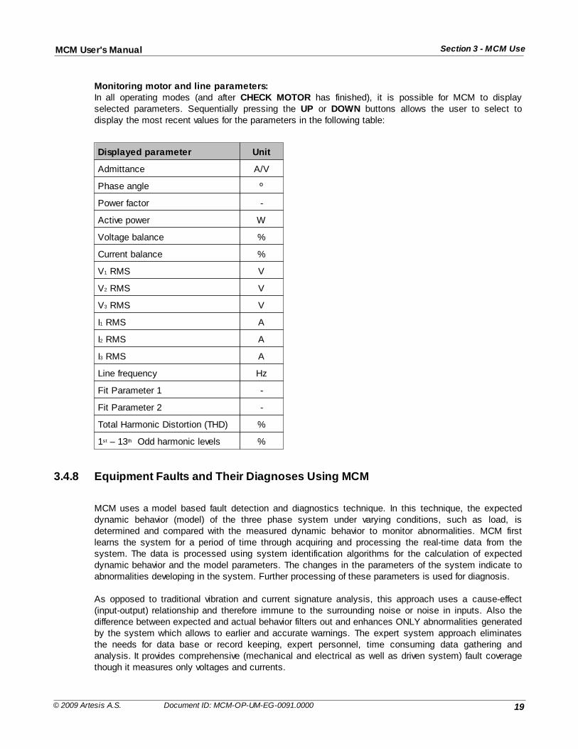
Monitoring motor and line parameters:In all operating modes (and after CHECK MOTOR has finished), it is possible for MCM to displayselected parameters. Sequentially pressing the UP or DOWN buttons allows the user to select todisplay the most recent values for the parameters in the following table:
Displayed parameter Unit
Admittance A/V
Phase angle º
Power factor -
Active power W
Voltage balance %
Current balance %
V1 RMS V
V2 RMS V
V3 RMS V
I1 RMS A
I2 RMS A
I3 RMS A
Line frequency Hz
Fit Parameter 1 -
Fit Parameter 2 -
Total Harmonic Distortion (THD) %
1st – 13th Odd harmonic levels %
3.4.8 Equipment Faults and Their Diagnoses Using MCM
MCM uses a model based fault detection and diagnostics technique. In this technique, the expecteddynamic behavior (model) of the three phase system under varying conditions, such as load, isdetermined and compared with the measured dynamic behavior to monitor abnormalities. MCM firstlearns the system for a period of time through acquiring and processing the real-time data from thesystem. The data is processed using system identification algorithms for the calculation of expecteddynamic behavior and the model parameters. The changes in the parameters of the system indicate toabnormalities developing in the system. Further processing of these parameters is used for diagnosis.
As opposed to traditional vibration and current signature analysis, this approach uses a cause-effect(input-output) relationship and therefore immune to the surrounding noise or noise in inputs. Also thedifference between expected and actual behavior filters out and enhances ONLY abnormalities generatedby the system which allows to earlier and accurate warnings. The expert system approach eliminatesthe needs for data base or record keeping, expert personnel, time consuming data gathering andanalysis. It provides comprehensive (mechanical and electrical as well as driven system) fault coveragethough it measures only voltages and currents.
20
Section 3 - MCM UseMCM User's Manual
© 2009 Artesis A.S. Document ID: MCM-OP-UM-EG-0091.0000
MCM uses the electric motor of the equipment as a sensor. Therefore, any fault of the equipment thataffects the motor or the three phase system is also observed by MCM.
MCM first learns the motor-based system for a period of time by acquiring and processing the motordata. The results of the processed data are stored in its internal database and a reference model isestablished. This reference model basically consists of model parameters, their mean values and theirstandard deviations. While monitoring, MCM processes the acquired motor data and compares theresults to the data stored in its internal database. If the results obtained from the acquired data aresignificantly different from the reference model, MCM indicates a fault level. The level is determined bytaking into account the magnitude and the time duration of the difference. In total, MCM monitors andcompares 22 different parameters (model parameters). These parameters are classified into threegroups, electrical parameters, mechanical parameters and fit parameters. These are explained in detailin the following sections.
1. Electrical Parameters
There are 8 parameters in the first group which are called electrical parameters. These are the networkequivalent parameters and are correlated to the physical parameter of the motor, like inductances,resistances, etc. They are sensitive to electrical faults developing in the motor. MCM evaluates andanalyzes the differences between the model parameters at any instant and the average value of thesame parameters that are obtained during the learn stage. These differences are normalized with respectto their standard deviations obtained during the learn stage. Hence the values indicate the number ofstandard deviations they are away from the average values obtained during the learn stage. If theyexceed threshold values, than an alarm is given. The changes in their values are associated with thefaults that are developing in the system. As an example an isolation problem in winding will affect theparameters associated with resistances. Their change will allow MCM to detect the isolation problem atan early stage. Though they are primarily used to detect electrical problems, they also can indicatemechanical problems as well. As an example an imbalance or gear problem would cause dynamiceccentricity in the air gap. This eccentricity will cause a change in the induction parameters andtherefore in the model parameters. By monitoring the changes in these model parameters imbalance canbe detected at an early stage. This eccentricity eventually affects bearing and it will also eventuallydamage the bearing. Therefore its detection at an early stage can prevent further damages
The electrical parameters are further classified in two groups, E1 (internal) and E2 (external)parameters. Electrical parameters 1-4 (E1) indicate problems associated with rotor, stator, winding etc.while 5-8 (E2) indicate electrical supply problems such as voltage imbalance, isolation problem ofcabling, capacitor, motor connector, terminal slackness, defective contactors etc.
2. Mechanical Parameters
The parameters in the second group are sensitive to mechanical faults such as load imbalance,misalignment, coupling and bearing problems. They are called Mechanical Parameters 1-12. Theseparameters are obtained from the frequency spectrum of the electrical signals by extracting informationfrom the line current and voltage supplied to a motor. The variances in the stator-rotor air gap arereflected back in the motor’s current through the air gap flux affecting the counter electromotive force.Therefore current carries information related to both mechanical and electrical faults. Hence faults willexhibit a change in the frequency spectrum of the current in specific frequencies.
MCM uses the power spectral density (psd) obtained from the differences between the expected currentobtained from the model and the actual current. These differences include only abnormalities generatedby the motor. Therefore, they are immune to the noise or harmonics present in the supply voltages. Themechanical parameters indicate the power level of the difference between measured and estimatedcurrent at frequencies they occur in terms of number of standard deviations. If they exceed the threshold
21
Section 3 - MCM UseMCM User's Manual
© 2009 Artesis A.S. Document ID: MCM-OP-UM-EG-0091.0000
value, which is 8, an abnormality is indicated.
The mechanical parameters (M1-M12) correspond to the 12 maximum values obtained in the frequencyspectrum. These parameters are also used for diagnoses. The frequencies they occur indicate the typeof fault, i.e., an imbalance, loose foundation, oil whip, fan blades, inner or outer race of bearing etc.These parameters provided to the user for trending and diagnostic purposes.
3.4.9 Interpreting MCM fault indications
3.4.9.1 MCM status values
MCM employs two different measures for calculating the motor status: Motor Status 1 and Motor Status2. In addition to these, MCM also monitors load and line changes and summarizes the results of thismonitoring via the Load line status parameter. Motor Status 1 monitors the maxima of each of the threegroups of parameters introduced in the previous section, over a window (with a default window size of 14iterations in a monitoring mode) and compares them with four different internal thresholds calculatedfollowing the initial learning phase. Motor Status 1 takes value between 1 to 5 and is calculated asfollows:
Motor Status 2 also takes values between 1 and 5. The calculation of Motor Status 2 is based oncounting the frequency of the values of Motor Status 1, that are greater than one, and the frequencies ofany load and line changes over larger windows. Window sizes and frequency thresholds used for thecalculation of Motor Status 2 are selected so that temporary a change in Motor Status 1 does not causeany change in Motor Status 2.
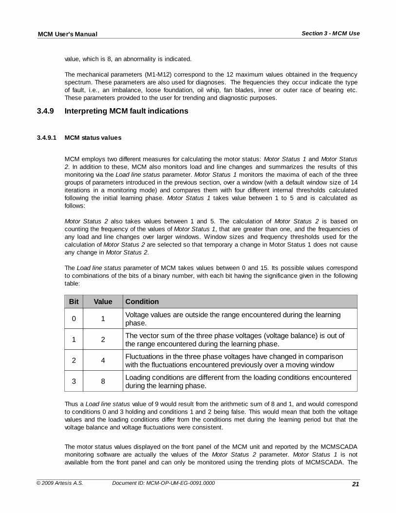
The Load line status parameter of MCM takes values between 0 and 15. Its possible values correspondto combinations of the bits of a binary number, with each bit having the significance given in the followingtable:
Bit Value Condition
0 1Voltage values are outside the range encountered during the learningphase.
1 2The vector sum of the three phase voltages (voltage balance) is out ofthe range encountered during the learning phase.
2 4Fluctuations in the three phase voltages have changed in comparisonwith the fluctuations encountered previously over a moving window
3 8Loading conditions are different from the loading conditions encounteredduring the learning phase.
Thus a Load line status value of 9 would result from the arithmetic sum of 8 and 1, and would correspondto conditions 0 and 3 holding and conditions 1 and 2 being false. This would mean that both the voltagevalues and the loading conditions differ from the conditions met during the learning period but that thevoltage balance and voltage fluctuations were consistent.
The motor status values displayed on the front panel of the MCM unit and reported by the MCMSCADAmonitoring software are actually the values of the Motor Status 2 parameter. Motor Status 1 is notavailable from the front panel and can only be monitored using the trending plots of MCMSCADA. The
22
Section 3 - MCM UseMCM User's Manual
© 2009 Artesis A.S. Document ID: MCM-OP-UM-EG-0091.0000
LED indicators on the front panel of MCM correspond to the values of Motor Status 2, starting with OK(value of 1) on the left and increasing up to Examine 2 (value of 5) on the right.
3.4.9.2 Changes in line voltages
Motor status alarms associated with the changes in the line conditions are indicated by the "WatchLine" message on the front panel, the second (3.) LED indicator being lit and Motor Status 2 having thevalue of 2. They are usually temporary in nature and generally the user does not need to take any action.However, it is recommended that when this status level occurs, the user should at least assess theextent of the change in the line conditions, as significant changes in the line voltages and currents maybe dangerous to the motor. If the line status change is persistent, the user should assess the root causeof this change. For instance, it may be due to a problem in the contactors or for inverter driven motorsthe settings of the inverter may have been changed. In any case, if the root cause cannot be remediedeasily and quickly and the new voltage supply condition presents no danger to the motor, the user hasthe option to send MCM to the UPDATE mode. This will allow MCM to learn the new voltage supplyconditions, after which the status will eventually return to normal.
3.4.9.3 Load changes
Motor status levels associated with changes in the loading conditions occur with the "Watch Load"Message on the front panel, the second (orange) LED indicator being lit, and Motor Status 2 taking avalue of 3. They are also temporary in nature but they should be treated more carefully than linechanges, as some faults developing in motor based systems can cause changes in the loadingconditions. For instance, leakages from pump seals can cause pressure drops, which will be interpretedby MCM as changes in the loading conditions. Similarly, clogging in a pipe or membrane or an increasein the friction of moving parts will be detected as changes in the apparent load. It is, therefore, importantto assess the root cause of the load change. In certain cases, (for instance, closing or opening a valve orchanging a pipe), the changes in the loading conditions are intentional and should already be known bythe user. In such cases, the user should send MCM to the UPDATE mode so that it will learn the newloading conditions. When no obvious cause can be found, it is likely that a fault is indeed developing andthe situation should be monitored more carefully.
3.4.9.4 Error messages
Unlike alarms, errors refer to failures of the MCM hardware and software rather than the monitored motor.When MCM discovers an error condition it makes several attempts to recover, and only if these attemptsare unsuccessful is an error message generated. All errors stop MCM from functioning and must becleared before proceeding further. Errors are indicative of a serious problem within MCM and their sourceshould always be investigated. An error indication consists of two parts: Firstly the displayed errorstring; and secondly the associated error number. When reporting device malfunctions, please be sureto include both the message and its associated number. Please refer to the appendix for a full list oferror messages.
Viewing error messages and numbers:
MCM indicates an error to the user by the string Error on the first line of the display followed by the errorstring on the lower line. Pressing the RIGHT or LEFT buttons will display the error number.
Canceling errors and Performing a master reset:
Pressing the CLEAR button will cancel the error and return to IDLE in most cases. If the error occursduring an error recovery operation it will not be possible to cancel the error in this manner but will requirea full master reset. This is accomplished by holding down the LEFT button, whilst simultaneously either
23
Section 3 - MCM UseMCM User's Manual
© 2009 Artesis A.S. Document ID: MCM-OP-UM-EG-0091.0000
switching on the device power or pressing and releasing the reset button at the rear of the device. Notethat the unit must be in the IDLE state before removing the power or pressing the reset button or thisprocedure will not work. The button must remain held down for at least four seconds until the message:
"Press Enter for general reset"
appears on the display. At this point ENTER should be pressed to perform the reset. If this does notclear the error, it is likely that the MCM device is experiencing a hardware fault and that the unit shouldbe returned for servicing.
Please note that performing a hardware reset in this manner resets all settings to the factorydefaults and all previously saved information will be lost. This includes all learning mode andEdit Settings data, so a hardware reset should be used only as a last resort.
3.4.9.5 Using the relay output
MCM is equipped with two connections on the rear panel internally connected to a low power, normallyopen relay. Closure conditions of the relay can be programmed from
MENU: Edit Settings / Password / Run settings / Relay Threshold
and selecting the desired fault level. During MONITOR, IMPROVE and UPDATE, the relay will becomeactive anytime the fault level rises above the selected relay level, and the following message will bedisplayed:
"Relay active"
When the relay is active and the previous message displayed, pressing the LEFT or RIGHT buttonscycles through the messages:
"Acknowledge""Reset relay"
Pressing the CLEAR button while either of these messages is displayed deactivates the relay. SelectingAcknowledge will cause the relay to activate again only when the motor status exceeds the current valuewhilst Reset relay will allow the relay to activate again when the same preset conditions are next met,possibly as soon as the next data cycle.
Relay output absolute maximum ratings
Current (A) Voltage (V)
0.6 110 (AC)
2.0 30 (DC)
24
Section 3 - MCM UseMCM User's Manual
© 2009 Artesis A.S. Document ID: MCM-OP-UM-EG-0091.0000
Relay output states
StateRelay Contacts
NO COM NC COM
Relay active Closed Open
Relay inactive Open Closed
3.4.9.6 Connecting to the serial port
MCM can be connected to a PLC or other monitoring system such as MCMSCADA via the RS485 porton the rear of the device. Artesis A.S. makes available its proprietary protocol on request in documentMCM-OP-SI-EG-0002 entitled MCM System Communications Protocol Document for End Users. Pleasecontact Artesis A.S. to obtain this document.
RS 422 port connections
Pin Description Notes
1 Receive A Rx+ For 2-wires connect to Tx+
2 Receive B Rx- For 2-wires connect to Tx-
3 Transmit A Tx+
4 Transmit B Tx-
5 Common 0Optional connection to localground via 100 Ω resistor
25
Section 3 - MCM UseMCM User's Manual
© 2009 Artesis A.S. Document ID: MCM-OP-UM-EG-0091.0000
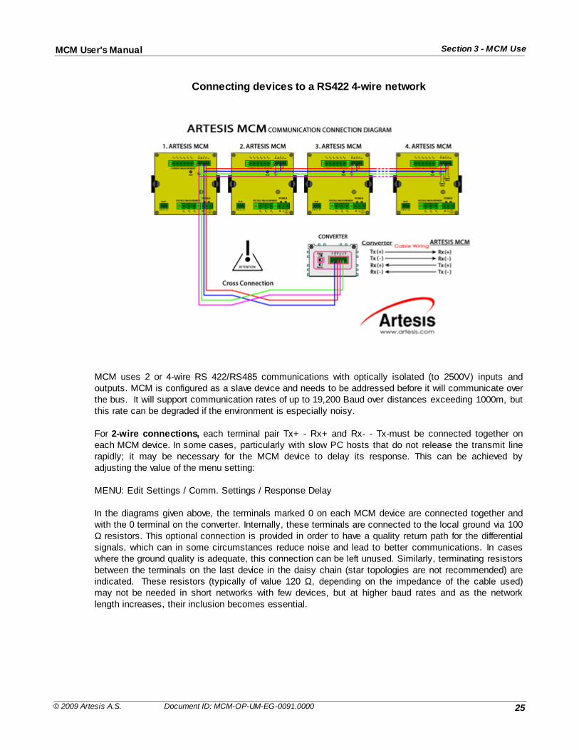
Connecting devices to a RS422 4-wire network
MCM uses 2 or 4-wire RS 422/RS485 communications with optically isolated (to 2500V) inputs andoutputs. MCM is configured as a slave device and needs to be addressed before it will communicate overthe bus. It will support communication rates of up to 19,200 Baud over distances exceeding 1000m, butthis rate can be degraded if the environment is especially noisy.
For 2-wire connections, each terminal pair Tx+ - Rx+ and Rx- - Tx-must be connected together oneach MCM device. In some cases, particularly with slow PC hosts that do not release the transmit linerapidly; it may be necessary for the MCM device to delay its response. This can be achieved byadjusting the value of the menu setting:
MENU: Edit Settings / Comm. Settings / Response Delay
In the diagrams given above, the terminals marked 0 on each MCM device are connected together andwith the 0 terminal on the converter. Internally, these terminals are connected to the local ground via 100Ω resistors. This optional connection is provided in order to have a quality return path for the differentialsignals, which can in some circumstances reduce noise and lead to better communications. In caseswhere the ground quality is adequate, this connection can be left unused. Similarly, terminating resistorsbetween the terminals on the last device in the daisy chain (star topologies are not recommended) areindicated. These resistors (typically of value 120 Ω, depending on the impedance of the cable used)may not be needed in short networks with few devices, but at higher baud rates and as the networklength increases, their inclusion becomes essential.
26
Section 3 - MCM UseMCM User's Manual
© 2009 Artesis A.S. Document ID: MCM-OP-UM-EG-0091.0000
4 Troubleshooting
4.1 Introduction
During installation and running a number of checks should be made to ascertain whether the MCM unitis performing correctly and to determine possible causes if not.
4.2 Use of the MCM Config utility
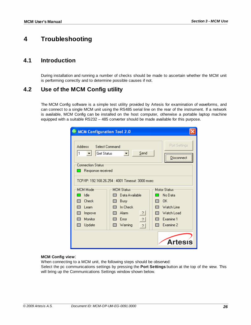
The MCM Config software is a simple test utility provided by Artesis for examination of waveforms, andcan connect to a single MCM unit using the RS485 serial line on the rear of the instrument. If a networkis available, MCM Config can be installed on the host computer, otherwise a portable laptop machineequipped with a suitable RS232 – 485 converter should be made available for this purpose.
MCM Config view:When connecting to a MCM unit, the following steps should be observed:Select the pc communications settings by pressing the Port Settings button at the top of the view. Thiswill bring up the Communications Settings window shown below.
27
Section 4 - TroubleshootingMCM User's Manual
© 2009 Artesis A.S. Document ID: MCM-OP-UM-EG-0091.0000
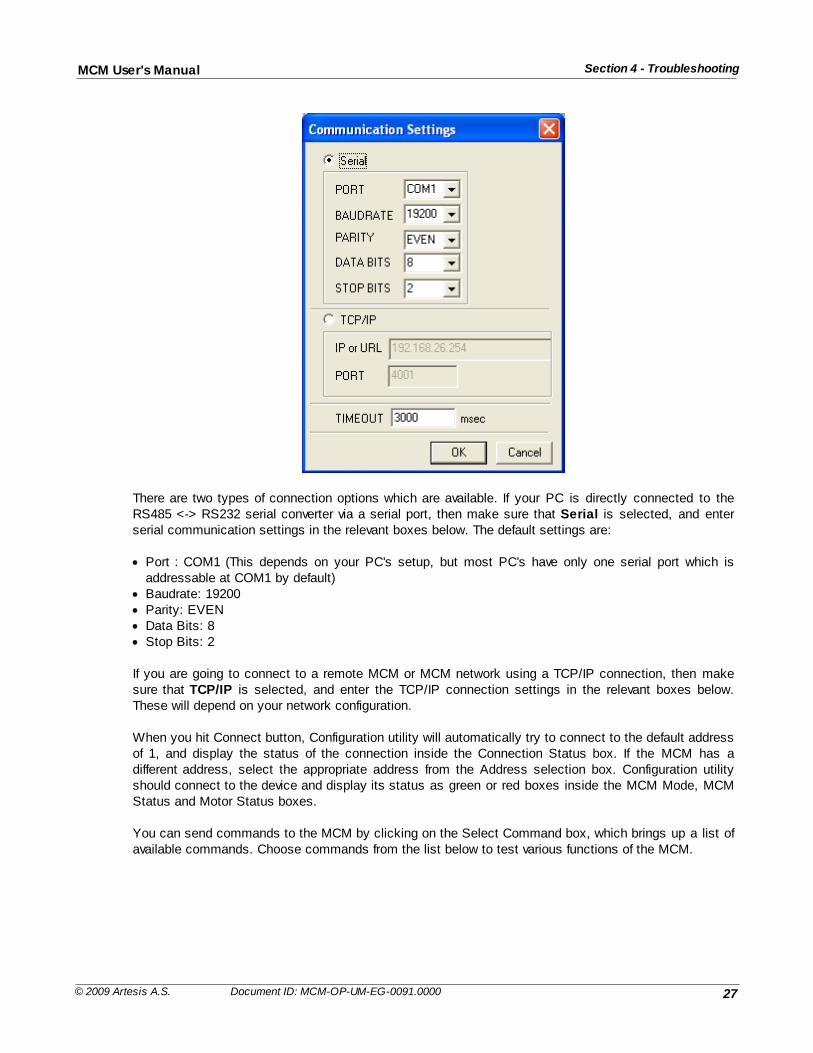
There are two types of connection options which are available. If your PC is directly connected to theRS485 <-> RS232 serial converter via a serial port, then make sure that Serial is selected, and enterserial communication settings in the relevant boxes below. The default settings are:
· Port : COM1 (This depends on your PC's setup, but most PC's have only one serial port which isaddressable at COM1 by default)
· Baudrate: 19200· Parity: EVEN· Data Bits: 8· Stop Bits: 2
If you are going to connect to a remote MCM or MCM network using a TCP/IP connection, then makesure that TCP/IP is selected, and enter the TCP/IP connection settings in the relevant boxes below.These will depend on your network configuration.
When you hit Connect button, Configuration utility will automatically try to connect to the default addressof 1, and display the status of the connection inside the Connection Status box. If the MCM has adifferent address, select the appropriate address from the Address selection box. Configuration utilityshould connect to the device and display its status as green or red boxes inside the MCM Mode, MCMStatus and Motor Status boxes.
You can send commands to the MCM by clicking on the Select Command box, which brings up a list ofavailable commands. Choose commands from the list below to test various functions of the MCM.
28
Section 4 - TroubleshootingMCM User's Manual
© 2009 Artesis A.S. Document ID: MCM-OP-UM-EG-0091.0000
Command Explanation
Get Status Updates the status information
Go Idle Sends MCM to the IDLE state
Check Sends MCM to the CHECK state
Update Sends MCM to the UPDATE state
Resume Sends MCM to the RESUME state
Run Sends MCM to the MONITOR state
Get Alarm Gets alarm information from the device
Get Error Gets error information from the device
Get Warning Gets warning information from the device
Get Version Gets MCM's version
Take Data Starts acquisition of VI data for later viewing. This also enables uploadstatus elements
Get RMS Gets RMS values from the device
Get Settings Gets MCM settings and displays all the setting values for checking &editing
Download PSD Data Gets PSD values from the device
Download VI Data Downloads previously recorded VI data for viewing. Use of Take Data isrecommended for latest VI values.
Check system response by sending a Get Status message. This is done by selecting Get Status fromthe Command selection combo box and pressing the Send Command button. If "Response Received"message dos not appear in the Connection Status box in the amount of time specified earlier as thetimeout interval, check the connections, cabling, baud rate, pc ports etc.
Waveforms of the last data acquired by MCM during data acquisition can be uploaded to the pc forinspection as follows:
Send the MCM unit to IDLE mode by selecting the Idle command from the Command Selection combo.Note that the unit always sends the current data stored in its memory so after any changes to the inputconditions it will be necessary to refresh the stored data by sending the unit to CHECK MOTOR modeusing the Check Motor command. Initiate the upload mode by sending the Take Data command. The software will wait 6 seconds and thenenable the Upload button. Press the Upload button and observe the "Data Received : " text displayedtogether with the current number of data points. The progress bar in the Upload Panel will indicate howmuch data has been downloaded. When sufficient data are available, press the Cancel Upload buttonto display the voltage and current waveforms. The view can be zoomed using the mouse to define thedesired region whilst holding down left button. Pressing the right button restores the view.
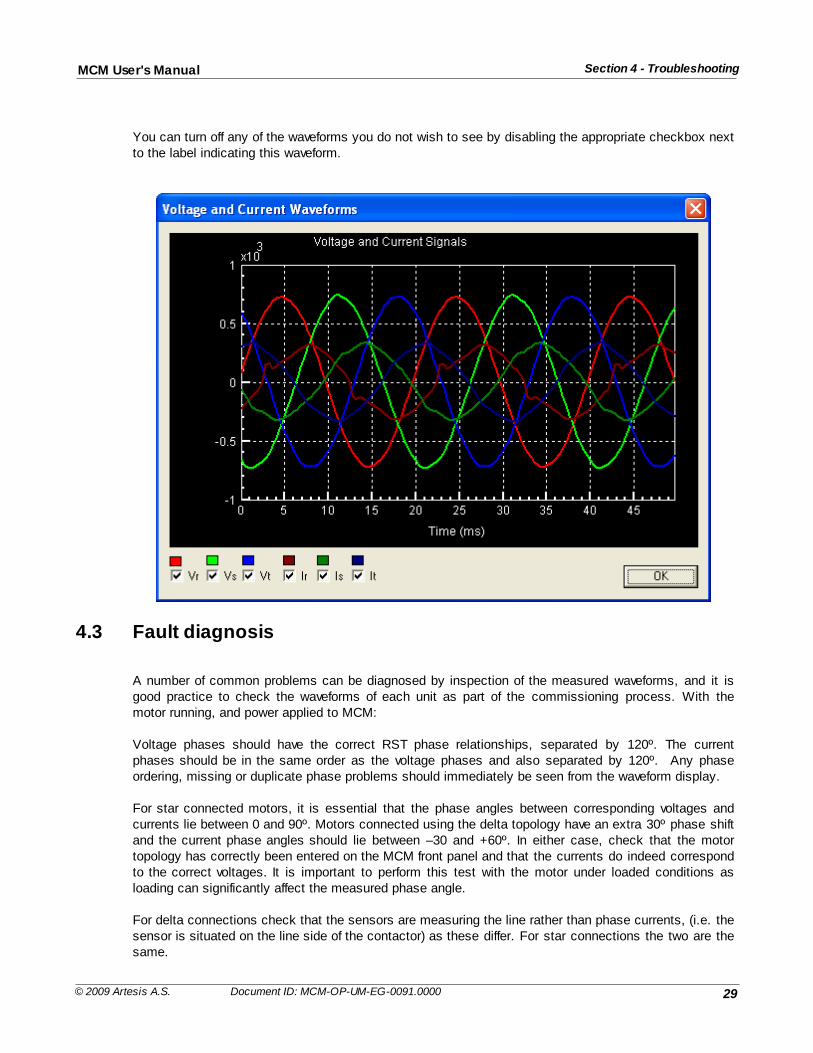
Voltage and current waveforms corresponding to the same phase are plotted in the same color. If theDisplay calibrated data checkbox is selected, the data are scaled according to the device calibration.Deselecting this box is sometimes useful to view both the voltage and current waveforms together. Thefollowing waveforms are scaled.
29
Section 4 - TroubleshootingMCM User's Manual
© 2009 Artesis A.S. Document ID: MCM-OP-UM-EG-0091.0000
You can turn off any of the waveforms you do not wish to see by disabling the appropriate checkbox nextto the label indicating this waveform.
4.3 Fault diagnosis
A number of common problems can be diagnosed by inspection of the measured waveforms, and it isgood practice to check the waveforms of each unit as part of the commissioning process. With themotor running, and power applied to MCM:
Voltage phases should have the correct RST phase relationships, separated by 120º. The currentphases should be in the same order as the voltage phases and also separated by 120º. Any phaseordering, missing or duplicate phase problems should immediately be seen from the waveform display.
For star connected motors, it is essential that the phase angles between corresponding voltages andcurrents lie between 0 and 90º. Motors connected using the delta topology have an extra 30º phase shiftand the current phase angles should lie between –30 and +60º. In either case, check that the motortopology has correctly been entered on the MCM front panel and that the currents do indeed correspondto the correct voltages. It is important to perform this test with the motor under loaded conditions asloading can significantly affect the measured phase angle.
For delta connections check that the sensors are measuring the line rather than phase currents, (i.e. thesensor is situated on the line side of the contactor) as these differ. For star connections the two are thesame.
30
Section 4 - TroubleshootingMCM User's Manual
© 2009 Artesis A.S. Document ID: MCM-OP-UM-EG-0091.0000
If the amplitude of the R phase current waveform varies excessively, MCM will not be able to find stabledata and will give the unstable line alarm. If the problem lies with the input signals, it should beimmediately obvious by inspecting the displayed waveform. In the case of excessive variation of the Rphase current amplitude, the Current Instability threshold should be incremented from its default value of15% in steps of 5% up to a maximum value of 50% using the MCM front panel. If the variation exceedsthis level, please contact Artesis.
All phases should be checked for correct, clean, zero crossing. If a waveform appears to be regular andsinusoidal over consecutive half periods, but does not cross through zero, it is likely that the zerocrossing detection hardware is defective and the unit should be replaced. If however, the waveform isirregular the problem could lie with the sensors. In this case check all cabling and power supplyconnections. If these are satisfactory, return the unit if the problem lies with a voltage channel. Forcurrent channels, try replacing or swapping the sensor with another one. If the new sensor does not workthe problem is internal to the MCM unit and it should be returned to Artesis.
If any phase has a marked difference in amplitude to other similar phases, the calibration constant forthat phase should be checked. If no external sensor is attached (i.e. for low voltage motors) thecalibration constant should be 1. If the calibration is correct, the sensor may be defective and should bechanged.
Check the current balance levels using the MCM front panel. A value below 15% is acceptable, butabove 15%, the Total Harmonic Distortion (THD) on all current phases should be checked. Normal levelsfor THD can be up to 6% depending on conditions. For values higher than this level check whether thedistortion originates from the motor or the line, by measuring the THD present at other motors connectedto the same supply. If the same level for THD is measured at other motors, the line supply is suspectand should be investigated as high levels can damage motors in the long term. Otherwise, the motor isprobably already damaged in some way and should be investigated.
Check the voltage imbalance levels using the front panel. A value below 5% is deemed satisfactory.Above this level, check the THD levels on each voltage phase. Levels above 5% should be investigated.The ability of MCM to detect faults will be reduced as voltage imbalance increases.
Check that all waveforms disappear when power is removed from the motor.
4.4 Servicing
MCM contains no user serviceable parts and must be returned to either Artesis A.S. or its designatedagents if repair is needed.
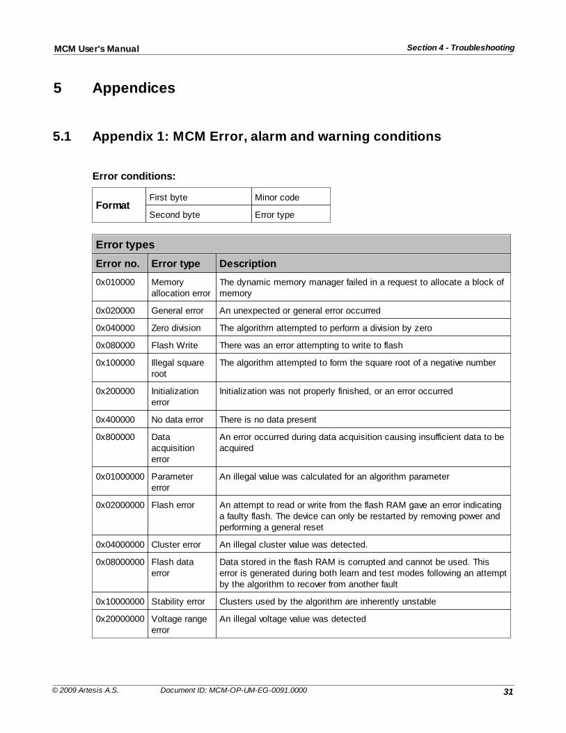
31
Section 4 - TroubleshootingMCM User's Manual
© 2009 Artesis A.S. Document ID: MCM-OP-UM-EG-0091.0000
5 Appendices
5.1 Appendix 1: MCM Error, alarm and warning conditions
Error conditions:
FormatFirst byte Minor code
Second byte Error type
Error types
Error no. Error type Description
0x010000 Memoryallocation error
The dynamic memory manager failed in a request to allocate a block ofmemory
0x020000 General error An unexpected or general error occurred
0x040000 Zero division The algorithm attempted to perform a division by zero
0x080000 Flash Write There was an error attempting to write to flash
0x100000 Illegal squareroot
The algorithm attempted to form the square root of a negative number
0x200000 Initializationerror
Initialization was not properly finished, or an error occurred
0x400000 No data error There is no data present
0x800000 Dataacquisitionerror
An error occurred during data acquisition causing insufficient data to beacquired
0x01000000 Parametererror
An illegal value was calculated for an algorithm parameter
0x02000000 Flash error An attempt to read or write from the flash RAM gave an error indicatinga faulty flash. The device can only be restarted by removing power andperforming a general reset
0x04000000 Cluster error An illegal cluster value was detected.
0x08000000 Flash dataerror
Data stored in the flash RAM is corrupted and cannot be used. Thiserror is generated during both learn and test modes following an attemptby the algorithm to recover from another fault
0x10000000 Stability error Clusters used by the algorithm are inherently unstable
0x20000000 Voltage rangeerror
An illegal voltage value was detected
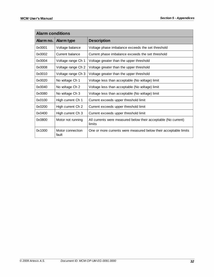
32
Section 5 - AppendicesMCM User's Manual
© 2009 Artesis A.S. Document ID: MCM-OP-UM-EG-0091.0000
Alarm conditions
Alarm no. Alarm type Description
0x0001 Voltage balance Voltage phase imbalance exceeds the set threshold
0x0002 Current balance Current phase imbalance exceeds the set threshold
0x0004 Voltage range Ch 1 Voltage greater than the upper threshold
0x0008 Voltage range Ch 2 Voltage greater than the upper threshold
0x0010 Voltage range Ch 3 Voltage greater than the upper threshold
0x0020 No voltage Ch 1 Voltage less than acceptable (No voltage) limit
0x0040 No voltage Ch 2 Voltage less than acceptable (No voltage) limit
0x0080 No voltage Ch 3 Voltage less than acceptable (No voltage) limit
0x0100 High current Ch 1 Current exceeds upper threshold limit
0x0200 High current Ch 2 Current exceeds upper threshold limit
0x0400 High current Ch 3 Current exceeds upper threshold limit
0x0800 Motor not running All currents were measured below their acceptable (No current)limits
0x1000 Motor connectionfault
One or more currents were measured below their acceptable limits
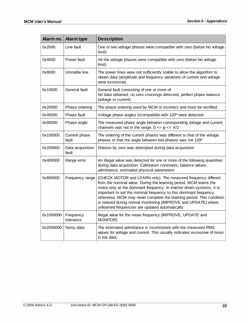
33
Section 5 - AppendicesMCM User's Manual
© 2009 Artesis A.S. Document ID: MCM-OP-UM-EG-0091.0000
Alarm no. Alarm type Description
0x2000 Line fault One or two voltage phases were compatible with zero (below No voltagelimit)
0x4000 Power fault All the voltage phases were compatible with zero (below No voltagelimit)
0x8000 Unstable line The power lines were not sufficiently stable to allow the algorithm toobtain data (amplitude and frequency variations of current and voltagewere excessive)
0x10000 General fault General fault consisting of one or more of:No data obtained, no zero crossings detected, perfect phase balance(voltage or current)
0x20000 Phase ordering The phase ordering used by MCM is incorrect and must be rectified.
0x40000 Phase fault Voltage phase angles incompatible with 120º were detected
0x80000 Phase angle The measured phase angle between corresponding voltage and currentchannels was not in the range: 0 <= φ <= π /2
0x100000 Current phasefault
The ordering of the current phases was different to that of the voltagephases or that the angle between two phases was not 120º
0x200000 Data acquisitionfault
Division by zero was attempted during data acquisition
0x400000 Range error An illegal value was detected for one or more of the following quantitiesduring data acquisition: Calibration constants, balance values,admittance, estimated physical parameters
0x800000 Frequency range (CHECK MOTOR and LEARN only). The measured frequency differedfrom the nominal value. During the learning period, MCM learns themotor only at the dominant frequency. In inverter driven systems, it isimportant to set the nominal frequency to this dominant frequencyotherwise, MCM may never complete the learning period. This conditionis relaxed during normal monitoring (IMPROVE and UPDATE) whereunlearned frequencies are updated automatically
0x1000000 Frequencytolerance
Illegal value for the mean frequency (IMPROVE, UPDATE andMONITOR)
0x2000000 Noisy data The estimated admittance is inconsistent with the measured RMSvalues for voltage and current. This usually indicates excessive of noisein the data
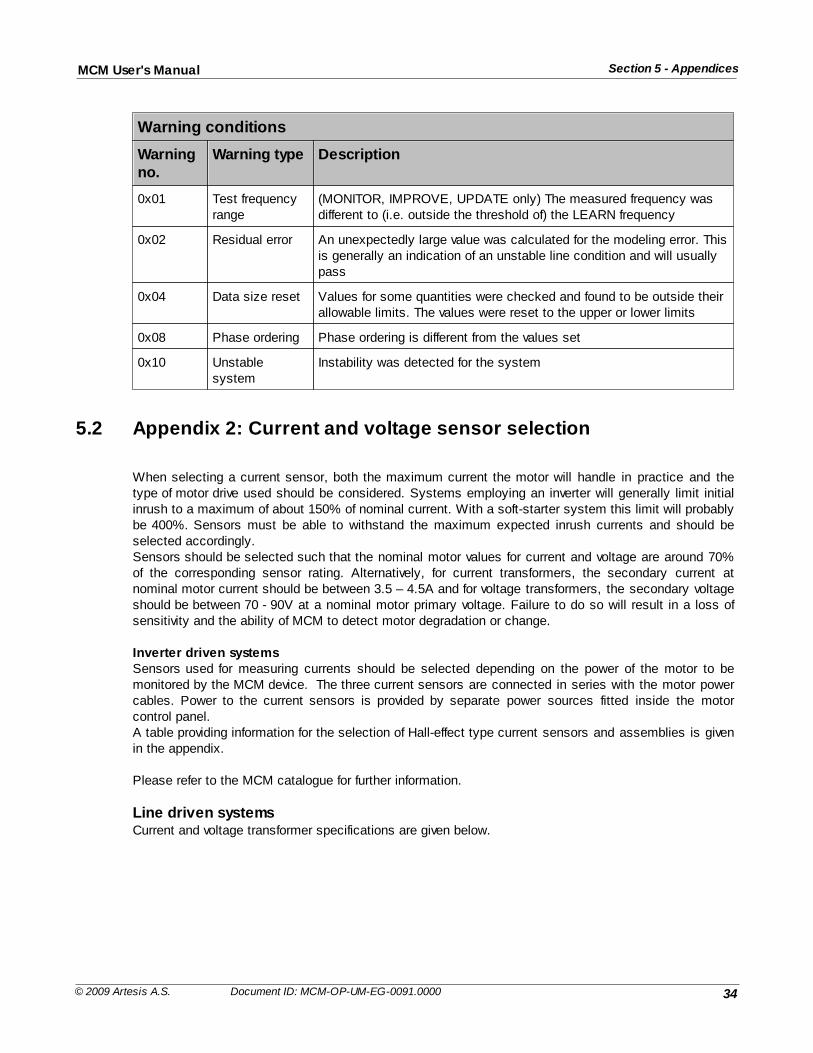
34
Section 5 - AppendicesMCM User's Manual
© 2009 Artesis A.S. Document ID: MCM-OP-UM-EG-0091.0000
Warning conditions
Warningno.
Warning type Description
0x01 Test frequencyrange
(MONITOR, IMPROVE, UPDATE only) The measured frequency wasdifferent to (i.e. outside the threshold of) the LEARN frequency
0x02 Residual error An unexpectedly large value was calculated for the modeling error. Thisis generally an indication of an unstable line condition and will usuallypass
0x04 Data size reset Values for some quantities were checked and found to be outside theirallowable limits. The values were reset to the upper or lower limits
0x08 Phase ordering Phase ordering is different from the values set
0x10 Unstablesystem
Instability was detected for the system
5.2 Appendix 2: Current and voltage sensor selection
When selecting a current sensor, both the maximum current the motor will handle in practice and thetype of motor drive used should be considered. Systems employing an inverter will generally limit initialinrush to a maximum of about 150% of nominal current. With a soft-starter system this limit will probablybe 400%. Sensors must be able to withstand the maximum expected inrush currents and should beselected accordingly. Sensors should be selected such that the nominal motor values for current and voltage are around 70%of the corresponding sensor rating. Alternatively, for current transformers, the secondary current atnominal motor current should be between 3.5 – 4.5A and for voltage transformers, the secondary voltageshould be between 70 - 90V at a nominal motor primary voltage. Failure to do so will result in a loss ofsensitivity and the ability of MCM to detect motor degradation or change.
Inverter driven systemsSensors used for measuring currents should be selected depending on the power of the motor to bemonitored by the MCM device. The three current sensors are connected in series with the motor powercables. Power to the current sensors is provided by separate power sources fitted inside the motorcontrol panel. A table providing information for the selection of Hall-effect type current sensors and assemblies is givenin the appendix.
Please refer to the MCM catalogue for further information.
Line driven systemsCurrent and voltage transformer specifications are given below.
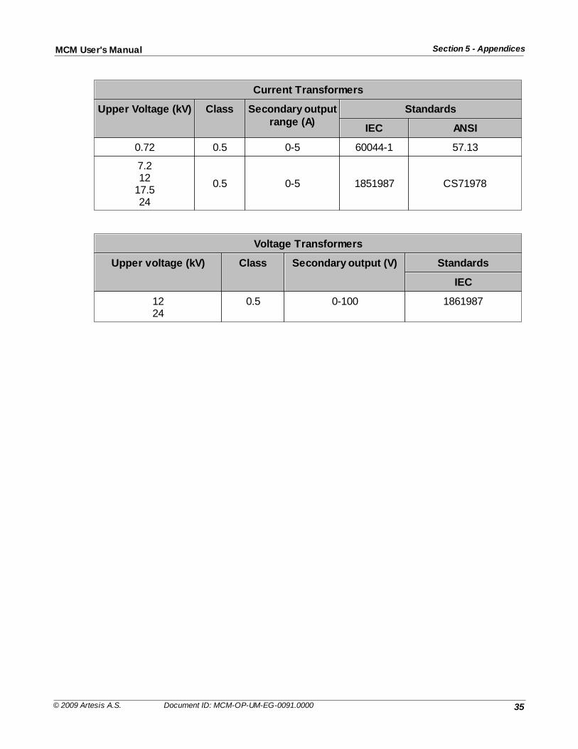
35
Section 5 - AppendicesMCM User's Manual
© 2009 Artesis A.S. Document ID: MCM-OP-UM-EG-0091.0000
Current Transformers
Upper Voltage (kV) Class Secondary outputrange (A)
Standards
IEC ANSI
0.72 0.5 0-5 60044-1 57.13
7.212
17.524
0.5 0-5 1851987 CS71978
Voltage Transformers
Upper voltage (kV) Class Secondary output (V) Standards
IEC
1224
0.5 0-100 1861987
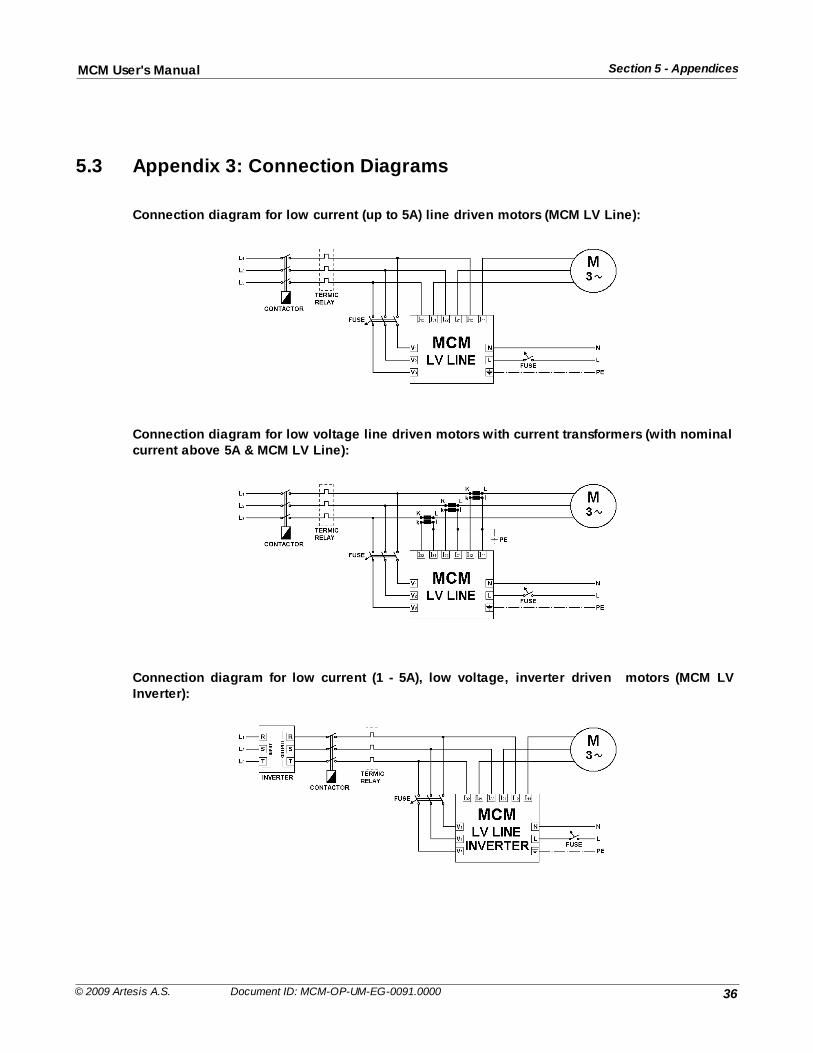
36
Section 5 - AppendicesMCM User's Manual
© 2009 Artesis A.S. Document ID: MCM-OP-UM-EG-0091.0000
5.3 Appendix 3: Connection Diagrams
Connection diagram for low current (up to 5A) line driven motors (MCM LV Line):
Connection diagram for low voltage line driven motors with current transformers (with nominalcurrent above 5A & MCM LV Line):
Connection diagram for low current (1 - 5A), low voltage, inverter driven motors (MCM LVInverter):
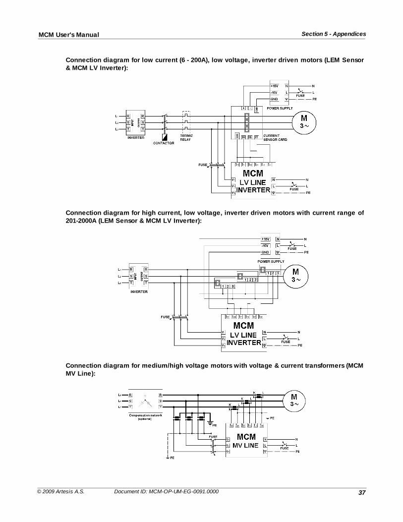
37
Section 5 - AppendicesMCM User's Manual
© 2009 Artesis A.S. Document ID: MCM-OP-UM-EG-0091.0000
Connection diagram for low current (6 - 200A), low voltage, inverter driven motors (LEM Sensor& MCM LV Inverter):
Connection diagram for high current, low voltage, inverter driven motors with current range of201-2000A (LEM Sensor & MCM LV Inverter):
Connection diagram for medium/high voltage motors with voltage & current transformers (MCMMV Line):
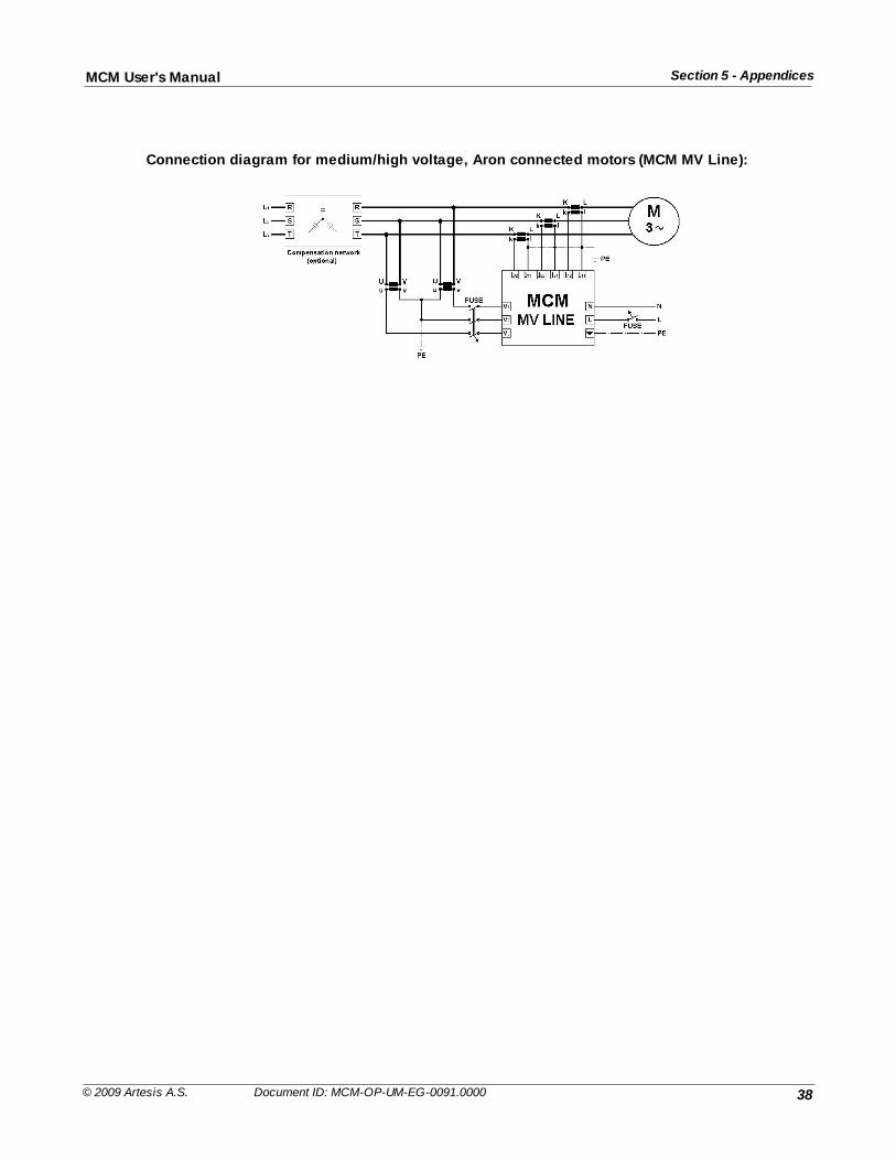
38
Section 5 - AppendicesMCM User's Manual
© 2009 Artesis A.S. Document ID: MCM-OP-UM-EG-0091.0000
Connection diagram for medium/high voltage, Aron connected motors (MCM MV Line):
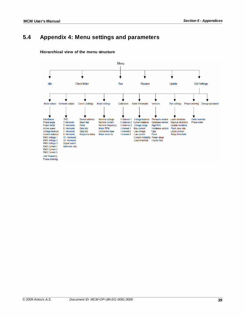
39
Section 5 - AppendicesMCM User's Manual
© 2009 Artesis A.S. Document ID: MCM-OP-UM-EG-0091.0000
5.4 Appendix 4: Menu settings and parameters
Hierarchical view of the menu structure
40
Section 5 - AppendicesMCM User's Manual
© 2009 Artesis A.S. Document ID: MCM-OP-UM-EG-0091.0000
5.5 Appendix 5: Edit Settings Menu items
EditSettingsMenugroup
Sub menuitems
Description Type Range Defaultvalue
Motor values Admittance Ratio of RMS current to voltage Displayonly
N/A N/A
Phaseangle
Angle between V1 and I1 channels in degrees(φ)
Displayonly
N/A N/A
Power factor Cosine of phase angle between V1 and I1channels (Cos φ)
Displayonly
N/A N/A
Active power V.I. Cos φ Displayonly
N/A N/A
Voltagebalance %
Defined as |v1 +v2+v3| / (|v1|+|v2|+|v3|)A measure of imbalance between phases ( 0 =perfect balance)
Displayonly
N/A N/A
Currentbalance %
Defined as |I1 +I2+I3| / (|I1|+|I2|+|I3|). A measure of imbalance between phases ( 0 =perfect balance)
Displayonly
N/A N/A
RMSVoltage 1
Measured RMS quantities for each input channel Displayonly
N/A N/A
RMSVoltage 2
Displayonly
N/A N/A
RMSVoltage 3
Displayonly
N/A N/A
RMSCurrent 1
Displayonly
N/A N/A
RMSCurrent 2
Displayonly
N/A N/A
RMSCurrent 3
Displayonly
N/A N/A
Linefrequency
Measured line frequency Displayonly
N/A N/A
Phaseordering
The observed order of the connections relative tothe V1 input channelLower case voltage, upper case current.
Displayonly
N/A N/A
Harmonicvalues
THD % Total harmonic distortion of the selected inputchannel
Displayonly
N/A N/A
1st
Harmonic %
Harmonic contents of the selected input channel Displayonly
N/A N/A
3rd Displayonly
N/A N/A
41
Section 5 - AppendicesMCM User's Manual
© 2009 Artesis A.S. Document ID: MCM-OP-UM-EG-0091.0000
EditSettingsMenugroup
Sub menuitems
Description Type Range Defaultvalue
Harmonic %
5th
Harmonic %
Displayonly
N/A N/A
7th
Harmonic %
Displayonly
N/A N/A
9th
Harmonic %
Displayonly
N/A N/A
11th
Harmonic %
Displayonly
N/A N/A
13th
Harmonic %
Displayonly
N/A N/A
Signalselect
The input channel selected for harmonicmeasurements
Edit/Display
V1/V2/V3I1/I2/I3
I1
Harmoniccalc
Switch harmonic calculations On/Off Edit/Display
ON/OFF ON
Comm.settings
Deviceaddress
Networking address Edit/Display
1-255 0
Baud rate Communications bit transfer speed Edit/Display
300-38400
19200
Parity Parity check Edit/Display
Even/Odd Even
Data bits Number of bits containing data Edit/Display
7/8/9 8
Stop bits Number of bits indicating end of transmittedframe
Edit/Display
1/2 2
Responsedelay
Delay (in ms) before MCM will respond to aninput command.
Edit/Display
0 – 9 0
Motorsettings
Nominalvoltage
Nominal motor phase – neutral working voltage Edit/Display
0.1 –50000VAC
230VAC
Nominalcurrent
Nominal motor working current Edit/Display
0.1- 3000A
300 A
Nominalfrequency
Nominal line frequency or most common inverteroperating frequency
Edit/Display
20 – 100Hz
50 Hz
NominalRPM
Nominal angular speed of the motor Edit/Display
200 –3000 rpm
1500
Connectiontype
Motor connection type under normal runningconditions
Edit/Display
Star/Delta Star
Motor serial Optional identifier Edit/ - m000
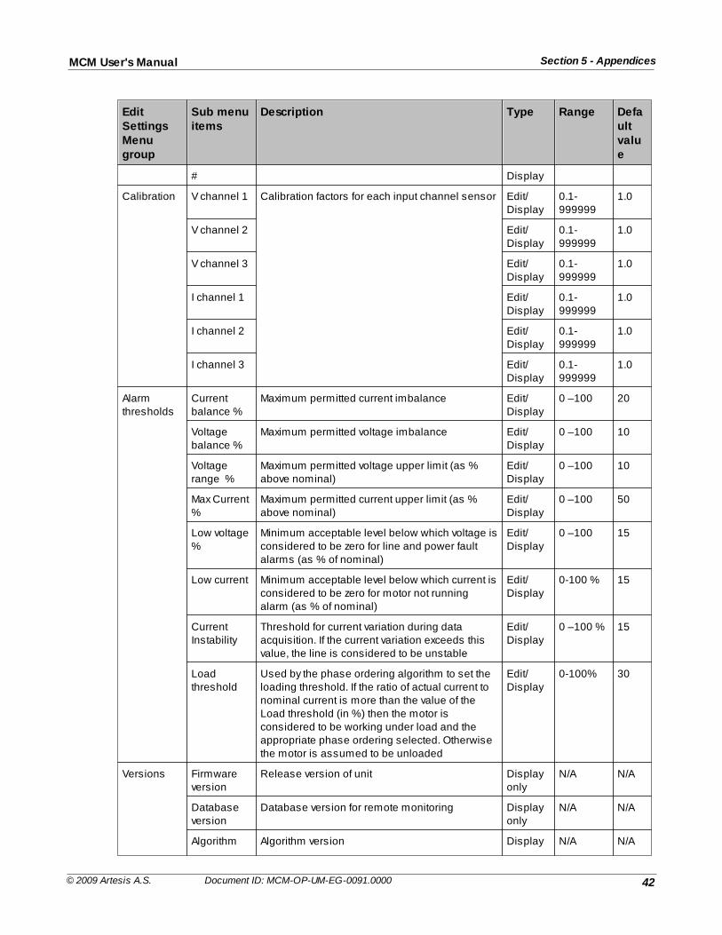
42
Section 5 - AppendicesMCM User's Manual
© 2009 Artesis A.S. Document ID: MCM-OP-UM-EG-0091.0000
EditSettingsMenugroup
Sub menuitems
Description Type Range Defaultvalue
# Display
Calibration V channel 1 Calibration factors for each input channel sensor Edit/Display
0.1-999999
1.0
V channel 2 Edit/Display
0.1-999999
1.0
V channel 3 Edit/Display
0.1-999999
1.0
I channel 1 Edit/Display
0.1-999999
1.0
I channel 2 Edit/Display
0.1-999999
1.0
I channel 3 Edit/Display
0.1-999999
1.0
Alarmthresholds
Currentbalance %
Maximum permitted current imbalance Edit/Display
0 –100 20
Voltagebalance %
Maximum permitted voltage imbalance Edit/Display
0 –100 10
Voltagerange %
Maximum permitted voltage upper limit (as %above nominal)
Edit/Display
0 –100 10
Max Current%
Maximum permitted current upper limit (as %above nominal)
Edit/Display
0 –100 50
Low voltage%
Minimum acceptable level below which voltage isconsidered to be zero for line and power faultalarms (as % of nominal)
Edit/Display
0 –100 15
Low current Minimum acceptable level below which current isconsidered to be zero for motor not runningalarm (as % of nominal)
Edit/Display
0-100 % 15
CurrentInstability
Threshold for current variation during dataacquisition. If the current variation exceeds thisvalue, the line is considered to be unstable
Edit/Display
0 –100 % 15
Loadthreshold
Used by the phase ordering algorithm to set theloading threshold. If the ratio of actual current tonominal current is more than the value of theLoad threshold (in %) then the motor isconsidered to be working under load and theappropriate phase ordering selected. Otherwisethe motor is assumed to be unloaded
Edit/Display
0-100% 30
Versions Firmwareversion
Release version of unit Displayonly
N/A N/A
Databaseversion
Database version for remote monitoring Displayonly
N/A N/A
Algorithm Algorithm version Display N/A N/A
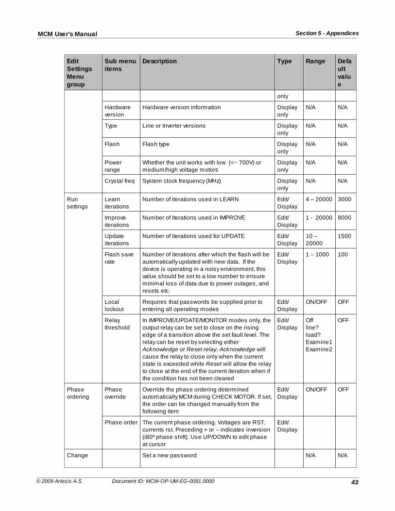
43
Section 5 - AppendicesMCM User's Manual
© 2009 Artesis A.S. Document ID: MCM-OP-UM-EG-0091.0000
EditSettingsMenugroup
Sub menuitems
Description Type Range Defaultvalue
only
Hardwareversion
Hardware version information Displayonly
N/A N/A
Type Line or Inverter versions Displayonly
N/A N/A
Flash Flash type Displayonly
N/A N/A
Powerrange
Whether the unit works with low (<~ 700V) ormedium/high voltage motors
Displayonly
N/A N/A
Crystal freq System clock frequency (MHz) Displayonly
N/A N/A
Runsettings
Learniterations
Number of iterations used in LEARN Edit/Display
4 – 20000 3000
Improveiterations
Number of iterations used in IMPROVE Edit/Display
1 - 20000 8000
Updateiterations
Number of iterations used for UPDATE Edit/Display
10 –20000
1500
Flash saverate
Number of iterations after which the flash will beautomatically updated with new data. If thedevice is operating in a noisy environment, thisvalue should be set to a low number to ensureminimal loss of data due to power outages, andresets etc.
Edit/Display
1 – 1000 100
Locallockout
Requires that passwords be supplied prior toentering all operating modes
Edit/Display
ON/OFF OFF
Relaythreshold
In IMPROVE/UPDATE/MONITOR modes only, theoutput relay can be set to close on the risingedge of a transition above the set fault level. Therelay can be reset by selecting either Acknowledge or Reset relay. Acknowledge willcause the relay to close only when the currentstate is exceeded while Reset will allow the relayto close at the end of the current iteration when ifthe condition has not been cleared
Edit/Display
Offline?load?Examine1Examine2
OFF
Phaseordering
Phaseoverride
Override the phase ordering determinedautomatically MCM during CHECK MOTOR. If set,the order can be changed manually from thefollowing item
Edit/Display
ON/OFF OFF
Phase order The current phase ordering. Voltages are RST,currents rst. Preceding + or – indicates inversion(i80º phase shift). Use UP/DOWN to edit phaseat cursor
Edit/Display
Change Set a new password N/A N/A
44
Section 5 - AppendicesMCM User's Manual
© 2009 Artesis A.S. Document ID: MCM-OP-UM-EG-0091.0000
EditSettingsMenugroup
Sub menuitems
Description Type Range Defaultvalue
password
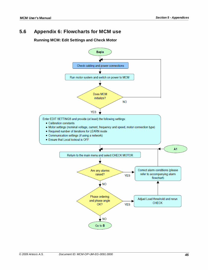
45
Section 5 - AppendicesMCM User's Manual
© 2009 Artesis A.S. Document ID: MCM-OP-UM-EG-0091.0000
5.6 Appendix 6: Flowcharts for MCM use
Running MCM: Edit Settings and Check Motor
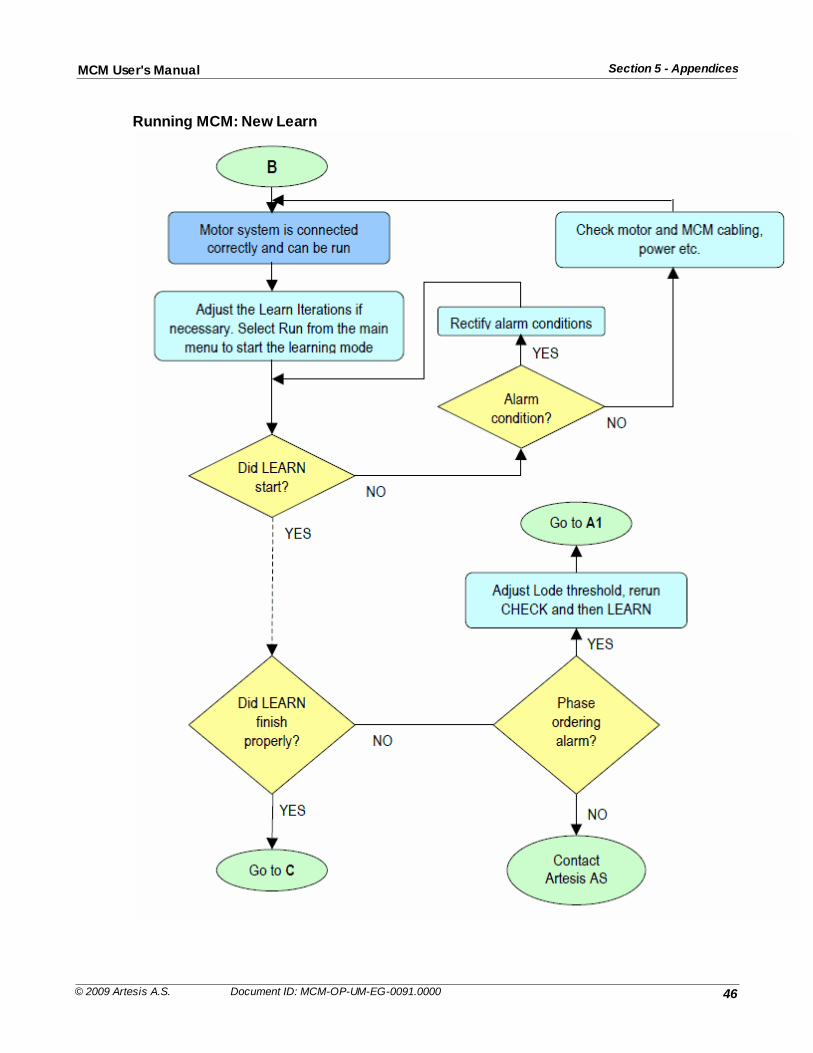
46
Section 5 - AppendicesMCM User's Manual
© 2009 Artesis A.S. Document ID: MCM-OP-UM-EG-0091.0000
Running MCM: New Learn
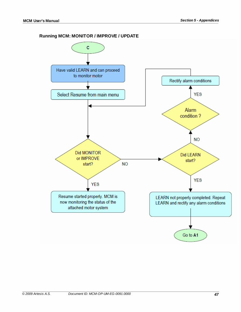
47
Section 5 - AppendicesMCM User's Manual
© 2009 Artesis A.S. Document ID: MCM-OP-UM-EG-0091.0000
Running MCM: MONITOR / IMPROVE / UPDATE
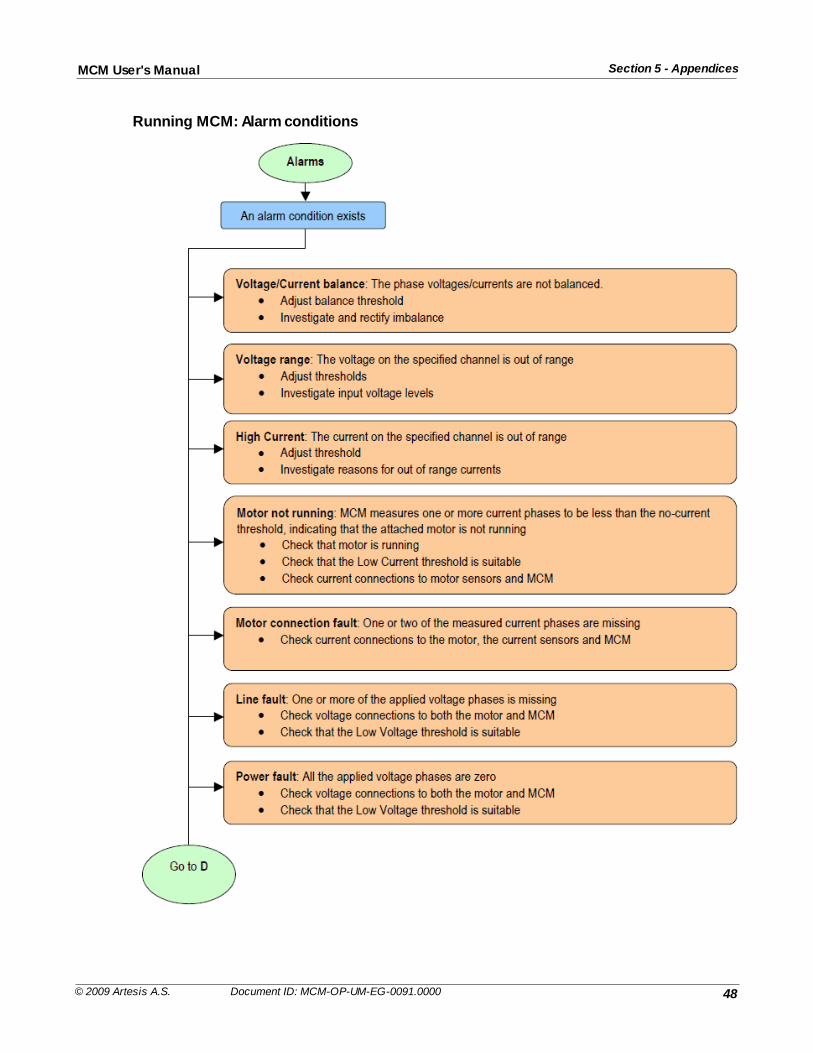
48
Section 5 - AppendicesMCM User's Manual
© 2009 Artesis A.S. Document ID: MCM-OP-UM-EG-0091.0000
Running MCM: Alarm conditions
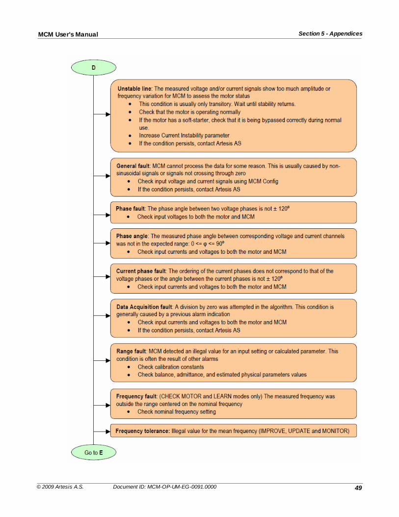
49
Section 5 - AppendicesMCM User's Manual
© 2009 Artesis A.S. Document ID: MCM-OP-UM-EG-0091.0000
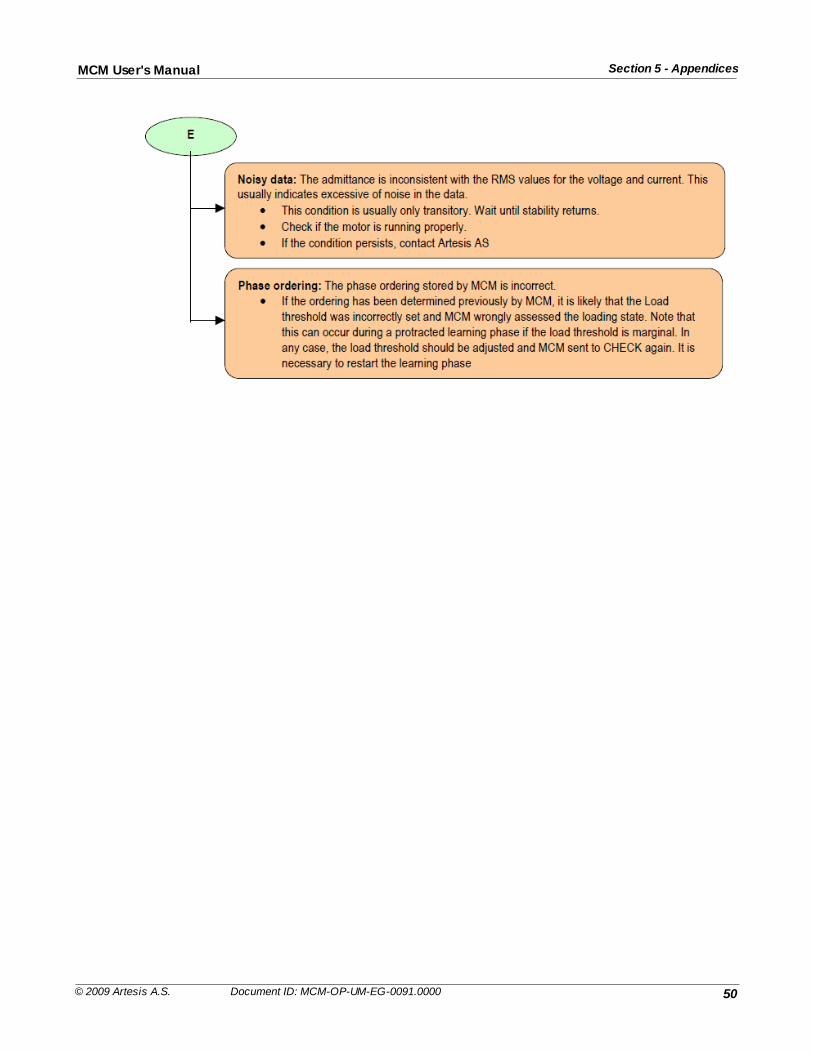
50
Section 5 - AppendicesMCM User's Manual
© 2009 Artesis A.S. Document ID: MCM-OP-UM-EG-0091.0000
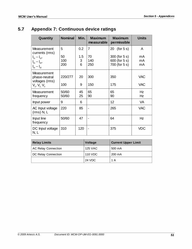
51
Section 5 - AppendicesMCM User's Manual
© 2009 Artesis A.S. Document ID: MCM-OP-UM-EG-0091.0000
5.7 Appendix 7: Continuous device ratings
Quantity Nominal Min. Maximummeasurable
Maximumpermissible
Units
Measurementcurrents (rms) I11 – I12,
I21 – I22,
I31 – I32
5
50100200
0.2
1.536
7
70140250
20 (for 5 s)
300 (for 5 s)600 (for 5 s)700 (for 5 s)
A
mAmAmA
Measurementphase-neutralvoltages (rms)V1, V2 , V3
220/277
100
20
9
300
150
350
175
VAC
VAC
Measurementfrequency
50/6050/60
4525
6590
6590
HzHz
Input power 9 6 12 VA
AC Input voltage(rms) N, L
220 85 - 265 VAC
Input linefrequency
50/60 47 - 64 Hz
DC Input voltageN, L
310 120 - 375 VDC
Relay Limits Voltage Current Upper Limit
AC Relay Connection 125 VAC 500 mA
DC Relay Connection 110 VDC 200 mA
24 VDC 1 A


