MCP combo panel MCP combo panel USER MANUAL (MEA2 520-5JAN09) Please read this manual before operating your (MEA2.520-5JAN09) Please read this manual before operating your units and keep it for future reference. Virtual Reality Insight Virtual Reality Insight VRinsight 1 All stated here is subject to change without advanced notice for improvement. Tel : +82-31-284-7090~91 Fax : +82-31-284-7092 E-mail : [email protected]Web site : www.vrinsight.com
Transcript
MCP combo panelMCP combo panelUSER MANUAL
(MEA2 520-5JAN09)
Please read this manual before operating your
(MEA2.520-5JAN09)
Please read this manual before operating your units and keep it for future reference.
Virtual Reality InsightVirtual Reality Insight
VRinsight
1
All stated here is subject to change without advanced notice for improvement.
Tel : +82-31-284-7090~91 Fax : +82-31-284-7092 E-mail : [email protected] Web site : www.vrinsight.com
BEFORE USE : Thanks for purchasing VRi’s MCP Combo panel.Before operating your units, please read through this manual and keep it for future reference.For any further question, visit VRi’s web-site (www.vrinsight.com) or contact as below;
NOTE : This manual could be redistributed unless you modify the contents. This manual has been written out on a Serial FP v2/Jet Liner’s MCP combopanel basis.
All software (& software versions) stated here (MEA2.520-5JAN09) is subject to change without advanced notice for improvementto change without advanced notice for improvement.
If you want to download the latest driver version for panel & application programs, visit www.vrinsight.com
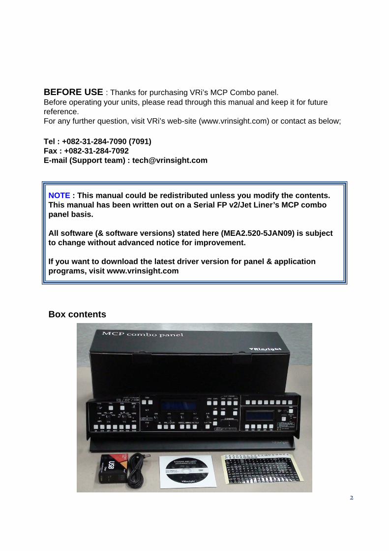
Box contents
2
VRinsight MCP combo panel
The MCP combo panel of VRinsight features various types of aircrafts’ panel with full control complement ; default aircrafts of MSFS, most freeware and commercial add-on aircraft (Wilco’s B737 Classic PMDG’s B737NG & 744 Level-D’s B767-add on aircraft (Wilco s B737 Classic, PMDG s B737NG & 744, Level D s B767300 and PSS’ A319,320,330,340). It is completely interfaced with MSFS9 and MSFSX through add-on software *SerialFP2” which enables MCP combo panel to perform full simulation with simple connection your computer through USB. Package including universal power supply adaptor (DC 5V).
The MCP combo panel is comprised of EFIS, MCP & COM (Instrument Radio) part to understand advanced flight controls for beginners and less advanced users p g gstarting flight simulation games at a first step.
Each control part; EFIS, MCP & COM has push buttons, rotary knobs, toggle S/Ws and/or 2 line character type LCDs offers actual flight circumstance with full control complement.
•SerialFP2 software supports all functions to MCP combo panel• MCP combo panel consumes high power. To avoid malfunction , do not use many other USB interfacing devices. We recommend using external power supply (DC 5V adaptor)
• If you want to use a USB hub, be sure that the USB hub must compliant with USB 2.0 standard. Otherwise it may cause a malfunction.
3
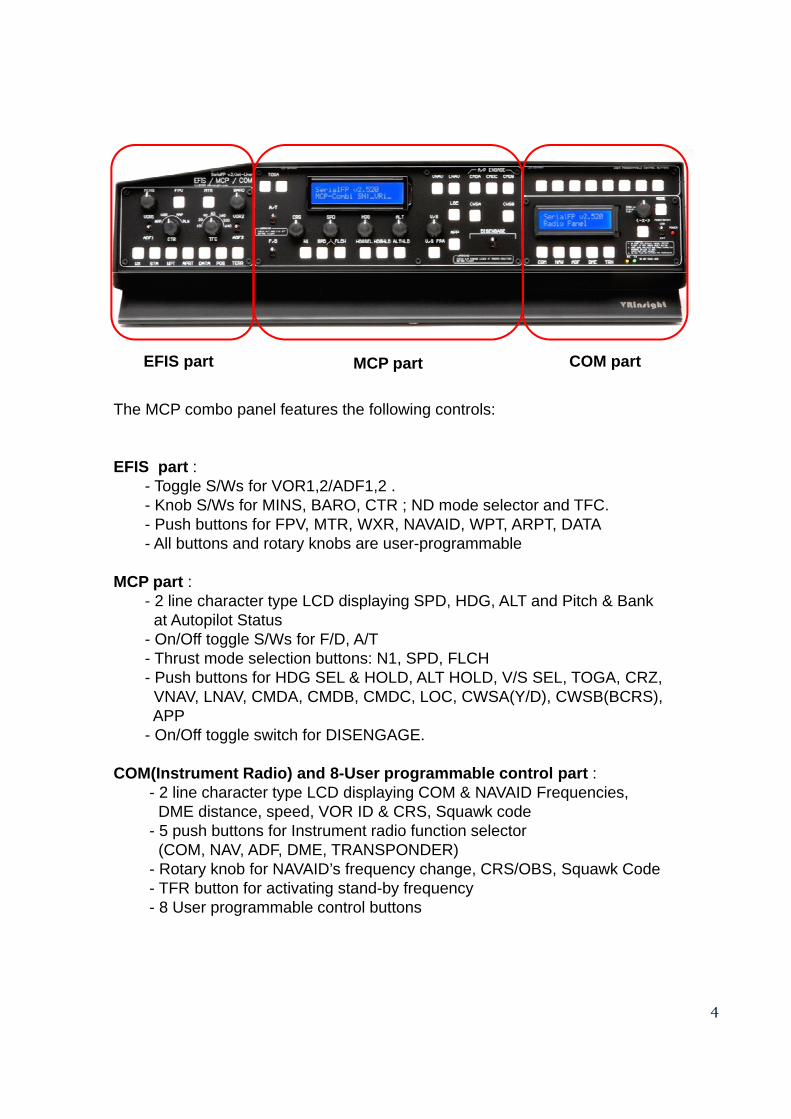
The MCP combo panel features the following controls:
EFIS part :- Toggle S/Ws for VOR1,2/ADF1,2 .
EFIS part MCP part COM part
Toggle S/Ws for VOR1,2/ADF1,2 .- Knob S/Ws for MINS, BARO, CTR ; ND mode selector and TFC.- Push buttons for FPV, MTR, WXR, NAVAID, WPT, ARPT, DATA - All buttons and rotary knobs are user-programmable
MCP part :- 2 line character type LCD displaying SPD, HDG, ALT and Pitch & Bank
at Autopilot Statusp- On/Off toggle S/Ws for F/D, A/T- Thrust mode selection buttons: N1, SPD, FLCH- Push buttons for HDG SEL & HOLD, ALT HOLD, V/S SEL, TOGA, CRZ,
COM(Instrument Radio) and 8-User programmable control part :- 2 line character type LCD displaying COM & NAVAID Frequencies,
DME distance, speed, VOR ID & CRS, Squawk code- 5 push buttons for Instrument radio function selector
(COM, NAV, ADF, DME, TRANSPONDER)- Rotary knob for NAVAID’s frequency change, CRS/OBS, Squawk Code- TFR button for activating stand-by frequency
4
- 8 User programmable control buttons
Features
• Integrated unit with full radio stack function : EFIS part, MCP part, COM part
• All necessary buttons, switches and LCD panel to input SPD, VOR, HDG and all other functions for getting close to real flight.
• Offer actual flight circumstance via MCP combo panel with full control complement
• Full metal cases
• One year warranty
Technical specifications
• USB interface type to computer
• External power requirement : DC 5V adaptor or USB power supply type to MCP combo panel. We recommend using DC 5V adaptor.
• 50cm(W) x 14cm(H)
• 4Kg
Compatibility software
• Flight simulator 2004 / FSX by Microsoft
Operating software
• SerialFP2
5
SerialFP2 Installation
With MCP b l “I t ll DVD” i i l d d Wh i t it i DVD d iWith MCP combo panel, an “Install DVD” is included. When you insert it in DVD driver of your computer, “VRinsight HTML” document will be shown. Then click “SerialFP2” (operating software) and install it at a proper folder.“SerialFP2” is the main operating software of VRinsight used for all VRinsight flight panels.
SerialFP2 software supports full functions of MCP combo panel and completely interfaced with MSFS9 and MSFSX enables full simulation with simple connection withinterfaced with MSFS9 and MSFSX enables full simulation with simple connection with your computer through USB. Be sure that when installing SerialFP2, “Install USB-Serial Driver” must be checked.
After installation, you can find “SeiralFP2” in “All programs” of “Start menu”.
USB ConnectionUSB Connection
The connection between MCP combo panel and your computer is made using a USB cable that plugs into an USB port on your computer. If you want to use a USB hub, be sure that the USB hub must compliant with USB 2.0 standard. Otherwise it may cause a malfunction.
When you connect MCP combo panel to your computer at first, your computer willWhen you connect MCP combo panel to your computer at first, your computer will detect it and will describe the process step by step.
Power Connection
Power supplying of MCP combo panel is done by universal power supply adaptor DC 5V (Included in package) and/or USB port of your computer. Make sure that before trying to operate MCP combo panel, you must confirm the USB connection first in order to prevent malfunction.
Before trying to operate, be sure that LCD displaying is shown.
Run “SerialFP2”
When you confirm all setup processes done; “SerialFP2” installation, “USB connection” d “P ti ” d t t MCP b l
6
and “Power connection”, you are ready to operate MCP combo panel.
Download & install “FSUIPC”
Refer to “Download & install FSUIPC” at “Download” part of www.vrinsight.com
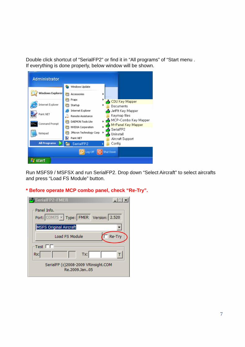
Double click shortcut of “SerialFP2” or find it in “All programs” of “Start menu .If everything is done properly, below window will be shown. e e yt g s do e p ope y, be o do be s o
Run MSFS9 / MSFSX and run SerialFP2. Drop down “Select Aircraft” to select aircrafts and press “Load FS Module” button.
* Before operate MCP combo panel, check “Re-Try”.
7
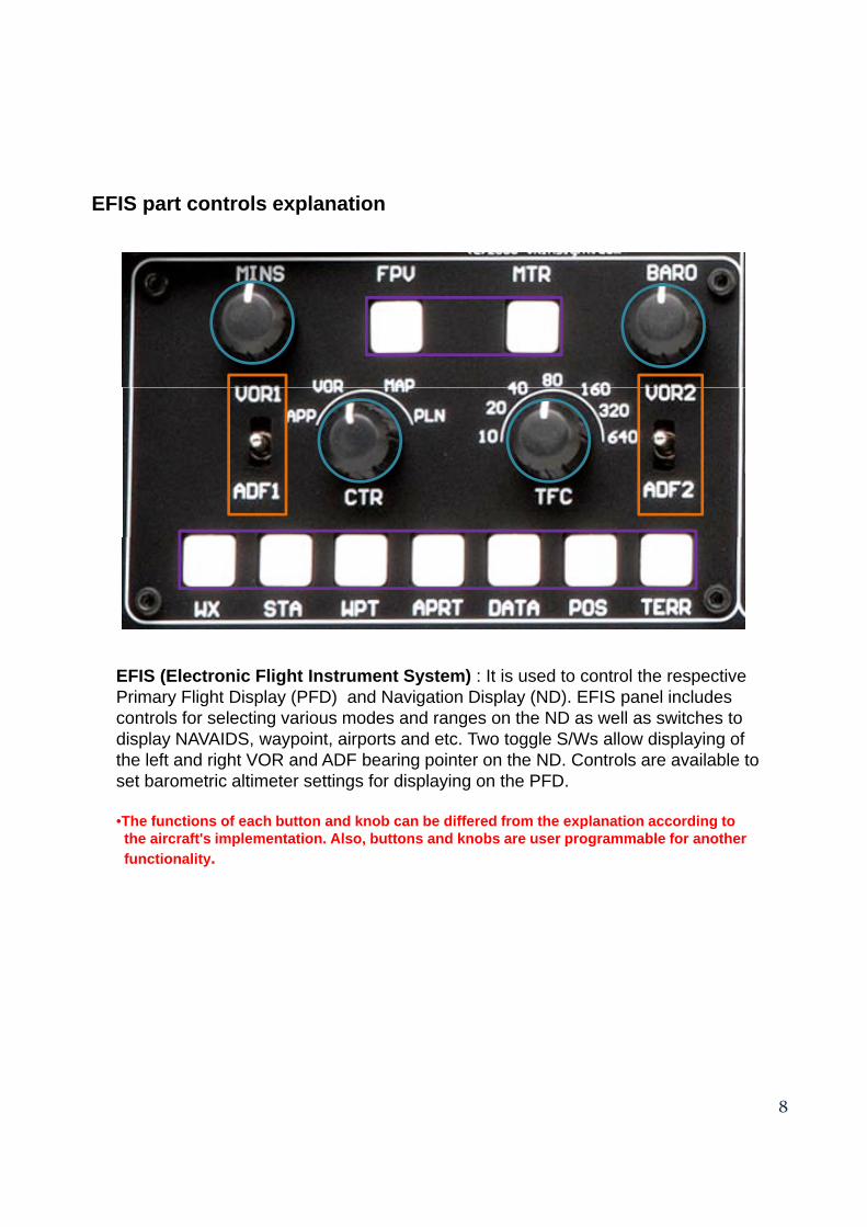
EFIS part controls explanation
EFIS (Electronic Flight Instrument System) : It is used to control the respective Primary Flight Display (PFD) and Navigation Display (ND). EFIS panel includes controls for selecting various modes and ranges on the ND as well as switches to display NAVAIDS, waypoint, airports and etc. Two toggle S/Ws allow displaying of the left and right VOR and ADF bearing pointer on the ND. Controls are available to set barometric altimeter settings for displaying on the PFD.
•The functions of each button and knob can be differed from the explanation according to the aircraft's implementation Also buttons and knobs are user programmable for anotherthe aircraft s implementation. Also, buttons and knobs are user programmable for another functionality.
8
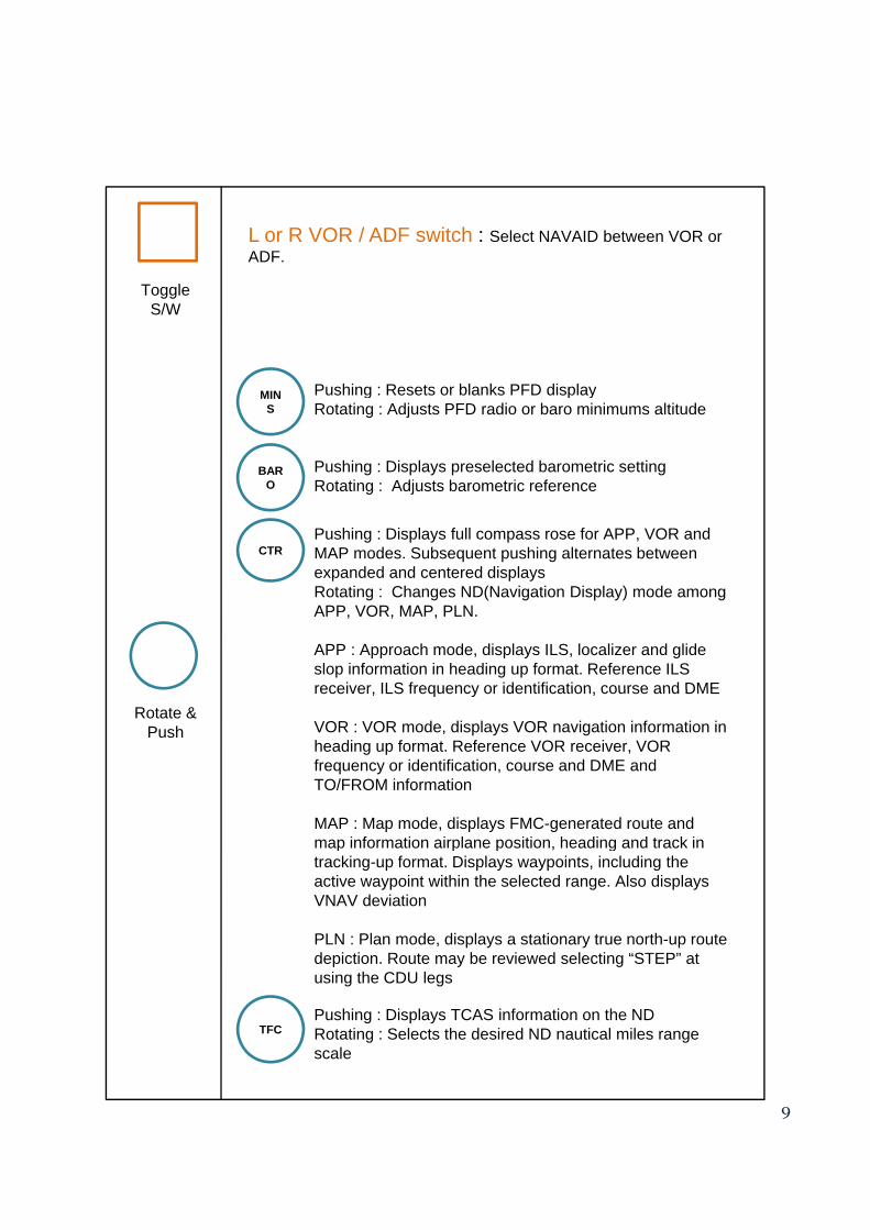
L or R VOR / ADF switch : Select NAVAID between VOR orL or R VOR / ADF switch : Select NAVAID between VOR or ADF.
Pushing : Resets or blanks PFD display
Toggle S/W
Pushing : Resets or blanks PFD displayRotating : Adjusts PFD radio or baro minimums altitude
Pushing : Displays full compass rose for APP, VOR and
MINS
BARO
Pushing : Displays full compass rose for APP, VOR and MAP modes. Subsequent pushing alternates between expanded and centered displaysRotating : Changes ND(Navigation Display) mode among APP, VOR, MAP, PLN.
APP : Approach mode, displays ILS, localizer and glide slop information in heading up format. Reference ILS receiver ILS frequency or identification course and DME
CTR
receiver, ILS frequency or identification, course and DME
VOR : VOR mode, displays VOR navigation information in heading up format. Reference VOR receiver, VOR frequency or identification, course and DME and TO/FROM information
MAP : Map mode, displays FMC-generated route and map information airplane position heading and track in
Rotate & Push
map information airplane position, heading and track in tracking-up format. Displays waypoints, including the active waypoint within the selected range. Also displays VNAV deviation
PLN : Plan mode, displays a stationary true north-up route depiction. Route may be reviewed selecting “STEP” at using the CDU legs
9
Pushing : Displays TCAS information on the NDRotating : Selects the desired ND nautical miles range scale
TFC
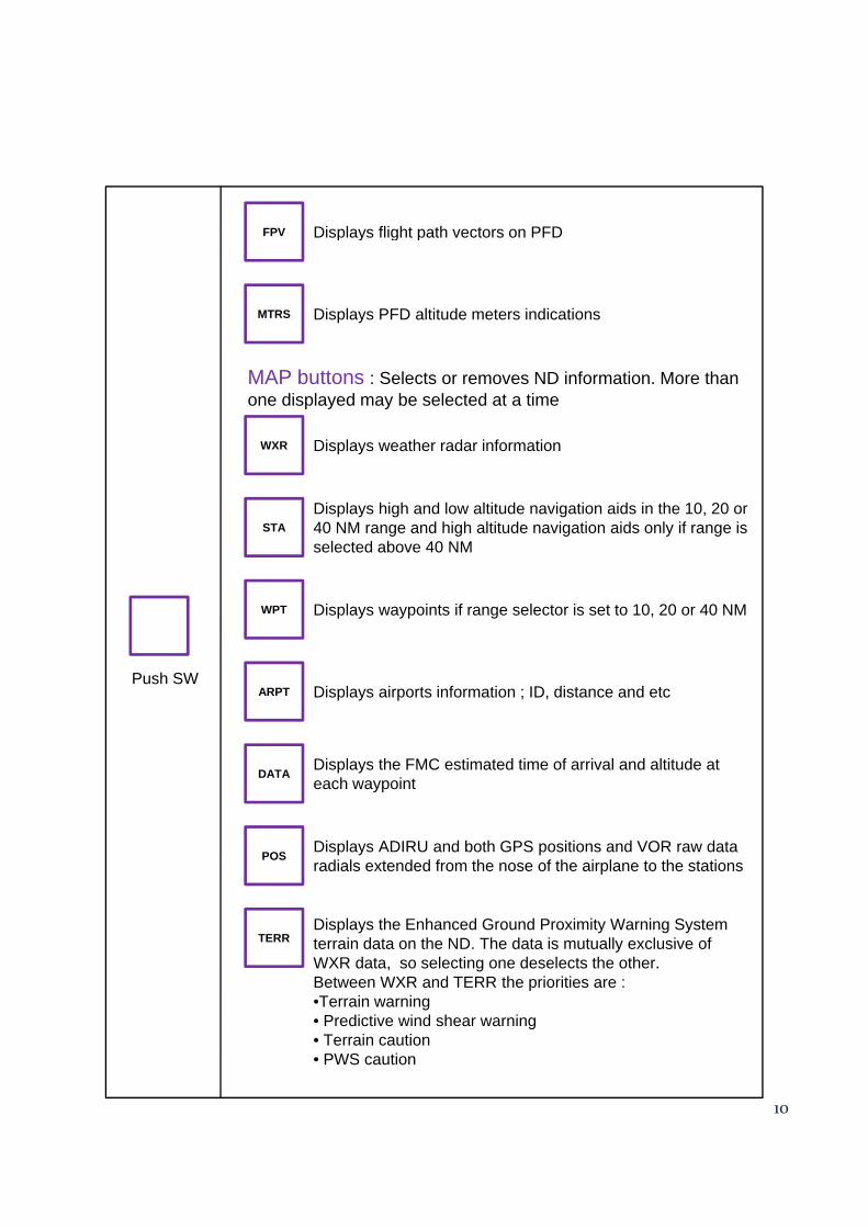
FPV Displays flight path vectors on PFDp y g p
MTRS Displays PFD altitude meters indications
MAP buttons : Selects or removes ND information. More than one displayed may be selected at a time
WXR Displays weather radar information
STADisplays high and low altitude navigation aids in the 10, 20 or 40 NM range and high altitude navigation aids only if range is selected above 40 NM
WPT Displays waypoints if range selector is set to 10, 20 or 40 NM
ARPT Di l i t i f ti ID di t d tPush SW
ARPT Displays airports information ; ID, distance and etc
DATA Displays the FMC estimated time of arrival and altitude at each waypoint
POS Displays ADIRU and both GPS positions and VOR raw data radials extended from the nose of the airplane to the stations.
TERRDisplays the Enhanced Ground Proximity Warning System terrain data on the ND. The data is mutually exclusive of WXR data, so selecting one deselects the other.Between WXR and TERR the priorities are :
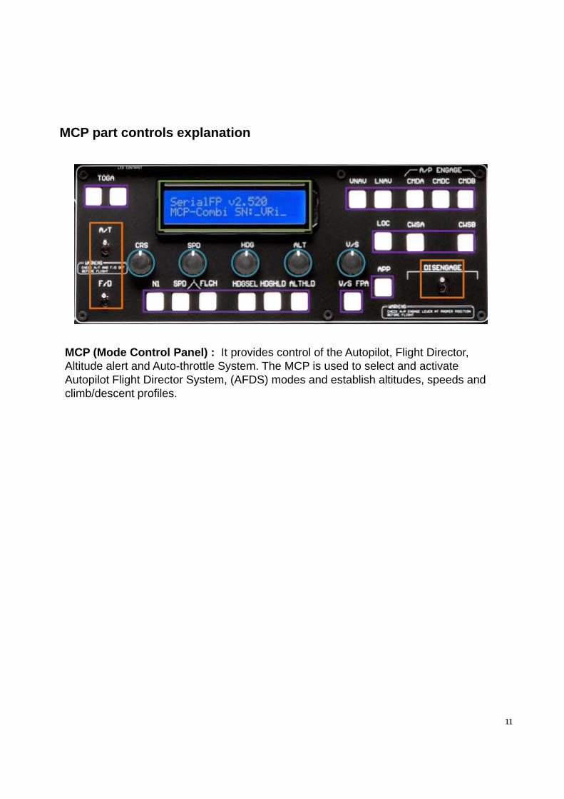
MCP (Mode Control Panel) : It provides control of the Autopilot Flight DirectorMCP (Mode Control Panel) : It provides control of the Autopilot, Flight Director, Altitude alert and Auto-throttle System. The MCP is used to select and activate Autopilot Flight Director System, (AFDS) modes and establish altitudes, speeds and climb/descent profiles.
11
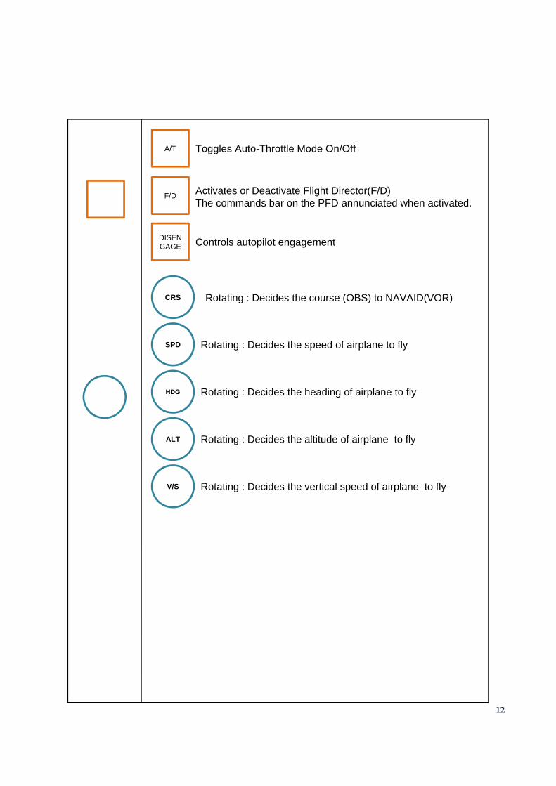
A/T Toggles Auto-Throttle Mode On/Offgg
F/D Activates or Deactivate Flight Director(F/D)The commands bar on the PFD annunciated when activated.
DISENGAGE Controls autopilot engagement
CRS
GAGE
SPD Rotating : Decides the speed of airplane to fly
Rotating : Decides the course (OBS) to NAVAID(VOR)
SPD Rotating : Decides the speed of airplane to fly
HDG Rotating : Decides the heading of airplane to fly
ALT Rotating : Decides the altitude of airplane to flyALT Rotating : Decides the altitude of airplane to fly
V/S Rotating : Decides the vertical speed of airplane to fly
12
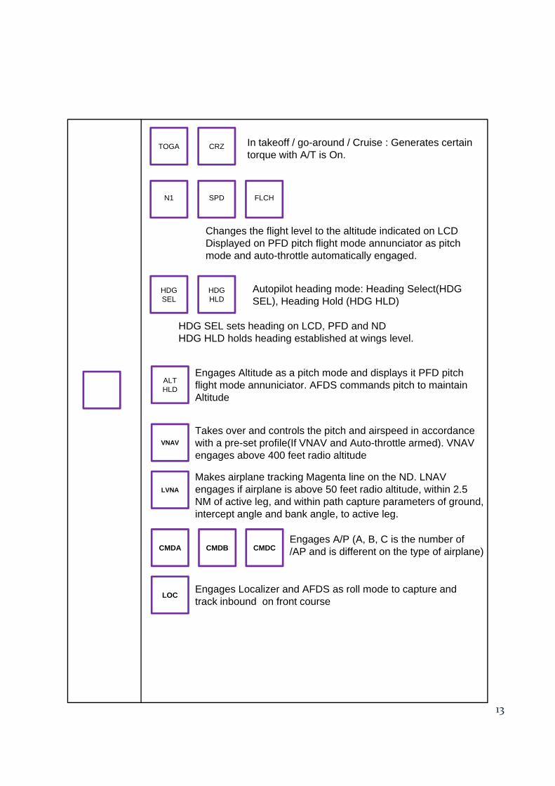
CRZTOGA In takeoff / go-around / Cruise : Generates certain t ith A/T i O
N1 SPD
Changes the flight level to the altitude indicated on LCDDisplayed on PFD pitch flight mode annunciator as pitch
FLCH
torque with A/T is On.
p y p g pmode and auto-throttle automatically engaged.
HDGSEL
HDGHLD
HDG SEL sets heading on LCD, PFD and NDHDG HLD holds heading established at wings level.
Autopilot heading mode: Heading Select(HDG SEL), Heading Hold (HDG HLD)
Takes over and controls the pitch and airspeed in accordance ith t fil (If VNAV d A t th ttl d) VNAVVNAV
ALTHLD
Engages Altitude as a pitch mode and displays it PFD pitch flight mode annuniciator. AFDS commands pitch to maintain Altitude
with a pre-set profile(If VNAV and Auto-throttle armed). VNAV engages above 400 feet radio altitude
E A/P (A B C i th b f
VNAV
LVNA
Makes airplane tracking Magenta line on the ND. LNAV engages if airplane is above 50 feet radio altitude, within 2.5 NM of active leg, and within path capture parameters of ground, intercept angle and bank angle, to active leg.
Engages A/P (A, B, C is the number of /AP and is different on the type of airplane)CMDA CMDB CMDC
LOC Engages Localizer and AFDS as roll mode to capture and track inbound on front course
13
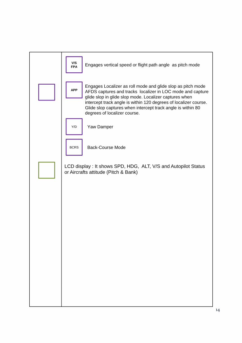
V/S FPA Engages vertical speed or flight path angle as pitch mode
APPEngages Localizer as roll mode and glide slop as pitch modeAFDS captures and tracks localizer in LOC mode and capture glide slop in glide slop mode. Localizer captures when intercept track angle is within 120 degrees of localizer course. Glide slop captures when intercept track angle is within 80
FPA g g p g p g p
Y/D
BCRS
Glide slop captures when intercept track angle is within 80 degrees of localizer course.
Yaw Damper
Back-Course Mode
LCD display : It shows SPD, HDG, ALT, V/S and Autopilot Status or Aircrafts attitude (Pitch & Bank)
14
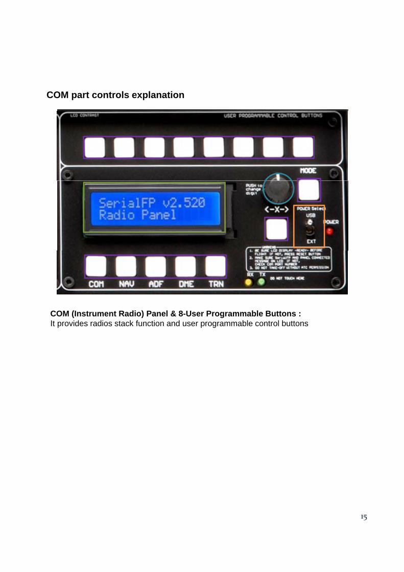
COM part controls explanation
COM (Instrument Radio) Panel & 8-User Programmable Buttons : It id di t k f ti d bl t l b ttIt provides radios stack function and user programmable control buttons.
15
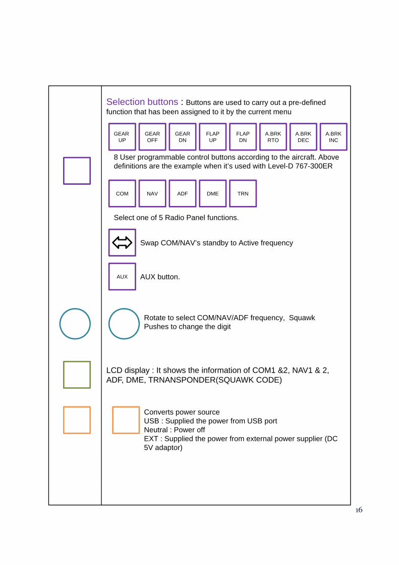
Selection buttons : Buttons are used to carry out a pre-defined f ti th t h b i d t it b th t
GEAR OFF
GEARUP
GEAR DN
FLAPUP
FLAPDN
A.BRK RTO
A.BRKDEC
A.BRKINC
function that has been assigned to it by the current menu
8 User programmable control buttons according to the aircraft. Above definitions are the example when it’s used with Level-D 767-300ER.
COM TRNNAV ADF DME
Swap COM/NAV’s standby to Active frequency
Select one of 5 Radio Panel functions.
AUX AUX button.
Rotate to select COM/NAV/ADF frequency SquawkRotate to select COM/NAV/ADF frequency, SquawkPushes to change the digit
LCD display : It shows the information of COM1 &2, NAV1 & 2, ADF, DME, TRNANSPONDER(SQUAWK CODE)
Converts power source USB : Supplied the power from USB portNeutral : Power offEXT : Supplied the power from external power supplier (DC 5V adaptor)
16
Preparing MCP combo panel before flight
Check installation “SerialFP2”.
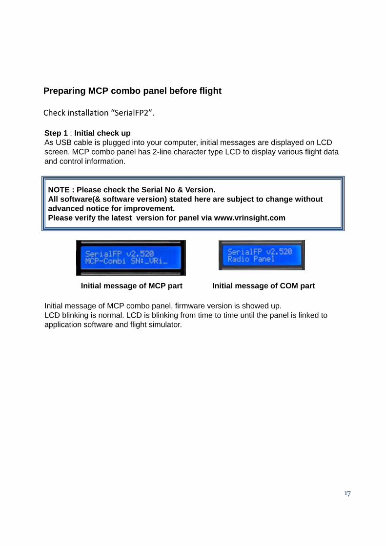
Step 1 : Initial check upAs USB cable is plugged into your computer, initial messages are displayed on LCD screen. MCP combo panel has 2-line character type LCD to display various flight data and control information.
NOTE : Please check the Serial No & Version. All software(& software version) stated here are subject to change without advanced notice for improvement. Please verify the latest version for panel via www.vrinsight.com
Initial message of MCP combo panel firmware version is showed up
Initial message of MCP part Initial message of COM part
Initial message of MCP combo panel, firmware version is showed up. LCD blinking is normal. LCD is blinking from time to time until the panel is linked to application software and flight simulator.
17
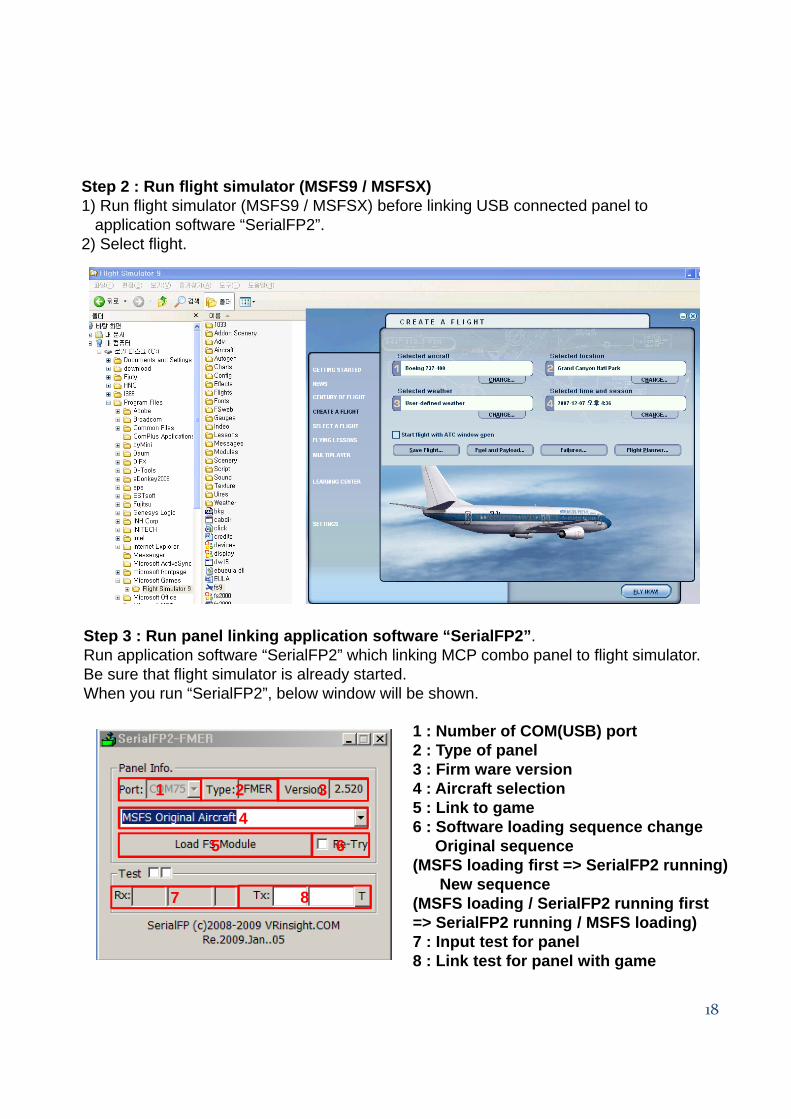
Step 2 : Run flight simulator (MSFS9 / MSFSX)1) Run flight simulator (MSFS9 / MSFSX) before linking USB connected panel to
Step 3 : Run panel linking application software “SerialFP2”.Run application software “SerialFP2” which linking MCP combo panel to flight simulator. Be sure that flight simulator is already started.When you run “SerialFP2”, below window will be shown.
1 : Number of COM(USB) port 2 : Type of panel3 Fi i3 : Firm ware version4 : Aircraft selection5 : Link to game6 : Software loading sequence change
Original sequence(MSFS loading first => SerialFP2 running)
New sequence(MSFS loading / SerialFP2 running first
1 2 3
45 6
7 8
18
(MSFS loading / SerialFP2 running first=> SerialFP2 running / MSFS loading)7 : Input test for panel8 : Link test for panel with game
7 8
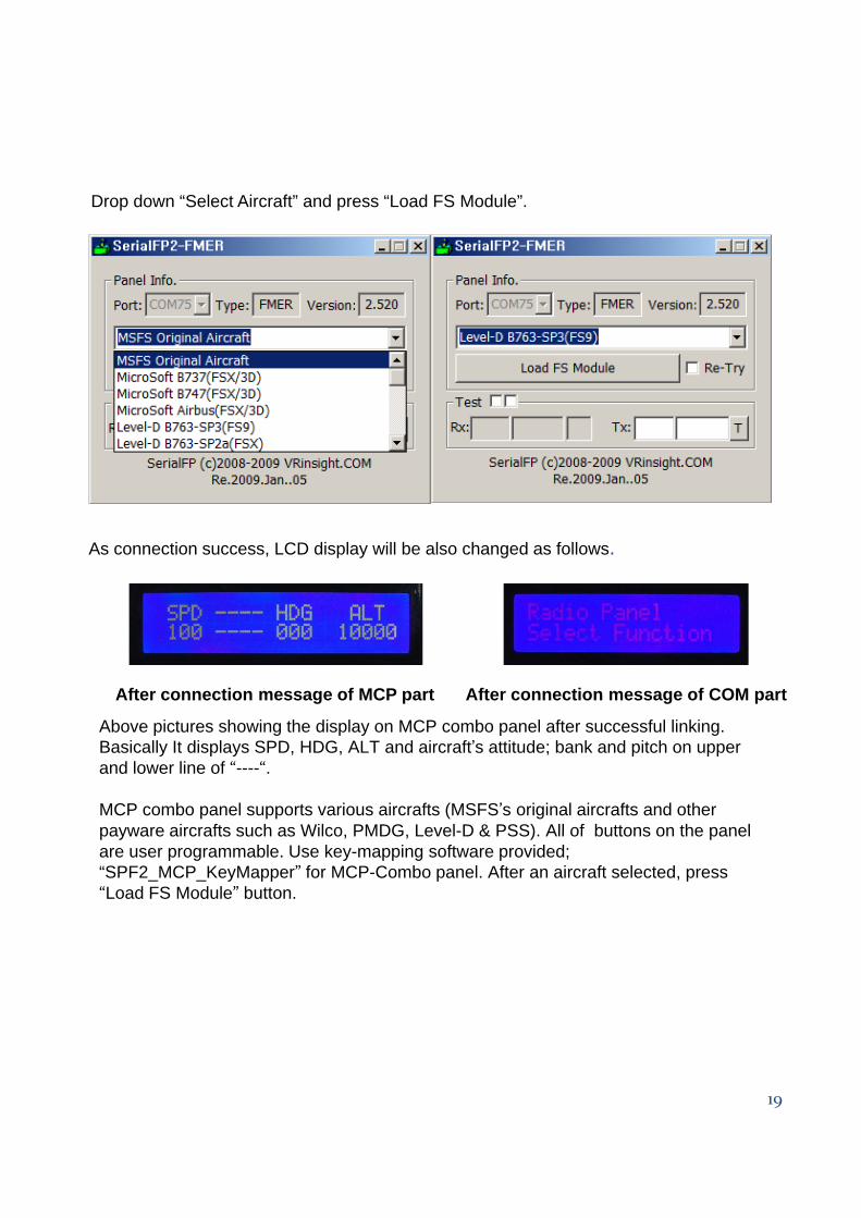
Drop down “Select Aircraft” and press “Load FS Module”.
As connection success, LCD display will be also changed as follows.
Above pictures showing the display on MCP combo panel after successful linking. Basically It displays SPD, HDG, ALT and aircraft’s attitude; bank and pitch on upper and lower line of “----“.
MCP combo panel supports various aircrafts (MSFS’s original aircrafts and other payware aircrafts such as Wilco PMDG Level-D & PSS) All of buttons on the panel
After connection message of MCP part After connection message of COM part
payware aircrafts such as Wilco, PMDG, Level-D & PSS). All of buttons on the panel are user programmable. Use key-mapping software provided; “SPF2_MCP_KeyMapper” for MCP-Combo panel. After an aircraft selected, press “Load FS Module” button.
19
Key-command sticker
key-command sticker is provided with product and enclosed DVD has “KeyCap_Decal.pdf” file for “LETTERING” based on MSFS9 / MSFSX . Please print it out and use for your purpose.
Payware aircrafts.
MCP combo panel supports various type of aircrafts including default aircraft of MSFS,freeware and payware Supported payware aircrafts are;freeware and payware. Supported payware aircrafts are;MSFS Original Aircraft Level-D B763-SP3(FS9) Level-D B763-SP2a(FSX)PMDG-B737/747(FS9) PMDG-B737 Only(FS9) PMDG-B737/747-FS2Crew(FS9)PMDG-B744(FSX) Wilco B737 PIC Wilco 777ER Wilco airbus ½ (2D) Wilco airbus ½ (3D) Wilco A380 v2Wilco embraer-ERJ Wilco embraer-Legacy Wilco Cessna Citation X PSS A319/320(FS9) PSS A330/340(FS9)PSS A319/320(FS9) PSS A330/340(FS9)Cooksky Super 80 proF1 ATR-72
All of controls on the panel, push buttons and rotary encoders, are programmable using key-mapping software. Any aircrafts can be supported, if key-commands are known at least and added on “SerialFP2” software’s aircraft list.
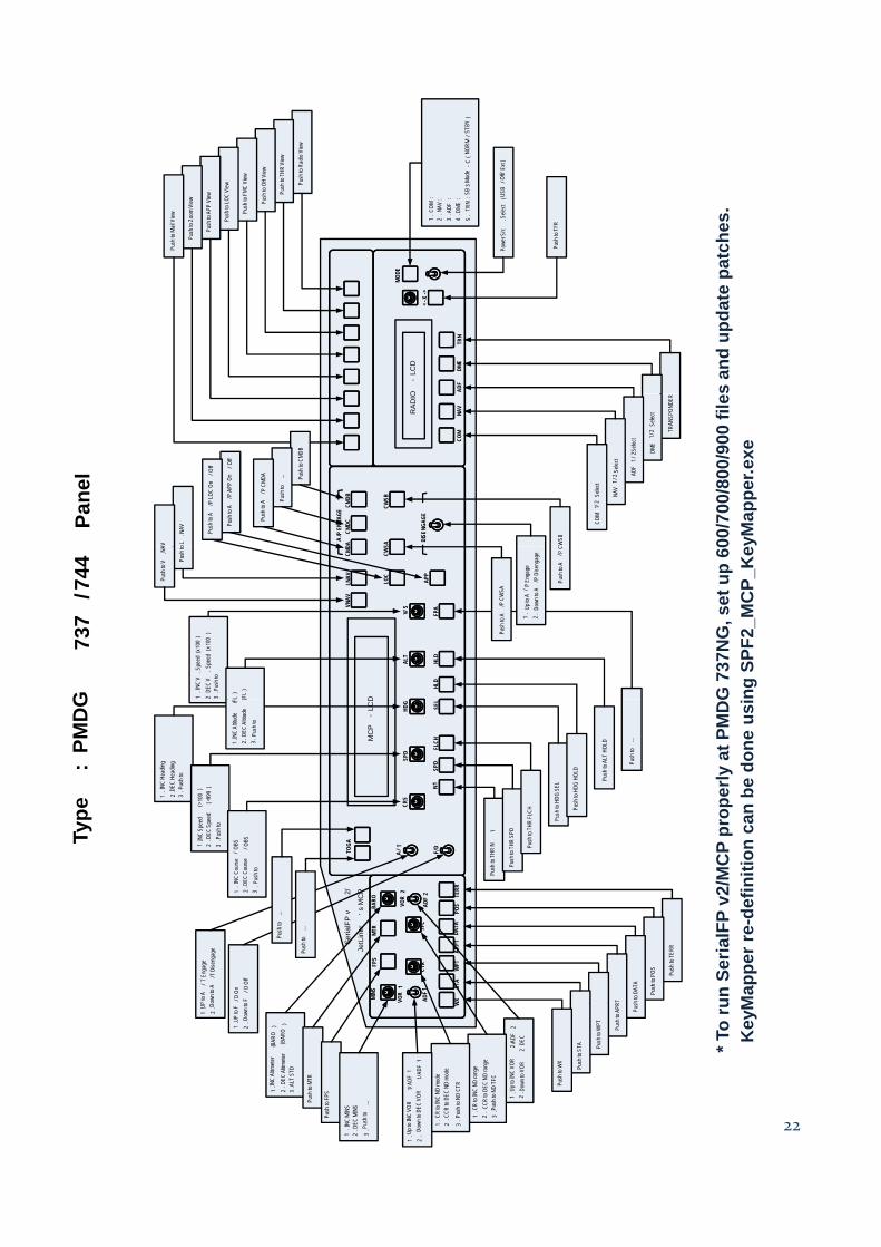
PMDG-737NG/744
PMDG controls aircrafts using key-commands. Many controls are missing in pre-defined key-commands. Fully defined command files are provided in enclosed DVD. Apply These files before flight with PMDG’s 737NG and 744 aircraft. To work correctly with provided definition file and the MCP combo panel, service pack and update patch must be applied; SP1 and update patch 1.3 for PMDG-737NG and update 1.x for PMDG-744.
Installing Key-Command Definition file
(1) PMDG’s key-command files are exist at …\Flight Simulator 9\PMDG.
20
( ) y gIt’s 737Kbd.ini for PMDG-737NG and 747400Kbd.ini for PMDG-744. Replace these files with provided.
(2) If only PMDG-737NG aircraft is installed,Find key-command definition file named “737Kbd.ini” at \Aircraft support\PMDG_B737NG_747400\Installed_737_only\ and copy to …\Flight Simulator 9\PMDG\.
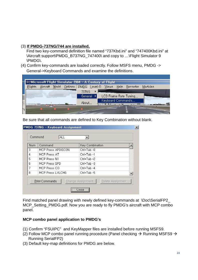
(3) If PMDG-737NG/744 are installed,Find two key-command definition file named “737Kbd.ini” and “747400Kbd.ini” at \ f \ G G \ \ S\Aircraft support\PMDG_B737NG_747400\ and copy to …\Flight Simulator 9\PMDG\.
(4) Confirm key-commands are loaded correctly. Follow MSFS menu, PMDG -> General->Keyboard Commands and examine the definitions.
Be sure that all commands are defined to Key Combination without blank.
Find matched panel drawing with newly defined key-commands at \Doc\SerialFP2_MCP_Setting_PMDG.pdf. Now you are ready to fly PMDG’s aircraft with MCP combo panel.
MCP combo panel application to PMDG’s
21
(1) Confirm “FSUIPC” and KeyMapper files are installed before running MSFS9.(2) Follow MCP combo panel running procedure (Panel checking Running MSFS9
Running SerialFP2)(3) Default key-map definitions for PMDG are below.
hes.
Push
to R
adio
View
Push
to T
HR V
iew
Push
to O
H Vi
ew
Push
to F
MC V
iew
Push
to LO
C Vi
ew
Push
to A
PP V
iew
Push
to Z
oom
View
h to M
ail V
iew 1. C
OM:
2. N
AV:
3. A
DF:
4. D
ME:
5.
TRN
: SB
3 Mo
de-C
(NO
RM/S
TBY
)
wer S
rc. S
elect
(USB
/Off /
Ext)
sh to
TFR
s an
d up
date
pat
ch
O-
LCD
ADF
DME
TRN
<-X
->
MODE
Pus
Pow Pus
00/7
00/8
00/9
00 fi
leyM
appe
r.exe
.
SADACM
DCCM
DB
CWSB
A/ P
ENG
AGE
DISE
NGAG
ER
AD
IO
COM
NAV
o L.N
AV
AV CWSB
TRAN
SPON
DER
DME
1/2
Selec
t
ADF
1/2 S
elect
NAV
1/2
Selec
t
COM
1/2
Selec
t
Push
to A
/P A
PP O
n/O
ff
Push
to A
/P LO
C On
/Off
Push
to C
MDB
Push
to
...
Push
to A
/ P C
MDA
Pane
l
G 7
37N
G, s
et u
p 60
ng S
PF2_
MC
P_K
e
ALT
V/S
HLD
HLD
FPA
D
VNAV
LNAV
LOC
APP
CWS
CMD
1. I
NC V
.Spe
ed(x
100
)2
. DEC
V.S
peed
(x10
0)
3. P
ush t
o
L)
(FL
)
Push
to
Push
to V
.NA
Push
to A
/ P C
Push
to A
/P C
WSA
1.
Up to
A/ P
Eng
age
2. D
own t
o A/ P
Dise
ngag
e
G
737
/744
P pr
oper
ly a
t PM
DG
on c
an b
e do
ne u
si
F/D/ TTOGA
CRS
N1SP
DFL
CH
SPD
HDG
SEL
MC
P-
LCD
1. IN
C He
ading
2. DE
C He
ading
3. P
ush t
o
1. IN
C Sp
eed
(>10
0)
2. D
EC S
peed
(<
999
)3
. Pus
h to
OBS
/ OBS
1. IN
C Al
titude
(FL2.
DEC
Altit
ude
(3.
Pus
h to
R N
1
o THR
SPD
Push
to T
HR F
LCH
Push
to H
DG S
EL
Push
to H
DG H
OLD
Push
to A
LT H
OLD
Push
to
...
Type
: PM
DG
un S
eria
lFP
v2/M
CP
Map
perr
e-de
finiti
o
Push
to T
ERR
Push
to P
OS
WX
STA
WPT
ARPT
DATA
POS
TERR
FPS
MTR
MINS
BARO
ADF1
VOR
1
CTR
TFC
ADF
2
VOR
2
FATSe
rialF
P v
2/
JetL
iner
’s M
CP
sh to
DAT
A
RT
1. I
NC C
ourse
/2
. DEC
Cou
rse3
. Pus
h to
/D O
no F
/D O
ff
P to
A/T
Eng
age
own t
o A/T
Dise
ngag
e
Push
to T
H
Push
to
Push
to
...
Push
to
...
22
* To
ruK
eyMW
1. U
p to I
NC V
OR2 /
ADF
22
. Dow
n to V
OR2
DEC
1. C
R to
INC
ND ra
nge
2. C
CR to
DEC
ND
rang
e3
. Pus
h to N
D TF
C
Pus
Push
to A
PR
Push
to W
PT
Push
to S
TA
Push
to W
X
1. U
P to
F2
. Dow
n to
1. UP
2. D
1. C
R to
INC
ND m
ode
2. C
CR to
DEC
ND
mode
3. P
ush t
o ND
CTR
1. U
p to I
NC V
OR1/
ADF
12
. Do
wn to
DEC
VOR
1/AD
F1
1. IN
C Al
timete
r(B
ARO
)2
. DEC
Altim
eter
( BAR
O)
3. A
LT S
TD
Push
to M
TR
Push
to F
PS
1. I
NC M
INS
2. D
EC M
INS
3. P
ush t
o ...
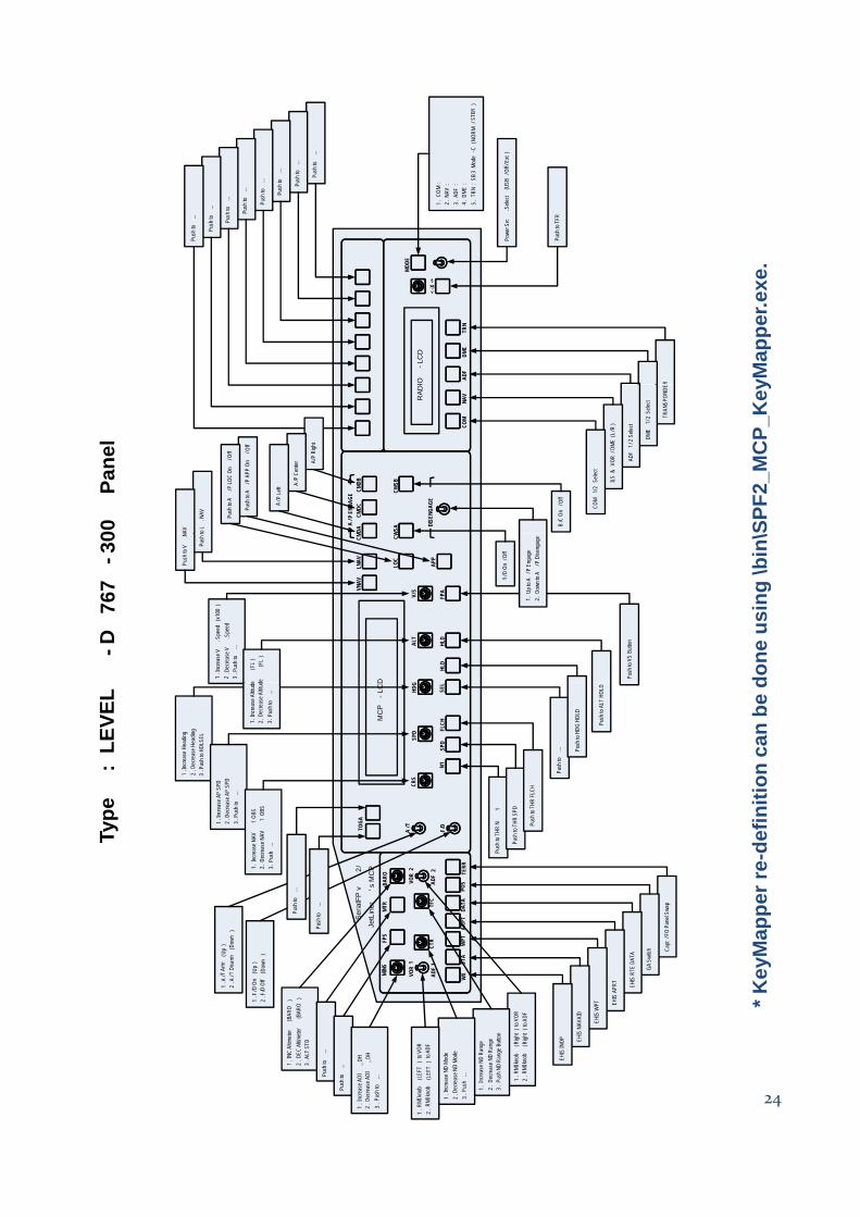
Level-D 767-300ER
S (S f ) f fLevel-D provides SDK (Software Development Kit) for 767-300ER aircrafts. External add-on software or hardware can access Level-D’s controls directly instead of key-command. This SDK is great for developers. Interfacing DLL module which is developed with Level-D’s SDK is provided for MCP combo panel. The DLL module is developed with SP3 of Level-D 767-300ER. Be sure this patch, SP3 is applied. Find matched panel drawing with interfacing module at \Doc\SerialFP2_MCP_Setting_LVLD_763.pdf. N d t fl L l D’ t t i ft ith MCP b lNow you are ready to fly Level-D’s greatest aircraft with MCP combo panel.
MCP combo panel application to Level-D’s
(1) All service packs (SP3) must be installed before running MSFS9 2004.(2) Follow MCP combo panel running procedure (Panel checking Running MSFS9
2004 Running SerialFP2).(3) Enjoy your flight Basic functions of panel are below(3) Enjoy your flight. Basic functions of panel are below.
23
Push
to
...
Push
to
...
Push
to
...
Push
to
...
Push
to
...
Push
to
...
Push
to
...
ush t
o ...
1. C
OM:
2. N
AV:
3. A
DF:
4. D
ME:
5. T
RN: S
B3 M
ode
-C (
NORM
/STB
Y)
ower
Src
. Sele
ct (U
SB/O
ff/Ex
t)
ush t
o TFR
yMap
per.e
xe.
IO-L
CD
ADF
DME
TRN
<-X
->
MODE
Pu Po Pu
R
SPF2
_MC
P_K
ey
WSA
MDA
CMDC
CMDB
CWSB
A/ P
ENG
AGE
DISE
NGAG
ER
ADI
COM
NAV
to L
.NAV
AV
B/C
On
/ Off
TRAN
SPON
DE
DME
1/2
Selec
t
ADF
1/2
Selec
t
ILS &
VOR
/DME
(L/R
)
COM
1/2
Selec
t
Push
to A
/P A
PP O
n/ O
ff
Push
to A
/P LO
C On
/Off
A/P
Righ
t
A/P
Cen
ter
A/P
Left
00
Pane
l
done
usi
ng \b
in\
ALT
V/S
HLD
HLD
FPA
D
VNAV
LNAV
LOC
APP
CWCM
1. In
creas
e V.S
peed
(x10
0)
2. D
ecre
ase V
.Spe
ed3
. Pus
h to
...
e(F
L)
e(F
L)
Push
to V
S Bu
tton
Push
t
Push
to V
.N
Y/D
On/O
ff
1. U
p to A
/ P E
ngag
e2.
Dow
n to A
/P D
iseng
age
-D
767
- 30
efin
ition
can
be
d
F/D
A/TTO
GA
CRS
N1SP
DFL
CH
SPD
HDG
SEL
MC
P-L
CD
1. In
creas
e Hea
ding
2. D
ecre
ase H
eadin
g3
. Pus
h to H
DLSE
L
1. In
creas
e AP
SPD
2. D
ecre
ase A
P SP
D3
. Pus
h to
...
1 OB
SV
1 OB
S1.
Incre
ase A
ltitud
e2.
Dec
reas
e Altit
ud3.
Pus
h to
...
HR N
1
to TH
R SP
D
Push
to T
HR F
LCH
Push
to
... Push
to H
DG H
OLD
Push
to A
LT H
OLD
ype
: LE
VEL
Key
Map
per r
e-de
Capt
/FO
Pane
l Swa
p
GA S
witch
WX
STA
WPT
ARPT
DATA
POS
TERR
FPS
MTR
MINS
BARO
ADF
1
VOR
1
CTR
TFC
ADF
2
VOR
2
FA
Seria
lFP
v2/
JetL
iner
’s M
CP
S RT
E DA
TA
1. In
creas
e NAV
2. D
ecre
ase N
A V3.
Pus
h ...
n (U
p)
f (D
own
)
A/T
Arm
(U
p)
A/T
Disa
rm(D
own
)
Push
to T
H
Push
t
Push
to
...
Push
to
...
Ty
24
* K
W
1. R
MI kn
ob(R
ight
) to V
OR2
. RMI
knob
(Righ
t) t
o ADF
1. In
creas
e ND
Rang
e2.
Dec
reas
e ND
Rang
e3.
Pus
h ND
Rang
e Bu
tton
EHI
EHIS
APR
T
EHIS
WPT
EHIS
NAV
AID
EHIS
INOP
1. F
/D O
n2
. F/D
Of f
1. A
2. A
1. In
creas
e ND
Mode
2. D
ecre
ase N
D Mo
de3
. Pus
h ...
1. R
MI kn
ob(L
EFT
) to
VOR
2. R
MI kn
ob(L
EFT
) to
ADF
1 . IN
C Al
timete
r(B
ARO
)2
. DEC
Altim
eter
(BAR
O)
3. A
LT S
TD
Push
to
...
Push
to
...
1. I
ncre
ase A
DI_ D
H2
. Dec
reas
e ADI
_DH
3. P
ush t
o ...
3-3. PSS-A330
PSS’s A330 aircraft is controlled by key-command similar to PMDG’s. Defect to PSS’s aircraft command definition is “fast rotation”,i.e. SPD, HDG, ALT etc, are missing. Response to incoming command from the panel is very slow. Newly defined key-command file is provided and find matched panel drawing at \Doc\ SerialFP2_MCP_Setting_PSS_A330.pdf.PSS A-330 aircraft’s configuration file where key-commands are defined exists at …\Flight Simulator 9\Pss\Airbus A3XX\. Copy provided new configuration file Aircraft
t\PSS A3XX\ fi 330 l t \Fli ht Si l t 9\P \Ai b A3XX\support\PSS_A3XX\ config330.pnl to …\Flight Simulator 9\Pss\Airbus A3XX\. Now you are ready to fly PSS A-330 aircraft with MCP combo panel.
25
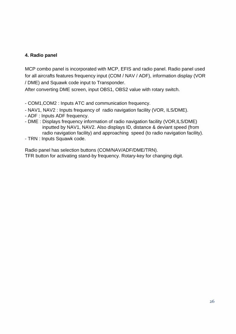
4. Radio panel
MCP combo panel is incorporated with MCP, EFIS and radio panel. Radio panel used for all aircrafts features frequency input (COM / NAV / ADF), information display (VOR / DME) and Squawk code input to Transponder. After converting DME screen, input OBS1, OBS2 value with rotary switch.
- COM1,COM2 : Inputs ATC and communication frequency.p q y- NAV1, NAV2 : Inputs frequency of radio navigation facility (VOR, ILS/DME).- ADF : Inputs ADF frequency.- DME : Displays frequency information of radio navigation facility (VOR,ILS/DME)
inputted by NAV1, NAV2. Also displays ID, distance & deviant speed (from radio navigation facility) and approaching speed (to radio navigation facility).
- TRN : Inputs Squawk code.
Radio panel has selection buttons (COM/NAV/ADF/DME/TRN). TFR button for activating stand-by frequency. Rotary-key for changing digit.
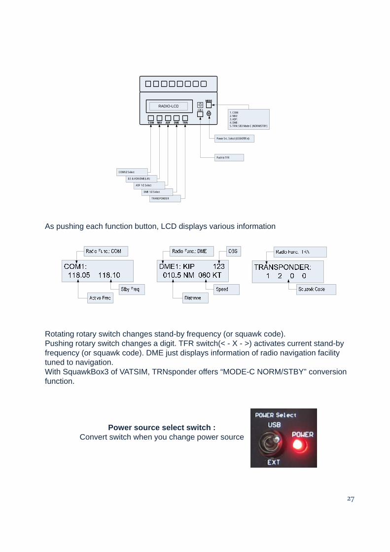
As pushing each function button, LCD displays various information
Rotating rotary switch changes stand-by frequency (or squawk code).Pushing rotary switch changes a digit. TFR switch(< - X - >) activates current stand-by frequency (or squawk code). DME just displays information of radio navigation facility tuned to navigation. With SquawkBox3 of VATSIM, TRNsponder offers “MODE-C NORM/STBY” conversion function.
Power source select switch :Convert switch when you change power source
27
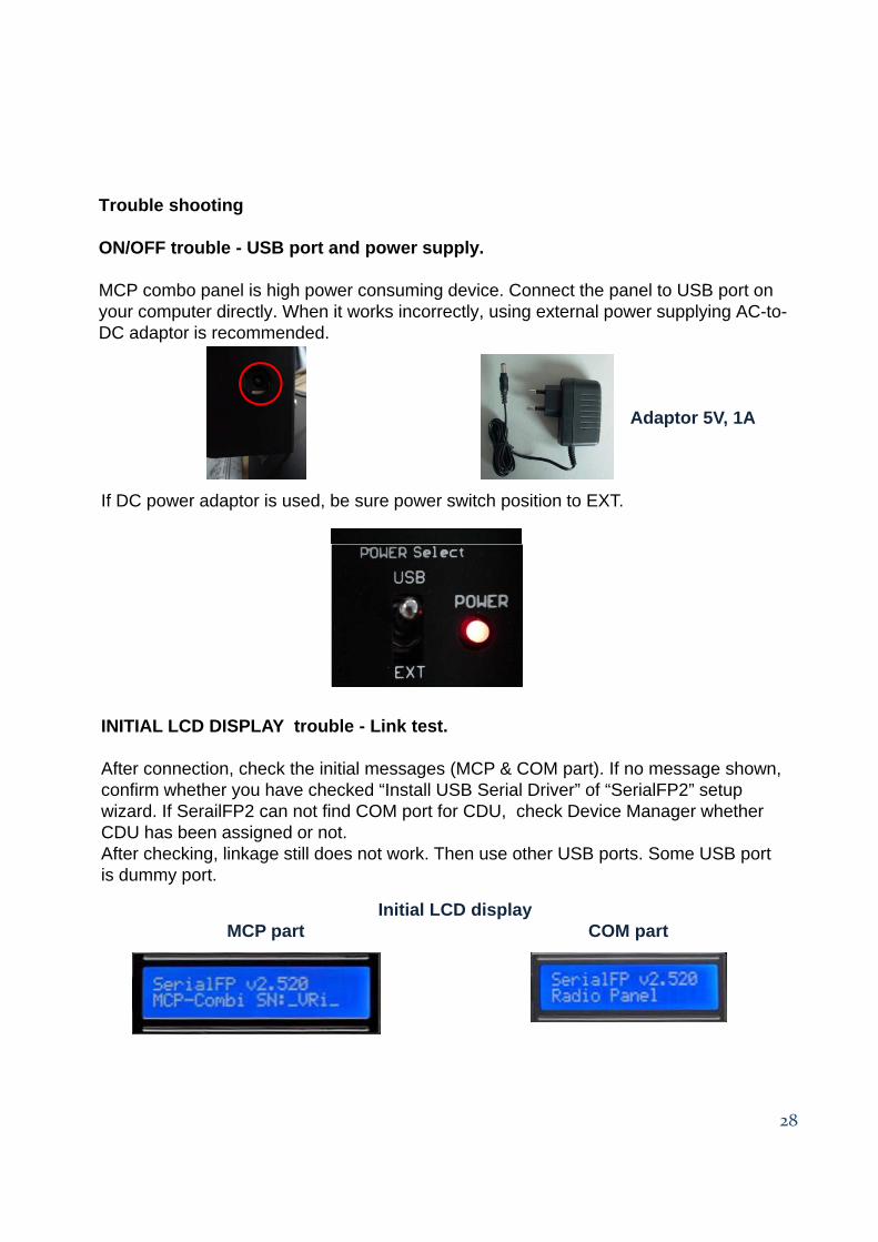
Trouble shooting
O /O SON/OFF trouble - USB port and power supply.
MCP combo panel is high power consuming device. Connect the panel to USB port on your computer directly. When it works incorrectly, using external power supplying AC-to-DC adaptor is recommended.
If DC power adaptor is used, be sure power switch position to EXT.
Adaptor 5V, 1A
INITIAL LCD DISPLAY trouble - Link test.
After connection, check the initial messages (MCP & COM part). If no message shown, confirm whether you have checked “Install USB Serial Driver” of “SerialFP2” setup wizard. If SerailFP2 can not find COM port for CDU, check Device Manager whether CDU has been assigned or not.Aft h ki li k till d t k Th th USB t S USB tAfter checking, linkage still does not work. Then use other USB ports. Some USB port is dummy port.
Initial LCD displayMCP part COM part
28
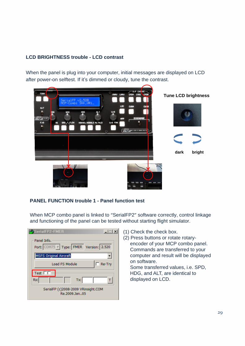
LCD BRIGHTNESS trouble - LCD contrast
When the panel is plug into your computer, initial messages are displayed on LCD after power-on selftest. If it’s dimmed or cloudy, tune the contrast.
Tune LCD brightness
dark brightdark bright
PANEL FUNCTION trouble 1 - Panel function test
When MCP combo panel is linked to “SerialFP2” software correctly, control linkage and functioning of the panel can be tested without starting flight simulator.
(1) Check the check box.(2) P b tt t t t(2) Press buttons or rotate rotary-
encoder of your MCP combo panel.Commands are transferred to your computer and result will be displayed on software. Some transferred values, i.e. SPD, HDG, and ALT, are identical to displayed on LCD
29
displayed on LCD.
PANEL FUNCTION trouble 2- FSUIPC check
Download & install FSUIPC is required for MCP combo panel use with Microsoft’s Flight Simulator. If you didn’t download & install, do it now. Basic function of FSUIPC is enough to operate. No registration is required.
Also check “FSUIPC.dll” file is in “\Program Files\Microsoft Games\Flight Simulator9\Modules”. Further information, see “download & install FSUIPC” part.
PANEL FUNCTION trouble 3 – Procedure check
1) Run MSFS first2) Download & install FSUIPC3) Setup “SerialFP2”4) Connect MCP panel to PC4) Connect MCP panel to PC5) Run “SerialFP2”6) Check “Re-Try” is checked7) Select your aircraft