Replacement Parts List No. 055223600 Revision J 06/2018 McQuay Central Station Air Handler Low & Medium Pressure LHD, LML, LSL, LYF, MMM, MSL 114 - 134 Vintage D LML, LSB, MMM, MSB 114 - 128 Vintage E Last Manufactured: 1999 To find your Daikin Applied parts distributor, call 1-800-377-2787 or visit www.DaikinApplied.com
Transcript
Replacement Parts List No. 055223600 Revision J 06/2018
McQuay
Central Station Air HandlerLow & Medium Pressure
LHD, LML, LSL, LYF, MMM, MSL114 - 134 Vintage D
LML, LSB, MMM, MSB114 - 128Vintage E
Last Manufactured: 1999
To find your Daikin Applied parts distributor, call 1-800-377-2787 or visit www.DaikinApplied.com
Air Handler; 114 - 134 Vintage D / 114 - 128 Vintage E Rev. J 06/18 RPL 552236 / Page 2
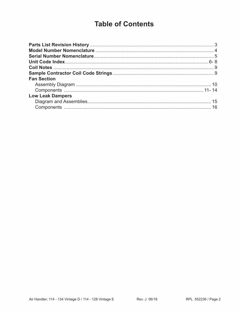
Table of Contents
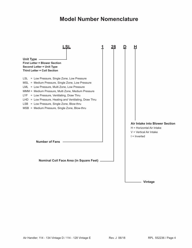
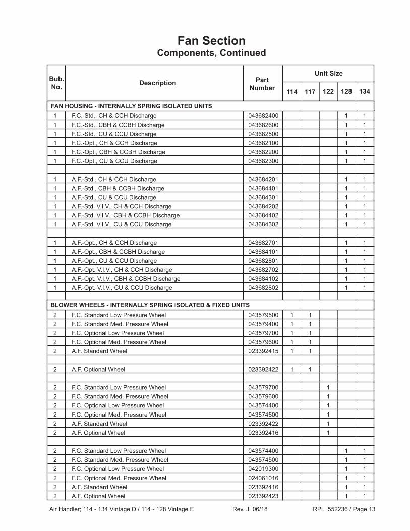
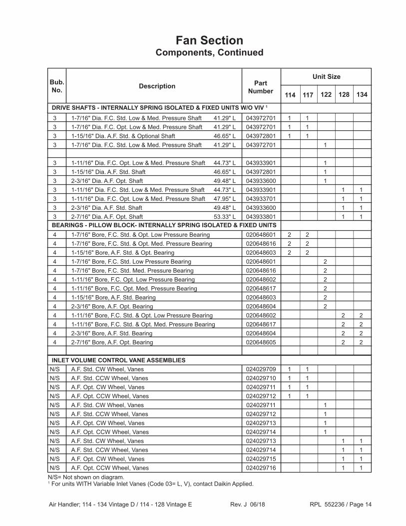
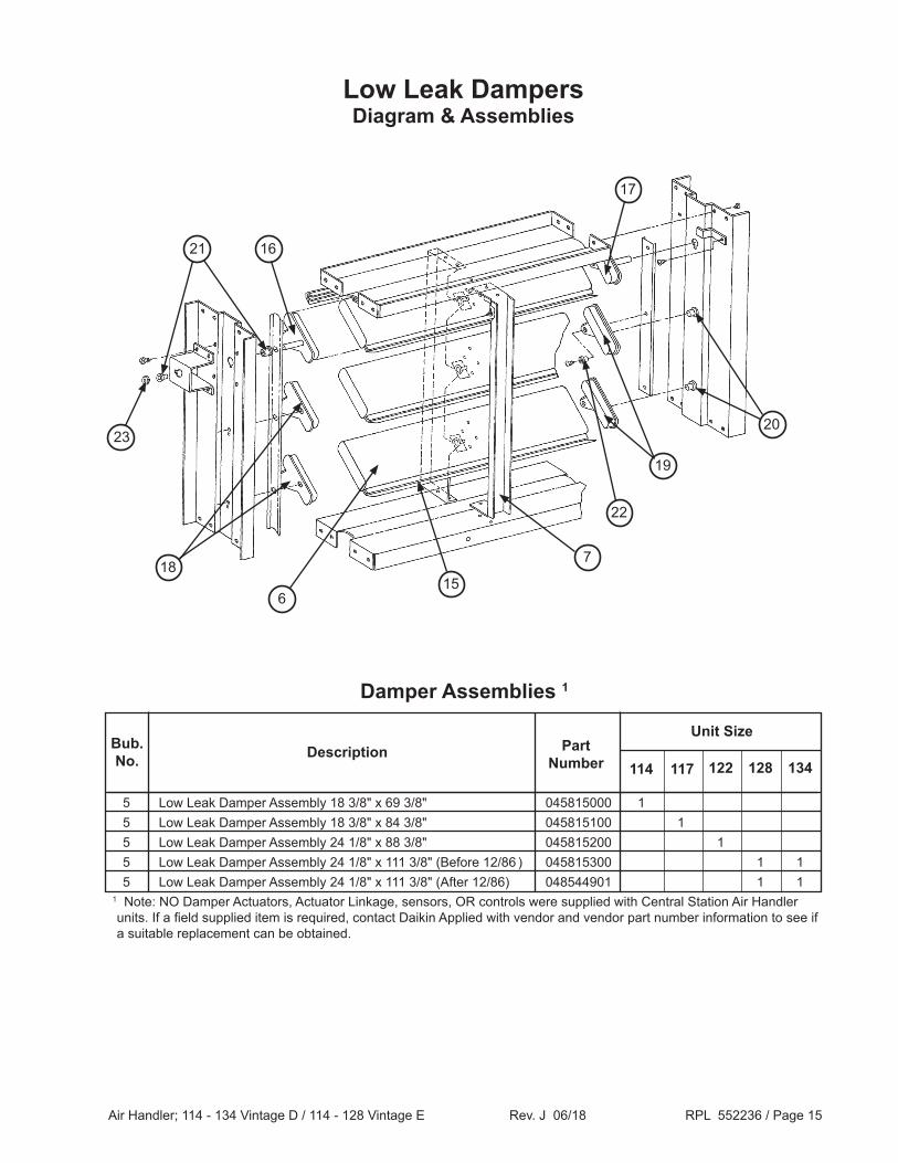
Parts List Revision History .............................................................................................. 3Model Number Nomenclature .......................................................................................... 4Serial Number Nomenclature ........................................................................................... 5Unit Code Index .............................................................................................................6- 8Coil Notes .......................................................................................................................... 9Sample Contractor Coil Code Strings ............................................................................. 9Fan Section Assembly Diagram ....................................................................................................... 10 Components .......................................................................................................... 11- 14Low Leak Dampers Diagram and Assemblies .............................................................................................. 15 Components ................................................................................................................ 16
Air Handler; 114 - 134 Vintage D / 114 - 128 Vintage E Rev. J 06/18 RPL 552236 / Page 3
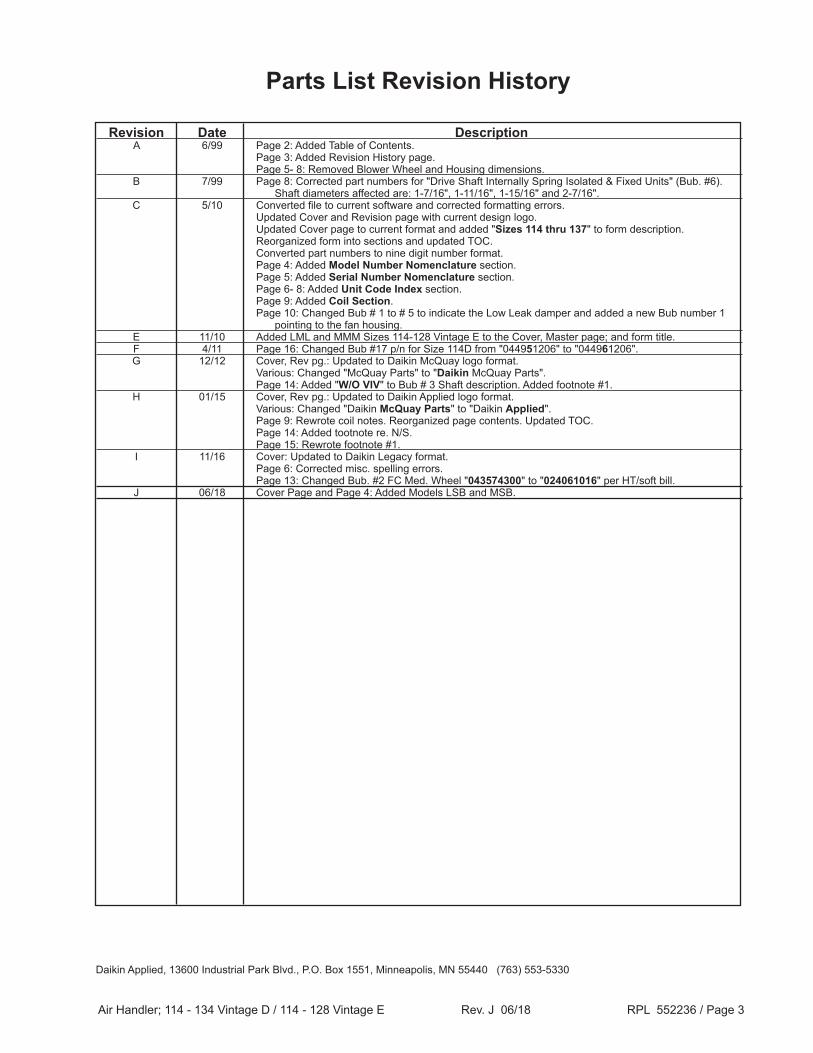
Revision Date Description A 6/99 Page 2: Added Table of Contents. Page 3: Added Revision History page. Page 5- 8: Removed Blower Wheel and Housing dimensions. B 7/99 Page 8: Corrected part numbers for "Drive Shaft Internally Spring Isolated & Fixed Units" (Bub. #6). Shaft diameters affected are: 1-7/16", 1-11/16", 1-15/16" and 2-7/16". C 5/10 Converted file to current software and corrected formatting errors. Updated Cover and Revision page with current design logo. Updated Cover page to current format and added "Sizes 114 thru 137" to form description. Reorganized form into sections and updated TOC. Converted part numbers to nine digit number format. Page 4: Added Model Number Nomenclature section. Page 5: Added Serial Number Nomenclature section. Page 6- 8: Added Unit Code Index section. Page 9: Added Coil Section. Page 10: Changed Bub # 1 to # 5 to indicate the Low Leak damper and added a new Bub number 1 pointing to the fan housing. E 11/10 Added LML and MMM Sizes 114-128 Vintage E to the Cover, Master page; and form title. F 4/11 Page 16: Changed Bub #17 p/n for Size 114D from "044951206" to "044961206". G 12/12 Cover, Rev pg.: Updated to Daikin McQuay logo format. Various: Changed "McQuay Parts" to "Daikin McQuay Parts". Page 14: Added "W/O VIV" to Bub # 3 Shaft description. Added footnote #1. H 01/15 Cover, Rev pg.: Updated to Daikin Applied logo format. Various: Changed "Daikin McQuay Parts" to "Daikin Applied". Page 9: Rewrote coil notes. Reorganized page contents. Updated TOC. Page 14: Added tootnote re. N/S. Page 15: Rewrote footnote #1. I 11/16 Cover: Updated to Daikin Legacy format. Page 6: Corrected misc. spelling errors. Page 13: Changed Bub. #2 FC Med. Wheel "043574300" to "024061016" per HT/soft bill. J 06/18 Cover Page and Page 4: Added Models LSB and MSB.
Air Handler; 114 - 134 Vintage D / 114 - 128 Vintage E Rev. J 06/18 RPL 552236 / Page 6
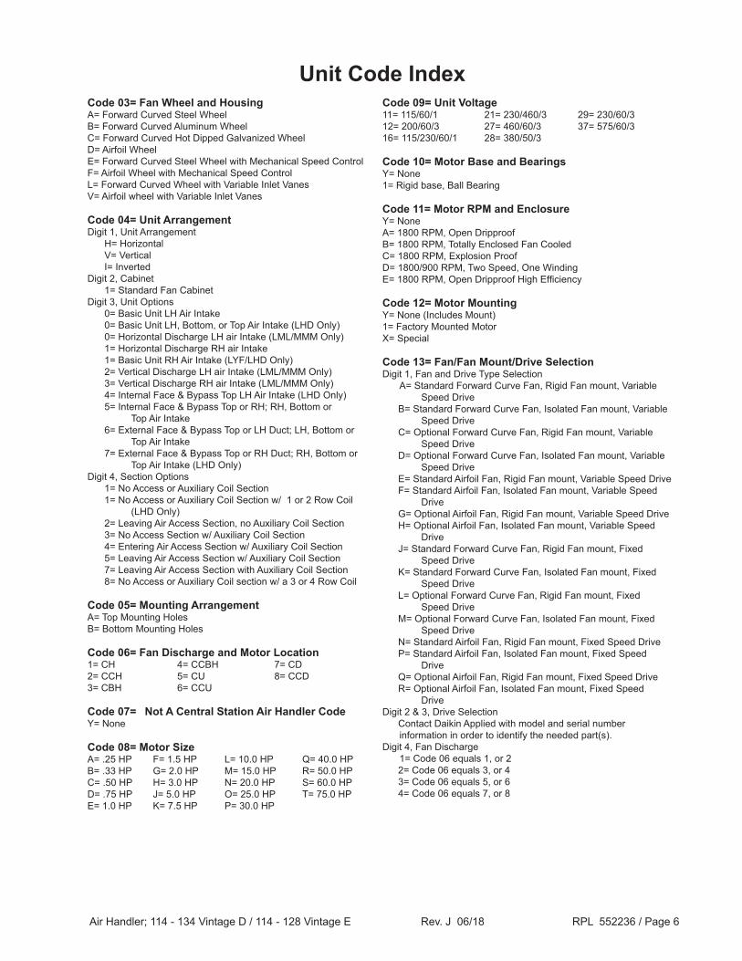
Unit Code IndexCode 03= Fan Wheel and HousingA= Forward Curved Steel WheelB= Forward Curved Aluminum WheelC= Forward Curved Hot Dipped Galvanized WheelD= Airfoil WheelE= Forward Curved Steel Wheel with Mechanical Speed ControlF= Airfoil Wheel with Mechanical Speed ControlL= Forward Curved Wheel with Variable Inlet VanesV= Airfoil wheel with Variable Inlet Vanes
Code 04= Unit ArrangementDigit 1, Unit Arrangement H= Horizontal V= Vertical I= InvertedDigit 2, Cabinet 1= Standard Fan CabinetDigit 3, Unit Options 0= Basic Unit LH Air Intake 0= Basic Unit LH, Bottom, or Top Air Intake (LHD Only) 0= Horizontal Discharge LH air Intake (LML/MMM Only) 1= Horizontal Discharge RH air Intake 1= Basic Unit RH Air Intake (LYF/LHD Only) 2= Vertical Discharge LH air Intake (LML/MMM Only) 3= Vertical Discharge RH air Intake (LML/MMM Only) 4= Internal Face & Bypass Top LH Air Intake (LHD Only) 5= Internal Face & Bypass Top or RH; RH, Bottom or Top Air Intake 6= External Face & Bypass Top or LH Duct; LH, Bottom or Top Air Intake 7= External Face & Bypass Top or RH Duct; RH, Bottom or Top Air Intake (LHD Only)Digit 4, Section Options 1= No Access or Auxiliary Coil Section 1= No Access or Auxiliary Coil Section w/ 1 or 2 Row Coil (LHD Only) 2= Leaving Air Access Section, no Auxiliary Coil Section 3= No Access Section w/ Auxiliary Coil Section 4= Entering Air Access Section w/ Auxiliary Coil Section 5= Leaving Air Access Section w/ Auxiliary Coil Section 7= Leaving Air Access Section with Auxiliary Coil Section 8= No Access or Auxiliary Coil section w/ a 3 or 4 Row Coil
Code 05= Mounting ArrangementA= Top Mounting HolesB= Bottom Mounting Holes
Code 06= Fan Discharge and Motor Location1= CH 4= CCBH 7= CD2= CCH 5= CU 8= CCD3= CBH 6= CCU
Code 07= Not A Central Station Air Handler CodeY= None
Code 08= Motor SizeA= .25 HP F= 1.5 HP L= 10.0 HP Q= 40.0 HPB= .33 HP G= 2.0 HP M= 15.0 HP R= 50.0 HPC= .50 HP H= 3.0 HP N= 20.0 HP S= 60.0 HPD= .75 HP J= 5.0 HP O= 25.0 HP T= 75.0 HPE= 1.0 HP K= 7.5 HP P= 30.0 HP
Code 10= Motor Base and BearingsY= None1= Rigid base, Ball Bearing
Code 11= Motor RPM and EnclosureY= NoneA= 1800 RPM, Open DripproofB= 1800 RPM, Totally Enclosed Fan CooledC= 1800 RPM, Explosion ProofD= 1800/900 RPM, Two Speed, One WindingE= 1800 RPM, Open Dripproof High Efficiency
Code 12= Motor Mounting Y= None (Includes Mount) 1= Factory Mounted MotorX= Special
Code 13= Fan/Fan Mount/Drive SelectionDigit 1, Fan and Drive Type Selection A= Standard Forward Curve Fan, Rigid Fan mount, Variable
Speed Drive B= Standard Forward Curve Fan, Isolated Fan mount, Variable
Speed Drive N= Standard Airfoil Fan, Rigid Fan mount, Fixed Speed Drive P= Standard Airfoil Fan, Isolated Fan mount, Fixed Speed
Drive Q= Optional Airfoil Fan, Rigid Fan mount, Fixed Speed Drive R= Optional Airfoil Fan, Isolated Fan mount, Fixed Speed
DriveDigit 2 & 3, Drive Selection Contact Daikin Applied with model and serial number
information in order to identify the needed part(s).Digit 4, Fan Discharge 1= Code 06 equals 1, or 2 2= Code 06 equals 3, or 4 3= Code 06 equals 5, or 6 4= Code 06 equals 7, or 8
Air Handler; 114 - 134 Vintage D / 114 - 128 Vintage E Rev. J 06/18 RPL 552236 / Page 7
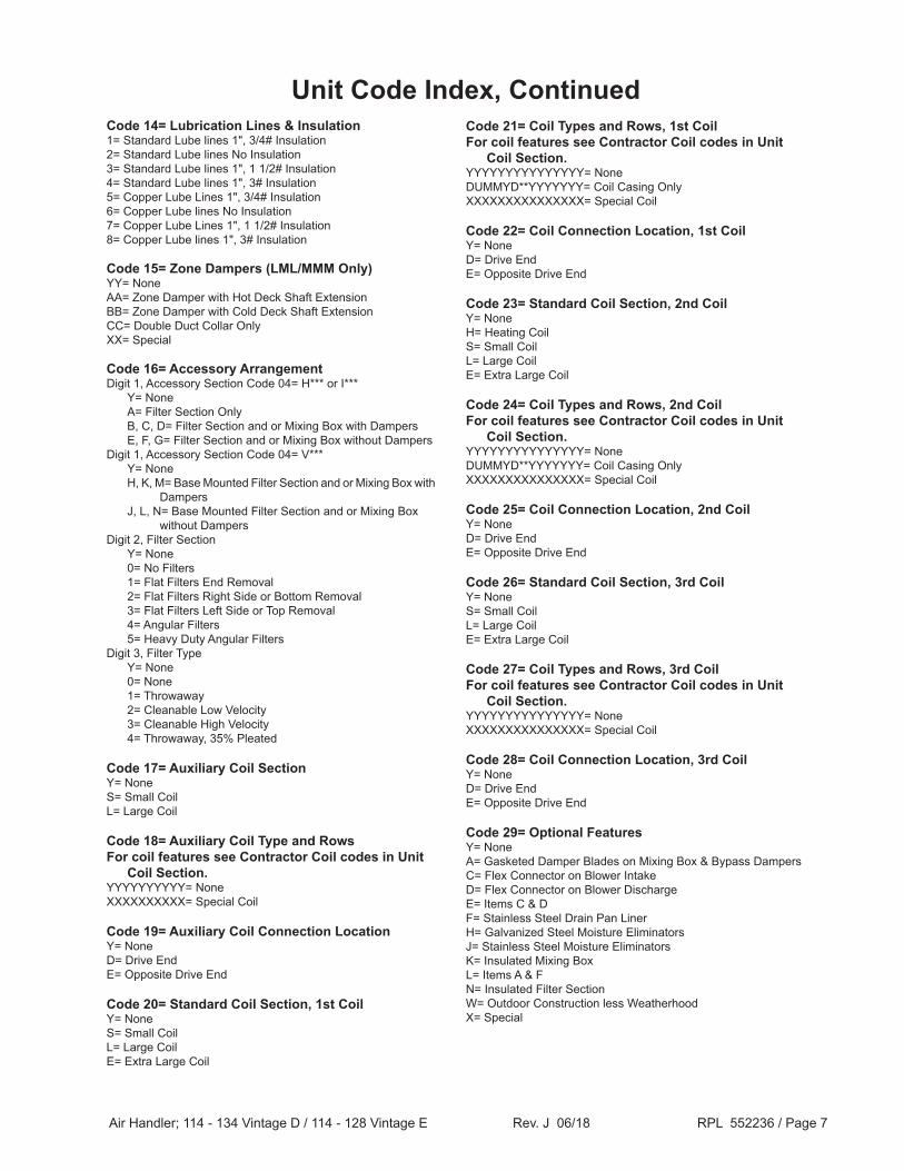
Code 14= Lubrication Lines & Insulation1= Standard Lube lines 1", 3/4# Insulation2= Standard Lube lines No Insulation3= Standard Lube lines 1", 1 1/2# Insulation4= Standard Lube lines 1", 3# Insulation5= Copper Lube Lines 1", 3/4# Insulation6= Copper Lube lines No Insulation7= Copper Lube Lines 1", 1 1/2# Insulation8= Copper Lube lines 1", 3# Insulation
Code 15= Zone Dampers (LML/MMM Only)YY= NoneAA= Zone Damper with Hot Deck Shaft ExtensionBB= Zone Damper with Cold Deck Shaft ExtensionCC= Double Duct Collar OnlyXX= Special
Code 16= Accessory Arrangement Digit 1, Accessory Section Code 04= H*** or I*** Y= None A= Filter Section Only B, C, D= Filter Section and or Mixing Box with Dampers E, F, G= Filter Section and or Mixing Box without DampersDigit 1, Accessory Section Code 04= V*** Y= None H, K, M= Base Mounted Filter Section and or Mixing Box with Dampers J, L, N= Base Mounted Filter Section and or Mixing Box without DampersDigit 2, Filter Section Y= None 0= No Filters 1= Flat Filters End Removal 2= Flat Filters Right Side or Bottom Removal 3= Flat Filters Left Side or Top Removal 4= Angular Filters 5= Heavy Duty Angular FiltersDigit 3, Filter Type Y= None 0= None 1= Throwaway 2= Cleanable Low Velocity 3= Cleanable High Velocity 4= Throwaway, 35% Pleated
Code 17= Auxiliary Coil SectionY= NoneS= Small CoilL= Large Coil
Code 18= Auxiliary Coil Type and Rows For coil features see Contractor Coil codes in Unit Coil Section.YYYYYYYYYY= NoneXXXXXXXXXX= Special Coil
Code 20= Standard Coil Section, 1st CoilY= NoneS= Small CoilL= Large CoilE= Extra Large Coil
Code 21= Coil Types and Rows, 1st Coil For coil features see Contractor Coil codes in Unit Coil Section.YYYYYYYYYYYYYYY= NoneDUMMYD**YYYYYYY= Coil Casing OnlyXXXXXXXXXXXXXXX= Special Coil
Code 23= Standard Coil Section, 2nd CoilY= NoneH= Heating CoilS= Small CoilL= Large CoilE= Extra Large Coil
Code 24= Coil Types and Rows, 2nd Coil For coil features see Contractor Coil codes in Unit Coil Section.YYYYYYYYYYYYYYY= NoneDUMMYD**YYYYYYY= Coil Casing OnlyXXXXXXXXXXXXXXX= Special Coil
Code 26= Standard Coil Section, 3rd CoilY= NoneS= Small CoilL= Large CoilE= Extra Large Coil
Code 27= Coil Types and Rows, 3rd Coil For coil features see Contractor Coil codes in Unit Coil Section.YYYYYYYYYYYYYYY= NoneXXXXXXXXXXXXXXX= Special Coil
Code 29= Optional FeaturesY= None A= Gasketed Damper Blades on Mixing Box & Bypass DampersC= Flex Connector on Blower Intake D= Flex Connector on Blower DischargeE= Items C & DF= Stainless Steel Drain Pan Liner H= Galvanized Steel Moisture Eliminators J= Stainless Steel Moisture EliminatorsK= Insulated Mixing BoxL= Items A & FN= Insulated Filter SectionW= Outdoor Construction less WeatherhoodX= Special
Unit Code Index, Continued
Air Handler; 114 - 134 Vintage D / 114 - 128 Vintage E Rev. J 06/18 RPL 552236 / Page 8
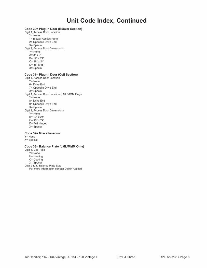
Code 30= Plug-In Door (Blower Section)Digit 1, Access Door Location Y= None 1= Blower Access Panel 2= Opposite Drive End X= SpecialDigit 2, Access Door Dimensions Y= None A= 8" x 9" B= 12" x 24" C= 18" x 24" D= 36" x 48" X= Special
Code 31= Plug-In Door (Coil Section)Digit 1, Access Door Location Y= None 6= Drive End 7= Opposite Drive End X= SpecialDigit 1, Access Door Location (LML/MMM Only) Y= None 8= Drive End 9= Opposite Drive End X= SpecialDigit 2, Access Door Dimensions Y= None B= 12" x 24" C= 18" x 24" D= Full Hinged X= Special
Code 32= Miscellaneous Y= NoneX= Special
Code 33= Balance Plate (LML/MMM Only)Digit 1, Coil Type Y= None H= Heating C= Cooling X= SpecialDigit 2 & 3, Balance Plate Size For more information contact Daikin Applied
Unit Code Index, Continued
Air Handler; 114 - 134 Vintage D / 114 - 128 Vintage E Rev. J 06/18 RPL 552236 / Page 9
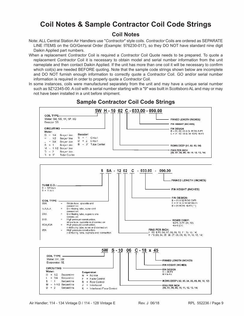
Coil Notes & Sample Contractor Coil Code Strings
Note: ALL Central Station Air Handlers use "Contractor" style coils. Contractor Coils are ordered as SEPARATE LINE ITEMS on the GO/General Order (Example: 976230-017), so they DO NOT have standard nine digit Daikin Applied part numbers.
When a replacement Contractor Coil is required a Contractor Coil Quote needs to be prepared. To quote a replacement Contractor Coil it is necessary to obtain model and serial number information from the unit nameplate and then contact Daikin Applied. If the unit has more than one coil it will be necessary to confirm which coil(s) are needed BEFORE quoting. Note that the sample code strings shown below are incomplete and DO NOT furnish enough information to correctly quote a Contractor Coil. GO and/or serial number information is required in order to properly quote a Contractor Coil.
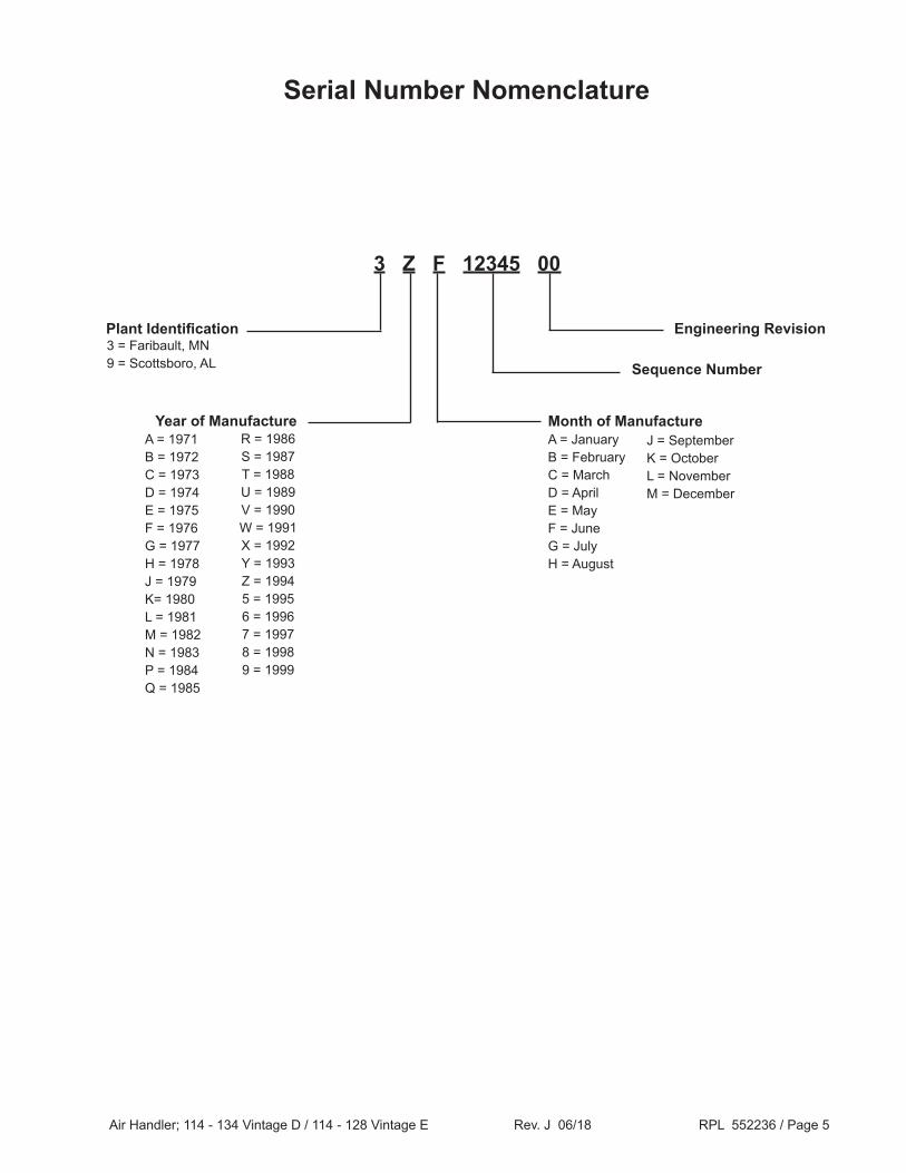
In some instances, coils were manufactured separately from the unit and may have a unique serial number such as 9Z12345-00. A coil with a serial number starting with a "9" was built in Scottsboro AL and may or may not have been installed in a unit before shipment.
Sample Contractor Coil Code Strings
Coil Notes
Air Handler; 114 - 134 Vintage D / 114 - 128 Vintage E Rev. J 06/18 RPL 552236 / Page 10
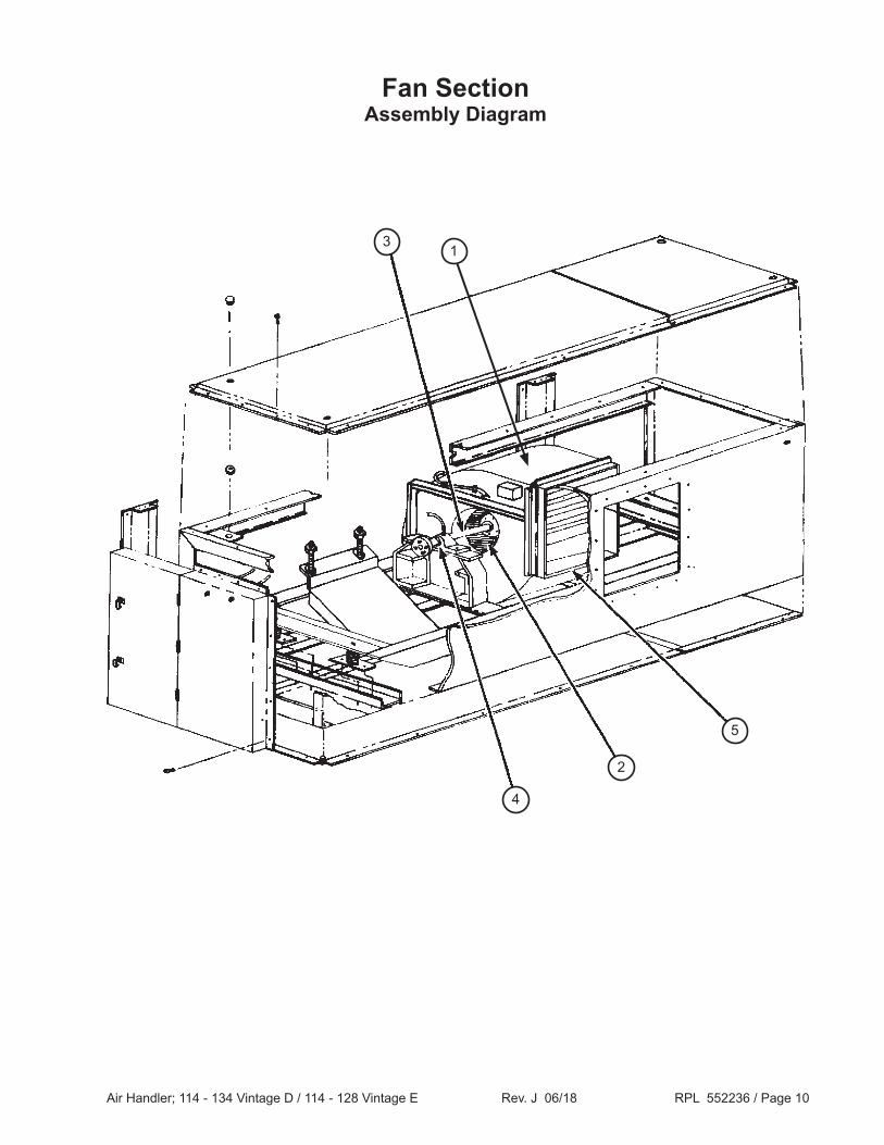
Fan SectionAssembly Diagram
1
5
3
2
4
Air Handler; 114 - 134 Vintage D / 114 - 128 Vintage E Rev. J 06/18 RPL 552236 / Page 11
1 Note: NO Damper Actuators, Actuator Linkage, sensors, OR controls were supplied with Central Station Air Handler units. If a field supplied item is required, contact Daikin Applied with vendor and vendor part number information to see if a suitable replacement can be obtained.
Air Handler; 114 - 134 Vintage D / 114 - 128 Vintage E Rev. J 06/18 RPL 552236 / Page 16
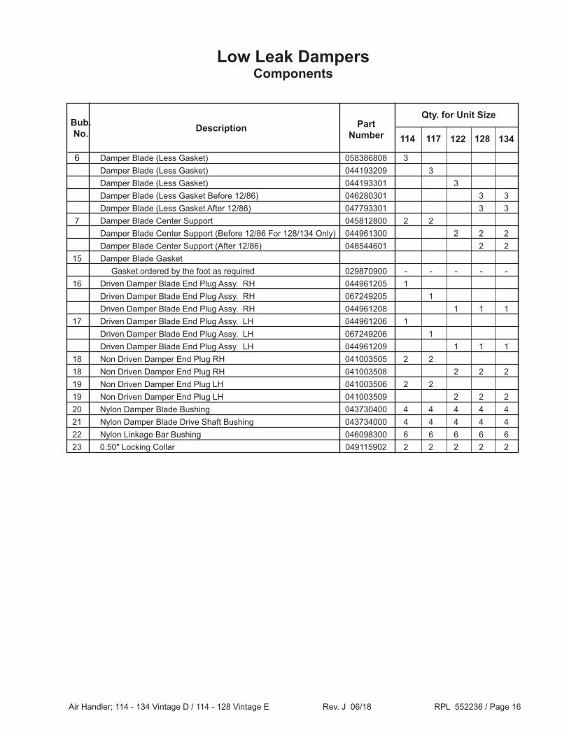
Low Leak DampersComponents
6 Damper Blade (Less Gasket) 058386808 3 Damper Blade (Less Gasket) 044193209 3 Damper Blade (Less Gasket) 044193301 3 Damper Blade (Less Gasket Before 12/86) 046280301 3 3 Damper Blade (Less Gasket After 12/86) 047793301 3 3 7 Damper Blade Center Support 045812800 2 2 Damper Blade Center Support (Before 12/86 For 128/134 Only) 044961300 2 2 2 Damper Blade Center Support (After 12/86) 048544601 2 2 15 Damper Blade Gasket Gasket ordered by the foot as required 029870900 - - - - - 16 Driven Damper Blade End Plug Assy. RH 044961205 1 Driven Damper Blade End Plug Assy. RH 067249205 1 Driven Damper Blade End Plug Assy. RH 044961208 1 1 1 17 Driven Damper Blade End Plug Assy. LH 044961206 1 Driven Damper Blade End Plug Assy. LH 067249206 1 Driven Damper Blade End Plug Assy. LH 044961209 1 1 1 18 Non Driven Damper End Plug RH 041003505 2 2 18 Non Driven Damper End Plug RH 041003508 2 2 2 19 Non Driven Damper End Plug LH 041003506 2 2 19 Non Driven Damper End Plug LH 041003509 2 2 2 20 Nylon Damper Blade Bushing 043730400 4 4 4 4 4 21 Nylon Damper Blade Drive Shaft Bushing 043734000 4 4 4 4 4 22 Nylon Linkage Bar Bushing 046098300 6 6 6 6 6 23 0.50" Locking Collar 049115902 2 2 2 2 2