TM 55-1945-205-10-2 TECHNICAL MANUAL OPERATORS MANUAL FOR MODULAR CAUSEWAY SYSTEM (MCS) ROLL-ON/ROLL-OFF DISCHARGE FACILITY(RRDF) RRDF-1 NSN 1945-01-473-2282 This manual supersedes TM 55-1945-205-10 dated 29 August 1997 including all changes. DISTRIBUTION STATEMENT A - Approved for public release, distribution is unlimited. HEADQUARTERS, DEPARTMENT OF THE ARMY 15 MAY 2002 FLOATING CAUSEWAY WARPING TUG CAUSEWAY FERRY ROLL-ON/ROLL-OFF DISCHARGE FACILITY LCU-2000 LSV
Transcript
1
TM 55-1945-205-10-2TECHNICAL MANUAL
OPERATORS MANUALFOR
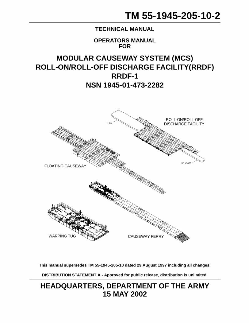
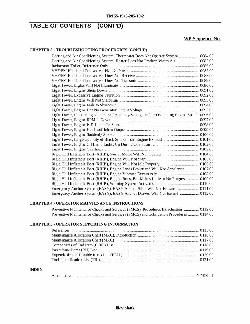
MODULAR CAUSEWAY SYSTEM (MCS)ROLL-ON/ROLL-OFF DISCHARGE FACILITY(RRDF)
RRDF-1NSN 1945-01-473-2282
This manual supersedes TM 55-1945-205-10 dated 29 August 1997 including all changes.
DISTRIBUTION STATEMENT A - Approved for public release, distribution is unlimited.
HEADQUARTERS, DEPARTMENT OF THE ARMY15 MAY 2002
FLOATING CAUSEWAY
WARPING TUG CAUSEWAY FERRY
ROLL-ON/ROLL-OFFDISCHARGE FACILITY
LCU-2000
LSV
TM 55-1945-205-10-2
HEADQUARTERSDEPARTMENT OF THE ARMY
WASHINGTON, D.C. 15 MAY 2002
TECHNICAL MANUAL
OPERATORS MANUALFOR
MODULAR CAUSEWAY SYSTEM (MCS) ROLL-ON/ROLL-OFF DISCHARGE FACILITY (RRDF)
RRDF-1NSN 1945-01-473-2282
Current as of 15 MAY 2002
This manual supersedes TM 55-1945-205-10 dated 29 August 1997 including all changes.
DISTRIBUTION STATEMENT A - Approved for public release; distribution is unlimited.
REPORTING ERRORS AND RECOMMENDING IMPROVEMENTS
You can help improve this publication. If you find any mistakes or if you know of a way to improve theprocedures, please let us know. Submit your DA Form 2028-2 (Recommended Changes to EquipmentTechnical Publications), through the Internet, on the Army Electronic Product Support (AEPS) website.The Internet address is http://aeps.ria.army.mil. If you need a password, scroll down and click on“ACCESS REQUEST FORM”. The DA Form 2028 is located in the ONLINE FORMS PROCESSINGsection of the AEPS website. Fill out the form and click on “SUBMIT”. Using this form on the AEPSwebsite will enable us to respond quicker to your comments and better manage the DA Form 2028program. You may also mail, E-mail or fax your letter, DA Form 2028, or DA Form 2028-2 directly to:Commander, U.S. Army Tank-Automotive and Armaments Command, ATTN: AMSTA-LC-CIP-WT, RockIsland, IL 61299-7630. The E-mail address is [email protected]. The fax number isDSN 793-0726 or Commercial (309) 782-0726.
TM 55-1945-205-10-2
TABLE OF CONTENTS
WP Sequence No.
WARNING SUMMARY
HOW TO USE THIS MANUAL
CHAPTER 1 - DESCRIPTION AND THEORY OF OPERATION
General Information .............................................................................................................. 0001 00Description and Data, Equipment Characteristics, Capabilities and Features ...................... 0002 00Description and Data, Location and Description of Major Components .............................. 0003 00Description and Data, Equipment Data ................................................................................. 0004 00Description and Data, Equipment Configuration .................................................................. 0005 00Theory of Operation .............................................................................................................. 0006 00
CHAPTER 2 - OPERATOR INSTRUCTIONS
Operator Controls and Indicators, Description and Use ........................................................ 0007 00Module ISOPAK, Preparation for Use .................................................................................. 0008 00Male and Female Guillotine Connectors, Preparation for Use .............................................. 0009 00D-Ring/Cloverleaf and Deck Cleat Fittings, Preparation for Use ......................................... 0010 00Module Strings, Preparation for Use ..................................................................................... 0011 00Intermediate Section, Preparation for Use ............................................................................. 0012 00Combination Beach/Sea End Section, Preparation for Use ................................................... 0013 00Segment, Preparation for Use ................................................................................................ 0014 00Platform, Preparation for Use ................................................................................................ 0015 00Mooring Bitts and Quick Disconnects, Preparation for Use ................................................. 0016 00Towing Bridle, Towing Interface and Towing Lights, Preparation for Use ......................... 0017 00Fenders, Preparation for Use ................................................................................................. 0018 00Safety Equipment, Lifeline and Dunnage Mats, Preparation for Use ................................... 0019 00Generator Container, Preparation for Use ............................................................................. 0020 00Personnel Shelter, Preparation for Use .................................................................................. 0021 00Emergency Anchoring System (EASY), Preparation for Use ............................................... 0022 00Light Towers, Preparation for Use ........................................................................................ 0023 00Rigid Hull Inflatable Boat (RHIB), Preparation for Use ....................................................... 0024 00Mooring Sealift Vessel Platform, Operating Procedures ...................................................... 0025 00EASY Mooring System, Operating Procedures .................................................................... 0026 00Tactical Quiet Generator, Operating Procedures ................................................................... 0027 00Generator Container Base Fuel Tank, Refueling, Operating Procedures .............................. 0028 00Generator Container, Transferring Fuel From Generator Container Base Fuel Tank To
Day Fuel Tank, Operating Procedures .................................................................... 0029 00Generator Container, Fire Suppression System, Operating Procedures ................................ 0030 00Personnel Shelter, Heating and Air Conditioning System, Operating Procedures ................ 0031 00Incinerator Toilet/Urinal Galley, Operating Procedures ....................................................... 0032 00Personnel Shelter VHF/FM Handheld Transceiver, Operating Procedures .......................... 0033 00Light Towers, Operating Procedures ..................................................................................... 0034 00Rigid Hull Inflatable Boat (RHIB) and Motor, Operating Procedures ................................. 0035 00Dunnage Mats, Preparation for Movement ........................................................................... 0037 00Light Towers, Preparation for Movement ............................................................................. 0038 00Emergency Anchoring System (EASY), Preparation for Movement ................................... 0039 00Personnel Shelter, Preparation for Movement ....................................................................... 0040 00
i
TM 55-1945-205-10-2
TABLE OF CONTENTS (CONT’D)
WP Sequence No.
CHAPTER 2 - OPERATOR INSTRUCTIONS (CONT’D)
Generator Container, Preparation for Movement .................................................................. 0041 00Fenders, Preparation for Movement ...................................................................................... 0042 00Safety Equipment, Preparation for Movement ...................................................................... 0043 00Towing Bridle, Towing Interface and Towing Lights, Preparation for Movement .............. 0044 00Mooring Bitts and Quick Disconnects, Preparation for Movement ...................................... 0045 00D-Ring/Cloverleaf and Deck Cleats Fittings, Preparation for Movement ............................ 0046 00Full and Force Opening Configurations, Preparation for Movement .................................... 0047 00Segment, Preparation for Movement ..................................................................................... 0048 00Combination Beach/Sea End Section, Preparation for Movement ....................................... 0049 00Intermediate Section, Preparation for Movement ................................................................. 0050 00Module Strings, Preparation for Movement .......................................................................... 0051 00Male and Female Guillotine Connectors, Preparation for Movement .................................. 0052 00Module ISOPAK, Preparation for Storage ............................................................................ 0053 00Tactical Quiet Generator, Emergency Stop, Emergency Procedures .................................... 0054 00Generator Container, Manual Operation of Tactical Quiet Generator Fire Suppression
Troubleshooting Procedures Index ........................................................................................ 0074 00Tactical Quiet Generator, Reference Only ............................................................................ 0075 00Generator Container, DC Lights Will Not Operate ............................................................... 0076 00Generator Container, Day Tank Fuel Level Indication System Is Inoperative ..................... 0077 00Generator Container, Manual Fuel Transfer Pump Will Not Prime ..................................... 0078 00Generator Container, Manual Fuel Transfer Pump Pumps Slowly ....................................... 0079 00Generator Container, Manual Fuel Transfer Pump Leaks ..................................................... 0080 00Generator Container, Electric Fuel Transfer Pump Inoperative ............................................ 0081 00Generator Container, Fire Suppression System Inoperative ................................................. 0082 00Heating and Air Conditioning System, Fan Does Not Operate Continuously When
Electrical Power Is Supplied To Personnel Shelter ................................................ 0083 00
ii
TM 55-1945-205-10-2
TABLE OF CONTENTS (CONT’D)
WP Sequence No.
CHAPTER 3 - TROUBLESHOOTING PROCEDURES (CONT’D)
Heating and Air Conditioning System, Thermostat Does Not Operate System .................... 0084 00Heating and Air Conditioning System, Heater Does Not Produce Warm Air ...................... 0085 00Incinerator Toilet, Reference Only ........................................................................................ 0086 00VHF/FM Handheld Transceiver Has No Power ................................................................... 0087 00VHF/FM Handheld Transceiver Does Not Receive .............................................................. 0088 00VHF/FM Handheld Transceiver Does Not Transmit ............................................................ 0089 00Light Tower, Lights Will Not Illuminate .............................................................................. 0090 00Light Tower, Engine Shuts Down ......................................................................................... 0091 00Light Tower, Excessive Engine Vibration ............................................................................ 0092 00Light Tower, Engine Will Not Start/Run .............................................................................. 0093 00Light Tower, Engine Fails to Shutdown ................................................................................ 0094 00Light Tower, Engine Has No Generator Output Voltage ...................................................... 0095 00Light Tower, Fluctuating Generator Frequency/Voltage and/or Oscillating Engine Speed 0096 00Light Tower, Engine RPM Is Down ...................................................................................... 0097 00Light Tower, Engine Is Difficult To Start ............................................................................. 0098 00Light Tower, Engine Has Insufficient Output ....................................................................... 0099 00Light Tower, Engine Suddenly Stops .................................................................................... 0100 00Light Tower, Large Quantity of Black Smoke from Engine Exhaust ................................... 0101 00Light Tower, Engine Oil Lamp Lights Up During Operation ............................................... 0102 00Light Tower, Engine Overheats ............................................................................................ 0103 00Rigid Hull Inflatable Boat (RHIB), Starter Motor Will Not Operate .................................... 0104 00Rigid Hull Inflatable Boat (RHIB), Engine Will Not Start ................................................... 0105 00Rigid Hull Inflatable Boat (RHIB), Engine Will Not Idle Properly ...................................... 0106 00Rigid Hull Inflatable Boat (RHIB), Engine Loses Power and Will Not Accelerate ............. 0107 00Rigid Hull Inflatable Boat (RHIB), Engine Vibrates Excessively ........................................ 0108 00Rigid Hull Inflatable Boat (RHIB), Engine Runs, But Makes Little or No Progress ........... 0109 00Rigid Hull Inflatable Boat (RHIB), Warning System Activates ........................................... 0110 00Emergency Anchor System (EASY), EASY Anchor Slide Will Not Elevate ...................... 0111 00Emergency Anchor System (EASY), EASY Anchor Drawer Will Not Extend ................... 0112 00
CHAPTER 4 - OPERATOR MAINTENANCE INSTRUCTIONS
Preventive Maintenance Checks and Services (PMCS), Procedures Introduction ............... 0113 00Preventive Maintenance Checks and Services (PMCS) and Lubrication Procedures ........... 0114 00
CHAPTER 5 - OPERATOR SUPPORTING INFORMATION
References ............................................................................................................................. 0115 00Maintenance Allocation Chart (MAC), Introduction ............................................................ 0116 00Maintenance Allocation Chart (MAC) .................................................................................. 0117 00Components of End Item (COEI) List ................................................................................... 0118 00Basic Issue Items (BII) List ................................................................................................... 0119 00Expendable and Durable Items List (EDIL) .......................................................................... 0120 00Tool Identification List (TIL) ................................................................................................ 0121 00
This manual contains certain features to improve the convenience of using this manual and increase the user’s efficiency. These features include:
a. Accessing Information
Information is accessed by referring to the Table of Contents, located in the front of this manual, or by looking in the Alphabetical Index, located in the back of this manual.
b. Illustrations
Various methods are used to locate and repair components. Locator illustrations in Controls and Indicator tables, PMCS tables, exploded views and cut-away diagrams make the information in the manual easier to understand and follow.
c. Using This Manual
When using this manual, read and understand the entire maintenance action before performing the task. Also, read and understand all warnings, cautions and notes as well as general safety precautions that apply to the task to be performed. The warning summary will inform personnel of hazards associated with the equipment to be worked on. However, the summary is not all inclusive and personnel should be aware at all times of hazardous conditions that may arise.
Prior to starting the procedures in this manual, the initial setup requirements are located directly above each procedure. The information is given to ensure all materials, expendables, tools and any other equipment necessary are readily available for use. The initial setup will be accomplished prior to starting the actual steps of each maintenance procedure.
Locating Major Components
Obtain the manual for the system to be worked on. Open to the Table of Contents located in the front of this manual. Find Chapter 1, Description and Theory of Operation. Under the chapter title you will find the work package titled Location and Description of Major Components. Turn to the work package indicated. This work package will give a brief description of the major components, and show an illustration of what the component looks like and its location.
The Alphabetical Index, located in the back of this manual, contains an alphabetical list of all sections of this manual. Location and Description of Major Components is found in section L. The work package is found on the right side of the title where the Location and Description of Major Components is located. Turn to the work package indicated to find the description and location of each component.
Operator Instructions
To locate an operator task, open the manual to the Table of Contents located in the front of this manual. Locate the procedure that is to be performed. Next to the procedure, on the right, locate the work package number. Turn to the work package number in the manual. Perform the initial setup by obtaining the expendables, tools, materials and other items listed prior to starting the task. Perform the listed steps in order. The Alphabetical Index can also be used to locate the item and procedures to follow.
Tools: Lists all tools (standard or special) required to perform the task. Tools are identified with an item number and work package number from the Tool Identification List located in Chapter 4, Supporting Information.
Materials/Parts: Lists all parts or materials necessary to perform the task. Expendable and durables are identified with an item number from the applicable work package located in Chapter 4, Supporting Information.
Personnel Required: Lists all personnel necessary to perform the task.
v
TM 55-1945-205-10-2
Equipment Condition: Notes the conditions that must exist before starting the task. The equipment condition will also include any prerequisite maintenance tasks to be performed with reference to the work package number or to the TM number.
References: Includes any other manuals necessary to complete the task. When there are no references listed, all steps necessary to complete the task are contained within this manual. A listing of reference materials is contained in the work package References in Chapter 4, Supporting Information.
Location of Controls and Indicators
To locate a particular control and/or indicator, open the manual to the Table of Contents located in the front of the manual. Find Chapter 2, Operator Instructions. Locate the work package titled Description and Use of Operator Controls and Indicators. Turn to the work package indicated. Locate the control and, or indicator that you are attempting to identify. Take note of the number pointing to the control or indicator. Refer to the table below the picture and find the number in the column on the far left hand side. Reading from left to right, find the number that matches the number from the picture, then read the name of the control/indicator and following function of the item, as detailed in the far right hand column.
Troubleshooting Procedures
The Table of Contents or Alphabetical Index may be used to locate sections within this manual. To locate a particular troubleshooting procedure, open the manual to the Table of Contents located in the front of this manual. Find Chapter 3, Troubleshooting Procedures. Under this section, find a work package titled Troubleshooting Index. Turn to the work package indicated, which lists all of the troubleshooting procedures. Look down the list until you find the appropriate work package for the problem you are trying to solve. To the right side of the procedure will be a work package number. Turn to the work package indicated and follow the steps to complete the troubleshooting procedure. The procedures list the malfunction, symptom and the corrective action. The corrective action will indicate which maintenance procedure to go to for the repair of the symptom or what level of maintenance is capable of repair of the problem. Follow the procedures indicated to complete the task. At the top of the task you will have a section called INITIAL SETUP. There are five basic headings listed under INITIAL SETUP.
Test Equipment: Lists all test equipment (standard or special) required to troubleshoot, test and inspect the equipment covered in this manual. The test equipment is identified with an item number and work package number from the Tool Identification List located in Chapter 4, Supporting Information.
Tools: Lists all tools (standard or special) required to perform the task. Tools are identified with an item number and work package number from the Tool Identification List located in Chapter 4, Supporting Information.
Personnel Required: Lists all personnel necessary to perform the task.
Equipment Condition: Notes the conditions that must exist before starting the task. The equipment condition will also include any prerequisite maintenance tasks to be performed with reference to the work package number or to the TM number.
References: Includes any other manuals necessary to complete the task. When there are no references listed, all steps necessary to complete the task are contained within this manual. A listing of reference materials is contained in the work package References in Chapter 4, Supporting Information.
Maintenance Instructions
To locate a maintenance procedure, open the manual to the Table of Contents located in the front of this manual. Find Chapter 4, Maintenance Instructions. Look down the list and find the maintenance procedure to be accomplished. On the right side of the maintenance procedure will be a work package number. Turn to the work package indicated.
vi
TM 55-1945-205-10-2
Before beginning the maintenance task, look through the procedure to familiarize yourself with the entire maintenance procedure. At the top of the task you will have a section called INITIAL SETUP. There are five basic headings listed under INITIAL SETUP.
Tools: Lists all tools (standard or special) required to perform the task. Tools are identified with an item number and work package number from the Tool Identification List located in Chapter 4, Supporting Information.
Materials/Parts: Lists all parts or materials necessary to perform the task. Expendable and durables are identified with an item number from the applicable work package located in Chapter 4, Supporting Information.
Personnel Required: Lists all personnel necessary to perform the task.
References: Includes any other manuals necessary to complete the task. When there are no references listed, all steps necessary to complete the task are contained within this manual. A listing of reference materials is contained in the work package References in Chapter 4, Supporting Information.
Equipment Condition: Notes the conditions that must exist before starting the task. The equipment condition will also include any prerequisite maintenance tasks to be performed with reference to the work package number or to the TM number.
Test Equipment: Lists all test equipment (standard or special) required to troubleshoot, test and inspect the equipment covered in this manual. The test equipment is identified with an item number and work package number from the Tool Identification List located in Chapter 4, Supporting Information.
vii/viii blank
TM 55-1945-205-10-2
1
CHAPTER 1
DESCRIPTION AND THEORY OF OPERATIONFOR
MODULAR CAUSEWAY SYSTEM (MCS) ROLL-ON/ROLL-OFF DISCHARGE FACILITY (RRDF)
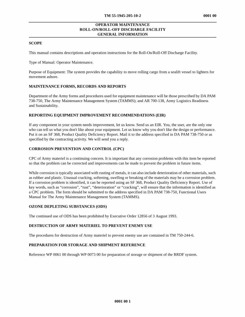
This manual contains descriptions and operation instructions for the Roll-On/Roll-Off Discharge Facility.
Type of Manual: Operator Maintenance.
Purpose of Equipment: The system provides the capability to move rolling cargo from a sealift vessel to lighters for movement ashore.
MAINTENANCE FORMS, RECORDS AND REPORTS
Department of the Army forms and procedures used for equipment maintenance will be those prescribed by DA PAM 738-750, The Army Maintenance Management System (TAMMS); and AR 700-138, Army Logistics Readiness and Sustainability.
If any component in your system needs improvement, let us know. Send us an EIR. You, the user, are the only one who can tell us what you don't like about your equipment. Let us know why you don't like the design or performance. Put it on an SF 368, Product Quality Deficiency Report. Mail it to the address specified in DA PAM 738-750 or as specified by the contracting activity. We will send you a reply.
CORROSION PREVENTION AND CONTROL (CPC)
CPC of Army materiel is a continuing concern. It is important that any corrosion problems with this item be reported so that the problem can be corrected and improvements can be made to prevent the problem in future items.
While corrosion is typically associated with rusting of metals, it can also include deterioration of other materials, such as rubber and plastic. Unusual cracking, softening, swelling or breaking of the materials may be a corrosion problem. If a corrosion problem is identified, it can be reported using an SF 368, Product Quality Deficiency Report. Use of key words, such as “corrosion”, “rust”, “deterioration” or “cracking”, will ensure that the information is identified as a CPC problem. The form should be submitted to the address specified in DA PAM 738-750, Functional Users Manual for The Army Maintenance Management System (TAMMS).
OZONE DEPLETING SUBSTANCES (ODS)
The continued use of ODS has been prohibited by Executive Order 12856 of 3 August 1993.
DESTRUCTION OF ARMY MATERIEL TO PREVENT ENEMY USE
The procedures for destruction of Army materiel to prevent enemy use are contained in TM 750-244-6.
PREPARATION FOR STORAGE AND SHIPMENT REFERENCE
Reference WP 0061 00 through WP 0073 00 for preparation of storage or shipment of the RRDF system.
EQUIPMENT CHARACTERISTICS, CAPABILITIES AND FEATURES
The roll-on/roll-off discharge facility (RRDF) is a floating discharge platform for ocean-going roll-on/roll-off sealift vessels. It provides the capability to move rolling cargo from the sealift vessel to lighters for movement ashore. The RRDF platform consists of an assembly of 153 non-powered floating modules. These modules are assembled into five sub-assemblies, which are then connected together using the Navy flexor and shear connector system which forms a hinge joint between them. The five sub-assemblies are 80 ft long and of differing widths. The width depends on the sub-assemblies location in the platform and on whether the RRDF platform will be used at the side ramp or the stern ramp of the sealift vessel. The overall dimensions of the RRDF platform are 400 ft long by 120 ft wide.
The RRDF is maneuvered into place, either alongside or astern of the sealift vessel, by warping tugs. It is secured to the sealift vessel in position for the stern or the side ramp to land on the platform.
Up to two Landing Ships Vehicle (LSV) or two Landing Craft Utility (LCU) watercraft lighters can be loaded at a time from an RRDF platform. In addition, the platform is capable of supporting two M-1 Abrams tanks and one sealift vessel cargo ramp foot on the platform surface. The structure of the RRDF will withstand the cargo loading through Sea State 2 conditions.
The RRDF consists of up to 17 intermediate modular sections. Intermediate sections consist of three center modules and six rake end modules (two center rake modules, two right-hand rake modules and two left-hand rake modules). Other major components of the RRDF are the personnel shelter, diesel generator set, trailer-mounted light towers, lifeline subsystem, communications equipment, rigid hull inflatable boat (RHIB) and the emergency anchoring system (EASY).
LSV
LCU -2000
TM 55-1945-205-10-2
0002 00 2
0002 00
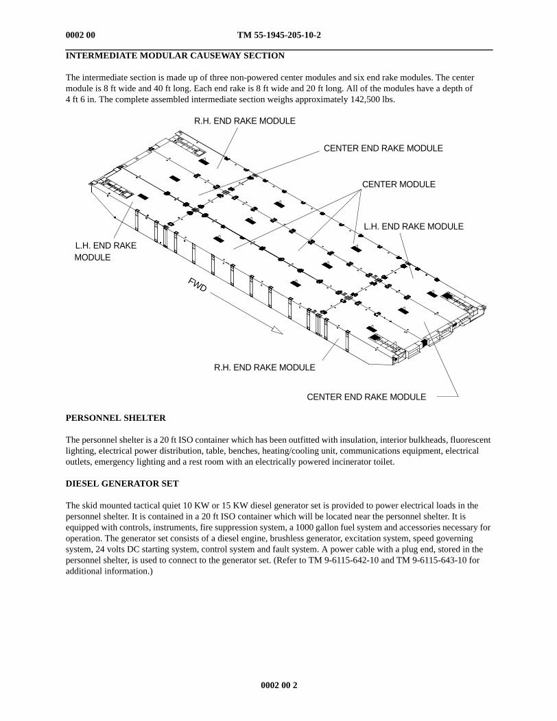
INTERMEDIATE MODULAR CAUSEWAY SECTION
The intermediate section is made up of three non-powered center modules and six end rake modules. The centermodule is 8 ft wide and 40 ft long. Each end rake is 8 ft wide and 20 ft long. All of the modules have a depth of4 ft 6 in. The complete assembled intermediate section weighs approximately 142,500 lbs.
PERSONNEL SHELTER
The personnel shelter is a 20 ft ISO container which has been outfitted with insulation, interior bulkheads, fluorescentlighting, electrical power distribution, table, benches, heating/cooling unit, communications equipment, electricaloutlets, emergency lighting and a rest room with an electrically powered incinerator toilet.
DIESEL GENERATOR SET
The skid mounted tactical quiet 10 KW or 15 KW diesel generator set is provided to power electrical loads in thepersonnel shelter. It is contained in a 20 ft ISO container which will be located near the personnel shelter. It isequipped with controls, instruments, fire suppression system, a 1000 gallon fuel system and accessories necessary foroperation. The generator set consists of a diesel engine, brushless generator, excitation system, speed governingsystem, 24 volts DC starting system, control system and fault system. A power cable with a plug end, stored in thepersonnel shelter, is used to connect to the generator set. (Refer to TM 9-6115-642-10 and TM 9-6115-643-10 foradditional information.)
R.H. END RAKE MODULE
L.H. END RAKEMODULE
CENTER END RAKE MODULE
CENTER MODULE
L.H. END RAKE MODULE
R.H. END RAKE MODULE
CENTER END RAKE MODULE
FWD
TM 55-1945-205-10-2
0002 00 3
0002 00
LIGHTING SYSTEM
The RRDF lighting system consists of four trailer-mounted light towers which are stowed in two 20 ft ISO containers. Each light tower is powered by a 6 KW diesel generator and supports four metal-halide lamps. Each lamp delivers 1000 watts of light intensity. Lamps are a high pressure sodium bulbs with a NEMA 6 design for large area coverage. The aluminum reflector housings have tempered impact resistant glass lenses. The lamps come with weather resistant twist-lock connections for connecting floodlights to the light tower.
The light tower is a three-section telescoping mast which extends from 12 to 30 ft and has a rotation range of 360° with a position lock. The mast is easily extended with dual hand-operated winches that incorporate an automatic safety brake. The tower retracts and stows horizontally for travel.
The light system comes with a 30 gallon translucent polyethylene fuel tank, single point lifting bail, forklift slots, heavy-duty outriggers, leveling indicator and removable drawbar. The control panel comes with one GFI protected, 120 volt, 20 amp duplex receptacle; one 240 volt, 25 amp receptacle; individual lamp switches and a non-resettable hourmeter to track records for periodic maintenance.
The overall length is (in./cm) 174/442, width is (in./cm) 79/201, height is (in./cm) 89/226 (travel position), standard tower height is (ft/m) 30/9 and shipping weight is (lb/kg) 2010/912.
LIFELINE SUBSYSTEM
The lifeline subsystem is installed along the sides of the RRDF platform to protect personnel from falls overboard. The stanchions for the lifelines are installed in the turn-tube fittings and ISO corner fittings of the section modules. The lifelines are installed on the inboard side of the lifeline stanchion. Chain is used to span the gap between the sections.
COMMUNICATIONS EQUIPMENT
The communications equipment consists of eight VHF/FM handheld transceivers. The transceivers have a frequency range of 156.025 to 163.275 mhz. All channels currently allocated in the USA, Canadian and International channels are available for use, plus ten weather channels.
The VHF/FM handheld transceiver has an RF power output with the CNB350 battery of 5.0 watts (high) and 1.0 watts (low). The operating voltage is 7.2 volts DC. The current drain in standby mode is 40 ma, in receive mode 200 ma, in the transmit mode 1.8 amps (high power) and 0.7 amps (low power). The battery life (5% Tx, 5% rcv, 90% standby) is approximately 10 hrs (high) and 15 hrs (low).
The dimensions of the unit are 5.51in. H X 2.1in. W X 1.50 in. D. The weight is 1.0 lb.
The transmitter has a conducted spurious emissions of 65 dB (high) and 55 dB (low). The audio response is within +2/-8 of 6 dB/octave pre-emphasis characteristic from 300 hz to 3000 hz. The AF Harmonic Distortion of the transmitter is 3%. The transmitter has a hum and noise rating of 37 dB and a frequency stability (-20°C to +50°C) of + 0.0005%.
The receiver has a sensitivity rating of 20 dB quieting at 0.35 uv and 12 dB SINAD at 0.30 uv. The squelch sensitivity (threshold) is 0.20 uv. Modulation acceptance bandwidth is + 4.5 khz receiver selectivity: spurious and image, rejection 60 dB, intermodulation regulation 60 dB and channel spacing 25 khz.
RIGID HULL INFLATABLE BOAT
The rigid hull inflatable boat, which is stored in 20 ft ISO containers, provides transportation for the crew of the RRDF. It has a seven person capacity and is fitted with a 70 horsepower gasoline outboard motor. The boat is approximately 15 ft 5 in. (4.70 m) long and has a beam of 6 ft 7 in. (2.01 m). The inflatable tube has a diameter of 20 in. Lifting weight is approximately 1000 lbs. The max loading capacity for the boat is 1903 lbs.
TM 55-1945-205-10-2
0002 00 4
0002 00
EMERGENCY ANCHORING SYSTEM (EASY)
The EASY is provided to anchor the RRDF platform in the event that the sealift vessel(s) departs the operating area due to weather or some other contingency. It is designed to hold the RRDF platform in its anchored position through Sea State 4 conditions. In more severe conditions, the EASY will control the drift of the platform.
The EASY is housed in a 20 ft ISO container which is placed and secured on the deck of the RRDF near the forward edge. The container is 20 ft long, 8 ft wide and 8 ft 5 in. high. The container is a full access container, which means that both sides and both ends of container open to give full access to the interior.
The mooring consists of one 2400 lbs NAVMOOR anchor, 200 ft of 2½ in. stud link chain and 500 ft of 10 in. circumference nylon line with a two-leg, 10 in. circumference nylon bridle.
DECK MATTING
The deck matting is used as dunnage and is placed where the cargo ramps of the sealift vessel and the lighters will land on the RRDF deck. The individual mats are a high density polyethylene material and are approximately 10 ft long, 4 ft wide and 1½ in. thick. Each mat weighs 300 lbs.
DECK CLEAT AND D-RING/CLOVERLEAF FITTINGS
The modular sections are provided with deck fittings to meet various operational needs. These fittings have a 15,000 lb load capacity and are inserted into the tube turns. There are ten tube turns per non-powered module and five per end rake.
MOORING BITT
The mooring bitts provide securing points on the RRDF platform for lighters and for fenders. They attach to the platform at the module connector locks. The bitts are designed for up to a 6 in. circumference mooring line. The mooring bitts are lifted and installed using the forklift adaptor. Each bitt weighs 235 lbs and is 6 ft 5 in. long. Thirty mooring bitts are provided with the RRDF system.
FENDERS (WITH ATTACHMENT CHAINS)
Their are four types of fenders authorized for use on the RRDF: 6 ft X 12 ft (Yokohama), 5 ft X 10 ft, 4 ft X 12 ft and 3 ft X 5 ft. The 6 ft X 12 ft fender (Yokohama) weighs approximately 4500 lbs with chain and tire net. The 5 ft X 10 ft fender weighs approximately 1500 lbs. The 4 ft X 12 ft fender weighs approximately 1450 lbs. The 3 ft X 5 ft fender weighs approximately 300 lbs.
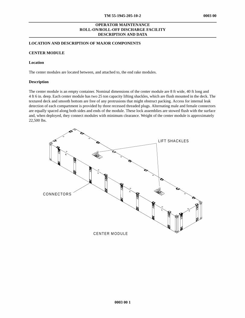
The center modules are located between, and attached to, the end rake modules.
Description
The center module is an empty container. Nominal dimensions of the center module are 8 ft wide, 40 ft long and 4 ft 6 in. deep. Each center module has two 25 ton capacity lifting shackles, which are flush mounted in the deck. The textured deck and smooth bottom are free of any protrusions that might obstruct packing. Access for internal leak detection of each compartment is provided by three recessed threaded plugs. Alternating male and female connectors are equally spaced along both sides and ends of the module. These lock assemblies are stowed flush with the surface and, when deployed, they connect modules with minimum clearance. Weight of the center module is approximately 22,500 lbs.


![Menu 2015.pdfRM12 [N] Dishes with nuts ohol Sushi Roll + SPICY SEAFOOD ROLL + DRAGON ROLL IA) DEEP-FRIED SOFT SHELL CRAB ROLL CALIFORNIA ROLL SALMON SKIN ROLL IA) UNAGI ROLL RM47 RM53](https://static.documents.pub/doc/80x56/5ed75f27acc46829cb3402b3/menu-2015pdf-rm12-n-dishes-with-nuts-ohol-sushi-roll-spicy-seafood-roll-dragon.jpg)


