27
MCTC manual MCNumera Software version : 2.12.x Manual revision : rev.01 Language : ENG Date : August 2021

MCTC manual
MCNumera
Software version : 2.12.x Manual revision : rev.01 Language : ENG Date : August 2021

2 MCTC manual
Index 1 Introduction 3
Symbols 3 Terms 3 Transport 3 Receipt 3 Disclaimer 3
2 General information 4 Safety 4 Certification 4 Operating environmental conditions 4
3 MCNumera 5 Introduction 5 MCNumera component overview 6
3.2.1 MCNumera System overview 6 3.2.2 MCNumera 7 3.2.3 Tube support 7 3.2.4 Reinforced plate 7
Mechanical installation 8 MCNumera electrical installation 9
4 General operation 10 The Interface 10
4.1.1 MCTC Touchscreen 10 4.1.2 MC-BC Blind controller 11
Start-up & Login 12 4.2.1 Configuration wizard 12 4.2.2 Home screen 12 4.2.3 Help function 13 4.2.4 User levels 13 4.2.5 Customer Support 14
The MCTC production screen 15 4.3.1 MCNumera single component 15 4.3.2 MCNumera multicomponent 15
5 MCNumera operation 16 MCNumera component configuration 16 Loadcell calibration 16 Material files 17
5.3.1 How to create a material file: 17 5.3.2 Selecting a material file 18
Starting/stopping the unit 18 MCNumera maintenance 19
6 Outputs 20
APPENDIX A: MCTC Technical Specifications 21
APPENDIX B: MCTC Dimensional drawing 22
APPENDIX C: MCNumera Dimensional drawing 23
APPENDIX D: Cleaning of MCNumera 24
APPENDIX E: Electrical diagram 25
APPENDIX F: Declaration of conformity 26

3 MCTC manual
1 Introduction Thank you for purchasing a Movacolor metering device. This manual is addressed to operators and qualified technicians taking care of the metering of dry additives to ensure correct use of the Movacolor dosing unit. This manual must be read before installing the dosing unit. Keep this manual in a place accessible for all operators.
Symbols
Important note.
Attention; safety regulations for the operator.
Terms
Operator: A person charged to operate, adjust, maintain and clean the machine. Qualified Technician: A specialized, suitable trained person authorized to execute the installation,
non-routine maintenance, or repairs requiring special knowledge of the machine and how it operates.
Multi component: Two or more dosing systems on one machine.
Transport To protect the Movacolor unit against damage during transport, the unit is packed in a cardboard box filled with polyurethane foam. Delivery terms are Ex-Works Sneek, The Netherlands. Buyer is responsible for the transport. Movacolor cannot be held liable for any damage during transport.
Receipt Check the unit thoroughly upon receipt for damages or missing parts. Pass any remarks to the local agent or Movacolor within 8 days upon receipt of goods.
Disclaimer Movacolor does not warrant that the hardware or software will work properly in all environments and applications, and makes no warranty and representation, either implied or expressed, with respect to the quality, performance, merchantability or fitness for a particular purpose. Movacolor has made every effort to ensure that this user’s manual is accurate; Movacolor disclaims liability for any inaccuracies or omissions that may have occurred. Information in this user’s manual is subject to change without notice and does not represent a commitment on the part of Movacolor. Movacolor assumes no responsibility for any inaccuracies that may be contained in this user’s manual. Movacolor makes no commitment to update or keep the current information in this user’s manual, and reserves the right to make improvements to this user’s manual and/or to the products described in this user’s manual, at any time without notice. If you find information in this manual that is incorrect, misleading or incomplete, we would appreciate your comments and suggestions.

4 MCTC manual
2 General information
Safety
The equipment is only designed and may only be used for the dosing of dry additives.
Any use that is not in conformity with the instructions is considered improper and as such frees the manufacturer from any liability regarding damage to things and/or persons.
Before switching on the unit for the first time, ensure that the mains power voltage applied is between 95 and 250VAC.
Ensure that all parts are securely fixed to the extruder, injection molding machine or machine support.
Always switch off the Movacolor control cabinet and disconnect the mains power plug from electrical power before performing maintenance.
Dangerous voltages are present inside the control cabinet for up to 2 minutes after it has been
switched off. Always disconnect the main compressed air connection before performing maintenance.
Certification
The Movacolor dosing unit is designed and produced in conformity with the following European regulations:
1. standards for machinery (health, safety, environment). 2. EMC (electromagnetic compatibility). 3. 2006/42/EG. 4. RoHS.
Operating environmental conditions
1. The unit must be protected against weather conditions. 2. Operating temperature -20 to +70 degrees Celsius. 3. Protection class: IP-50.

5 MCTC manual
3 MCNumera
Introduction
The MCNumera is developed to measure the throughput of main material. The machine is made from stainless steel, with a unique feature that there is an option to connect any material tube. The MCNumera can be equipped with different types of loaders.

6 MCTC manual
MCNumera component overview 3.2.1 MCNumera System overview
1. Loader*
2. MCNumera
3. Main Hopper
4. MCBalance
5. Neckpiece
1
3
4
5
2

7 MCTC manual
3.2.2 MCNumera
1. Connection box
2. Loader platform
3. Indication lights
4. Tube support
3.2.3 Tube support The MCNumera is standard delivered with a customizable tube support. The tube support can be cut to the desired length.
3.2.4 Reinforced plate When the MCNumera is installed on a non-Movacolor system, the reinforced plate might be used.
1
3
2 4

8 MCTC manual
Mechanical installation
2x
> 10mm

9 MCTC manual
MCNumera electrical installation The MCTC or MCBC controller delivered together with the MCNumera is standard equipped with 3 connections:
• Mains power cable;
• Input cable;
• Signal cable with M12 (female) connector. Before switching on the unit for the first time, ensure the mains power voltage being applied is between 95 and 250Vac 50/60Hz;
In case of a multi component system, the controller can be equipped with an additional CAN bus cable to interconnect between the MCTC and other MCBC’s;
Be aware that the cables can be influenced by external circumstances as electromagnetic fields;
Mount the controller on a place which is free of vibrations and within the specified temperature range.
The MCNumera is standard equipped with 2 connections:
• Loadcell connector;
• Signal cable with M12 (male) connector. Optional are:
• Alarm flash light, complete with cable;
• Compressed air solenoid valve complete with cable (for automatic hopper loader).
10 MCTC manual
4 General operation
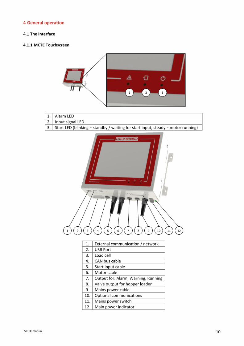
The Interface 4.1.1 MCTC Touchscreen
1. Alarm LED
2. Input signal LED
3. Start LED (blinking = standby / waiting for start input, steady = motor running)
1. External communication / network
2. USB Port
3. Load cell
4. CAN bus cable
5. Start input cable
6. Motor cable
7. Output for: Alarm, Warning, Running
8. Valve output for hopper loader
9. Mains power cable
10. Optional communications
11. Mains power switch
12. Main power indicator
3 2 1
2 3 4 5 6 7 11 9 8 10 1 12

11 MCTC manual
4.1.2 MC-BC Blind controller The image below shows the MC-BC in a standard configuration. In multicomponent or remote setups, refer to chapter Multicomponent.
1. Load cell
2. CAN bus cable
3. Motor cable
4. Valve output for hopper loader
5. Mains power cable
6. Mains power switch
7. Mains power indicator
7 6 5 4 3 2 1

12 MCTC manual
Start-up & Login After switching on the mains power of the MCTC, the screen will remain black for about 15 seconds, followed by various loading screens. After about 90 seconds the home screen appears. When the unit is used for the first time, a Configuration Wizard appears. 4.2.1 Configuration wizard When the machine is powered up for the first time a configuration wizard will pop up. In this wizard, the date/time can be set and a load cell calibration can be done for each unit. For the loadcell calibration, it is necessary to have the unit(s) installed as they will be during production, but not yet filled with material.
4.2.2 Home screen
Single component Multi component

13 MCTC manual
4.2.3 Help function
On most screens and popups a button is available. By pressing this button a new window will open with context sensitive information. 4.2.4 User levels The MCTC controller has three user levels, each level has other rights to access or change functions and/or options. The three user levels are: Operator, Tooling and Supervisor For changing to another user level, press on the menu icon (left bottom corner) and the user button appears. When pressing the user button, the login menu is entered. Press the LOGIN button and enter the password (4 numerals) and confirm. The passwords for the Tooling and Supervisor user levels can be defined by the supervisor in the “System Configuration” menu.
The accessible menus and settings per user level are shown in the table below. For some settings, the rights can be configured in the Login rights configuration menu. For “Operator” and “Tooling” level, some functionality is limited. These limitations can be found in the corresponding chapter.
User Level
Menu access Operator Tooling Supervisor
Login Component configuration Active alarms Consumption USB options Advanced settings
System configuration Materials Configurable
Select/Load recipes
Production parameters
Open tools form
Disable filling systems
Change dosing tool by recipe
System start/stop
Change/reset consumption
Forgot your supervisor password? Contact Movacolor service to retrieve an overall supervisor password. When entering a wrong password the user level will be set automatically to operator level. Screen time out: After 180 seconds (default setting) of inactivity the system will automatically logout to Start login level and the home-screen will be shown. The Time out time and Start login level can be set in the configuration menu.

14 MCTC manual
4.2.5 Customer Support Supervisor login required
From software version 2.11.x onward Customer Support is available. This is an online service which makes it possible to get remote support from a support employee. To use this function, the MCTC needs to be connected to the internet via the ethernet port on the MCTC. The connection between the MCTC and the remote server is entirely secured using several encryption and authentication techniques and thus can be used safely. No data will be saved to the remote support servers. Once the MCTC is connected to the remote server, a 3-digit ID will be displayed on this screen. A support employee will ask for this ID as it's used to identify the MCTC. When pressing the Customer Support button, a new window is opened.
Connect/Cancel (1) Connects the MCTC to the remote server. Make sure the MCTC meets the usage requirements. After pressing the connect button, but before the MCTC is connected, this button can be used to cancel the active connection attempt. Keep Connected (2) When this option is enabled, the MCTC will reconnect automatically when the connection is lost. Code (3) 3-digit ID to be communicated to the support employee to establish a connection. Disconnect (4) Disconnects the MCTC from the remote server. The ethernet cable can be safely removed after this if it is undesirable to stay connected to the internet at all times.
4
2
1
3
15 MCTC manual
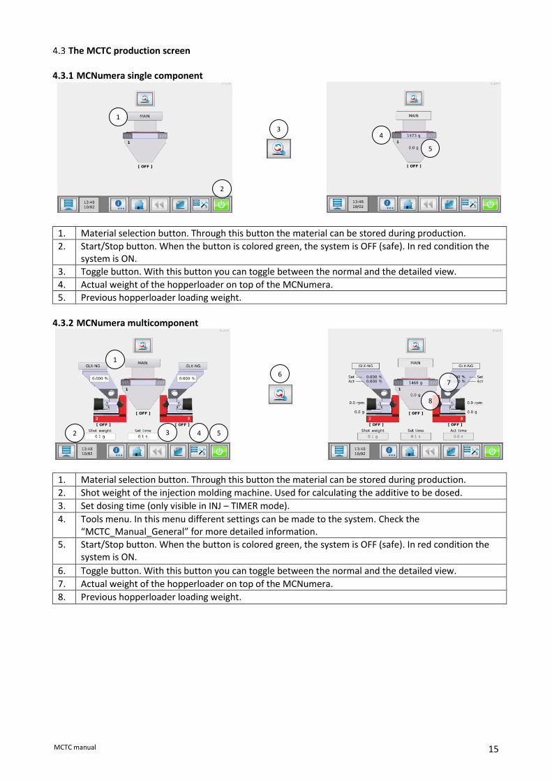
The MCTC production screen 4.3.1 MCNumera single component
1. Material selection button. Through this button the material can be stored during production.
2. Start/Stop button. When the button is colored green, the system is OFF (safe). In red condition the system is ON.
3. Toggle button. With this button you can toggle between the normal and the detailed view.
4. Actual weight of the hopperloader on top of the MCNumera.
5. Previous hopperloader loading weight.
4.3.2 MCNumera multicomponent
1. Material selection button. Through this button the material can be stored during production.
2. Shot weight of the injection molding machine. Used for calculating the additive to be dosed.
3. Set dosing time (only visible in INJ – TIMER mode).
4. Tools menu. In this menu different settings can be made to the system. Check the “MCTC_Manual_General” for more detailed information.
5. Start/Stop button. When the button is colored green, the system is OFF (safe). In red condition the system is ON.
6. Toggle button. With this button you can toggle between the normal and the detailed view.
7. Actual weight of the hopperloader on top of the MCNumera.
8. Previous hopperloader loading weight.
1
2
5
4 3
1
2 3 4 5
6 7
8

16 MCTC manual
5 MCNumera operation
MCNumera component configuration When the MCNumera is used for the first time it needs to be configured. Only the loadcells can be calibrated.
In multicomponent setups, it can be necessary to use the buttons to select the unit which has to be configured.
Loadcell calibration When the MCNumera is used for the first time, or a system setup change took place, a loadcell calibration is needed. Before a calibration is performed, make sure the points below are covered:
• The unit must be mounted horizontally (water levelled);
• Avoid vibrations during the load cell calibration. This will influence the calibration;
• Do not touch the unit during load cell calibration;
• Any material tubes should be fixed properly. To start the loadcell calibration sequence, go to the Load Cell menu:
Follow the steps from the menu, make sure to use two reference weights of 500g each. Each weight should be placed above a loadcell (see image below).
To verify the calibration, use the check function:
Check if:
• The weight is 1000g when the weights are positioned in different positions on the top plate. (always opposite to each other)
• The weight goes back to 0 when the reference weights are removed.

17 MCTC manual
Material files For the MCNumera, it is possible to name the material which is used in a process. This can be useful when consumption reports are generated. 5.3.1 How to create a material file: Supervisor or tooling login required
1. Press the material selection on the production screen ( 1 )
2. Press the “New Material” button: 3. Enter a material name and press the “Accept” button.
1

18 MCTC manual
5.3.2 Selecting a material file Supervisor or tooling login required
When more material file calibrations have been made, a file can be loaded to the device. To do this:
• In a multi component setup, select from the home screen the component to load the material on;
• Press the material selection button ( 1 );
• Select with the up and down buttons the required material name and confirm.
When there is a long list of stored materials, it can be time consuming to find the material. It is possible to search in the list of materials by using the search button. You can enter part of the
material name you need to search for. Example; you need to load the material named “pp-color-145”. When you enter “pp” in the search field, al material names containing “pp” will be displayed in the list.
Deleting materials can be done by selecting it from the material list followed by the delete selected button. Delete all materials can be done by pressing the delete all button.
Renaming materials can be done by selecting it from the material list followed by the rename selected button.
To go back to the production menu without selecting a material from the list press the cancel button.
Starting/stopping the unit When the right material is selected, the MCNumera can be started or stopped by pressing the (start/stop)
button.
1

19 MCTC manual
MCNumera maintenance To keep the MCNumera functioning correctly, it is advised to perform regular maintenance.
Always switch off the control cabinet and disconnect the mains power plug from electrical power before performing maintenance.
Always disconnect the main compressed air connection before performing maintenance.
Monthly
• Perform a weight check as described in the load cell calibration chapter;
• Clean the inside of the MCNumera (see instruction in appendix)

20 MCTC manual
6 Outputs For the location of the output connections, see appendix Electrical diagram. Alarm / Warning Output Connection 27 and 28. Warning event: this output is on (24V), the system continues running). Alarm event: this output is on (24V), the system stops running. Free programmable events can be programmed to an Alarm or Warning. See chapter: Events. Valve Output Connection 29 and 30. This output is on (24V) to start the hopper loader or open the knife gate. Alarm Output (OUT-1) Normally open contact, connection 32 and 33. Normally closed contact, connection 32 and 34. Alarm event: this output is activated, the systems stops running. Run Output (OUT-2) Normally open contact, connection 35 and 36. The “RUN signal” can be used as a Start/Stop condition for the molding machine. For example: Molding machine can only start in case dosing unit is also started. Default the Run output 2 (OUT-2) is always on in production mode (status Dosing or Standby) Production status = STANDBY or DOSING → output 35 and 36 is CLOSED. Production status = OFF → output 35 and 36 is OPEN. In case of alarm, the alarm output (OUT-1) is switched and the system is stopped. This also switches output OUT-2.
AUX Output (OUT-3) Normally open contact, connection 41 and 42.

21 MCTC manual
APPENDIX A: MCTC Technical Specifications Controls: Input: Set and actual % setting for injection molding and extrusion Extrusion control: By relay or tacho Injection molding control: Automatic metering time synchronization or by manual timer Manual speed and time setting Speed: Manual setting from 0,1 to 200 RPM max, in increments of 0,1 RPM.
Time: Manual settings from 0,1 to 999 sec in increments of 0,1 sec. Security: 3 user levels with automatic logout Loader system: Integrated hopper loader controller Recipes: Up to 1000 materials and up to 1000 recipes can be stored. Monitoring/System Information/External communication External Communication: PC link using TCP/IP internet protocol Modbus TCP/IP Optional: Profibus DP slave, Profinet slave, Analog output Alarm: 2 user alarm levels Specifications/Standards & Directives/ Technical data: Power supply: Operating power from 95 VAC to 250 VAC, 50 and 60 Hz by integrated automatic voltage selector Power consumption: 150 Watt maximum Stepper motor: (1,8degr/step) max 2A or 4A(high output) at 48 Volt. Operating Temperature: -20 to +70 degrees Celsius. Load cell and electronics: 20 bits A/D resolution with a full digital filtering Battery: Used for date/time. Lifetime without mains power approx. 5 years. Type: CR2354 Input signal(s): Injection molding: Start/Stop trigger input, potential free or 24VDC* Extrusion: Start/Stop trigger input, potential free or 24VDC* Tacho input 0..30VDC * Note potential contact Guaranteed OFF: 0-8VDC Guaranteed ON: 18-30VDC Output(s):
• -Stepper motor max. output 2A or 4A(high torque) at 48VDC
• -Solid state 24VDC/0.5 A output for valve hopper loader*
• -Solid state 24VDC/0.5 A output for external warning*
• -Relay for alarm level (max. 230Vac/30Vdc, 5A)
• -Relay for running contact (max. 230Vac/30Vdc, 5A) * Maximum total output power: 12 Watt (Valve output + alarm output) Standard Directives: Protection class: IP-50 According to CE standards Safety In case of overload due to short-circuit or incorrect connection, the power supply automatically shuts down. Opto-insulated start input for connection to production machine. Optional parts External Alarm Flash light. External Alarm Siren. Profibus DP slave module Profinet module Analog output module

22 MCTC manual
APPENDIX B: MCTC Dimensional drawing

23 MCTC manual
APPENDIX C: MCNumera Dimensional drawing

24 MCTC manual
APPENDIX D: Cleaning of MCNumera Step 1 – Remove the loader from the MCNumera
Step 2 – Remove the four bolts which hold the top and bottom parts together. And lift the top off of the
MCNumera
Step 3 – Clean the MCNumera with compressed air and/or a soft brush.
Step 4 – Rebuild the MCNumera and perform a Loadcell Calibration routine.

25 MCTC manual
APPENDIX E: Electrical diagram

26 MCTC manual
APPENDIX F: Declaration of conformity
DECLARATION OF CONFORMITY
(According to 2006/42/EC)
Manufacturer’s name : MOVACOLOR BV
Address : P.O. Box 3016 8600 DA Sneek The Netherlands www.movacolor.com Declare under our sole responsibility that the product: Product description : Dosing equipment Product designation : MCTC, MCBC In combination with : MCBalance, MCHighOutput, MCWeight, MCLiquid, MCPowder, MCHybrid, MCNexus, MCNumera Year : 2021 Identification : From serial number 27500 onwards
- The object of the declaration described above is in conformity with the relevant Union harmonization legislation;
Machine Directive 2006/42/EC EMC Directive 2014/30/EU RoHS 2011/65/EU
- The following harmonized standards and technical specifications have been applied: EN 60204-1 Safety of machinery - Electrical equipment of machines. Part 1: General requirements EN 61010-1:2010 Safety requirements for electrical equipment for measurement, control, and laboratory use. Part 1: General requirements
Signed for and on behalf of: Name: Marc Aandeweg Place: Sneek, the Netherlands
Position: CEO Date: May 2021
Authorized signature:

27 MCTC manual


