Switch Non-crossover cable Non-crossover cable MDX-ETHERNET/IP MDX-ETHERNET/IP User guide 4933 en - 2012.04 / a This manual is to be given to the end user Module drive for Module drive for fieldbus communication fieldbus communication POWERDRIVE MD POWERDRIVE FX
Transcript
Switch
Non-crossover cable
Non-crossover cable
MDX-ETHERNET/IPMDX-ETHERNET/IP
User guide
4933 en - 2012.04 / a
This manual is to be given
to the end user
Module drive forModule drive forfieldbus communication fieldbus communication
POWERDRIVE MD
POWERDRIVE FX
NOTE
LEROY-SOMER reserves the right to modify the characteristics of its products at any time in order to incorporatethe latest technological developments. The information contained in this document may therefore be changed with-out notice.
The MDX-ETHERNET/IP is an optional module which is intended to be fitted in a variable speed drive. For the us-er's own safety, this variable speed drive must be connected to an approved earth ( terminal).
If accidentally starting the installation is likely to cause a risk to personnel or the machines being driven, it is es-sential to comply with the power connection diagrams recommended in the drive installation manual.
The variable speed drive is fitted with safety devices which can, in the event of a problem, control stopping andthus stop the motor. The motor itself can become jammed for mechanical reasons. Voltage fluctuations, and in par-ticular power cuts, may also cause the motor to stop. The removal of the causes of the shutdown can lead to re-starting, which may be dangerous for certain machines or installations.In such cases, it is essential that the user takes appropriate precautions against the motor restarting after an un-scheduled stop.
The variable speed drive is designed to be able to supply a motor and the driven machine above its rated speed.If the motor or the machine is not mechanically designed to withstand such speeds, the user may be exposed toserious danger resulting from their mechanical deterioration. Before programming a high speed, it is important thatthe user checks that the installation can withstand it.
The variable speed drive intended for use with the module which is the subject of this manual is designed to beintegrated in an installation or an electrical machine, and can under no circumstances be considered to be a safetydevice. It is therefore the responsibility of the machine manufacturer, the designer of the installation or the user totake all necessary precautions to ensure that the system complies with current standards, and to provide any de-vices required to ensure the safety of equipment and personnel.
LEROY-SOMER declines all responsibility in the event of the above recommendations not being observed.
........................................
This manual only describes the general features, characteristics and installation of the MDX-ETHERNET/IP. For the variable speed drive commissioning, refer to the appropriate manuals.
WARNING
MDX-ETHERNET/IP User Guide 3Issue : a www.leroy-somer.com
Contents
1 Safety and operating instructions for variable speed drives .......51.1 Warning .........................................................................................................................51.2 General..........................................................................................................................51.3 Use ................................................................................................................................51.4 Transportation storage ..................................................................................................61.5 Installation .....................................................................................................................61.6 Electrical connection......................................................................................................61.7 Operation.......................................................................................................................61.8 Servicing and maintenance ...........................................................................................6
2 Introduction .......................................................................................72.1 What is MDX-ETHERNET/IP ?......................................................................................72.2 Features ........................................................................................................................72.3 Backup/auxiliary supply .................................................................................................72.4 Option module identification ..........................................................................................7
3 Mechanical installation.....................................................................83.1 General Installation........................................................................................................8
5 Getting started ................................................................................145.1 Network design considerations....................................................................................145.2 Addressing...................................................................................................................145.3 Where do IP addresses come from ? ..........................................................................145.4 Addressing etiquette....................................................................................................155.5 Class types ..................................................................................................................155.6 Generating the complete address ...............................................................................165.7 DHCP considerations ..................................................................................................175.8 Basic principles of routing............................................................................................175.9 Set-up flow chart..........................................................................................................185.10 Setting the IP address ...............................................................................................195.11 Setting the subnet mask ............................................................................................205.12 Setting the default gateway .......................................................................................215.13 MDX-ETHERNET/IP baud rate .................................................................................225.14 DHCP (Dynamic Host Configuration Protocol) ..........................................................225.15 MDX-ETHERNET/IP operating status .......................................................................235.16 Re-initialising MDX-ETHERNET/IP ...........................................................................235.17 Saving parameters to the drive..................................................................................23
4 MDX-ETHERNET/IP User Guidewww.leroy-somer.com Issue : a
7 Cyclic data .......................................................................................267.1 What is cyclic data?.....................................................................................................267.2 Data formats ................................................................................................................267.3 Mapping conflicts.........................................................................................................297.4 Cyclic data mapping errors..........................................................................................297.5 Mapping data sizes......................................................................................................297.6 Disabling mappings .....................................................................................................297.7 Configuring the PLC ....................................................................................................30
8 Non-cyclic data (acyclic) ................................................................318.1 What is non-cyclic data?..............................................................................................318.2 How to read and write non-cyclic with ETHERNET/IP ................................................318.3 Example to read and write non-cyclic drive parameter with ETHERNET/IP ...............31
9 Control and status words...............................................................329.1 What are control and status words? ............................................................................329.2 Control word ................................................................................................................329.3 Status word..................................................................................................................34
10 Web page basics...........................................................................3610.1 Connecting to MDX-ETHERNET/IP ..........................................................................3610.2 Web page menu structure .........................................................................................36
11 Security..........................................................................................4011.1 Introduction................................................................................................................4011.2 General site security issues.......................................................................................4011.3 Default restrictions.....................................................................................................4011.4 Account management................................................................................................4111.5 Adding new accounts ................................................................................................4111.6 Security levels ...........................................................................................................41
12 Diagnostics....................................................................................4212.1 LED diagnostics.........................................................................................................4212.2 Module ID code .........................................................................................................4312.3 Module firmware version ...........................................................................................4312.4 Node address ............................................................................................................4312.5 MDX-ETHERNET/IP baud rate .................................................................................4312.6 Data format................................................................................................................4412.7 Fieldbus option state .................................................................................................4412.8 Cyclic mapping status................................................................................................4512.9 Drive trip display codes .............................................................................................4512.10 Fieldbus trip .............................................................................................................4512.11 Module serial number ..............................................................................................45
13 Advanced features........................................................................4613.1 Data bytes order ........................................................................................................4613.2 Compression of cyclical data.....................................................................................4613.3 Restore defaults ........................................................................................................4813.4 Disable full write access with acyclic or web page ....................................................4813.5 E-mail configuration...................................................................................................4813.6 Network loss trip ........................................................................................................49
15 Glossary of terms .........................................................................52
MDX-ETHERNET/IP User Guide 5Issue : a www.leroy-somer.com
1 Safety and operating instructions for variablespeed drives(In accordance with the low voltage directive 73/23/EEC modified by 93/68/EEC).
1.1 Warning
1.2 GeneralDepending on their degree of protection, the variable speed drives may containunprotected live parts, which may be moving or rotating, as well as hot surfaces, duringoperation.
Unjustified removal of protection devices, incorrect use, faulty installation orinappropriate operation could represent a serious risk to personnel and equipment.
For further information, consult the documentation.
All work relating to transportation, installation, commissioning and maintenance must beperformed by experienced, qualified personnel (see IEC 364 or CENELEC HD 384, orDIN VDE 0100 and national specifications for installation and accident prevention).
In these basic safety instructions, qualified personnel means persons competent toinstall, mount, commission and operate the product and possessing the relevantqualifications.
1.3 UseVariable speed drives are components designed for integration in installations orelectrical machines.
When integrated in a machine, commissioning must not take place until it has beenverified that the machine conforms with directive 2006/42/EC (Machinery Directive). It isalso necessary to comply with standard EN 60204, which stipulates in particular thatelectrical actuators (which include variable speed drives) cannot be considered ascircuit-breaking devices and certainly not as isolating switches.
Commissioning can take place only if the requirements of the ElectromagneticCompatibility Directive (EMC 2004/108/EC) are met.
The variable speed drives meet the requirements of the Low Voltage Directive 2006/95/EC. The harmonised standards of the DIN VDE 0160 series in connection with standardVDE 0660, part 500 and EN 60146/VDE 0558 are also applicable.
The technical characteristics and instructions concerning the connection conditionsspecified on the nameplate and in the documentation provided must be observedwithout fail.
The SAFE TORQUE OFF (SECURE DISABLE) function meets the requirements ofEN954-1 category 3 for the prevention of unexpected starting of the drive, which allowsit to be used in a safety-related application. The system designer is responsible forensuring that the complete system is safe and designed correctly according tothe relevant safety standards.
Throughout the manual, this symbol warns of consequences which may arise frominappropriate use of the drive, since electrical risks may lead to material or physicaldamage as well as constituting a fire hazard.
WARNING
6 MDX-ETHERNET/IP User Guidewww.leroy-somer.com Issue : a
1.4 Transportation storageAll instructions concerning transportation, storage and correct handling must beobserved.
The climatic conditions specified in the technical manual must be observed.
1.5 InstallationThe installation and cooling of equipment must comply with the specifications in thedocumentation supplied with the product.
The variable speed drives must be protected against any excessive stress. In particular,there must be no damage to parts and/or modification of the clearance betweencomponents during transportation and handling. Avoid touching the electroniccomponents and contact parts.
The variable speed drives contain parts which are sensitive to electrostatic stresses andmay be easily damaged if handled incorrectly. Electrical components must not beexposed to mechanical damage or destruction (risks to health!).
1.6 Electrical connectionWhen work is performed on variable speed drives which are powered up, the nationalaccident prevention regulations must be respected.
The electrical installation must comply with the relevant specifications (for exampleconductor cross-sections, protection via fused circuit-breaker, connection of protectiveconductor). More detailed information is given in the documentation.
Instructions for an installation which meets the requirements for electromagneticcompatibility, such as screening, earthing, presence of filters and correct insertion ofcables and conductors, are given in the documentation supplied with the variable speeddrives. These instructions must be followed in all cases, even if the variable speed drivecarries the CE mark. Adherence to the limits given in the EMC legislation is theresponsibility of the manufacturer of the installation or the machine.
1.7 OperationInstallations in which variable speed drives are to be integrated must be fitted withadditional protection and monitoring devices as laid down in the current relevant safetyregulations, such as the law on technical equipment, accident prevention regulations, etc.Modifications to the variable speed drives using control software are permitted.
Active parts of the device and the live power connections must not be touchedimmediately after the variable speed drive is powered down, as the capacitors may still becharged. In view of this, the warnings fixed to the variable speed drives must beobserved.
During operation, all doors and protective covers must be kept closed.
1.8 Servicing and maintenanceRefer to the manufacturer's documentation.
This manual is to be given to the end user.
MDX-ETHERNET/IP User Guide 7Issue : a www.leroy-somer.com
2 Introduction
2.1 What is MDX-ETHERNET/IP ?The MDX-ETHERNET/IP is a fieldbus option module that can be fitted to the expansionslot in the drives to provide slave Ethernet/IP connectivity.
Figure 2-1 MDX-ETHERNET/IP
2.2 FeaturesThe MDX-ETHERNET/IP is an option module that can be used on the followingproducts to provide Ethernet slave connectivity:
• POWERDRIVE FX and POWERDRIVE MD2.The following list gives an overview of the functionality available within MDX-ETHERNET/IP.
• Galvanically isolated bus electronics.• Dual RJ45 connectivity with support for shielded twisted pair.• Both RJ45 ports operate in full duplex mode as a network switch.• 10/100Mbs Ethernet with auto-negotiation.• Full and half duplex operation with auto-negotiation.• TCP/IP.• ETHERNET/IP.• Embedded web pages for configuration.• Event driven E-mail generation.• MDX Soft over Ethernet.• Static IP configuration or DHCP client.• SMTP.• SNTP.• Multiple language support.
MDX-ETHERNET/IP is powered from the host drive's internal power supply and draws200mA from the supply.
2.3 Backup/auxiliary supplyThe drives provide a method of powering up the control circuits (and therefore anyoptions modules installed) if the AC supply is removed, this allows the MDX-ETHERNET/IP to continue operating when the main AC supply is switched off. Forevery MDX-ETHERNET/IP module installed allow for an extra 200mA of supply currentto be drawn from the backup supply.
2.4 Option module identificationThe MDX-ETHERNET/IP can be identified by the label located on the underside of theoption module.
8 MDX-ETHERNET/IP User Guidewww.leroy-somer.com Issue : a
3 Mechanical installation
3.1 General InstallationThe installation of an option module is illustrated in Figure 3-1.
Figure 3-1 Fitting a MDX-ETHERNET/IP
First, remove the mask which protects the option connector slot on the drive control board(1). The option module connector is located on the underside of the module. Push this into the option module slot located on the drive until it clicks into place (2).Screw the module to secure it onto the drive (3).For further information, refer to the appropriate drive manual.
Before installing or removing an option module in any drive, ensure the AC supply hasbeen disconnected for at least 10 minutes and refer to Chapter 1 Safety and operatinginstructions. If using a DC bus supply ensure this is fully discharged before working onany drive or options modules.WARNING
1
2
3
MDX-ETHERNET/IP User Guide 9Issue : a www.leroy-somer.com
4 Electrical installation
4.1 Terminal descriptionsMDX-ETHERNET/IP provides a standard RJ45 UTP/STP (Un-shielded/ShieldedTwisted Pair) connection to a 10Mbs or 100Mbs Ethernet system. MDX-ETHERNET/IPprovides 4 diagnostic LEDs for status and information purposes.Figure 4-1 shows an overview of the module connections and indicators.
Figure 4-1 MDX-ETHERNET/IP terminals
Figure 4-2 MDX-ETHERNET/IP Module Layout
Table 4.1 RJ45 pin out details
4.2 Cabling considerationsTo ensure long-term reliability it is recommended that any cables used to connect asystem together are tested using a suitable Ethernet cable tester, this is of particularimportance when cables are constructed on site.
10 MDX-ETHERNET/IP User Guidewww.leroy-somer.com Issue : a
4.3 MDX-ETHERNET/IP cable shield connectionsStandard Ethernet UTP or STP cables do not require supplementary grounding.
4.4 CableIt is recommended that a minimum specification of CAT5e is installed on newinstallations, as this gives a good cost/performance ratio. If you are using existing cablingthis may limit the maximum data rate depending on the cable ratings. In noisyenvironments the use of STP or fiber optic cable will offer additional noise immunity.
4.5 Maximum network lengthThe main restriction imposed on Ethernet cabling is the length of a single segment ofcable as detailed in Table 4.2. If distances greater than this are required it may bepossible to extend the network with additional switches or by using a fiber optic converter.
Table 4.2 Ethernet maximum network lengths
4.6 Minimum node to node cable lengthThere is no minimum length of cable recommended in the Ethernet standards for UTP orSTP. For consistency across fieldbus modules, LEROY-SOMER recommends a minimumnetwork device to device distance of 1 metre of cable. This minimum length helps toensure good bend radii on cables and avoids unnecessary strain on connectors.
Cabling issues are the single biggest cause of network down-time. Ensure cabling iscorrectly routed, wiring is correct, connectors are correctly installed and any switches orrouters used are rated for industrial use. Office grade Ethernet equipment does notgenerally offer the same degree of noise immunity as equipment intended for industrialuse.
NOTE
Type of cableData rate
(bit/s)Maximum trunk length
(m)
Copper - UTP/STP CAT 5 10 M 100
Cooper - UTP/STP CAT 5 100 M 100
Fiber optic - Multi mode 10 M 2000
Fiber optic - Multi mode 100 M 3000
Fiber optic - Single mode 10 M No standard
Fiber optic - Single mode 100 M Up to 100000
The distances specified are absolute recommended maximums for reliabletransmission of data. The distances for the fiber optic sections will be dependent on theequipment used on the network. The use of wireless networking products is notrecommended for control systems, as performance may be affected by many externalinfluences.
NOTE
MDX-ETHERNET/IP User Guide 11Issue : a www.leroy-somer.com
4.7 Network topology4.7.1 Hubs
A hub provides a basic connection between network devices. Each device is connectedto one port on the hub. Any data sent by a device is then sent to all ports on the hub.The use of hubs is not recommended for use within control systems due to theincreased possibility of collisions. Collisions can cause delays in data transmission andare best avoided, in severe cases a single node can prevent other nodes on the samehub (or collision domain) from accessing the network.If using hubs or repeaters you must ensure that the path variability value andpropagation equivalent values are checked. This is, however, beyond the scope of thisdocument.
4.7.2 SwitchesSwitches offer a better solution to hubs, because after initially learning the addresses ofconnected devices the switch will only send data to the port that has the addresseddevice connected to it, thus reducing network traffic and possible collisions. Thedifference in price between the hub and a switch means that in almost all cases theswitch is the preferred choice. Some managed switches allow the switching of data tobe controlled and monitored, this may be of particular importance on large or highperformance systems.
4.7.3 RoutersA router is used to communicate between two physical networks (or subnets) andprovides some degree of security by allowing only defined connections between the twonetworks. A typical use would be connecting the office and manufacturing networks orconnecting a network to an ISP (Internet Service Provider). A router is sometimesknown as a gateway as it provides a "gateway" between two networks. It is generallyrecommended that a firewall is used when connecting networks as this providesadditional security features.
4.7.4 FirewallsA firewall allows separate networks to be connected together in a similar way to a router.The firewall however offers significantly more security features and control. Typicalfeatures include address translation, port filtering, protocol filtering, URL filtering, portmapping, service attack prevention, monitoring and virus scanning. This is usually thepreferred method of allowing traffic from a manufacturing network to the businessnetwork. The setup and installation of the firewall should be done by a suitably qualifiedengineer and is beyond the scope of this document.
LEROY-SOMER do not recommend the use of un-switched hubs.NOTE
Some switches require a certain time to initialise (typically 30 to 60 seconds) if MDX-ETHERNET/IP is reset.
NOTE
12 MDX-ETHERNET/IP User Guidewww.leroy-somer.com Issue : a
4.7.5 VPNA VPN (Virtual Private Network) is a method of using a non-secure or public network thatallows devices to be connected together as if they were connected on a private network.A typical example would be the connection of two remote offices such as London andNew York. Each office would require a high speed Internet connection and a firewall (orVPN device). In order to configure the VPN, encryption keys are exchanged so that bothoffices can communicate. The data is then sent across the Internet (or shared network) inan encrypted form, giving the illusion of a single connected network (speed limitationsmay apply). This is generally used as a low-cost alternative to a private leased line.Configuration of VPNs is beyond the scope of the document.
4.8 Typical network connections4.8.1 Single PC to MDX-ETHERNET/IP
To connect a PC to the MDX-ETHERNET/IP requires a crossover cable. This allows thetwo devices to communicate without the use of a switch or hub.
Figure 4-3 Connecting a single PC to MDX-ETHERNET/IP using a crossover cable
When purchasing network cables it is recommended that a different color (e.g. pink) isused for crossover cables to allow easy recognition. If no cross-over cable you need toconnect via a switch
Some PCs and network switches provide auto-crossover correction and therefore theneed for a crossover cable may not be necessary. Refer to the PC or network switchdocumentation for confirmation.
cross over cable
NOTE
NOTE
MDX-ETHERNET/IP User Guide 13Issue : a www.leroy-somer.com
4.8.2 Single PC to multiple MDX-ETHERNET/IP using a single switchConnecting multiple MDX-ETHERNET/IP modules should be done using an industrialgrade switch. Each MDX-ETHERNET/IP or PC is connected to the switch using astandard RJ45 lead (patch lead).
Figure 4-4 Single PC to multiple MDX-ETHERNET/IP modules using a switch
4.8.3 Single PC to multiple MDX-ETHERNET/IP using a daisy chainConnecting multiple MDX-ETHERNET/IP modules should be done using daisy chain onnetworks (see figure 4-5). Other Ethernet network topologies can be used but care must be taken to ensure thatthe system still operates within the constraints specified by the designer.
Figure 4-5 Connections with multiple switches (internal)
4.8.4 Connection of network subnetsWhen connecting multiple network subnets a router or firewall should be used to alloweffective management of network traffic. A subnet is identified by the change in thenetwork section of the IP address (see section 5.6.1 The IP address for moreinformation). A subnet boundary is usually designated by a router or firewall. The designof larger networks, however, is beyond the scope of this document.
Switch
Non-crossover cable
Non-crossover cable
Non-crossover cable
14 MDX-ETHERNET/IP User Guidewww.leroy-somer.com Issue : a
5 Getting started
This section is intended to provide a generic guide for setting up MDX-ETHERNET/IP anda master controller. Figure 5-1 is intended as a guide only and is provided to detail thestages that are required to achieve a functioning network. It is recommended that all ofthis chapter is read, before attempting to configure a system.
Ensure the following information is available before calling :• A list of all parameters in MDX-ETHERNET/IP.• The MDX-ETHERNET/IP firmware version.
5.1 Network design considerationsEthernet is an open system allowing many different vendors to design and supplyequipment. When designing an industrial network you must carefully consider thetopology and data traffic on the network to avoid potential problems.To avoid bandwidth issues it is recommended that the control network is logicallyseparate from any other network. Where possible a physically separate network shouldbe used. If this is not possible, the use of managed network devices should be consideredto prevent unnecessary traffic such as broadcasts reaching the control network.
5.2 AddressingThe addressing system used on Ethernet uses two essential numbers for makingconnection, these are the IP address and the subnet mask. The address allows a specificdevice to be located and the subnet mask defines how many bits represent the subnetpart of the address and how many bits represent the node address (see section 5.6.1 TheIP address). Generally devices on different subnets can only communicate by using agateway (typically a router or firewall).
5.3 Where do IP addresses come from ?Every address on a network must be unique. If you do not connect your network to anyother networks the assignment of IP addresses is not critical (although using a standardsystem is recommended), as you have full control of the addresses used. The issue ofaddressing becomes important when connecting multiple networks together orconnecting to the Internet where there is a strong possibility of duplication of addresses ifa scheme is not followed.
Due to the large number of PLCs/masters that support ETHERNET/IP only genericdetails can be provided. Support is available through your supplier or LEROY-SOMER.
Before contacting your supplier or LEROY-SOMER for support ensure you have readChapter 12 Diagnostics of this manual and check you have configured all parameterscorrectly.
NOTE
NOTE
The MAC address may be found on the product label on the underside of MDX-ETHERNET/IP option.
NOTE
MDX-ETHERNET/IP User Guide 15Issue : a www.leroy-somer.com
5.4 Addressing etiquetteThe following list details some points that should be considered when selectingaddresses :
• Reserve address space : Ensure you have enough reserve address spaceon your chosen addressing scheme to allow for future expansion.
• Uniqueness : Ensure your addresses are unique, every device on a subnetmust have a unique address.
• Avoid reserved addresses : For example the address 127.0.0.1 is reservedas the loop back address.
• Broadcast and system addresses : The highest and lowest host address ona subnet are reserve addresses.
• Use a system : Have a scheme for assigning your addresses, for exampletypically servers may have a low IP address and routers a high IP address. Itis not necessary to allocate consecutive IP addresses so it is possible toreserve ranges for specific uses such as servers, work stations or routers.
5.5 Class typesIP addresses are grouped into ranges called classes, each class has a specific set ofaddresses and has a typical situation where it is used.When selecting the class of IP address required, consideration must be given to howmany subnets you need, how many hosts are required and if you will need a public(worldwide) or a private (local) addressing scheme. Table 5.1 shows an overview of howthe class types are defined and Table 5.2 shows how each class separates the subnetand host ID.
Table 5.1 Subnets and hosts supported by class type
Table 5.2 Address components
5.5.1 Class A addressesA class A address only uses the first octet to represent the subnet, the remaining octetsare used to represent the host id. These addresses are intended for large organizationssuch as universities and the military. These addresses must be requested from thegoverning body (InterNIC) when using them publicly (on the Internet) to avoidduplication.
Address Class First Octet Decimal range Number of subnets Number of hosts
A 1-126.x.y.z 126 16,777,214
B 128-191.x.y.z 16,382 65,534
C 192-223.x.y.z 2,097,150 254
Address Class IP address Subnet component Host component
A w.x.y.z w x.y.z
B w.x.y.z w.x y.z
C w.x.y.z w.x.y z
Using the subnet mask it is possible to modify the IP addressing such that the ratio ofsubnets and host addresses may be changed. This gives you the facility to "adjust"standard classes to suit your specific requirements.
NOTE
16 MDX-ETHERNET/IP User Guidewww.leroy-somer.com Issue : a
5.5.2 Class B addressesA class B address uses the first two octets to represent the subnet, the remaining octetsare used to represent the host id. These addresses are intended for medium to largesize networks. These addresses must be requested from the governing body (InterNIC)when using them publicly (on the Internet) to avoid duplication. Class B addresses aregenerally used on public or private networks.
5.5.3 Class C addressesClass C addresses use the first 3 octets as the subnet address and the remaining octetas the host id. A class C address is normally used on a private network only, due to therestriction on the number of hosts on the network. Class C addresses will not be routedonto the Internet.
5.5.4 Class D & E addressesThese addresses are reserved for multicasting and experimental use.
5.6 Generating the complete addressA complete IP address consists of an IP address and a subnet mask, these twonumbers are required to allow communication on Ethernet using TCP/IP.
5.6.1 The IP addressThe IP address is made up from four 8 bit decimal numbers (octets) and is written asfollows : w.x.y.z for example192.168.0.1 (class c).
5.6.2 The subnet maskThe subnet mask defines what part of the address constitutes the subnet within the IPaddress and what part of the address constitutes the host address. The subnet mask isbit-wise ANDed with the address to give the subnet to which the host belongs. A typicalclass C subnet mask would be 255.255.255.0, this may alternatively be written as '/24'as in the example below, showing an IP address of 192.168.0.1 with a subnet mask of255.255.255.0. This alternative notation indicates the number of bits representing thesubnet part of the address, starting from the most significant bit.Alternative subnet mask notation : 192.168.0.1 /24.
5.6.3 Completing the addressTo determine which part of the address constitutes the network address and which partconstitutes the node address, the IP address is bit-wise ANDed with the subnet mask.Figure 5-1 shows how the IP address and subnet mask are used to determine thesubnet address and the host address.Figure 5-1 Completing the address
x yw z
192 168 0 1
x yw z
255 255 255 0
x yw z
192 168 0 0
IP Address
Subnet Mask
Subnet Address Host Address
bit-wise AND
MDX-ETHERNET/IP User Guide 17Issue : a www.leroy-somer.com
5.7 DHCP considerations5.7.1 Using fixed IP addressing
Using fixed IP addresses (manually configured) on MDX-ETHERNET/IP means that if amodule fails, the IP address can be restored to a replacement module without the needto reconfigure the DHCP server. Using fixed addresses also prevents the DHCP serverfrom changing the address. When using fixed IP addresses, it is vital that the MDX-ETHERNET/IP IP address is reserved on the DHCP server to prevent duplicateaddressing.
5.7.2 Using DHCPIf DHCP is used it is recommended that the allocated IP address is allocated MDX-ETHERNET/IP's MAC address, this strategy prevents the IP address changing on theMDX-ETHERNET/IP.Any leased addresses should be leased permanently to prevent IP address changes.
5.8 Basic principles of routingRouting is required to get TCP/IP packets from one subnet to another. In an IP networknodes from one subnet cannot communicate directly with nodes on a different subnet.To allow nodes to communicate, a router (or similar device) is required to allow the twosubnets to exchange data. This means that any node wishing to communicate with anode that is not on its own subnet, must know the address of a router that is on its ownsubnet. This is sometimes called a gateway or default gateway.
If using manual IP address configuration please note that the IP address subnet maskand the default gateway must also be set manually.
NOTE
If MDX-ETHERNET/IP is configured to use DHCP and the module requires exchanging,the new MDX-ETHERNET/IP module will have a different MAC address and hence theDHCP server will issue the new module with a different IP address.
NOTE
18 MDX-ETHERNET/IP User Guidewww.leroy-somer.com Issue : a
5.9 Set-up flow chart
Connect all drives together using
approved cable / connectors /
repeaters
Start
Ensure each driveis correctly grounded
Ensure the correctcable typeare used
Perform cabletests
Configure the IPaddress, subnetmask and default
gateway
Check data rate(Pr 15.04)
Ensure PC is onthe same subnet
or the defaultgateway on
drive & PC set
Any changesmade will requirea module reset to
be activated(Pr 15.32 = on)
PING all drivesfrom a command
prompt to testconnections
Connect toeach drive
using a webbrowser
Ensure segmentlengths are no longer than the maximum limits
MDX-ETHERNET/IP User Guide 19Issue : a www.leroy-somer.com
5.10 Setting the IP addressThe MDX-ETHERNET/IP IP address is formed by taking the component parts of theaddress from parameters Pr 15.60 to Pr 15.63 and combining them as inFigure 5-2. The address is then used in conjunction with the subnet mask. Adressmodification is activated by resetting the MDX-ETHERNET/IP (Pr 15.32 = ENABLED).
Figure 5-2 The IP address
5.10.1 MDX-ETHERNET/IP IP address WipIP address Wip
This is the most significant octet of MDX-ETHERNET/IP IP address. When using DHCPthis will be updated from the DHCP server.
5.10.2 MDX-ETHERNET/IP IP address XipIP address Xip
This is the second most significant octet MDX-ETHERNET/IP IP address. When usingDHCP this will be updated from the DHCP server.
5.10.3 MDX-ETHERNET/IP IP address YipIP address Yip
This is the third most significant octet of MDX-ETHERNET/IP IP address. When usingDHCP this will be updated from the DHCP server.
5.10.4 MDX-ETHERNET/IP IP address ZipIP address Zip
This is the least significant octet of MDX-ETHERNET/IP IP address. When using DHCPthis will be updated from the DHCP server.
Wip Xip Yip Zip
Pr 15.60 Pr 15.61 Pr 15.62 Pr 15.63
When DHCP is enabled (see section 5.14 DHCP (Dynamic Host ConfigurationProtocol) the whole IP address is acquired from the DHCP server and written to theparameters in the drive during start-up. This could take several minutes depending onserver availability and network status.
NOTE
Pr 15.60
Default 192
Range 0 to 255
Access RW
Pr 15.61
Default 168
Range 0 to 255
Access RW
Pr 15.62
Default 1
Range 0 to 255
Access RW
Pr 15.63
Default 100
Range 0 to 255
Access RW
20 MDX-ETHERNET/IP User Guidewww.leroy-somer.com Issue : a
5.11 Setting the subnet maskThe MDX-ETHERNET/IP subnet mask is formed by taking the component parts of thesubnet mask from parameters Pr 15.64 to Pr 15.67 and combining them as in Figure 5-3.The subnet mask is then used in conjunction with the IP address. Subnet maskmodification is activated by resetting the MDX-ETHERNET/IP (Pr 15.32 = ENABLED).
Figure 5-3 The subnet mask
5.11.1 MDX-ETHERNET/IP IP subnet mask WsubnetIP address Wsubnet
This is the most significant octet of MDX-ETHERNET/IP IP subnet mask. When usingDHCP this will be updated from the DHCP server.
5.11.2 MDX-ETHERNET/IP IP subnet mask XsubnetIP address Xsubnet
This is the second most significant octet MDX-ETHERNET/IP IP subnet mask. Whenusing DHCP this will be updated from the DHCP server.
5.11.3 MDX-ETHERNET/IP IP subnet mask YsubnetIP address Ysubnet
This is the third most significant octet of MDX-ETHERNET/IP IP subnet mask. Whenusing DHCP this will be updated from the DHCP server.
5.11.4 MDX-ETHERNET/IP IP subnet mask ZsubnetIP address Zsubnet
This is the least significant octet of MDX-ETHERNET/IP IP subnet mask. When usingDHCP this will be updated from the DHCP server.
Wsubnet Xsubnet Ysubnet Zsubnet
Pr 15.64 Pr 15.65 Pr 15.66 Pr 15.67
When DHCP is enabled the whole subnet mask address is acquired from the DHCPserver and written to the parameters in the drive during start-up. This could take severalminutes depending on server availability and network status.
NOTE
Pr 15.64
Default 255
Range 0 to 255
Access RW
Pr 15.65
Default 255
Range 0 to 255
Access RW
Pr 15.66
Default 255
Range 0 to 255
Access RW
Pr 15.67
Default 0
Range 0 to 255
Access RW
MDX-ETHERNET/IP User Guide 21Issue : a www.leroy-somer.com
5.12 Setting the default gatewayThe MDX-ETHERNET/IP default gateway is formed by taking the component parts ofthe default gateway from parameters Pr 15.68 to Pr 15.71 and combining them as inFigure 5-4. The default gateway is then used in conjunction with the IP address andsubnet mask to locate hosts on different subnets. Gateway address modification isactivated by resetting the MDX-ETHERNET/IP (Pr 15.32 = ENABLED).
Figure 5-4 The default gateway
The default gateway is a routing device that allows a host to reach other devices thatare not on the same subnet. The default gateway must be on the same subnet as thehost that is trying to use it.
5.12.1 MDX-ETHERNET/IP IP default gateway WgatewayIP default gateway Wgateway
This is the most significant octet of MDX-ETHERNET/IP IP default gateway address.When using DHCP this will be updated from the DHCP server.
5.12.2 MDX-ETHERNET/IP IP default gateway XgatewayIP default gateway Xgateway
This is the second most significant octet MDX-ETHERNET/IP IP default gatewayaddress. When using DHCP this will be updated from the DHCP server.
5.12.3 MDX-ETHERNET/IP IP default gateway YgatewayIP default gateway Ygateway
This is the third most significant octet of MDX-ETHERNET/IP IP default gatewayaddress. When using DHCP this will be updated from the DHCP server.
Wgateway Xgateway Ygateway Zgateway
Pr 15.68 Pr 15.69 Pr 15.70 Pr 15.71
When DHCP is enabled the whole default gateway address is acquired from the DHCPserver and written to the parameters in the drive during start-up. This could take severalminutes depending on server availability.
When communication is performed through a gateway, the devices on both sides of thegateway must be configured to see their side of the gateway for communications to beestablished.
NOTE
NOTE
Pr 15.68
Default 192
Range 0 to 255
Access RW
Pr 15.69
Default 168
Range 0 to 255
Access RW
Pr 15.70
Default 1
Range 0 to 255
Access RW
22 MDX-ETHERNET/IP User Guidewww.leroy-somer.com Issue : a
5.12.4 MDX-ETHERNET/IP IP default gateway ZgatewayIP default gateway Zgateway
This is the least significant octet of MDX-ETHERNET/IP IP default gateway address.When using DHCP this will be updated from the DHCP server.
This parameter determines if the module gets it's network configuration (IP address,subnet mask, etc.) from the host drive parameters or from a DHCP server on the network.The DHCP server can be configured to give the module the next free address or anaddress based on the MAC address of MDX-ETHERNET/IP.
Table 5.4 MDX-ETHERNET/IP DHCP enable
A DHCP server will typically provide MDX-ETHERNET/IP with an IP address, subnetmask, default gateway and DNS information.
Pr 15.71
Default 254
Range 0 to 255
Access RW
Pr 15.04
Default 0 (automatic)
Range 0 to 4
Access RW
Pr 15.04 (LCD display) Baud rate
0 (Automatic) Automatic detect
1 (10 MB half DX) 10 MB half Duplex
2 (10 MB full DX) 10 MB full Duplex
3 (100 MB half DX) 100 MB half Duplex
4 (100 MB full DX) 100 MB full Duplex
This parameter should normally be left in the auto detect state.NOTE
Pr 15.55
Default 0 (no)
Range 0 to 1
Access RW
Pr 15.55 (LCD display) DHCP enable
0 (no) Use local configuration
1 (yes) Use DHCP server
MDX-ETHERNET/IP User Guide 23Issue : a www.leroy-somer.com
5.14.2 DHCP server configurationWhen using DHCP it is possible that every MDX-ETHERNET/IP re-initialises it willreceive a new IP address. This will make it difficult to keep track of what IP address isallocated to a particular module and when using a ETHERNET/IP master this wouldalso require reconfiguration.LEROY-SOMER recommend that the leased IP address for MDX-ETHERNET/IP isallocated to MDX-ETHERNET/IP MAC address. This will prevent MDX-ETHERNET/IPIP address changing when it re-initialises or when the DHCP server renews the MDX-ETHERNET/IP lease.
5.15 MDX-ETHERNET/IP operating statusOperating status
This parameter gives operating status of MDX-ETHERNET/IP, a value of 2 (inactivenetwork process data) indicates that MDX-ETHERNET/IP is initialised and ready tocommunicate. For more information see section 12.7 Fieldbus option state.
Changes to the MDX-ETHERNET/IP configuration will not take effect until the MDX-ETHERNET/IP has been re-initialised.To re-initialise MDX-ETHERNET/IP:1. Set Pr 15.32 to ENABLED.2. Before the reset takes place Pr 15.32 will be reset to DISABLED.3. The MDX-ETHERNET/IP will re-initialise using the updated configuration.
5.17 Saving parameters to the driveDrive parameters are automatically save if is change by keypad or PC software.If parameters are change by Ethernet :To avoid loss of the configured settings when the drive is powered down it is necessaryto store the parameters.To store drive parameters:• Set Pr 11.65 to 0. (See note regarding drive).• Set Pr 11.64 to yes (1).• if 11.64 returns to no (0), the storing is finished.
Pr 15.06
Default N/A
Range 0 to 14
Access RW
Pr 15.32
Default 0 (DISABLED)
Range 0 to 1
Access RW
This sequence does NOT store the MDX-ETHERNET/IP configuration parameters inthe host drive.Pr 15.32 will revert to OFF immediately and may not be visible on the display.
NOTE
The drive will store all the drive parameters but the operation of MDX-ETHERNET/IPwill not be affected. Any changes made to the MDX-ETHERNET/IP configurationparameters (mapping etc...) will not take effect until the MDX-ETHERNET/IP module isreset.
NOTE
24 MDX-ETHERNET/IP User Guidewww.leroy-somer.com Issue : a
6 PROTOCOL
MDX-ETHERNET/IP supports a wide range of protocols for communicating overEthernet, each protocol has a specific use and it is important to understand how to useeach protocol before designing a system.
6.1 PC/PLC considerationsIf the subnet of the host PC/PLC is different to the subnet of MDX-ETHERNET/IP, thenboth MDX-ETHERNET/IP and the PC/PLC must be configured with the address of agateway that allows communication between the two devices.
6.2 ETHERNET/IPMDX-Ethernet/IP supports the Ethernet/IP protocol and conforms to the Ethernet/IPadaptation of the Common Industrial Protocol (CIP) Specification. This is the same upper-layer protocol and object model as used in DeviceNet.
The MDX-ETHERNET/IP module will operate as a slave device and the followingfunctionality is supported.
• Maximum assembly object size of 40 bytes (10 parameters).
• Explicit (non-cyclic) access to parameters.
Identity object provides identification and general information about the device:
Vendor ID: 90 (= 0x5A)
Device type: 0
Product code: 46 (=0x2E)
A timer is available under the ETHERNET/IP Pr 15.07 to allow loss of ETHERNET/IPcommunications to be managed (see Chapter 13 Advanced features 1 for more Ethernet/IP options).
ConfigurationThe cyclic (implicit) data parameter mapping configuration can be changed from keypador the web page. For more information on cyclic data parameter mappings see section7.2 Data format.
LEROY-SOMER provides basic EDS file (no parameter list). But suitable generic filesare usually available from the PLC supplier.
The user must be logged in as an "Administrator" to change the configuration settingsby web page.
NOTE
NOTE
MDX-ETHERNET/IP User Guide 25Issue : a www.leroy-somer.com
6.3 Web pages (HTTP)Web page access is provided to allow configuration of the drive and option(s)module(s). The web pages also allow parameters to be monitored and configurationsettings to be uploaded or downloaded.
To view web pages on MDX-ETHERNET/IP one of the following web browsers shouldbe used :• Microsoft Internet Explorer (version 5.0 or later).• Netscape (version 6.0 or later).• Mozilla (version 1 or later).• Opera (version 8 or later).
The standard web pages provide access to the following features :• Advanced Parameters.• General configuration (network setting, e-mail, user settings).• Backup (uploaded or downloaded parameters).• Supervising menu (customers select parameters they want to supervise).• Language support.For details of the web pages please see Chapter 10 Web page basics.
6.4 SMTP (e-mail)MDX-ETHERNET/IP provides a method for sending E-mails when Pr 15.53 or Pr 15.54is changed from 0 (OFF) to 1 (ON). For more information on SMTP see section 13.5 E-mail configuration.
26 MDX-ETHERNET/IP User Guidewww.leroy-somer.com Issue : a
7 Cyclic data
7.1 What is cyclic data?Cyclic data transfer is a method of transferring data on a regular time period, often knownas 'polled data'. High-speed data transfer is achieved by transmitting only data bytes overthe ETHERNET/IP network and using local mapping information within the MDX-ETHERNET/IP and ETHERNET/IP master controller to ensure that the correct data issent to the correct locations. The flexibility of the MDX-ETHERNET/IP means that eachcyclic data OUT channel can be directed to any read/write drive parameter. Similarly eachcyclic data IN channel can use any drive parameter as a source of data.
See section 13.2 Compression of Cyclic data for information on using data compressionwith 8 or 16-bit parameters.
7.2 Data formatsThe MDX-ETHERNET/IP can be configured with up to ten 32-bit or ten 16-bit cyclic OUTand IN data. OUT and IN cyclic data are mapped using ten mapping (pointer) parameters,one for each mapping.
• The term OUT data refers to data that is transmitted out of the master to theslave.
• The term IN data refers to data that is returned from a slave into the master.• Cyclic data mapping cannot be changed dynamically, as changes to the
configuration (mapping parameters, etc.) will only take effect duringinitialisation of the MDX-ETHERNET/IP.
• The maximum number of 8-bit mappings parameters that is possible is: 10 (10bytes if cyclic data compression is on and 20 words if cyclic data compressionis off ).
• The maximum number of 16-bit mappings parameters that is possible is: 10(10 words if cyclic data compression is on and 20 words if cyclic datacompression is off).
• The maximum number of 32-bit mapping parameters that is possible is: 10(20 words).
NOTE
By default all drive parameters are cast as 32-bit (two 16-bit words) therefore twentycyclic words give ten possible drive parameters. Data compression reduces the numberof cyclic words required for drive parameters of 16-bit to 16-bits and 8-bit (or less) to 16-bits.Any 32-bit parameters mapped will still require two 16-bit words even with compressionturned on.
NOTE
MDX-ETHERNET/IP User Guide 27Issue : a www.leroy-somer.com
Table 7.1 IN/OUT cyclical data formats
The method used to map data to and from the MDX-ETHERNET/IP module is similar tothe method used in the drive for mapping analog and digital I/O. The reference for thesource or target parameter is entered in the mapping parameter in the form MMPP,where :MM = menu number of the target/source parameter,PP = parameter number of the target/source parameter.
Table 7.2 MDX-ETHERNET/IP mapping parameters
If number of channels (Pr 15.39 or Pr 15.40) is set to an invalid value (e.g. Pr 15.39 = 3and Pr 15.10 = 1040, Pr 15.11 = 201 and Pr 15.12 = 0), the MDX-ETHERNET/IP willindicate a configuration error by the mapping status parameter (Pr 15.49). Refer tosection 12.8 Cyclic parameter number (Mapping status) for more details.The following sections show some example data formats that can be selected, and theparameter mapping that will apply (by default) to each format.
7.2.1 Two cyclic channels only (default - compression off)This data format provides two cyclic data channels with no non-cyclic data. The totaldata length is four words OUT and four words IN.To select this data format, set Pr 15.40 and Pr 15.39 = 2. This data format is selected bydefault.
Pr 15.40Output cyclical data parameters
Default 2
And Range 0 to 10
Pr 15.39Input cyclical data parameters
Access RW
IN channel Mapping parameter OUT channel Mapping parameter
0 Pr 15.10 0 Pr 15.20
1 Pr 15.11 1 Pr 15.21
2 Pr 15.12 2 Pr 15.22
3 Pr 15.13 3 Pr 15.23
4 Pr 15.14 4 Pr 15.24
5 Pr 15.15 5 Pr 15.25
6 Pr 15.16 6 Pr 15.26
7 Pr 15.17 7 Pr 15.27
8 Pr 15.18 8 Pr 15.28
9 Pr 15.19 9 Pr 15.29
A cyclic data channel does not use decimal points. For example digital speed reference1 (Pr 1.21) has units of Rpm, accurate to 2 decimal place. To write a value of 2.46 RPMto Pr 1.21, the value must be transmitted as 246.
NOTE
28 MDX-ETHERNET/IP User Guidewww.leroy-somer.com Issue : a
Table 7.3 Mapping for four cyclic data words
7.2.2 Three cyclic channels only (compression off)This data format provides example of three cyclic data channels. The total data length issix words OUT and six words IN. To select this data format, set Pr 15.40 andPr 15.39 = 3.
Table 7.4 Mapping for five cyclic channels
7.2.3 Three cyclic channels only (compression on)This data format provides example of three cyclic data channels with compression on(Pr 15.34 = ENABLED). The total data length is four words OUT and five words IN.To select this data format, set Pr 15.40 and Pr 15.39 = 3.
Table 7.5 Mapping for five cyclic channels
Cyclic word Cyclic Data word length on master Mapping
Out channel 0 2 OUT (Word 0,1) +Pr 15.20 = 642Pr 6.42, Control word
Out channel 1 2 OUT (Word 2,3) +Pr 15.21 = 121Pr 1.21, Digital speed reference 1
In channel 0 2 IN (Word 0,1) +Pr 15.10 = 1040Pr 10.40, Status word
In channel 1 2 IN (Word 2,3)Pr 15.11 = 201Pr 2.01, Post ramp speed reference
Cyclic word Cyclic Data word length on master Mapping
Out channel 0 2 OUT (Word 0,1) +Pr 15.20 = 642Pr 6.42, Control word
Out channel 1 2 OUT (Word 2,3) +Pr 15.21 = 121Pr 1.21, Digital speed reference 1
Out channel 2 2 OUT (Word 3,4) +Pr 15.22 = 211Pr 2.11, Ramp
In channel 0 2 IN (Word 0,1) +Pr 15.10 = 1040Pr 10.40, Status word
In channel 1 2 IN (Word 2,3) +Pr 15.11 = 201Pr 2.01, Post ramp speed reference
In channel 2 2 IN (Word 3,4) +Pr 15.12 = 402Pr 4.02, Current
Cyclic word Cyclic Data word length on master Mapping
Out channel 0 1 OUT (Word 0) +Pr 15.20 = 642Pr 6.42, Control word
Out channel 1 2 OUT (Word 1,2) +Pr 15.21 = 121Pr 1.21, Digital speed reference 1
Out channel 2 1 OUT (Word 3) +Pr 15.22 = 211Pr 2.11, Ramp
In channel 0 1 IN (Word 0) +Pr 15.10 = 1040Pr 10.40, Status word
In channel 1 2 IN (Word 1,2) +Pr 15.11 = 201Pr 2.01, Post ramp speed reference
In channel 2 2 IN (Word 3,4)Pr 15.12 = 402Pr 4.02, Current
MDX-ETHERNET/IP User Guide 29Issue : a www.leroy-somer.com
7.3 Mapping conflictsThe Drive indicates if there is a mapping conflict like other MDX-ETHERNET/IP cyclicOUT channels, analog inputs or other.
7.4 Cyclic data mapping errorsThe MDX-ETHERNET/IP module will scan and check the ETHERNET/IP mappingparameter configuration for errors during initialisation (ex. Pr 15.32 = ENABLED). If anerror is detected, then the MDX-ETHERNET/IP configuration error detected will beindicated in mapping status parameter, Pr 15.49. See section 12.8 Cyclic parameternumber (Mapping status) for full details.
7.5 Mapping data sizesThe data size depends on the size of the mapped parameter and if data compression isturned on or not (see Table 7.6).
Table 7.6 Actual data sizes
Consider the following example:• Mapping Pr 15.10 to a 32-bit value and Pr 15.11 to a 16-bit value.• Mapping Pr 15.20 to a 32-bit value and Pr 15.21 to a 1-bit value.• Data compression turned on (Pr 15.34 set to ENABLED).• The mapping length is at 2 (Pr 15.39 and Pr 15.40).
The following settings is show:• Pr 15.38 = 6 (4 + 2),• Pr 15.41 = 6 (4 + 2).Pr 15.38 and Pr 15.41 allow to know number of data bytes for de input and outputmapping.
Input cyclical data bytes
output cyclical data bytes
7.6 Disabling mappingsAny unused mapping parameters (Pr 15.10 to Pr 15.19 and Pr 15.20 to Pr 15.29) aredisabled by the number of parameter in the mapping (Pr 15.39 and Pr 15.40).
Parameter size (bits)Actual data size (bits)
compression enabled (Pr 15.34)Actual data size (bits)
compression disabled (Pr 15.34)
1 16 32
8 16 32
16 16 32
32 32 32
Pr 15.38
Default 8
Range 0 to 127
Access RO
Pr 15.41
Default 8
Range 0 to 127
Access RO
- Having unmapped channels between valid mapped channels is not permitted.- Having unmapped channels (mapping to 0) is not permitted if the number ofparameter (Pr 15.39 and Pr 15.40) include this unmapped channel.
NOTE
30 MDX-ETHERNET/IP User Guidewww.leroy-somer.com Issue : a
7.7 Configuring the PLCIn order to use cyclic data over EtherNet/IP, MDX-Ethernet/IP must be configured tomap the required parameter data to the assembly object. Object 100 (0x64) is used toread parameters and object 150 (0x96) is used to write parameters.
Due to the many different makes of PLCs available, the information in this section maynot be relevant to all types of PLCs. The information supplied in this section relates tothe “ControlLogix” family of controllers supplied by “Allen Bradley”.
When configuring the PLC for cyclic communication with MDX-Ethernet/IP, the length ofeach parameter data word and the number of parameters must be specified correctly,Figure 7-1, shows the PLC configuration for 2 input parameters and 2 outputparameters, as each parameter consists of 32 bits (4 bytes), the length of each dataword should be set to 32 bits (DINT - double integer word).
The length of each data word (Comm Format in the PLC configuration in Figure 7-1)must normally be configured when the Ethernet module is created within the PLC andcan not be changed. If a different length is required then a new Ethernet module mustbe created.
In order to communicate with the MDX-Ethernet/IP, the PLC must have the MDX IPaddress set correctly as illustrated in Figure 7-1.
Figure 7-1 PLC configuration
Although the Allen Bradley PLCs are mentioned in this document, this does notrepresent an endorsement of any particular PLC type or PLC manufacturer.
NOTE
MDX-ETHERNET/IP User Guide 31Issue : a www.leroy-somer.com
8 Non-cyclic data (acyclic)
8.1 What is non-cyclic data?Non-cyclic data allows access to any parameter without the need to use cyclic datatransfers. This is particularly useful when accessing many different parameters for setupor archiving of drive settings.
8.2 How to read and write non-cyclic with ETHERNET/IPNon-cyclic or explicit messaging is used to read and write parameters non-cyclically by means of assembly objects. All of the AC Drives profile attributes can be accessed using explicit messaging.
The LEROY-SOMER object (class 162 or 0xA2) provides access to all driveparameters using the following format.
8.3 Example to read and write non-cyclic drive parameter with ETHERNET/IP
Access to read or write value of drive parameter 1.06 = 106 (menu 1, parameter 06)Class code: 162 (0xA2)Instance: 106 (0x6A)Attribute: 5
Access to read or write value of drive parameter 11.02 = 1102 (menu 11, parameter 02)Class code: 162 (0xA2)Instance: 1102 (0x44E)Attribute: 5
Access to read max value of drive parameter 5.01 = 501 (menu 5, parameter 01)Class code: 162 (0xA2)
Instance: 501Attribute: 6
Attribute value
Name Access Type description
1 Name Get SHORT_STRING Parameter name (Including length)
2 Data type Get USINT Data type of instance value
3 No of elements Get USINTNumber of elements of the specified data type
4 Descriptor Get USINT
Bit field describing the access rights for this instanceBit: Meaning:0 Set = Get Access1 Set = Set Access
5 Value Get/Set USINT Instance value
6 Max value Get USINT The maximum permitted parameter value.
7 Min value Get USINT The minimum permitted parameter value.
8 Default value Get USINT The default parameter value.
32 MDX-ETHERNET/IP User Guidewww.leroy-somer.com Issue : a
9 Control and status words
9.1 What are control and status words?The control and status words allow the digital control and monitoring of the drive to beimplemented using a single data word for each function. Each bit in the control word hasa particular function and provides a method of controlling the output functions of thedrive, such as run and direction.Each bit in the status word provides feedback about the drive's state of health andoperational condition, such as drive healthy, drive at speed, etc...
9.2 Control wordThe MDX-ETHERNET/IP control word consists of sixteen control bits some of which arereserved. See Table 9.1 for the individual bit function descriptions.
Table 9.1 Control word
To enable fieldbus control the fieldbus enable signal must both be set to '1' (change Pr6.43 Run/Stop source by fieldbus). When For safety reasons, the external HARDWAREENABLE (STO-1 and STO-2) signal must be present before the fieldbus control wordcan be used to start the drive. This terminal is normally controlled by an external"Emergency Stop" circuit to ensure that the drive is disabled in an emergency situation.The control word ANALOG REF/PRESET REF bit directly controls the drive parameterPr 1.42, the function of which is to select the digital speed reference as the source of thedrive's speed reference. When the ANALOG REF/PRESET REF bit is reset to 0 thedrive will revert to using the external analog speed reference.
Control word bits
Pr 6.42
Decimal conversion
Functions Equivalent parameter
0 1 Drive enable Pr 6.15
1 2 Run forward Pr 6.30
2 4 Jog Pr 6.31
3 8 Run reverse Pr 6.32
4 16 Forward/Reverse Pr 6.33
5 32 Run Pr 6.34
6 64 Reserved
7 128 Reserved
8 256 Analog ref./Preset ref. Pr 1.42
9 512 Reserved
10 1024 Reserved
11 2048 Reserved
12 4096 Reserved
13 8192 Drive reset Pr 10.33
14 16384 Reserved
Reserved bits must be kept at 0.
CAUTION
MDX-ETHERNET/IP User Guide 33Issue : a www.leroy-somer.com
The actual digital speed reference selected when ANALOG REF/PRESET REF is set to1 will be Pr 1.21, which is also the default mapping for the fieldbus speed reference.However Pr 1.15 can be used to change which of the digital references is selected. Forfurther details on the drive digital speed reference, please refer to the appropriate driveuser guide.Table 9.2 lists in detail the function of each control word bit. For further in-depth detailsabout drive control words and sequencing bits please refer to the appropriate drive Userand Advanced User Guides.
By default data compression is off and therefore the control word will be cast as 32-bitwith bits 16 to 31 reserved.
Table 9.2 control word bit functions
Bit Function Description
0 ENABLESet to 1 to enable the drive. Resetting to 0 will immediately disable the drive, and the motor will coast to a stop. The external HARDWARE ENABLE signal must also be present before the drive can be enabled.
1 RUN FWDSet to 1 (with ENABLE set to 1) to run the motor in the forward direction. When reset to 0, the drive will decelerate the motor to a controlled stop.
2 JOG FWDSet to 1 to jog the motor forward. This signal needs to be used in conjunction with the ENABLE bit. This signal is overridden by a RUN, RUN REV or RUN FWD signal.
3 RUN REVSet to 1 (with ENABLE set to 1) to run the motor in the reverse direction. When reset to 0, the drive will decelerate the motor to a controlled stop.
4 FWD REVSet to 1 to select the reverse direction. Set to 0 to run in the forward direction. The RUN signal is used to start and stop the motor
5 RUNSet to 1 to run the motor. FWD REV is used to select the direction of motor rotation. When reset to 0, the drive will decelerate the motor to a controlled stop.
6 Reserved
7 Reserved
8Analog
ref./Preset ref.
Set to 1 to select digital speed reference 1 (Pr 1.21), and reset to 0 to select analog reference 1 (Pr 1.36). ANALOG REF/PRESET REF directly controls Pr 1.42, so reference selector (Pr 1.14) and preset selector (Pr 1.15) must both be set to 0 (default) for the ANALOG REF/PRESET REF bit to work properly.
9 Reserved
10 Reserved
11 Reserved
12 Reserved
13Drive reset
A 0-1 transition of the RESET bit will reset the drive from a trip condition. If the reason for the trip is still present, or another fault condition has been detected, the drive will immediately trip again. When resetting the drive, it is recommended to check the status word to ensure that the reset was successful, before attempting to re-start the drive.
14 Reserved
15 Reserved
NOTE
34 MDX-ETHERNET/IP User Guidewww.leroy-somer.com Issue : a
9.3 Status wordThe MDX-ETHERNET/IP status word consists of sixteen control bits some of which arereserved. See Table 9.3 for the individual bit function descriptions.
Table 9.3 Status word
The fieldbus status word is mapped directly from the drive status word, Pr 10.40.Pr 10.40 is generated by the values of several individual drive status bits; Table 9.4 showsthe function indicated by each bit in the status word when set to 1.
Status word bits Pr 10.40
Decimal conversion
Functions Equivalent parameter
0 1 Drive healthy Pr 10.01
1 2 Drive active Pr 10.02
2 4 Zero speed Pr 10.03
3 8Running at minimum speed
Pr 10.04
4 16 Below set speed Pr 10.05
5 32 At speed Pr 10.06
6 64 Above set speed Pr 10.07
7 128 Nominal load reached Pr 10.08
8 256 Drive out at current limit Pr 10.09
9 512 Drive regenerating Pr 10.10
10 1024 Braking IGBT active Pr 10.11
11 2048 Braking resistor alarm Pr 10.12
12 4096 Direction commanded Pr 10.13
13 8192 Direction running Pr 10.14
14 16384 Mains loss Pr 10.15
15 32768 Reserved
MDX-ETHERNET/IP User Guide 35Issue : a www.leroy-somer.com
Table 9.4 Drive status word bit functions
Bit Parameter Description
0 Pr 10.01
bit 0 = 0 :Drive in stop mode.
bit 0 = 1 :Drive in ready state.
1 Pr 10.02Drive active
When bit 1 = 1, the drive is in run mode.
2 Pr 10.03Zero speedZero speed indicates that the absolute value of the speed reference is at or below the zero speed threshold defined by Pr 3.05.
3 Pr 10.04
Running at or below minimum speedIn bipolar mode (Pr 1.10 = 1) Pr 10.04 is the same as zero speed,Pr 10.03. (See above).In unipolar mode, Pr 10.04 is set if the absolute value of the post-ramp speed reference (Pr 2.01) is at or below minimum speed (minimum speed is defined by Pr 1.07.) This parameter is only set if the drive is running.
4 Pr 10.05Below set speedOnly set if the drive is running at below set speed. Refer to Pr 3.06 in the drive User Guide for more details.
5 Pr 10.06At speedOnly set if the drive is running at set speed.Refer to Pr 3.06, Pr 3.07 and Pr 3.09 in the drive user guide.
6 Pr 10.07Above set speedOnly set if the drive is running at above set speed. Refer to Pr 3.06 in the drive user guide for more details.
7 Pr 10.08
Nominal load reachedIndicates that the modulus of the active current is greater or equal to the rated active current, as defined in menu 4. Refer to the drive Advanced User Guide for more details.
8 Pr 10.09Drive out at current limitIndicates that the current limits are active.
9 Pr 10.10Drive RegeneratingThis parameter is set to ENABLED (1) when the power is being transferred from the motor to the DC Bus.
10 Pr 10.11Braking IGBT activeIndicates that the braking IGBT is active. If the IGBT becomes active, this parameter will remain on for at least one second.
11 Pr 10.12Braking resistor alarmDynamic brake alarm is set when the braking IGBT is active, and the braking energy accumulator is greater than 75%.
12 Pr 10.13
Direction commandedDirection commanded is set to 1 if the Pre-ramp speed reference (Pr 1.03) is negative and reset to 0 if the Pre-ramp speed reference is zero or positive.
13 Pr 10.14Direction runningA 0 indicates forward direction and a 1 indicates reverse direction. The source of this bit is Pr 2.01.
14 Pr 10.15
Mains lossMains loss indicates that the drive has detected a mains loss from the level of the DC bus voltage. This parameter can only become active if mains loss ride through or mains loss stop modes are selected. Refer to Pr 6.03 in the drive Advanced User Guide for more details.
15 Not Used Reserved
36 MDX-ETHERNET/IP User Guidewww.leroy-somer.com Issue : a
10 Web page basics
10.1 Connecting to MDX-ETHERNET/IPIf you are using DHCP, all settings on the MDX-ETHERNET/IP module will be configuredby the network DHCP server, you can confirm this is working by checking the IP addresshas been correctly configured in parameters Pr 15.60 to Pr 15.63. In order tocommunicate, the PC must be on the same subnet as the drive or you must have agateway specified for the host PC and the MDX-ETHERNET/IP module.
10.1.1 Making a connectionTo connect to MDX-ETHERNET/IP, enter the address of the MDX-ETHERNET/IP module(see section 5.10 Setting the IP address ) into the browser window as follows :http://192.168.1.100 (this is the default address).
Replacing the address (192.168.1.100) with the address of the MDX-ETHERNET/IPmodule you wish to communicate with.
10.2 Web page menu structureThe menu structure on MDX-ETHERNET/IP is logically grouped by function to allow forease of navigation.
Figure 10-1 Web page structure
If you are not using DHCP you will need to manually configure the address, subnetmask and default gateway (if you are connecting from a different subnet) see section5.10 Setting the IP address.
NOTE
The default IP address when not using DHCP is 192.168.1.100. In order tocommunicate with this address your PC will need to be on the same subnet or have agateway capable of reaching this address, additionally MDX-ETHERNET/IP will alsorequire a gateway configured to communicate with the PC in this case.
NOTE
Home
General configuration Supervising menu Advanced parameters Backup
Parameter upload in Ethernet board
Parameter download from Ethernet board
Network settings
E- mail settings
User settings
Menu 1 Menu 21
MDX-ETHERNET/IP User Guide 37Issue : a www.leroy-somer.com
10.2.1 The home pageFigure 10-2 shows the initial home page when connected to MDX-ETHERNET/IP.Figure 10-2 Initial home page
The home page contains the following main areas:• Language: click on the image to select the language display.• Top-level menu: this is the menu that is used to navigate to the menus on
MDX-ETHERNET/IP. Click on the items to make a selection.• Storing details: click on the Store button to storing drive details on the
windows.• Drive details: contains more details about the MDX-ETHERNET/IP usage.• Drive name and version: this is the name allocated to MDX-ETHERNET/IP
during set-up. The section also details the option module installed to the driveand its Web page firmware versions.
Language Top level menu Storing details Drive details Drive name and version
38 MDX-ETHERNET/IP User Guidewww.leroy-somer.com Issue : a
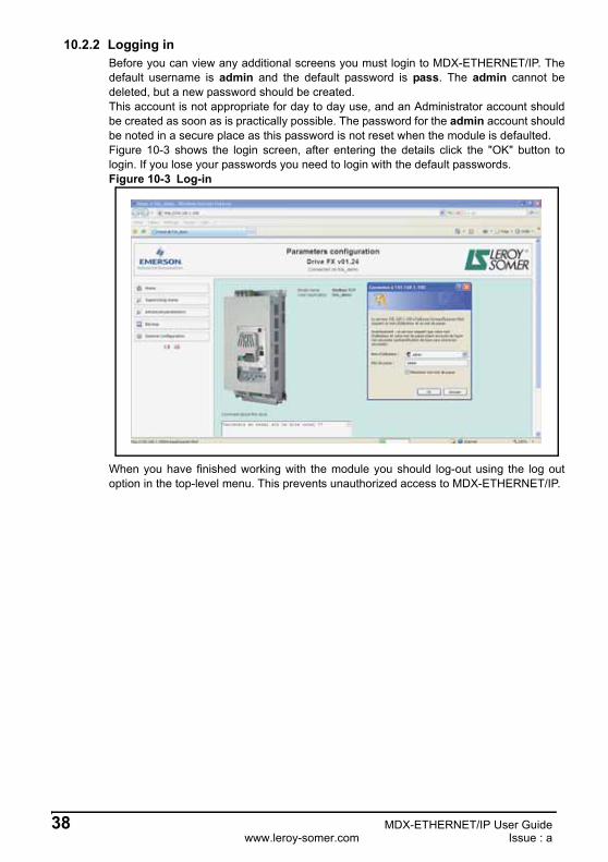
10.2.2 Logging inBefore you can view any additional screens you must login to MDX-ETHERNET/IP. Thedefault username is admin and the default password is pass. The admin cannot bedeleted, but a new password should be created.This account is not appropriate for day to day use, and an Administrator account shouldbe created as soon as is practically possible. The password for the admin account shouldbe noted in a secure place as this password is not reset when the module is defaulted.Figure 10-3 shows the login screen, after entering the details click the "OK" button tologin. If you lose your passwords you need to login with the default passwords. Figure 10-3 Log-in
When you have finished working with the module you should log-out using the log outoption in the top-level menu. This prevents unauthorized access to MDX-ETHERNET/IP.
MDX-ETHERNET/IP User Guide 39Issue : a www.leroy-somer.com
10.2.3 Advanced parametersDisplays a list of the menus within the host drive.Figure 10-4 Advanced parameters
10.2.4 BackupAllows data from the module to be uploaded for backup in module memory. This backuphas all module parameter values. This backup can be downloaded to any MDX-ETHERNET/IP module in the same network with its is Ethernet drive address.Figure 10-5 Send backup to another drive
Drive menu Read only parameter Read/Write parameter Switch parameter
Ethernet drive addressto send backup
Restore button
40 MDX-ETHERNET/IP User Guidewww.leroy-somer.com Issue : a
11 Security
11.1 IntroductionOn open networked systems it is important that security is considered. Security coversaspects such as access to devices using passwords, network infrastructure, companyprocedures and backup procedures.The physical system security should be enforced with acceptable user policies andappropriate employee guidelines.
11.2 General site security issues11.2.1 Connecting your computer
It is important to remember that when connecting your computer to an existing networkyou will have an impact on the data and services on that network. Particular care shouldbe taken not to interrupt the flow of data by disconnecting cables, powering downswitches/routers, or interrupting data flow by sending large amounts of data over thenetwork.
11.2.2 Virus considerationsConnecting your computer to a network carries the risk of transferring computer viruses toother computers on that network. It is vital that when connecting to a network you ensurethat your anti-virus software is up to date and activated. Many operating system vendorsoffer regular product updates to increase stability and reduce the risk of maliciousprograms causing damage to your corporate infrastructure.
11.2.3 Firewall issuesWhen a high level of security is required between the automation network and thebusiness network a firewall should be used. This helps prevent unwanted traffic passingbetween the networks and can be used to restrict access to certain machines or users.
11.3 Default restrictionsBy default, access to the drive over Ethernet is set to read/write access. By default, allservices are available. This can be changed using Pr 15.36 (please see section 13.4Disable full write access with acyclic for more information).
11.3.1 Disable Full AccessThe global write enable Pr 15.36 is set to 0 (disabled) by default. This will allowparameters to be changed within the drive. To prevent changes to drive parameters overEthernet web pages or ETHERNET/IP acyclic, Pr 15.36 should be set to a 1 (Enabled).
LEROY-SOMER recommend the use of a quality anti-virus solution on any networkedsystem. The overall network security policy resides with the network administrators andany connections to a network should be approved by the network administrators.
NOTE
Some managed switches provide control methods for network traffic, however a firewalloffers significantly more features. Configuration of a switch or firewall is beyond thescope of this document.
NOTE
MDX-ETHERNET/IP User Guide 41Issue : a www.leroy-somer.com
11.4 Account managementA user account system is provided to allow an administrator to give access rights todifferent classes of user. The system provides accounts for administrator and useraccount types. The default username admin and password pass should be used to gaininitial access to the module. Once logged on, additional accounts should be added asrequired, with key members of the engineering staff having supervisor access. It isrecommended that a policy is put into place to ensure that passwords are recordedelsewhere. There is a limit of one active user account.
11.5 Adding new accountsIn order to add a new account you will need to follow the instructions below:1. Log on to the web pages using the admin or an administrator account.2. Choose the top level General Configuration menu then the User setting menu.3. Enter the details as requested in the menu.4. Click "Create user" to finish.
11.5.1 Administrator accountsAdministrator accounts are intended to provide a high level of access to the drive andmodule settings. An administrator account should be reserved for engineering staff whohave a thorough understanding of the drive, MDX-ETHERNET/IP and the system.Where possible more than one person should be given administration privileges. Anadministrative account is required for adding/removing accounts.
11.5.2 Other user accountsOther user accounts should be used for engineers that need to make changes to thesystem occasionally, different account types are available depending on the facilitiesand features required. For more information see section 11.6 Security levels .
11.6 Security levelsSecurity levels are provided to allow different types of users to be given different accessrights to the drive and module parameters. Table 11.1 shows the access rights forspecific user types.
Table 11.1 Security levels
View HOME page
View supervising menu page
View advanced parameter pages
BackupView general
configuration page
Level 0 Yes Yes No No No
Level 1 Yes Yes Yes Yes No
Administrator Yes Yes Yes Yes Yes
42 MDX-ETHERNET/IP User Guidewww.leroy-somer.com Issue : a
12 Diagnostics
This section of the manual provides basic diagnostic information intended to enableresolution of the most common problems encountered when setting up a MDX-ETHERNET/IP module on an Ethernet network.A high percentage of problems reported are basic setup problems that can be avoided byusing the following pages. If after you are still experiencing problems please contact yoursupplier or local drive supplier for support.
12.1 LED diagnosticsThe MDX-ETHERNET/IP module is equipped with 2 LEDs on the front panel to aid in thediagnostics procedure. The functions of these LEDs are described in Table 12.1 LEDfunctionality below.Figure 12-1 LED functionality
Table 12.1 Network status LED (LED on the left)
Table 12.2 Module Status LED (LED on the right)
Table 12.3 LINK/Activity LED
Please note that support will be limited to the setting up and networking of the drive andnot network infrastructure design.
NOTE
# Item
1 Network status LED
2 Module status LED
3 Link/Activity Port 1
4 Link/Activity Port 2
A test sequence is performed on this LED during startup.
LED State Description
Off No power or no IP address
Green Online, one more connection established (CIP Class 1 or 3)
Green, flashing Online, no connection established
Red Duplicate IP address, or FATAL event
Red, flashing One or more connections timed out (CIP Class 1 or 3)
A test sequence is performed on this LED during startup.
LED State Description
Off No power
Green Controlled by a scanner in run state
Green, flashing Not configured, or scanner in Idle state
Red Major fault (EXCEPTION-state, FATAL error etc...)
Red, flashing Recoverable fault(s)
LED State Description
Off No link, no activity
Green Link established, 100 Mbit/s
Green, flickering Activity, 100 Mbit/s
Yellow Link established, 10 Mbit/s
Yellow, flickering Activity, 10 Mbit/s
NOTE
NOTE
MDX-ETHERNET/IP User Guide 43Issue : a www.leroy-somer.com
12.2 Module ID code
The module ID code indicates the type of module fitted in to the drive corresponding tomenu 15. The module ID code for MDX-ETHERNET/IP is 147.
12.3 Module firmware version
The software version of the option module can be identified by looking at Pr 15.02 andPr 15.51.The software version takes the form of xx.yy.zz, where Pr 15.02 displays xx.yy andPr 15.51 displays zz (e.g. for software version 01.01.00, Pr 15.02 will display 1.01 andPr 15.51 will display 0).
12.4 Node addressEach node on a MDX-ETHERNET/IP network must be given a unique network nodeaddress.The MDX-ETHERNET/IP must be re-initialised to make a change of node addressactive. See section 5.10 Setting the IP address or section 5.14 DHCP for moreinformation.
12.5 MDX-ETHERNET/IP baud rate
MDX-ETHERNET/IP can be set to automatically detect the baud rate or be fixed ateither 10Mbs or 100Mbs.
Table 12.4 MDX-ETHERNET/IP baud rate
Module ID code
Pr 15.01
Default 147
Range 0 to 499
Access RO
Firmware - major version (xx.yy)
Pr 15.02
Default N/A
Range 00.00 to 99.99
Access RO
Firmware - minor version (zz)
Pr 15.51
Default N/A
Range 0 to 99
Access RO
MDX-ETHERNET/IP baud rate
Pr 15.04
Default 0 (automatic)
Range 0 to 4
Access RW
Pr 15.04 (LCD display) Baud rate
0 (Automatic) Automatic detect
1 (10 MB half DX) 10 MB half Duplex
2 (10 MB full DX) 10 MB full Duplex
3 (100 MB half DX) 100 MB half Duplex
4 (100 MB full DX) 100 MB full Duplex
This parameter should normally be left in the auto detect state.NOTE
44 MDX-ETHERNET/IP User Guidewww.leroy-somer.com Issue : a
12.6 Data formatThe default data format is 2 cyclic channel OUT and IN, each cyclic data channel ismapped to a drive parameter. See section 7 cyclic data and 8 non cyclic data for moreinformation.
12.7 Fieldbus option state
The operating status of the MDX-ETHERNET/IP can be viewed in the fieldbus optionstate parameter (Pr 15.06). When the MDX-ETHERNET/IP is communicatingsuccessfully with the master controller, Pr 15.06 will give Master read.
Table 12.5 MDX-ETHERNET/IP operating status codes
If a mapping configuration error or network error is detected the drive may trip. Refer toSection 12.8 Cyclic parameter number (mapping status) for details about the trip display.
The maximum number of parameter data that is possible is 10 with only cyclic data.NOTE
Fieldbus option state
Pr 15.06
Default N/A
Range 0 to 14
Access RO
Pr 15.06 LCD display Description
0 Setup in progress MDX Setup in progress.
1 Network init
The module is currently performing network-related initialisation tasks. Telegrams now contains Process Data (if such data is mapped), however the network Process Data channel is not yet active.
2Network Process Data
inactiveThe network Process Data channel is temporarily inactive, wait cyclic.
3 IDLE
The network interface is idle. The exact interpretation of this state is network specific. Depending on the network type, the Read Process Data may be either updated or static (unchanged).
4 Process active The network Process Data channel is active and error free.
5 Bus error There is at least one serious network error.
6 Wait web updateWait a few minutes until Data base of new drive version is loaded in MDX option. Do not switch off the product during this period.
7 Host error
The module has ceased all network participation due to a host application-related error. This state is unrecoverable, i.e. the module must be restarted in order to be able to exchange network data.
8 Option bus loss Communication between MDX option and Drive is lost.
9 reserved
10 reserved
11 reserved
12 Host supervisingModule is supervised by another network device. Perform manual data handling.
13 reserved
14 reserved
MDX-ETHERNET/IP User Guide 45Issue : a www.leroy-somer.com
12.8 Cyclic mapping status
The MDX-ETHERNET/IP mapping status parameter Pr 15.49 indicates a mappingconfiguration error. When a mapping error has been corrected, re-initialise the MDX-ETHERNET/IP by setting Pr 15.32 to ON (1). The mapping error codes are described inTable 12.6.
Table 12.6 Mapping error codes
12.9 Drive trip display codesIf the MDX-ETHERNET/IP detects an error during operation, it will force a trip on thedrive. However, the trip code displayed on the drive will only indicate that MDX option isin fault. The exact reason for the trip will be indicated in the MDX-ETHERNET/IP errorcode parameter, Pr 15.50. Table 12.8 shows the possible trip codes that will bedisplayed on the drive when a problem is detected with the MDX-ETHERNET/IP orwhen the MDX-ETHERNET/IP initiates a trip.
12.10 Fieldbus trip
If the MDX-ETHERNET/IP detects an error during operation, it will force a trip on thedrive and update the error code parameter, Pr 15.50. Table 12.7 shows the possibleMDX-ETHERNET/IP error codes.
Table 12.7 MDX-ETHERNET/IP error codes
12.11 Module serial number
The serial number is loaded into the MDX-ETHERNET/IP during manufacture andcannot be changed. It contains the eight digit serial number located on the label.
Mapping status
Pr 15.49
Default N/A
Range 0 to 2
Access RO
Pr 15.49 LCD display Description
0 I/O good Mapping channels are good
1 Input bad IN Mapping channel is faulty (Pr 15.10 to Pr 15.19)
2 Out bad OUT Mapping channel is faulty (Pr 15.20 to Pr 15.29)
Fieldbus trip
Pr 15.50
Default N/A
Range 0 to 2
Access RO
Error code Fault display on LCD Description
0 No error codeIndicates that the MDX-ETHERNET/IP module is healthy. It is possible to trip the drive externally via various communication channels.
1 bus lossNo new messages have been received for the specified network loss trip time.
2 Option lossAn inter-option communications time-out has occurred, but the MDX-ETHERNET/IP is unable to determine the reason for the error.
Module serial number
Pr 15.35
Default N/A
Range 32 bit
Access RO
46 MDX-ETHERNET/IP User Guidewww.leroy-somer.com Issue : a
13 Advanced features
13.1 Data bytes order
When data is sent over the ETHERNET/IP network it is transmitted as 8-bit bytes.Therefore when a 32-bit word or 16-bit word is transmitted it is split into four or two 8-bitbytes. It is important that the receiving node reconstructs the received 8-bit bytes in thecorrect order to arrive at the 32-bit or 16-bit data value that was originally transmitted, thisorder is known as the Data Endian Format and is shown in Table 13.1.
Table 13.1 Data endian format
Most ETHERNET/IP master controllers use little endian format by default, many alsosupport big endian.
13.2 Compression of cyclical data
By default, the MDX-ETHERNET/IP uses 32-bits for each data channel, even if the targetparameter in the drive is a 16-bit, 8 bit or 1 bit parameter. This strategy (known as casting)ensures that the cyclic data transmitted over the ETHERNET/IP network is kept alignedwith memory locations in 32-bit PLCs. When cyclic data compression is enabled (Pr15.34 = ENABLED) a data channel will only use 32-bits if the target drive parameter is a32-bit parameter. If the target drive parameter is 16-bits wide 16-bits will be used. If thetarget drive parameter is only 1or 8 -bits wide 16-bits will be used for that particular datachannel. This is shown in Table 13.2.
Data bytes order
Pr 15.08
Default 0 (LSB first)
Range 0 to 1
Access RW
Data endian format
Pr 15.0816-bit value 32-bit value
Byte order Word order Byte order
Big1
(MSB first)High byte first
Low byte secondHigh word first
Low word second
High byte firstMid-high byte second
Mid-low byte thirdLow byte fourth
Little0
(LSB first)Low byte first
High byte secondLow word first
High word second
Low byte firstMid-low byte secondMid-high byte third
High byte fourth
Compression of cyclic data enable
Pr 15.34
Default 0 (disabled)
Range 0 to 1
Access RW
MDX-ETHERNET/IP User Guide 47Issue : a www.leroy-somer.com
Table 13.2 Actual data sizes
The following examples demonstrate setting up a network using five cyclic channels forboth IN and OUT data with the cyclic data compression first disabled and then enabled.
Table 13.3 shows the mapping parameters where five OUT and five IN cyclic datachannels are required. With data compression disabled each data channel uses 32-bits(two data words, so a total of ten words (20 bytes) are required, Pr 15.41 = 20,Pr 15.39 = 20).
Table 13.3 Example cyclic data channel mapping with compression disabled
It is advisable to keep 16-bit parameters paired together. This prevents mis-alignment ofcyclic data with 32-bit PLC registers when using auto-mapping facilities to configure theETHERNET/IP TCP network. By swapping the mappings for output channel 1 withoutput channel 2 and moving input channel 3 and 4 to input channel 1and 2, the datachannel structure will appear as shown in Table 13.4.
Table 13.4 Example cyclic data channel mapping with compression enabled
Parameter size (bits)Actual data size (bits)
compression enable (Pr 15.34)Actual data size (bits)
compression disabled (Pr 15.34)
1 16 32
8 16 32
16 16 32
32 32 32
Cyclic word Data word configuration on master Mapping
Out channel 0 2 OUT (Word 0,1) Pr 6.42, Control word
Out channel 1 2 OUT (Word 2,3) Pr 1.21, Digital speed reference 1
Out channel 2 2 OUT (Word 4,5) Pr 2.11, Ramp
Out channel 3 2 OUT (Word 6,7) Pr 4.07, Symetric Current Limit
Out channel 4 2 OUT (Word 8,9) Pr 4.10, Torque Offset Selection
In channel 0 2 IN (Word 0,1) Pr 10.40, Status word
In channel 1 2 IN (Word 2,3) Pr 2.01, Post ramp speed reference
In channel 2 2 IN (Word 4,5) Pr 4.02, Current
In channel 3 2 IN (Word 6,7) Pr 10.16, DC Bus undervoltage
In channel 4 2 IN (Word 8,9) Pr 10.17, Motor overload alarm
Cyclic wordData word configuration on
masterMapping
Out channel 0 1 OUT (Word 0) Pr 6.42, Control word
Out channel 1 1 OUT (Word 1) Pr 2.11, Ramp
Out channel 2 2 OUT (Word 2,3) Pr 1.21, Digital speed reference 1
Out channel 3 1 OUT (Word 4) Pr 4.07, Symmetrical Current Limit
Out channel 4 1 OUT (Word 5) Pr 4.10, Torque Offset Selection
In channel 0 1 IN ((Word 0) Pr 10.40, Status word
In channel 1 1 IN (Word 1) Pr 10.16, DC Bus undervoltage
In channel 2 2 IN (Word 2,3) Pr 4.02, Current
In channel 3 2 IN (Word 4,5) Pr 2.01, Post ramp speed reference
In channel 4 1 IN (Word 6) Pr 10.17, Motor overload alarm
48 MDX-ETHERNET/IP User Guidewww.leroy-somer.com Issue : a
13.3 Restore defaults
If the host drive is defaulted (see the drive user guide for details) it will also clear thecurrent configuration of the fitted MDX-ETHERNET/IP. Setting Pr 15.30 to 1 additionallyclears the backup copy of the stored MDX-ETHERNET/IP configuration.This can be performed as follows:
• Set Pr 15.30 to 1 (ENABLED).• ETHERNET/IP communications will be stopped.• The host drive will load and store its default parameter values.• Default parameter values for the MDX-ETHERNET/IP will be loaded.• The MDX-ETHERNET/IP will reset and re-initialise using the default values.
13.4 Disable full write access with acyclic or web page
This parameter will restrict a remote user's access to the drive. Pr 15.36 = read onlyensures that write access to the drive is disabled. Pr 15.36 = read write allows full accessto the drive parameters. With this parameter enabled, access with acyclic is not allowed.
13.5 E-mail configurationMDX-ETHERNET/IP provides the facilities for sending e-mail alerts. These e-mails areconfigured based on a trigger condition with Pr 15.53 or Pr 15.54.
13.5.1 RequirementsIn order to send e-mails you will need the following:
• A mail server that accepts SMTP connections and password if they have.• An e-mail address for MDX-ETHERNET/IP.• The IP address of the mail server.
13.5.2 SetupTo setup e-mail on MDX-ETHERNET/IP you must first be logged in with appropriatepermissions. From the General configuration menu then select E-mail settings option onthe menu. Enter the IP address and password of the mail server click on "store setting" tosave the settings.
Restore defaults
Pr 15.30
Default 0 (disabled)
Range 0 to 1
Access RW
Disable full write access
Pr 15.36
Default 0 (read write)
Range 0 to 1
Access RW
It is recommended that the address used is part of the standard corporate addressstructure (i.e. [email protected]), contact your system administrator foradvice on obtaining an e-mail address. MDX-ETHERNET/IP will not receive e-mail, andfacilities should be put in place to prevent mail going to this account residing on theserver.
NOTE
MDX-ETHERNET/IP User Guide 49Issue : a www.leroy-somer.com
13.5.3 E-mail triggersThe trigger requires a transition from 0 to 1 on Pr 15.53 or 15.54, after this transition e-mail is sent.
Pr 15.53 or 15.54 can be affected to a drive digital input.
To complete the process you need to enter an appropriate e-mail source name, adestination e-mail address, the title of the e-mail, any text you wish to send.
13.6 Network loss tripThe network loss trip provides a method on the drive to ensure that communication withthe master is still present. The MDX-ETHERNET/IP resets an internal timer when avalid message is received from the MDX-ETHERNET/IP network, if a message is notreceived within the specified period in ms, the network loss trip is triggered. If the trip isgenerated by MDX-ETHERNET/IP, the trip display on the drive will be "TR 34". TheMDX-ETHERNET/IP error code parameter (Pr 15.50) will show "Fieldbus loss" when anetwork loss trip has occurred.
Send e-mail on transition 0 -> 1
Pr 15.53Pr 15.54
Default 0 (OFF)
Range 0 (OFF) to 1 (ON)
Access RW
Network loss trip timeout
Pr 15.07
Default 1000
Range 0 to 10000
Access RW
The network loss trip can be disabled by setting Pr 15.07 to 0. In this case, the drive willcontinue to operate using the last received values. It is the user's responsibility toensure that adequate safety precautions are taken to prevent damage or injury bydisabling the drive in the event of a loss of communications.WARNING
50 MDX-ETHERNET/IP User Guidewww.leroy-somer.com Issue : a
14 Quick reference
14.1 Complete parameter referenceTable 14.1 lists all the MDX-ETHERNET/IP set-up parameters that are required toconfigure the module.
Table 14.1 MDX-ETHERNET/IP parameter reference
Parameter DefaultCross
referenceDescription
15.01 147 Page 43 plugged option ID code
15.02 ---- Page 43 Module software version (XX,YY)
15.34 0 (disabled) Page 46 Compression of cyclical data
15.35 --- Page 45 Serial number
15.36 0 (Read write) Page 48 Disable full write access
15.38 8 Page 29 Input cyclical data bytes
15.39 2 Page 27 IN cyclic, number of channel (parameter)
15.40 2 Page 27 OUT cyclic, number of channel (parameter)
15.41 8 Page 29 Output cyclical data bytes
15.49 --- Page 44 mapping status
15.50 0 (No error code) Page 45 Fieldbus trip
15.51 --- Page 43 Option minor firmware sub-version
MDX-ETHERNET/IP User Guide 51Issue : a www.leroy-somer.com
15.53 0 (disabled) Page 49 Send mail on transition 0 -> 1
15.54 0 (disabled) Page 49 Send mail on transition 0 -> 1
15.55 0 (no) Page 22 DHCP enable
15.60 192 Page 19 IP address Wip
15.61 168 Page 19 IP address Xip
15.62 1 Page 19 IP address Yip
15.63 100 Page 19 IP address Zip
15.64 255 Page 20 IP subnet mask Wsubnet
15.65 255 Page 20 IP subnet mask Xsubnet
15.66 255 Page 20 IP subnet mask Ysubnet
15.67 0 Page 20 IP subnet mask Zsubnet
15.68 192 Page 21 IP default gateway Wgateway
15.69 168 Page 21 IP default gateway Xgateway
15.70 1 Page 21 IP default gateway Ygateway
15.71 254 Page 21 IP default gateway Zgateway
Parameter DefaultCross
referenceDescription
52 MDX-ETHERNET/IP User Guidewww.leroy-somer.com Issue : a
15 Glossary of termsAddress: This is the unique network identification given to a networked device to allowcommunication on a network. When a device sends or receives data the address is usedto determine the source and the destination of the message.
Auto-crossover detection: A method used to automatically detect if a crossover or non-crossover network cable is connected.
Bit: A binary digit, this may have the value of 1 or 0.
Byte: A collection of 8 binary digits that collectively store a value. This may be signed orunsigned.
Casting: The process of changing between data sizes without changing the valuerepresented, e.g. changing from 16-bit to 32-bit.
Compression: By default MDX-ETHERNET/IP transmits values as 32-bits on thenetwork. It is possible by using data compression to reduce the number of bits transmittedwhen sending 16-bit (or smaller) values on the network to 16-bit (32-bit values will still betransmitted as 32-bit values). This has the advantage of reducing the volume of traffic onthe network.
Control word: A collection of binary digits that are used to control the drive. Featurestypically include directional controls, run controls and other similar functions.
Data rate: Determines the communication speed of the network, the higher the value themore data can be sent across the network in the same time period.
Device: A piece of equipment connected to a network, this may be any type of equipmentincluding repeaters, hubs, masters or slaves.
DNS: Domain Name Server. This is a server that is used to convert a URL such as"www.leroy-somer.com" to an IP address such as 129.254.254.106.
Double word: A 32 bit word, this may be signed or unsigned.
DHCP: Dynamic Host Configuration Protocol. This is a method of allocating IP settings ofa node from a central server.
EDS File: Electronic Data Sheet file. A file which specifies the Ethernet/IP devicefunctionality.
Ethernet address: See MAC address.
Ethernet/IP: An industrial application layer protocol for communicating to devices overEthernet. The Ethernet/IP protocol communicates to the drive using assembly objects.
Explicit data: See Non-cyclic data.
MDX-ETHERNET/IP User Guide 53Issue : a www.leroy-somer.com
Firewall: A computer or piece of software that restricts connections between differentports. This can be useful when restricting data flow between two network segments.
FTP: File Transfer Protocol. Used for transferring files.
Gateway: A device that allows devices on different subnets or networks tocommunicate with each other.
Grounding: Describes the electrical safety or shielding connections for the module.
Hub: A method of connecting computers together on Ethernet. An un-switched hub willrepeat any data received on one port to all ports.
HTTP: Hypertext transfer protocol. This is a document specification protocol. Commonlyused in web pages.
Implicit data: See Cyclic data.
IN data: Data that is returned from a slave device to the ethernet master.
IP: Internet Protocol, this is the protocol used to transmit bytes across an IP network.
IP address: An address that identifies a node uniquely on a subnet or network.
IP subnet: A part of an IP network that consists of a range of addresses that may beaccessed by all devices on the same network directly.
LED: Light Emitting Diode.
Long word: A 32 bit data word that may be signed or unsigned.
LSB: Least Significant Bit/Byte.
Master: The controlling device on the network, generally this will include programmingfeatures.
MAC address: This is a unique address that is assigned to MDX-ETHERNET/IP at thetime of manufacture. No other device will have this address. The address is used tomake connections to the module before the IP address is assigned.
MSB: Most Significant Bit/Byte.
Network Loss Trip: A way to determine when a node has lost contact with the master.
Node: A device on the network. This may be either a device such as a drive or part ofthe network such as a repeater.
Non-Cyclic Data: Data that is requested or sent by the master as required. This is notsent on a regular basis and generally allows access to any parameter. This is useful foroccasional changes or configuration purposes.
Octet: A collection of 8 binary digits which form a byte.
54 MDX-ETHERNET/IP User Guidewww.leroy-somer.com Issue : a
Patch lead: A network cable where the terminal connections at one end of the cable areconnected straight through to the other end on a pin to pin basis. Normally used toconnect a network device to a network switch.
PC: Personal Computer.
PLC: Programming Logic Controller.
Polled data: See Cyclic data.
RPI: Requested Packet Interval. Specifies the expected time for the device to respond toa request.
Router: A device that is used to connect different networks or subnets, in a similar way toa firewall, however a router generally allows significantly less control of the data.
Shielding: A connection to provide additional immunity to noise used on a network cable.
SMTP: Simple Mail Transfer Protocol. A protocol used for sending e-mail.
SNTP: Simple Network Time Protocol. A protocol used for synchronizing time over anetwork.
Status word: A value that denotes the status of the drive. Each bit within the word willhave a specific meaning.
Subnet: A part of a network that has IP addresses in the same range. Devices on thesame subnet may communicate directly with other devices on the same subnet withoutthe use of a gateway.
Subnet mask: Defines which part of the IP address constitutes the subnet address andwhich part constitutes the host device address.
Switch: A device that allows Ethernet devices to be interconnected.
TCP: Transmission Control Protocol, this protocol is responsible for ensuring that thedata on the network reaches it's destination.
URL: Uniform Resource Locator. A method used to give a web site a friendly name suchas www.leroy-somer.com as an alternative to an IP address.
VPN: Virtual Private Network. A method of using a non-secure or public network thatallows devices to be connected together as if they were a part of a private network.
Word: A collection of 16 binary digits.
MDX-ETHERNET/IP User Guide 55Issue : a www.leroy-somer.com
Note
56 MDX-ETHERNET/IP User Guidewww.leroy-somer.com Issue : a
Note
MDX-ETHERNET/IP User Guide 57Issue : a www.leroy-somer.com
Note
58 MDX-ETHERNET/IP User Guidewww.leroy-somer.com Issue : a
Note
MOTEURS LEROY-SOMER 16915 ANGOULÊME CEDEX 9 - FRANCE
338 567 258 RCS ANGOULÊMESimplified Joint Stock Company with capital of 65,800,512 €