ME 305 Fluid Mechanics I Part 2 Fluid Statics These presentations are prepared by Dr. Cüneyt Sert Mechanical Engineering Department Middle East Technical University Ankara, Turkey [email protected]Please ask for permission before using them. You are NOT allowed to modify them. 2-1
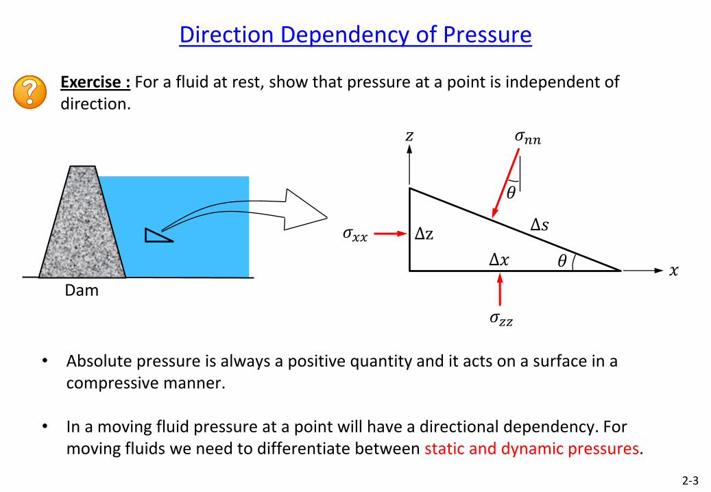
Exercise : For a fluid at rest, show that pressure at a point is independent of direction.
∆𝑥
∆z ∆𝑠
𝜍𝑛𝑛
𝜍𝑥𝑥
𝜍𝑧𝑧
𝑥
𝑧
𝜃
𝜃
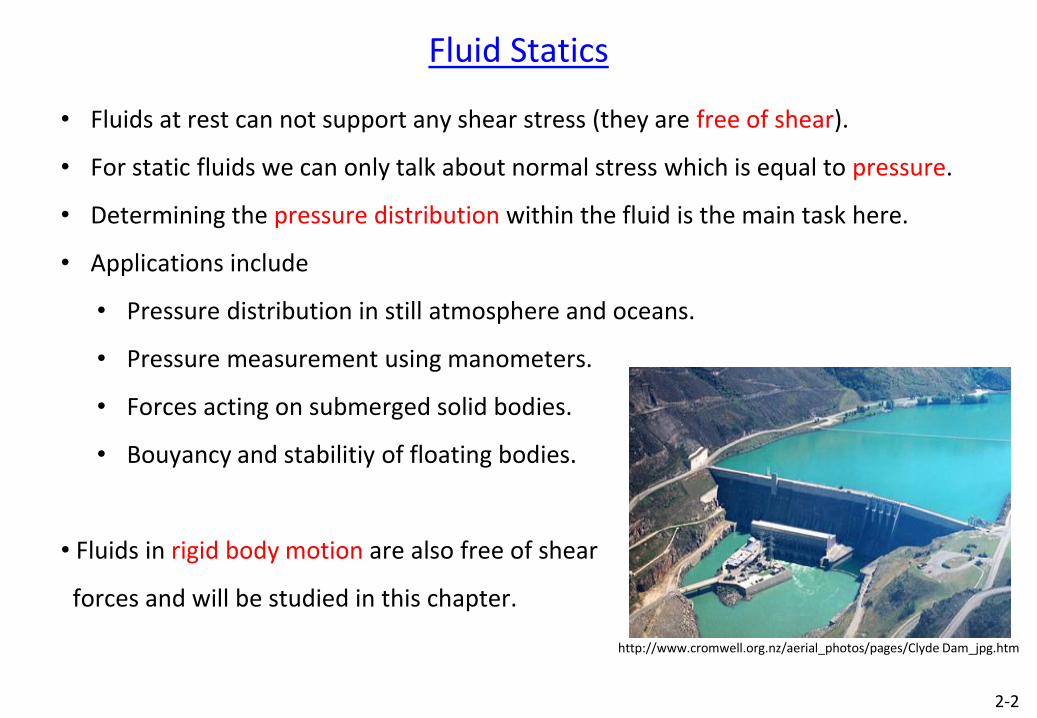
• Absolute pressure is always a positive quantity and it acts on a surface in a compressive manner.
• In a moving fluid pressure at a point will have a directional dependency. For moving fluids we need to differentiate between static and dynamic pressures.
2-3
Dam
Pressure Variation in a Static Fluid
• As we dive deep into the sea we feel more pressure in our ears.
• When we travel to high altitudes atmospheric pressure decreases.
• Following fluid element in a static fluid is not moving because no net force acts on it.
• Body force acting on the fluid element should be balanced by another force.
• This other force is due to the pressure difference within the fluid.
Exercise : Show that in a static fluid −𝛻𝑝 + 𝜌𝑔 = 0
dx dy
dz
2-4
Pressure Variation in a Static Fluid
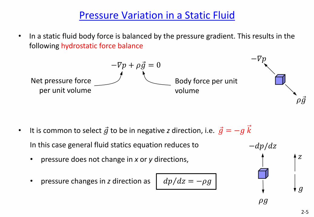
• In a static fluid body force is balanced by the pressure gradient. This results in the following hydrostatic force balance
−𝛻𝑝 + 𝜌𝑔 = 0
• It is common to select 𝑔 to be in negative z direction, i.e. 𝑔 = −𝑔 𝑘
In this case general fluid statics equation reduces to
• pressure does not change in x or y directions,
• pressure changes in z direction as 𝑑𝑝 𝑑𝑧 = −𝜌𝑔
Body force per unit volume
Net pressure force per unit volume
𝜌𝑔
−𝛻𝑝
𝜌𝑔
−𝑑𝑝/𝑑𝑧
𝑧
𝑔
2-5
Pressure in an Incompressible Static Fluid (cont’d)
• Question : How do 𝜌 and 𝑔 change with 𝑧 ?
• Answer : It is safe to consider 𝑔 to be constant. At sea level it is 9.807 m/s2 and at
14 km altitude it is 9.764 m/s2. Also for simplicity let’s consider constant density first.
• If 𝜌𝑔 is constant 𝑑𝑝 𝑑𝑧 = −𝜌𝑔 can be integrated to give
𝑝 + 𝜌𝑔𝑧 = constant
𝑝1 + 𝜌𝑔𝑧1 = 𝑝2 + 𝜌𝑔𝑧2
𝑝2 = 𝑝1 + 𝜌𝑔(𝑧1−𝑧2)
𝑝2 = 𝑝1 + 𝜌𝑔ℎ 𝑧
𝑔
𝑝1
ℎ 𝑧1
𝑧2
𝑝2
• As we go down in a constant density fluid pressure increases with depth as 𝜌𝑔ℎ. 2-6
Pressure in an Incompressible Static Fluid (cont’d)
Exercise : How deep in a pool should you dive to feel twice the atmospheric pressure ?
In 1960 Trieste sea vessel carried two oceanographers to the deepest point in Earth’s oceans, Challenger Deep in the Mariana Trench (10,916 m). What is the pressure there? Can we consider water density to be constant ?
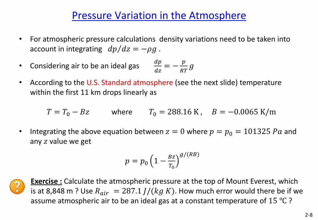
• For atmospheric pressure calculations density variations need to be taken into account in integrating 𝑑𝑝 𝑑𝑧 = −𝜌𝑔 .
• Considering air to be an ideal gas 𝑑𝑝
𝑑𝑧= −
𝑝
𝑅𝑇𝑔
• According to the U.S. Standard atmosphere (see the next slide) temperature within the first 11 km drops linearly as
𝑇 = 𝑇0 − 𝐵𝑧 where 𝑇0 = 288.16 K , 𝐵 = −0.0065 K/m
• Integrating the above equation between 𝑧 = 0 where 𝑝 = 𝑝0 = 101325 𝑃𝑎 and any 𝑧 value we get
𝑝 = 𝑝0 1 −𝐵𝑧
𝑇0
𝑔/(𝑅𝐵)
Exercise : Calculate the atmospheric pressure at the top of Mount Everest, which is at 8,848 m ? Use 𝑅𝑎𝑖𝑟 = 287.1 𝐽/(𝑘𝑔 𝐾). How much error would there be if we assume atmospheric air to be an ideal gas at a constant temperature of 15 ℃ ?
2-8
-60 -40 -20 0 15
Temperature [oC]
Alt
itu
de
z
[km
]
60
50
40
30
20
10
-56
.5 20.1 km
11 km
Tro
po
sph
ere
0 0 40 80 120
Pressure [kPa]
Alt
itu
de
z
[km
]
60
50
40
30
20
10
0
U.S. Standard Atmosphere
2-9
Pressure Variation in the Atmosphere (cont’d)
• At sea level and 15 oC, atmospheric pressure is 101,325 Pa = 1 atm
• This value changes with elevation, however we assume it to be constant in laboratory scales, where the elevation difference is just a couple of meters.
• At high altitudes air is less dense and we get less oxygen in one breathing. Therefore we get tired more easily.
• Also an automobile engine gets less air (in terms of mass) into its cylinders and performs poorly at high altitudes.
2-10
Absolute vs Gage Pressure
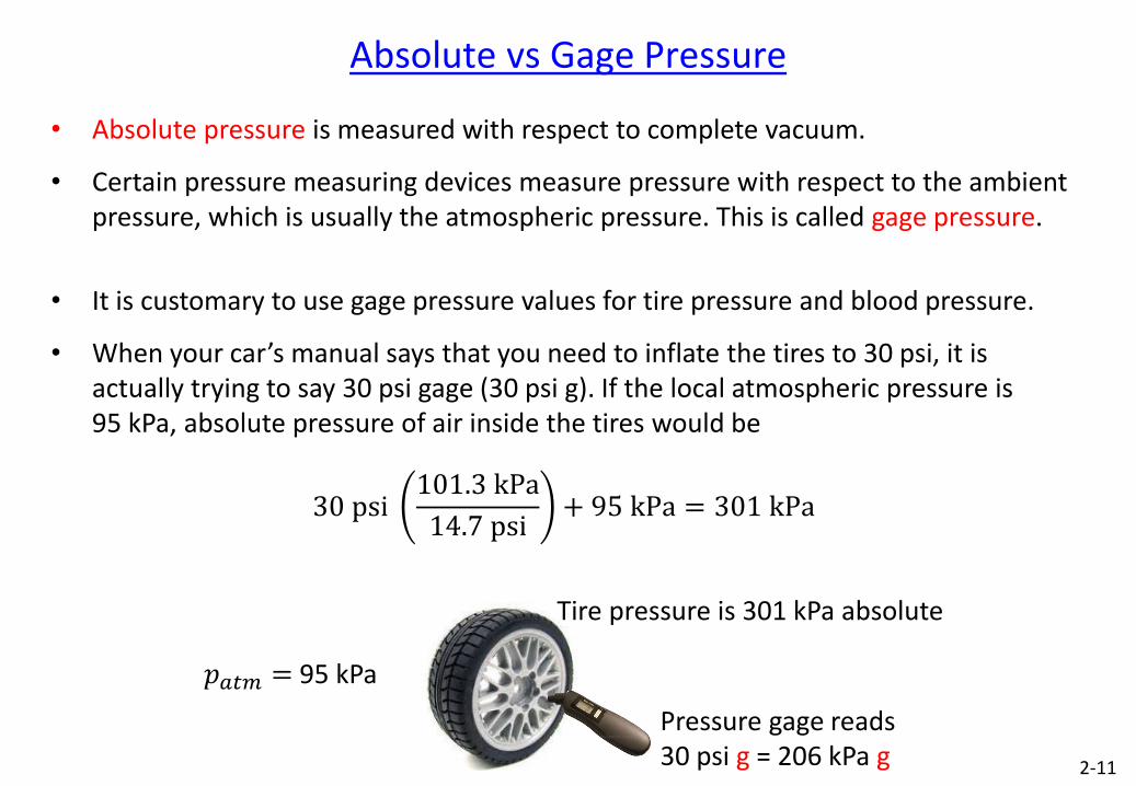
• Absolute pressure is measured with respect to complete vacuum.
• Certain pressure measuring devices measure pressure with respect to the ambient pressure, which is usually the atmospheric pressure. This is called gage pressure.
• It is customary to use gage pressure values for tire pressure and blood pressure.
• When your car’s manual says that you need to inflate the tires to 30 psi, it is actually trying to say 30 psi gage (30 psi g). If the local atmospheric pressure is 95 kPa, absolute pressure of air inside the tires would be
30 psi 101.3 kPa
14.7 psi+ 95 kPa = 301 kPa
Pressure gage reads 30 psi g = 206 kPa g
𝑝𝑎𝑡𝑚 = 95 kPa
Tire pressure is 301 kPa absolute
2-11
Mercury Barometer
• In 1643 Toricelli demonstrated that atmospheric pressure can be measured using a mercury barometer. Greek word “baros” means weight.
𝑝𝐵 = 𝑝𝑚𝑒𝑟𝑐𝑢𝑟𝑦 𝑣𝑎𝑝𝑜𝑟 ≈ 0
𝑝𝐴 = 𝑝𝑎𝑡𝑚
𝑝𝐴 = 𝑝𝐵 + 𝜌𝑚𝑔ℎ
𝑝𝑎𝑡𝑚 = 𝜌𝑚𝑔ℎ
• For 𝑝𝑎𝑡𝑚 = 101,325 Pa and 𝜌𝑚= 13,595 kg/m3 mercury rise will be ℎ = 0.76 m.
• mmHg is a unit used for pressure. It gives the pressure difference between the top and bottom of a 1 mm mercury column
1 mmHg = 13595kg
m39.81
m
s210−3 m = 133.4 Pa
1 atm = 101,325 Pa = 760 mmHg
h
𝜌𝑚 A
B 𝑝𝑎𝑡𝑚 = ?
2-12
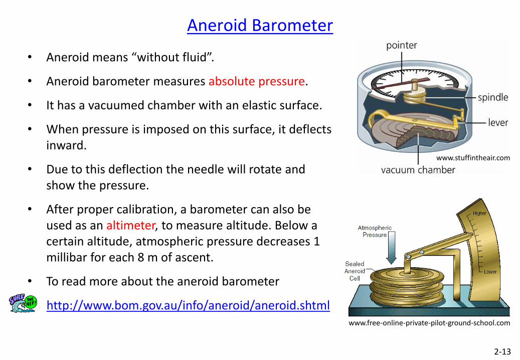
• Aneroid means “without fluid”.
• Aneroid barometer measures absolute pressure.
• It has a vacuumed chamber with an elastic surface.
• When pressure is imposed on this surface, it deflects inward.
• Due to this deflection the needle will rotate and show the pressure.
• After proper calibration, a barometer can also be used as an altimeter, to measure altitude. Below a certain altitude, atmospheric pressure decreases 1 millibar for each 8 m of ascent.
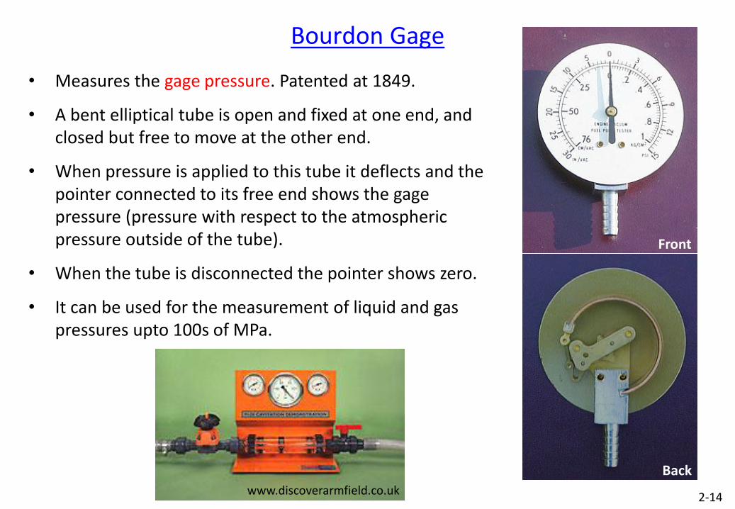
• A bent elliptical tube is open and fixed at one end, and closed but free to move at the other end.
• When pressure is applied to this tube it deflects and the pointer connected to its free end shows the gage pressure (pressure with respect to the atmospheric pressure outside of the tube).
• When the tube is disconnected the pointer shows zero.
• It can be used for the measurement of liquid and gas pressures upto 100s of MPa.
Bourdon Gage
www.discoverarmfield.co.uk
Front
Back
2-14
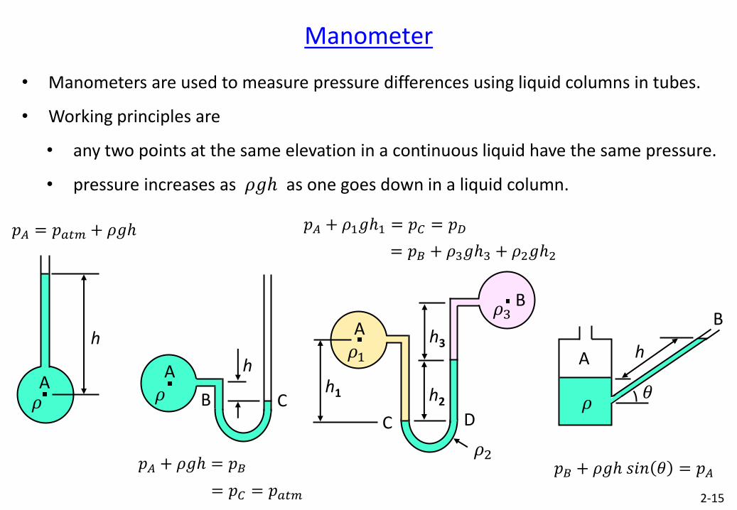
• Manometers are used to measure pressure differences using liquid columns in tubes.
• Working principles are
• any two points at the same elevation in a continuous liquid have the same pressure.
• pressure increases as 𝜌𝑔ℎ as one goes down in a liquid column.
A
h
𝜌
𝑝𝐴 = 𝑝𝑎𝑡𝑚 + 𝜌𝑔ℎ
𝑝𝐵 + 𝜌𝑔ℎ 𝑠𝑖𝑛 𝜃 = 𝑝𝐴
A
B
𝜃
h
𝜌
Manometer
A 𝜌
h
B C
𝑝𝐴 + 𝜌𝑔ℎ = 𝑝𝐵
= 𝑝𝐶 = 𝑝𝑎𝑡𝑚
A 𝜌1
h2
C D
B 𝜌3
𝜌2
h1
h3
𝑝𝐴 + 𝜌1𝑔ℎ1 = 𝑝𝐶 = 𝑝𝐷
= 𝑝𝐵 + 𝜌3𝑔ℎ3 + 𝜌2𝑔ℎ2
2-15
Hydrostatic Forces Acting on Submerged Surfaces
• Pressure always acts perpendicular to a surface.
Exercise : Show the variation of pressure force acting on the walls of the following containers.
• The task is to find the resultant pressure force acting on a submerged surface and point of application of the resultant pressure force.
• Different techniques can be used such as
• Direct Integration Method
• Formula Method 2-16
• Pressure Prism Method
• Force Component Method
𝑝𝑎𝑡𝑚 𝑝𝑎𝑡𝑚
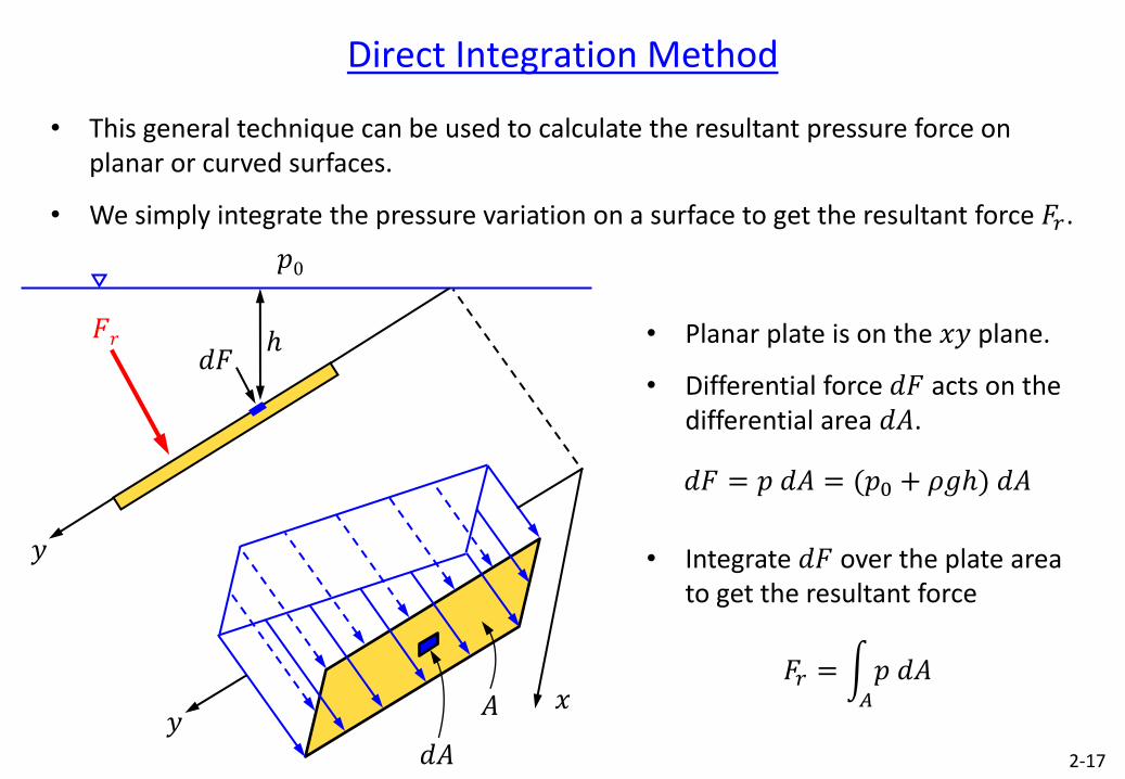
Direct Integration Method
• This general technique can be used to calculate the resultant pressure force on planar or curved surfaces.
• We simply integrate the pressure variation on a surface to get the resultant force 𝐹𝑟.
2-17
𝑦
𝑑𝐹 𝐹𝑟
𝑝0
ℎ
𝑦 𝑥
𝑑𝐴
𝐴
• Planar plate is on the 𝑥𝑦 plane.
• Differential force 𝑑𝐹 acts on the differential area 𝑑𝐴.
𝑑𝐹 = 𝑝 𝑑𝐴 = (𝑝0 + 𝜌𝑔ℎ) 𝑑𝐴
• Integrate 𝑑𝐹 over the plate area to get the resultant force
𝐹𝑟 = 𝑝 𝑑𝐴
𝐴
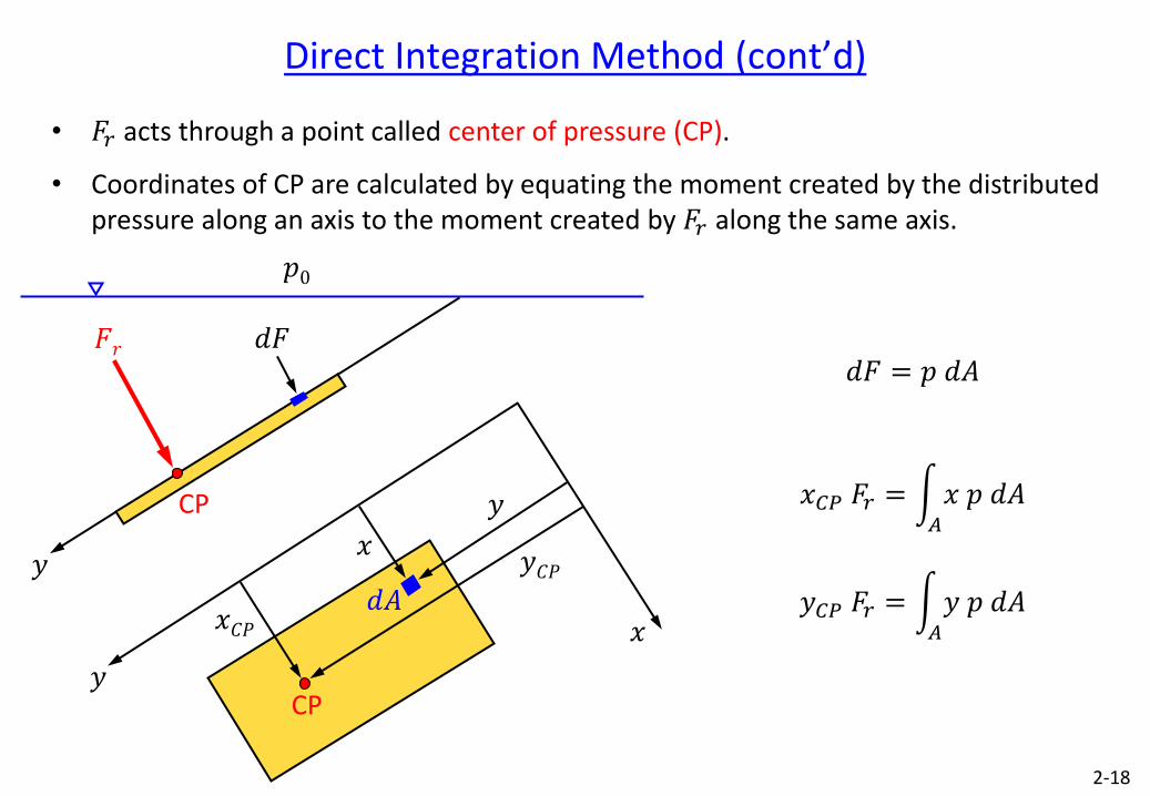
Direct Integration Method (cont’d)
• 𝐹𝑟 acts through a point called center of pressure (CP).
• Coordinates of CP are calculated by equating the moment created by the distributed pressure along an axis to the moment created by 𝐹𝑟 along the same axis.
2-18
𝑦
𝑑𝐹 𝐹𝑟
𝑝0
𝑦
𝑥 𝑑𝐴
CP
𝑥𝐶𝑃
𝑦
𝑥
CP
𝑦𝐶𝑃
𝑑𝐹 = 𝑝 𝑑𝐴
𝑥𝐶𝑃 𝐹𝑟 = 𝑥 𝑝 𝑑𝐴
𝐴
𝑦𝐶𝑃 𝐹𝑟 = 𝑦 𝑝 𝑑𝐴
𝐴
Exercise : Solve the previous problem by considering a triangular gate as shown below.
Direct Integration Method (cont’d)
Exercise : Rectangular gate of size 6 m × 3 m is hinged along B and held by horizontal force 𝐹𝐴 applied at A. The liquid on the left of the gate is water. Calculate the force 𝐹𝐴 required for equilibrium.
2-19
𝐹𝐴 A
B
3 m
6 m
Exercise : Solve the previous problem by considering a semicircular gate as shown below.
𝐹𝐴 A
B
3 m
6 m
𝐹𝐴 A
B
8 m
3 m Side view
of gate
6 m
Formula Method
Exercise : Show that for a submerged planar surface resultant pressure force is equal to the pressure at the geometric center of the surface multiplied by the surface area.
𝑦
𝑥 𝑑𝐴
CP
𝑥𝐶𝑃
𝑦𝐶𝑃 𝑥𝐺
𝑦𝐺
G
𝑦
𝑥 𝑦
𝑧 ℎ 𝑑𝐹
𝛽
𝐹𝑟
ℎ𝐶𝑃
CP G
ℎ𝐺
𝑝0
2-20
𝐹𝑟 = 𝑝𝐺𝐴 Note that in general points G and CP are not the same.
Exercise : Think about a case for which points G and CP are the same?
Examples for Submerged Planar Surfaces
Exercise : A 2 m wide planar gate of uniform thickness holds back a depth of water as shown. It is hinged along its top side. Find the minimum gate weight needed to keep the gate closed. You can use either direct integration or formula method.
2-21
Exercise : As water rises on the left side of the rectangular gate, the gate will open automatically. At what depth 𝐷 above the hinge will this occur ? How will the result change if the mass of the gate is considered ? You can use either direct integration or formula method.
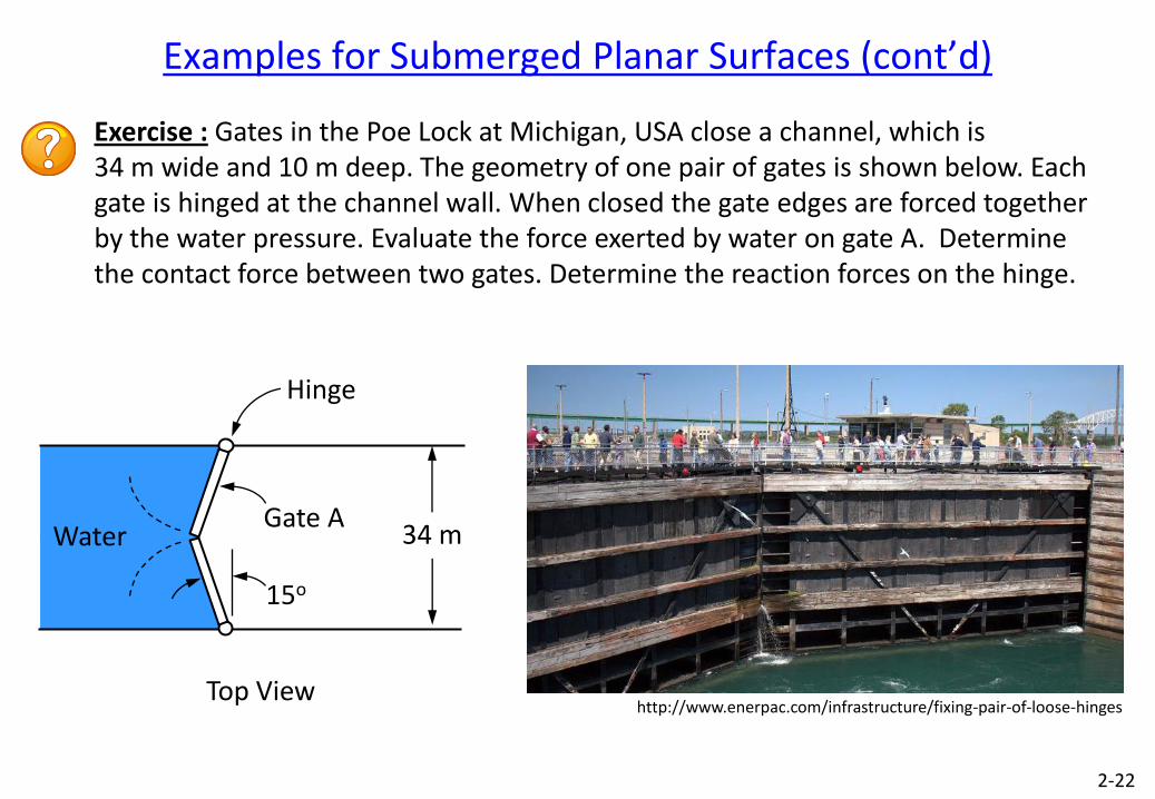
Exercise : Gates in the Poe Lock at Michigan, USA close a channel, which is 34 m wide and 10 m deep. The geometry of one pair of gates is shown below. Each gate is hinged at the channel wall. When closed the gate edges are forced together by the water pressure. Evaluate the force exerted by water on gate A. Determine the contact force between two gates. Determine the reaction forces on the hinge.
Examples for Submerged Planar Surfaces (cont’d)
Hinge
Gate A 34 m Water
15o
Top View
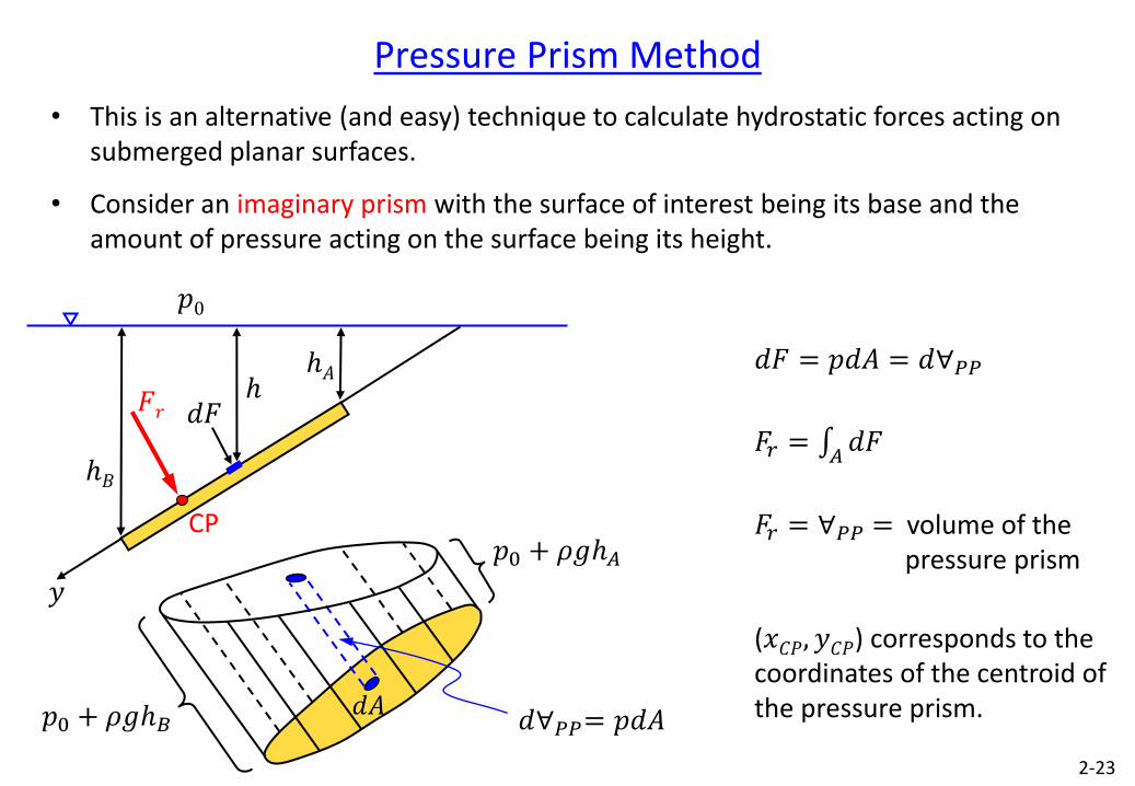
Pressure Prism Method
• This is an alternative (and easy) technique to calculate hydrostatic forces acting on submerged planar surfaces.
• Consider an imaginary prism with the surface of interest being its base and the amount of pressure acting on the surface being its height.
2-23
𝑑𝐹 = 𝑝𝑑𝐴 = 𝑑∀𝑃𝑃
𝐹𝑟 = 𝑑𝐹
𝐴
𝐹𝑟 = ∀𝑃𝑃 = volume of the pressure prism
(𝑥𝐶𝑃, 𝑦𝐶𝑃) corresponds to the coordinates of the centroid of the pressure prism.
𝑦
ℎ𝐴
𝑑𝐹 𝐹𝑟
CP
𝑝0
ℎ𝐵
ℎ
𝑝0 + 𝜌𝑔ℎ𝐴
𝑝0 + 𝜌𝑔ℎ𝐵 𝑑𝐴 𝑑∀𝑃𝑃= 𝑝𝑑𝐴
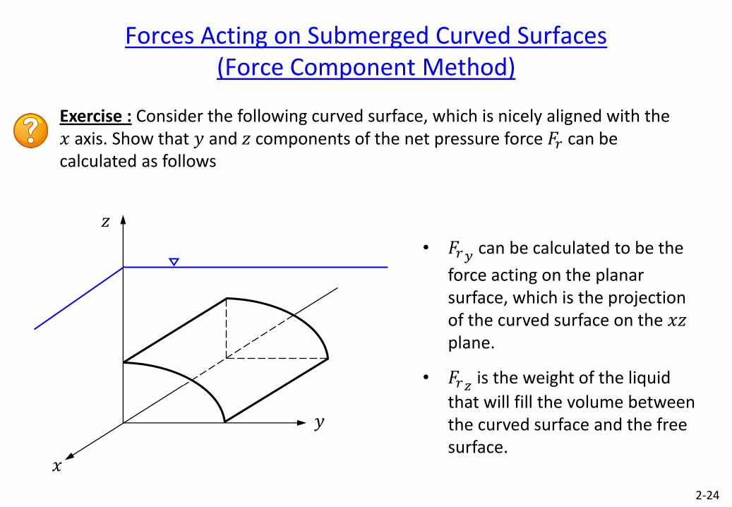
Forces Acting on Submerged Curved Surfaces (Force Component Method)
Exercise : Consider the following curved surface, which is nicely aligned with the 𝑥 axis. Show that 𝑦 and 𝑧 components of the net pressure force 𝐹𝑟 can be calculated as follows
2-24
𝑧
𝑥
𝑦
• 𝐹𝑟𝑦 can be calculated to be the
force acting on the planar surface, which is the projection of the curved surface on the 𝑥𝑧 plane.
• 𝐹𝑟𝑧 is the weight of the liquid
that will fill the volume between the curved surface and the free surface.
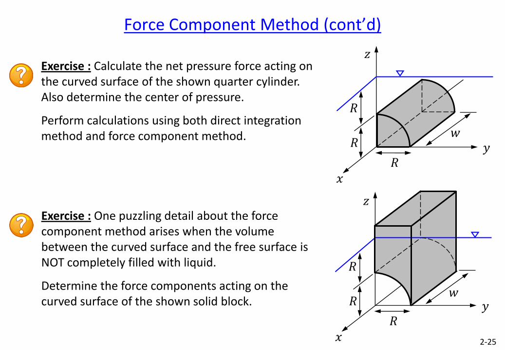
Force Component Method (cont’d)
Exercise : Calculate the net pressure force acting on the curved surface of the shown quarter cylinder. Also determine the center of pressure.
Perform calculations using both direct integration method and force component method.
2-25
Exercise : One puzzling detail about the force component method arises when the volume between the curved surface and the free surface is NOT completely filled with liquid.
Determine the force components acting on the curved surface of the shown solid block.
𝑧
𝑥
𝑦 𝑅
𝑅
𝑅
𝑤
𝑧
𝑥
𝑦 𝑅
𝑅
𝑅
𝑤
2-26
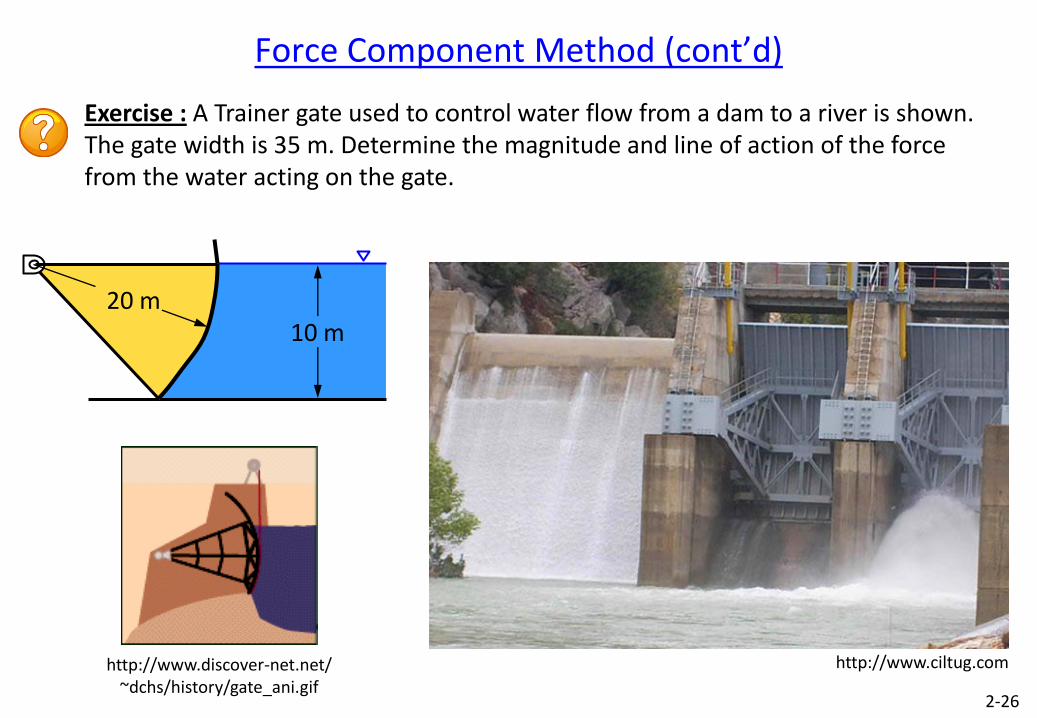
Exercise : A Trainer gate used to control water flow from a dam to a river is shown. The gate width is 35 m. Determine the magnitude and line of action of the force from the water acting on the gate.
• Consider a body that is fully submerged (could be floating also) in a static fluid.
• A distributed pressure force acts all around the body.
• Using the Force Component Method we can show that the net horizontal pressure force acting on the body is zero.
• Net vertical pressure force is however is not zero. It is called the buoyancy force.
2-27
Buoyancy Force
3D body
Left and right parts have the same vertical projetion.
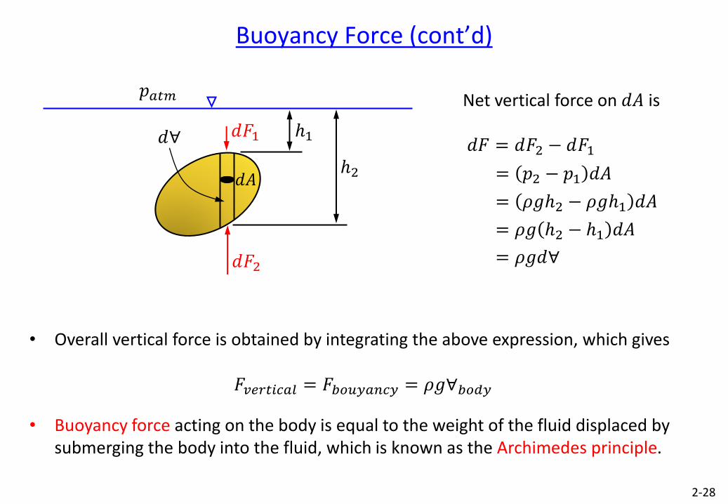
• Overall vertical force is obtained by integrating the above expression, which gives
𝐹𝑣𝑒𝑟𝑡𝑖𝑐𝑎𝑙 = 𝐹𝑏𝑜𝑢𝑦𝑎𝑛𝑐𝑦 = 𝜌𝑔∀𝑏𝑜𝑑𝑦
• Buoyancy force acting on the body is equal to the weight of the fluid displaced by submerging the body into the fluid, which is known as the Archimedes principle.
2-28
Buoyancy Force (cont’d)
𝑑𝐹2
𝑑∀
𝑝𝑎𝑡𝑚
𝑑𝐴
𝑑𝐹1 ℎ1
ℎ2
Net vertical force on 𝑑𝐴 is
𝑑𝐹 = 𝑑𝐹2 − 𝑑𝐹1
= 𝑝2 − 𝑝1 𝑑𝐴
= 𝜌𝑔ℎ2 − 𝜌𝑔ℎ1 𝑑𝐴
= 𝜌𝑔 ℎ2 − ℎ1 𝑑𝐴
= 𝜌𝑔𝑑∀
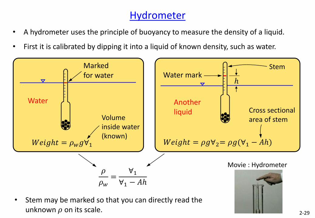
• A hydrometer uses the principle of buoyancy to measure the density of a liquid.
• First it is calibrated by dipping it into a liquid of known density, such as water.
2-29
Hydrometer
𝑊𝑒𝑖𝑔ℎ𝑡 = 𝜌𝑤𝑔∀1 𝑊𝑒𝑖𝑔ℎ𝑡 = 𝜌𝑔∀2= 𝜌𝑔(∀1 − 𝐴ℎ)
𝜌
𝜌𝑤=
∀1∀1 − 𝐴ℎ
• Stem may be marked so that you can directly read the unknown 𝜌 on its scale.
Movie : Hydrometer
Volume inside water (known)
Water
Marked for water
Cross sectional area of stem
Water mark
Another liquid
ℎ
Stem
Glass tube
water mercury
2-30
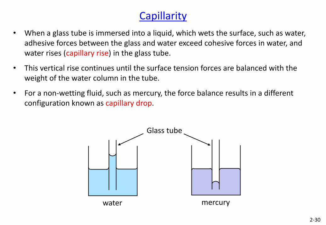
• When a glass tube is immersed into a liquid, which wets the surface, such as water, adhesive forces between the glass and water exceed cohesive forces in water, and water rises (capillary rise) in the glass tube.
• This vertical rise continues until the surface tension forces are balanced with the weight of the water column in the tube.
• For a non-wetting fluid, such as mercury, the force balance results in a different configuration known as capillary drop.
Capillarity
2-31
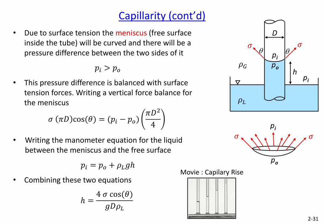
• Due to surface tension the meniscus (free surface inside the tube) will be curved and there will be a pressure difference between the two sides of it
𝑝𝑖 > 𝑝𝑜
• This pressure difference is balanced with surface tension forces. Writing a vertical force balance for the meniscus
𝜍 𝜋𝐷 cos (𝜃) = (𝑝𝑖 − 𝑝𝑜)𝜋𝐷2
4
• Writing the manometer equation for the liquid between the meniscus and the free surface
𝑝𝑖 = 𝑝𝑜 + 𝜌𝐿𝑔ℎ
• Combining these two equations
ℎ =4 𝜍 cos (𝜃)
𝑔𝐷𝜌𝐿
Capillarity (cont’d)
𝜍 q q
D
po h
𝜌𝐺
𝜌𝐿
pi
pi
𝜍
𝜍 𝜍
po
pi
Movie : Capilary Rise
2-32
• Consider a body of fluid that is in rigid body motion, i.e. fluid moves as if it is a solid body and fluid partciles have no relative motion with respect to each other.
• In such a case fluid is free of shear stress.
• Two examples of this are fluids moving with constant linear acceleration and fluids rotating around an axis of rotation with constant angular velocity.
Fluids in Rigid Body Motion
Liquid
Stationary liquid with a horizontal
free surface
Liquid
Linear acceleration causes a tilted planar free surface. a
Liquid
𝜔
Rotation (centripetal acceleration) causes a curved (parabolic) free surface.
2-33
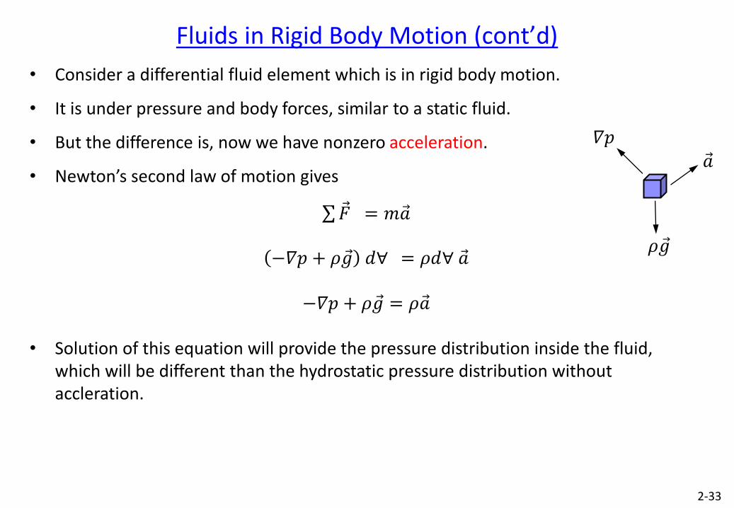
• Consider a differential fluid element which is in rigid body motion.
• It is under pressure and body forces, similar to a static fluid.
• But the difference is, now we have nonzero acceleration.
• Newton’s second law of motion gives
𝐹 = 𝑚𝑎
−𝛻𝑝 + 𝜌𝑔 𝑑∀ = 𝜌𝑑∀ 𝑎
−𝛻𝑝 + 𝜌𝑔 = 𝜌𝑎
• Solution of this equation will provide the pressure distribution inside the fluid, which will be different than the hydrostatic pressure distribution without accleration.
Fluids in Rigid Body Motion (cont’d)
𝜌𝑔
𝛻𝑝
𝑎
2-34
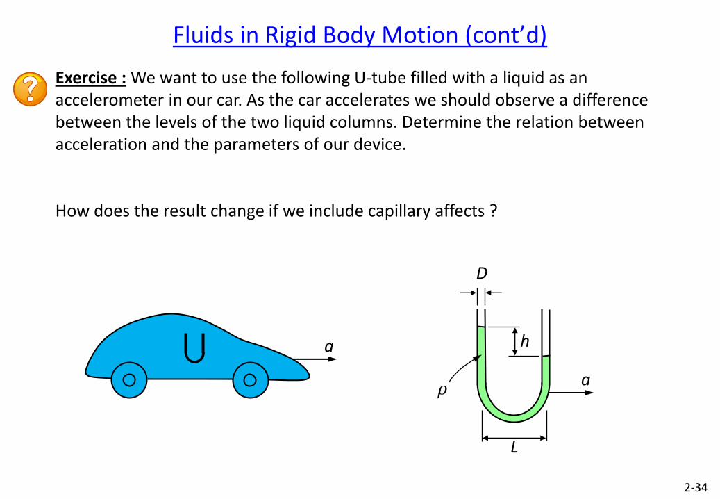
Exercise : We want to use the following U-tube filled with a liquid as an accelerometer in our car. As the car accelerates we should observe a difference between the levels of the two liquid columns. Determine the relation between acceleration and the parameters of our device.
How does the result change if we include capillary affects ?
Fluids in Rigid Body Motion (cont’d)
h
L
𝜌 a
D
a
2-35
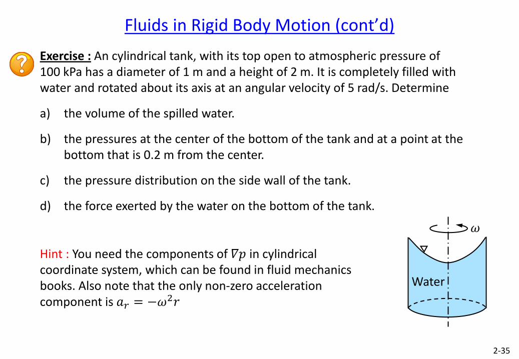
Exercise : An cylindrical tank, with its top open to atmospheric pressure of 100 kPa has a diameter of 1 m and a height of 2 m. It is completely filled with water and rotated about its axis at an angular velocity of 5 rad/s. Determine
a) the volume of the spilled water.
b) the pressures at the center of the bottom of the tank and at a point at the bottom that is 0.2 m from the center.
c) the pressure distribution on the side wall of the tank.
d) the force exerted by the water on the bottom of the tank.
Hint : You need the components of 𝛻𝑝 in cylindrical coordinate system, which can be found in fluid mechanics books. Also note that the only non-zero acceleration component is 𝑎𝑟 = −𝜔