ME 323: Mechanics of Materials Homework Set 8 solutions Fall 2019 Due: Wednesday, October 23 Problem 8.1 (10 points) A steel ( = 30,000 ) square beam with a side length = 2" is subject to loading as shown in Fig. 7.4. Determine the deflection curve of the beam using superposition. Use the table of beam deflections from the R. R. Craig textbook distributed via email. Compare this with the result found using second order integration in Homework 7. Fig. 8.1
Transcript
ME 323: Mechanics of Materials Homework Set 8 solutions
Fall 2019 Due: Wednesday, October 23
Problem 8.1 (10 points)
A steel (𝐸 = 30,000𝑘𝑠𝑖) square beam with a side length𝑎 = 2" is subject to loading as shown in Fig. 7.4. Determine the deflection curve of the beam using superposition. Use the table of beam deflections from the R. R. Craig textbook distributed via email. Compare this with the result found using second order integration in Homework 7.
Fig. 8.1
Solution:
2’
6’
2’
Po = 100 lb/ft
x D
C B
A
(1)
(2)
(3)
=
_
+
𝑙0 = 2𝑓𝑡
4𝑙0 = 8ft
5𝑙0 = 10ft
The following parameters are given
𝑃0 = 100lb/ft
𝐸 = 3 × 10;ksi
𝐼 =112(2)@(2)in; = 1.33in; = 6.4 ∗ 10EFft;
Using the tables and solving for deflections for each of the sections we get the following:
(1)
The deflection for section AB is as follows 𝑣H(𝑥) =
JKLM
N;OP(6𝑙0N − 4𝑙0𝑥 + 𝑥N) , 0 ≤ 𝑥 ≤ 𝑙0
The deflection for the section CD is as follows
𝑣H(𝑥) =(JK)TUV
N;OP(4𝑥 − 𝑙0),𝑙0 ≤ 𝑥 ≤ 5𝑙0
(2)
The deflection for section AC is as follows
𝑣N(𝑥) = −JKLM
N;OP(6(4𝑙0)N − 4(4𝑙0)𝑥 + 𝑥N)
= − JKLM
N;OP(96𝑙0N − 16𝑙0𝑥 + 𝑥N) 0 ≤ 𝑥 ≤ 4𝑙0
The deflection for section CD is as follows
𝑣N(𝑥) = −JK(;TU)V
N;OP(4𝑥 − 4𝑙0), 4𝑙0 ≤ 𝑥 ≤ 5𝑙0
(3)
The deflection for the entire beam AD is given by
𝑣@(𝑥) =XYLM
ZOP(15𝑙0 − 𝑥), 0 ≤ 𝑥 ≤ 5𝑙0
Thus, by principle of superposition we can say that the deflections will be the sum of the deflections from the sections (1), (2) and (3) for the respective ranges of lengths:
JKLM
N;OP(−90𝑙0N + 12𝑙0𝑥) +
XYLM
ZOP(15𝑙0 − 𝑥),0 ≤ 𝑥 ≤ 𝑙0
𝜈(𝑥) = JKN;OP
(4𝑙0@𝑥 − 𝑙0; − 96𝑙0N𝑥N + 16𝑙0𝑥@ − 𝑥;) + XYLM
ZOP(15𝑙0 − 𝑥), 𝑙0 ≤ 𝑥 ≤ 4𝑙0
JKTKV
N;OP(−252𝑥 + 255𝑙0) +
XYLM
ZOP(15𝑙0 − 𝑥), 4𝑙0 ≤ 𝑥 ≤ 5𝑙0
Using the boundary condition that, the deflection at the roller D is 0,𝜈(5𝑙0) = 0 we solve for D]
𝑃0𝑙0@
24𝐸𝐼(−252(5𝑙0) + 255𝑙0) +
25𝐷_𝑙0N(15𝑙0 − 5𝑙0)6𝐸𝐼
= 0
𝑃0𝑙`@
24(−1005𝑙0) +
250𝐷_𝑙0@
6= 0
−1005𝑃 𝑙0; + 1000𝐷_𝑙0@ = 0
𝑫𝒚 = 𝟏.𝟎𝟎𝟓𝑷𝒐𝒍𝒐 = 𝟐𝟎𝟏𝒍𝒃
The final deflection can be described by the following equations:
We can see from the numerical values that the deflection of the three sections of the beams calculated using method of superposition match very closely with the deflections calculated from the method of integration.
Further, if we compare and plot we get the following results.
Problem 8.2 (10 points)
The solid circular rod shown below has an axial force P0 acting at H and an axial force F0 acting at C. All components of the rod are made of steel (E = 200 GPa). Using P0 = 2 kN, F0 = 5 kN, d = 10 mm, and L = 200 mm, determine:
1) The strain energy stored in the rod. 2) The magnitude and direction of the horizontal displacement at H using Castigliano’s
theorem. 3) The magnitude and direction of the horizontal displacement at C using Castigliano’s
theorem.
Fig. 8.2
Solution:
Given:
𝐸 = 200,000MPa
𝑃0 = 2000N, 𝐹0 = 5000N
𝑑 = 10 = 1 × 10ENm
𝐿 = 200mm = 0.2m
𝐴H =𝜋𝑑N
4= 7.85 × 10EFmN
𝐴N = 𝜋𝑑N = 3.14 × 10E;mN
𝐴@ =9𝜋𝑑N
4= 7.065 × 10E;mN
Equilibrium in the shafts gives us following equations:
𝐹H = 𝑃0
𝐹H = 𝐹N = 𝑃0
𝐹@ = 𝑃0 − 𝐹0
To find the strain energy we use the following formulation:
𝑈 =12�
𝐹N
𝐸𝐴𝑑𝑥
�
`
Strain energy in shaft 1:
𝑈H = �𝑃0N
2𝐸𝐴H𝑑𝑥
;�
N�=𝑃0N2𝐿2𝐸𝐴H
= 50.9N.mm
Strain energy in shaft 2:
𝑈N = �𝑃0N
2𝐸𝐴N𝑑𝑥
N�
�=
𝑃0N𝐿2𝐸𝐴N
= 6.4N.mm
Strain energy in shaft 3:
𝑈@ = �(𝑃0 − 𝐹0)N
2𝐸𝐴@𝑑𝑥
�
`=(𝑃0 − 𝐹 )N𝐿2𝐸𝐴@
= 6.4N.mm
Total strain energy can then be calculated to be,
𝑈�0��T = 𝑈H + 𝑈N + 𝑈@ = 63.7N.mm = 0.0637J
To find the displacement at point H we take the partial derivative with respect to the applied force ( 𝑃0 ) at that point and get:
𝑢� =𝛿𝑈�0��T𝛿𝑃0
𝑢� =𝛿𝛿𝑃0
�𝑃0N2𝐿2𝐸𝐴H
+𝑃0N𝐿2𝐸𝐴N
+(𝑃0 − 𝐹 )N𝐿2𝐸𝐴@
�
𝑢� =2𝑃0𝐿𝐸𝐴H
+𝑃0𝐿𝐸𝐴N
+(𝑃0 − 𝐹0)𝐿𝐸𝐴@
𝑢� = 0.053𝑚𝑚 to the left
To find the displacement at point C we take the partial derivative with respect to the applied force at that point ( 𝐹0) and get:
𝑢� =���K�����K
𝑢� =𝛿𝛿𝐹0
�(𝑃0 − 𝐹0)N𝐿2𝐸𝐴@
�
𝑢� = −(𝑃0 − 𝐹0)𝐿𝐸𝐴@
𝑢� = 0.00424𝑚𝑚 to the right
Problem 8.3 (10 points)
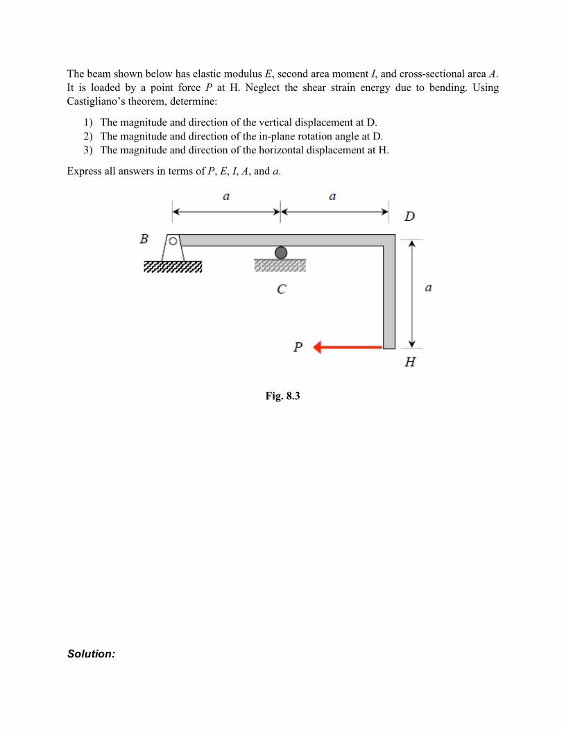
The beam shown below has elastic modulus E, second area moment I, and cross-sectional area A. It is loaded by a point force P at H. Neglect the shear strain energy due to bending. Using Castigliano’s theorem, determine:
1) The magnitude and direction of the vertical displacement at D. 2) The magnitude and direction of the in-plane rotation angle at D. 3) The magnitude and direction of the horizontal displacement at H.
Express all answers in terms of P, E, I, A, and a.
Fig. 8.3
Solution:
In order to find the displacement at D, we apply a dummy moment 𝑀�and a dummy force 𝑃� at point D
Beam BCD is loaded with a distributed load w0 between B and C and a point force P at D. The beam has elastic modulus E and has a square cross section with side length b = L / 10. Neglect the shear strain energy due to bending.
Using Castigliano’s theorem, determine the reactions at the wall at B and the roller at C. Express your answer in terms of w0, P, L, and E.