Page 1
i
DESIGN OF AN EXTERNAL ELEVATOR SYSTEM
FOR YEDITEPE ENGINEERING BUILDING
ME 482 DESIGN OF MECHANICAL SYSTEMS
Term Project Report
Fall 2015
Group Members
President: Tugay TANIK
Notebook Keeper: Berk KÖTEŞLİ
Budget Officer: Doğukan KULUNÇKIRAN
Member: ATIL YÜKSEL
Group 1
Department: Mechanical Engineering
Instructor: Asst. Prof. Namık CIBLAK
15.05.2015
Page 2
ii
Abstract
Capacity of the existing elevators in the Yeditepe University Engineering Building is
not sufficient to satisfy the demand. Teachers, students and other personnel queue up on the
elevators. Therefore, they lose time unnecessarily.
In this report, to solve this problem, an external elevator system was design for
Yeditepe University Engineering Building. Then, necessary components of the elevator were
specified. During the project, all phases of the design were performed and they were shown
in this report.
Page 3
iii
Table of Contents Title Page ................................................................................................... Error! Bookmark not defined.
Abstract ....................................................................................................................................................ii
Table of Content ........................................................................................ Error! Bookmark not defined.
1. Introduction ......................................................................................................................................... 1
2. About Engineering Team .................................................................................................................... 2
3. Statement of the Need ......................................................................................................................... 3
4. Definition of the Problem .................................................................................................................... 4
5. Design Objectives ................................................................................................................................ 5
6. Scope ................................................................................................................................................... 6
7. Project Time Table .............................................................................................................................. 7
8. Design Partition Tree ........................................................................................................................... 8
9. Market Analysis .................................................................................................................................. 9
9.1. Patents ......................................................................................................................................... 9
9.2. Web Pages ................................................................................................................................. 10
9.3. Scientific Papers ....................................................................................................................... 11
10. Survey & Observation ..................................................................................................................... 12
10.1. Survey ...................................................................................................................................... 12
10.2 Observation .............................................................................................................................. 16
11. Preliminary Design Alternatives ..................................................................................................... 17
12. Selected Design ............................................................................................................................... 19
13. Detailed Design ............................................................................................................................... 23
13.1 Elevator Types ......................................................................................................................... 23
13.2. Component Selection .............................................................................................................. 34
13.2.1 Gearless Elevator Machine .............................................................................................. 34
13.2.2 Rope Pulley and Suspension System ............................................................................... 36
13.2.3 Lift System ........................................................................................................................ 37
13.2.4 Brakes ................................................................................................................................ 40
13.2.5 Guide Rails and Rubber .................................................................................................. 41
14. Conclusion ....................................................................................................................................... 42
15. References ....................................................................................................................................... 43
Page 4
1
1. Introduction
Elevator systems are widely used in our daily life. There are several types and
mechanism of the elevator system. In this project, an external elevator system will be
designed to be built on the façade of the Engineering Building of Yeditepe University. The
need is defined as internal elevator systems of the building cannot satisfy the users’ needs in
terms of comfortable usage intensity, fast transportation and elder & disabled people usage.
By using and designing an external elevator system for the Engineering building, a satisfying
solution for this need will be created. Problems, objectives and scopes have been considered
and defined. Also, observations and surveys on the users were done to understand the actual
need and extra modifications. After this statements, literature and market survey have been
completed to get a useful idea for this design. Thus, preliminary designs have been started.
After all several preliminary designs for each components of the external elevator systems,
designed selection have been completed by using priority ranking of design criteria such as
aesthetics, function and cost. Thus, selected design has been developed and mechanic system
selections and calculations have been done.
Page 5
2
2. About Engineering Team
We had an agreement with each team member that our team will be a simulation of an
actual inter – disciplinary engineering team charged with finding solutions to the problems in
this design project. We agree that we are members of a company named ELEVATECH.
Generally this company designs elevator systems and our following project is designing an
external elevator system for Yeditepe Engineering Building.
As a project group we have a division in liabilities. We choose a president, a budget
officer and a notebook keeper in order to maintain the order throughout the design project.
We also agree that in order to create an effective and successful design, all group members’
works will be for improving whole project, not for improving a part of the project.
Our strategy will be sharing our investigations with other team members at that very
moment and sharing opinions on that research together. This cooperation will help us to be up
to date all the time and be more productive. Communication will be managed with e-mail and
group network system in smart phones.
As we have discussed the most critical aim in this project we found that it is finishing
the project within the scheduled time and weekly complete the works and reports without any
delay. We will document all decisions and progresses and archive them both soft and hard.
The Meeting dates will be announced before, so all group members will be attending
the meetings without an excuse. Finally, we will be prioritizing engineering ethics and laws
during the project time.
President: Tugay Tanık
Budget Officer: Doğukan Kulunçkıran
Notebook Keeper: Berk Köteşli
Member: Atıl Yüksel
Page 6
3
3. Statement of the Need
Declaration of the definition of need for an external elevator for Yeditepe
University Engineering Building is given below;
The current elevators inside of the Engineering Building cannot satisfy the users’
needs in terms of comfortable usage intensity, fast transportation and mobility for
elder and disabled people.
In order to build an external elevator system to the exterior facade of the Yeditepe
University Engineering Building to share the intensity of usage of other elevators
inside of the building. Also, would a new external elevator system be designed faster
than the existing ones and become visually pleasing?
Would it be possible to construct this external elevator system in such a way that
mobility and ease of use for elderly and disabled people is provided?
Page 7
4
4. Definition of the Problem
Declaration of the statement of problem for an external elevator for Yeditepe
University Engineering Building is given below;
According to needs of customers, an external elevator system will be built to the
exterior facade of the Yeditepe University Engineering Building by taking into
consideration the needs of users and customers.
This elevator system should be suitable for elderly and disabled people who spend
time into the Yeditepe University.
External elevator should be designed by considering the guidelines, space and
mobility standards and techniques for elderly and disabled people.
External elevator should be play an crucial role on sharing intensity of usage of the
other internal elevators which have already been built into the building
According to survey results which are about current elevators into the building, Load
capacity is set as maximum 6 people however its control system should be design for
working 3-6 people averagely to increase the efficiency of the system.
By using survey results, comfort and visual design of the external elevator should
satisfy the users.
Page 8
5
5. Design Objectives
Declaration of the objectives for an external elevator for Yeditepe University
Engineering Building is given below;
Sizes and location of external elevator should be
designed and selected to share the intensity of
usage of the other internal elevators into the
building.
External elevator should have 3-6 people
capacity for usage according to survey results.
External elevator should be designed to access
desired floors of the building by taking
consideration of the amount of users and
architectural structure and land structure of the
Engineering Building of the Yeditepe University.
Safety and velocity of the elevator should be
preferred according to the technical standards.
Design of the external elevator should be formed
as elegant and satisfying in terms of visual and
technical aspects by considering budget.
External elevator should be designed by
considering the guidelines, space and mobility
standards and techniques for elderly and disabled
people.
Air conditioning should be designed efficiently by considering weather conditions of the
location of the Yeditepe University; because external elevator should not be affected directly
from the outer temperature such as sunlight which causes increasing temperature inside of the
elevator or snow and rain which causes decreases temperature and increases the humidity of
the air inside of the external elevator.
Modern Elevator Design
Page 9
6
6. Scope
Declaration of the scope for an external elevator for Yeditepe University Engineering
Building is given below;
Sizes and location of the external elevator is limited because of the land and architectural
structure of the building. During the surveying process for the location of the elevator,
some unavailable facades of the building were detected. Thus, external elevator should be
designed to locate available facades of the building to reduce the cost of project by
preventing building an extra external structure for the elevator system.
In terms as of providing the visual and technical aspects, transparency concept should be
provided by selecting appropriate material for the system considering performance and
cost of the material in terms of strength, safety, heat transfer, budget, visual aspects etc.
Load capacity is directly related with the sizes. Thus, capacity will be affected location
and sizes of the external elevator. According to survey results, external elevator system
should be design for 3-6 people intervals. Thus, location and sizes should be selecting
according to this scope.
Page 10
7
7. Project Time Table
In this part of the project, time table have been prepared to avoid from the delays on
the project. By using this time table, all steps have been followed by considering the time
intervals.
Figure 7.1: Project Time Table
Page 11
8
8. Design Partition Tree
External elevator system has been investigated by using five main systems which are
sensing, control, electric & electronic, lifting and cabin systems. All components of the
elevator systems were gathered together into these main systems. Using this method gives us
a chance to get extra coordination between the equipment, components and systems. The
partition tree is shown below
Figure 8.1: Design Partition Tree
Page 12
9
9. Market Analysis
Before beginning design process, a lot of literature researches were done about elevator
design. This researches include patents, scientific papers and company web pages. Some of
them are shown as follows:
9.1. Patents
Belt Drive Elevator US1011423 (Dec. 12 1911) Double-effect emergency brake
EP1783087A2 (09.05.2007)
In patent research, some patents were compiled from USPTO and Google Patents.
They are about belt drive elevator, fluid pressure elevator, elevator energy conservation
system, emergency brake system and hydraulic elevator without machine room.
Page 13
10
9.2. Web Pages
In the web pages, there are one elevator company from Turkey, two elevator
companies which are pacesetter from other nations. Also, there are two web pages about
regulations of elevators from ASME and UCTEA chamber of mechanical engineers.
http://www.mmo.org.tr/akm/
(Information about Elevator control center and elevator regulations in Turkey)
---------------------------------------------------------------------------------
http://www.baerasansor.com/
(A Turkish elevator company)
---------------------------------------------------------------------------------
http://www.otisworldwide.com/
(Otis Elevator Company is the world’s largest manufacturer and maintainer of people-
moving products, including elevators, escalators and moving walkways. Otis is a part of UTC
Building & Industrial Systems, a unit of United Technologies Corp., a leading provider to the
aerospace and building systems industries worldwide.)
---------------------------------------------------------------------------------
http://www.schindler.com/us/internet/en/mobility-solutions/products/elevators.html
(Schindler elevators efficiently move passengers in notable buildings across North America,
including hospitals, hotels, offices, residences, airports, arenas and sports facilities. All
Schindler elevators are designed to meet governing safety codes, and meet or exceed
minimum ASME A17.1 codes. They also comply with the Americans with Disabilities Act.)
---------------------------------------------------------------------------------
http://www.kone.com/en/solutions/innovation/
(KONE is the industry forerunner in technological innovations. KONE is committed to
offering high quality, innovative and energy efficient People Flow® solutions that make
travel within and between buildings as smooth as possible.)
---------------------------------------------------------------------------------
https://www.asme.org/about-asme/who-we-are/standards/safety-codes-for-elevators-
and-escalators
(ASME offers the public and private sectors a comprehensive portfolio of codes and standards
offerings, which govern elevators and escalators)
Page 14
11
9.3. Scientific Papers
The articles which were chosen from sciencedirect from our library page contain
general information and history of the elevator, multi direction cable free elevators, energy
consumption of the elevators, the modelling and simulation and of the dynamic responses of
an elevator system, a technic of vibration analysis of the elevators and accessible elevator for
bus.
Multi direction cable free elevator system Accessible elevator for bus
Distribution of the magnetic field induced by the magnets
Finite Element Analysis (FEA) by means of the software FLUX.
Page 15
12
10. Survey & Observation
10.1. Survey
A survey which contains 5 fundamental questions about elevators into the Engineering
Building has been completed. Results were examined on Microsoft Excel and Graphs were
drawn according to these results. Our Survey includes 5 basic questions which are given
below:
1- How often do you use elevators into the Engineering Building?
2- How long do you have to wait to use elevators?
3- Are you content with comfort of the elevators?
4- Are you content with the visual design of the elevators?
5- Do you want a new external elevator to build on the façade of the Engineering
Building? Do you believe that it is necessary?
These 5 questions were answered by using 5 different grading options:
Very Poor Poor Average Good Very Good
According these options, questions were answered. Results and graphs are shown below:
For first question which is:
‘How often do you use elevators into the Engineering Building?’
0
8
Answer
7 7
0
2
4
6
8
10
12
14
16
Çok Az Az Orta Fazla Çok Fazla
Question 1
Kisi
#o
f A
nsw
er
15
Page 16
13
According these options, questions were answered. Results and graphs are shown below:
For second question which is:
‘How much longer do you have to wait to use elevators?’
According these options, questions were answered. Results and graphs are shown below:
For third question which is:
‘Are you contented with comfort of the elevators?’
31
6
19
8
0
2
4
6
8
10
12
14
16
18
20
Çok Az Az Orta Fazla Çok Fazla
Question 2
Kisi
#o
f A
nsw
er
Answer
2 3
23
9
00
5
10
15
20
25
Çok Az Az Orta Fazla Çok Fazla
Question 3
Kisi
#o
f A
nsw
er
Answer
Page 17
14
3
11
19
310
2
4
6
8
10
12
14
16
18
20
Çok Az Az Orta Fazla Çok Fazla
Question 4
Kisi
Answer
#o
f A
nsw
er
5 4 5
11 12
0
2
4
6
8
10
12
14
Çok Az Az Orta Fazla Çok Fazla
Question 5
Kisi
Answer
#o
f A
nsw
er
According these options, questions were answered. Results and graphs are shown below:
For fourth question which is:
‘Are you contented with the visual design of the elevators?’
According these options, questions were answered. Results and graphs are shown below:
For fifth question which is:
‘Do you want to be built a new external elevator to the façade of the Engineering Building?
Do you believe that it is necessary?’
’
Page 18
15
According to these graphs, some inferences were done. First graph gave us an idea
about the intensity of usage of the elevators. Thus we decided maximum load capacity of our
design as 3-6 people.
Also, the most common complaint was waiting the elevators to use. Therefore, we
focused on increasing the velocity and timing performance of our design. Also, some extra
applications can be applied on system to improve usability during intense mobility such as
elevator can be worked between only top floor and ground level.
Thirdly, users are generally contented with the comfort of the elevator such as air
conditioning, lightening and inertial sense due to the acceleration rate of the elevator.
However, we want to develop our design in terms of comfort of the elevator.
4th graph shows that visual design of the elevator system must be improved. Therefore,
just like we said in our objectives, creating an elegant design by using our transparency motto
gives us a chance to provide the visual and technical aspects that we want to see.
Finally, user takes a bright view of an external elevator system to the façade of the
building to share the intensity of usage of other elevators and they support this idea.
Page 19
16
10.2 Observation
Elevator was observed to reach some statistical data between 10:45 - 11:00 AM and 12:00 -
12:16 PM.
Elevator was used by 30 people between 12:00 - 12:16 PM.
Elevator was used by 1.8 people per minute.
Average cycle time of elevator was detected as 2 minutes.
The number of free movement was observed as 3 times.
Average waiting time of people on the ground floor was detected as 1 minute.
Elevator moved from ground floor with 1.5 people as average.
Person or people who do not get on the elevator from ground floor, was not observed.
Overcrowding for elevator could not be observed between 12:00 - 12:16 PM.
Elevator was observed to reach some statistical data between 10:45 - 11:00 AM and 12:00 -
12:16 PM.
Elevator was used by 39 people between 10:45 - 11:00 AM.
Elevator was used by 2.6 people per minute.
Average cycle time of elevator was detected as 2.2 minutes.
The number of free movement was not observed.
Average waiting time of people on the ground floor was detected as 2.2 minute.
Elevator moved from ground floor with 4.4 people as average.
Person or people, who do not get on the elevator from ground floor, were not
observed.
Overcrowding for elevator could not be observed between 10:45 - 11:00 AM.
Page 20
17
11. Preliminary Design Alternatives
When the preliminary design alternatives were produced, a priority ranking has been
voted to define our design criteria and motto. The ranking is shown below.
Table 11.1: Priority Ranking Table
After the selection of the priorty , several alternative design and drawings have been created for each
component of the elevator system such as buttons, control panel, cabin, mechanism, brake system
etc.At the beginnig of the project, transperancy is defined as our design motto.Several design
alternatives produced by considering objectives,scopes and need.The preliminary design examples are
shown below.
Elevator
Criteria Member 1 Member 2 Member 3 Member 4 SUM
~Relative
Weight (%)
Aesthetics 3 3 3 3 12 50
Function 2 1 2 2 7 29
Cost 1 2 1 1 5 21
Transparent Design Emergency Brake System
Page 21
18
In this preliminary design alternatives,
for each components have been considered.
Mechanism has been designed. Also, an self-
cleaning device have been design for the
elevator system because of the fact that the
transparency was the most critical design
criteria for our external elevator system and
system has to be made of transparent material
such as tempered glass etc. After all these
alternative designs, the final design is selected
and developed.
Self-Cleaning Device Regulatable Counterweight
Slider Mechanism
Page 22
19
12. Selected Design
During the design process of the external elevator, the architecture of the Engineering
Building was taken into consideration to be suitable for architecture of the building. Also,
design of the external elevator should enrich the architectural view of the Engineering
Building. Therefore, Seljuk (Selçuklu) architecture which is used on all buildings of the
university was selected as design criteria of the external elevator system. Low roof design
with red tiles, wood L-shaped puncheons, embossment and engraving, archway and double-
headed eagle, which is a symbol of the Seljuk culture, will be applied on this design of the
elevator. Likewise, a spacious and modern atmosphere will be formed by using together water
resistant woods for floor and ceiling of elevator cabin and mirrors for the walls for the
elevator cabin.
Machine room of the elevator system is placed the top of the system. Machine room
ventilation is provided by air duct which located side of it. At the bottom part of the system,
outside door and safety cab which are made of tempered glass disallow person entry under the
elevator. Also, outside door is only used for ground floor/basement entrance. Inside door
which located in side of the cabin is only used and activated for floors which are called as
mezzanine floors.
Front of the main entrance door was selected as location of the external elevator
because of the fact that the most commonly used entrance of the building by people is main
entrance door. This location provides to service 6 floors of the building externally. Also, at
this location, design of the external elevator overlaps with the architecture of the building.
Figure 12.1: GENERAL CONCEPT
Page 23
20
Figure 12.2: CABIN DESIGN
Page 24
21
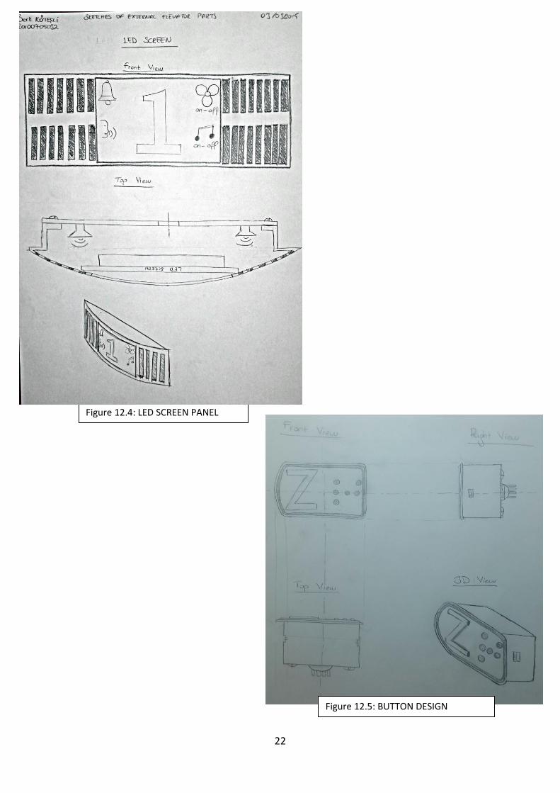
During the design of control panel and buttons of the external elevator, visuality and
multi-functionality were taken into consideration. Buttons and Screen has been designed
canorously with the architecture and design of the building and external elevator system.
Number of buttons was determined by considering number of floors and other functions such
as air ventilation, alarm, communication system and multifunctional door buttons.
Buttons were designed for also considering
elder and disabled people. Therefore, braille which
is a type of alphabet for blind people was added to
the design of the buttons. Also, interactive voice
system which announces the floors and other
actions to the disabled people is added to the
system. Thus, external elevator system became
much more suitable for disable people. Screen of
the control panel was design to observe actions.
All functions can be controlled by observing the
screen. Also two speakers were located in both
side of the screen panel. Thus, actions and floors
can be announced.
Radio broadcast was added to the system to
increase the motivation and comfort of the users.
Other feature of the control panel is air ventilation
system. For cold or hot seasons, air ventilation
system provides the optimum temperature for the
external elevator cabin and users.
Automation system of the external elevator system
was designed carefully. User comment will be
read and automation system was programmed to
make a decision for direction of the movement of
the cabin.
Figure 12.3: CONTRTOL PANEL
Page 25
22
Figure 12.4: LED SCREEN PANEL
Figure 12.5: BUTTON DESIGN
Page 26
23
13. Detailed Design
13.1 Elevator Types
Elevators are categorized according to hoist mechanism to 4 main types:
1. Hydraulic Elevators
2. Pneumatic Elevators
3. Climbing elevator
4. Traction Elevators
1- Hydraulic Elevators
In hydraulic elevators, there is a piston at the bottom of the elevator that pushes the elevator
up. Hydraulic elevators are used for low-rise applications. The machine room for hydraulic
elevators is located at the ground of the elevator shaft.
Hydraulic Elevators
Page 27
24
Hydraulic elevators are divided to two main types:
A- Holed Hydraulic Elevators
Holed hydraulic elevators have a sheave that extends below the floor of the elevator pit. This
sheave accepts the retracting piston as the elevator descends.
Holed (Conventional) Hydraulic Elevators
Page 28
25
B- Hole-less Hydraulic Elevators
Hole-less hydraulic elevators have a piston on two side of the cab. There are 3 type of the
hole-less elevators:
a- Telescopic Hydraulic Elevators:
Telescopic hydraulic elevators have the telescoping pistons which are fixed at the base of the
pit. The telescopic elevators do not require a sheave or hole below the pit and they have 2 or 3
pieces of telescopic pistons.
Telescopic Hydraulic Elevators
Page 29
26
b- Non-telescopic (single stage) Hydraulic Elevators:
Non-telescopic elevators have one piston on the each side of the cab.
Non-telescoping (single stage) Hydraulic Elevators
Page 30
27
c- Roped Hydraulic Elevators
Roped hydraulic elevators use a combination of ropes and a piston to move the elevator.
Roped Hydraulic Elevators
.
Page 31
28
2- Pneumatic Elevators
Pneumatic elevators are raised and lowered by controlling air pressure in a chamber in which
the elevator sits.
Pneumatic Elevators
Page 32
29
3- Climbing elevator
Climbing elevator is a self-ascending elevator with its own propulsion. Mostly electric or
combustion engine are used for propulsion. Climbing elevators are often used in work and
construction areas.
Climbing elevator
Page 33
30
4- Traction Elevators (Pull Elevators)
Traction elevators are lifted by ropes which pass over a wheel attached to an electric motor
above the elevator shaft. They are used for mid and high-rise applications and have much
higher travel speeds than hydraulic elevators. A counter weight makes the elevators more
efficient.
Traction Elevators (Pull Elevators)
Page 34
31
Traction elevators have 3 main types as follows:
A- Geared Traction Elevators:
Geared traction elevators have a gearbox that is attached to the motor which drives the wheel
that moves the ropes.
Geared Traction Elevators
Page 35
32
B- Gear-less Traction Elevators:
Gear-less traction elevators have the wheel attached directly to the motor.
Gear-less Traction Elevators
Page 36
33
C- Machine Room-Less Elevators:
Machine room-less elevators are typically traction elevators that do not have a machine room
above the elevator shaft. The machine sits on the elevator shaft.
Machine Room-Less Elevators
In this project, machine room-less elevator type was selected and all components of
the elevator were chosen to be appropriate for it.
Page 37
34
13.2. Component Selection
13.2.1 Gearless Elevator Machine
Parts of the gearless elevator machine:
ZETATOP SM160 was selected as gearless elevator machine.
ZETATOP SM160
Components of a gearless elevator machine (www.ziehl-abegg.com)
Page 38
35
Technical specifications of the motor were given below tables. Highlighted options
were selected.
Page 39
36
13.2.2 Rope Pulley and Suspension System
Elevator Rope Pulley (www.ziehl-abegg.com)
Elevator Suspension (http://www.contitech.de) 2:1 Elevator suspension system
(www.ziehl-abegg.com)
For reducing the weight of the
counterweight and increasing the
torque 2:1 (Half-wrap) suspension was
selected.
Page 40
37
13.2.3 Lift System
Lifting system plays a very important role in this course project which was designed
external elevator system for Yeditepe University. There are 2 types of hoist mechanisms.
These are traction and hydraulic elevator.
Traction elevator is divided into two parts as geared and gearless. Geared traction
machines are driven by AC or DC electric motors and it uses worm gears to control
mechanical movement of elevator cabin. The electric motor in this design drives a worm-and-
gear-type reduction unit, which turns the hoisting sheave which is connected to a gearbox,
driven by a high-speed motor. These machines are generally used for up to 3 m/s speeds.
Gearless traction machines have low-RPM and high-torque electric motors which are
energized by AC or DC. It has five to eight lengths of wire cable which is known as wire
ropes, are connected to the top of the elevator and revolves the drive sheave in grooves.
Gearless traction elevators reach speeds of up to 10 m/s or even higher.
Geared Traction Machine Gearless Traction Machine
Page 41
38
The hydraulic elevator has dominated the low-rise market because it is cheaper to
build, install and service, and because it has a decidedly better safety record than the electric
elevator. Especially in earthquake endangered areas, the hydraulic elevator has proven itself
to be clearly the safer option.
Hydraulic Elevator System
Some studies in residential elevator lifting technology helped improvement of basic
mechanical parts and safety features. In this design project, gearless traction machine was
used because of many advantages and PU (Polyurethane) coated belt system was used instead
of steel rope system result of group voting.
Page 42
39
The innovation provided by using of polyrope instead of steel rope, is a revolution on
the elevator technology. This innovation causes fundamental changes on elevator
performance. PU coated belt system is better driving ability than steel rope system. It has
larger load capacity, small motor sizes and machine roomless system. It provides high
efficient due to lower power consumption. It requires less power inverter. It provides better
corrosion resistance due to PU coating. Besides it reduces noise by preventing the friction
between steel ropes and presents us system course comfortably.
PU Coated Steel Rope
Page 43
40
13.2.4 Brakes
The most common elevator brake is made up of brake shoes with linings, a solenoid
assembly and a compressive spring assembly. This brake must be capable of stopping the
machine when the elevator cabin with 125 % of rated load is travelling at its rated speed and
must hold the system at rest afterwards. Zinc bonded asbestos-material which has a high
coefficient of friction, is used to improve the stopping ability in the breaks and if this material
has too high a coefficient of friction, jerky motion can be occurred in the elevator cabin.
There are 3 types of brakes which are used in the elevator systems. These are drum,
disc and band brakes but band brakes are not preferred. In this design project, drum brakes
was chosen result of voting because of many advantages. A drum brake system contains an
electromagnetic brake, consisting of a spring assembly, two brake shoes with linings and a
magnet assembly. Disc brakes have smaller and lighter hydraulic cylinders. Their wheel
calipers are somewhat simpler to recondition compared to calipers. It has built-in self-
energizing effect requires less input force such as hydraulic pressure. Drum brakes are less
expensive to produce and it has slightly lower frequency of maintenance due to better
corrosion resistance compared to disc brake system.
Drum Brake Components
Page 44
41
13.2.5 Guide Rails and Rubber
Roller guides in the elevator system travel along rails in the hoist way so the elevator cabin
can moves properly without any damage. They provides comfortably elevator travel by
proven to reduce lateral vibration by as much as 50 %.
Neoprene rubber roller wheels are optimized for maximum ride comfort and minimal noise.
Neoprene compound provides the damping characteristics essential to ride quality in
passenger applications. Besides, roller guides are easy-to-install package and. They have ease
of interference and fully adjustable stabilizing springs
Roller Guide Guide Rail
Page 45
42
14. Conclusion
In this project, an external elevator system for engineering building of Yeditepe
University has been designed by following all phases of design. Statement of need is
understood. Problem, scope, objectives were defined. A detailed literature survey and
observation have been completed. By using these results, alternative drawings and designs
were created. Most suitable design for each component is selected by voting method in our
team. Selected design was improved and calculations have been completed .All components
and equipment was selected by using these calculations. Thus, an efficient, visually pleasing,
economical and suitable design for elder and disabled people was created by using design
phases. Consequently, this project gives us a chance to improve our engineering skill and
procedure significance.
Page 46
43
15. References
http://en.wikipedia.org/wiki/Elevator#Climbing_elevator
http://en.wikipedia.org/wiki/Elevator
http://www.archtoolbox.com/materials-systems/vertical-circulation/elevatortypes.html
http://www.electrical-knowhow.com/2012/04/elevators-types-and-classification-part.html
http://www.ziehl-abegg.com/ww/misc-205-Drive-Technology-for-elevators.html