ME417 INTERNAL COMBUSTION ENGINES CO1 Study the working of SI and CI Engines and its components. CO2 Prepare and analyze valve timing diagrams and heat balance sheet. CO3 Understand and estimate the effects of variation in properties of air at various states. CO4 Carry out tests on I. C. Engines and calculate its efficiencies and performance parameters at various running conditions. CO5 Learn about the advanced technologies and research areas in engines. List of Experiment (ME417 Internal Combustion Engines) Sr. No. Title Course Outcomes 1 Comparison of S.I and C.I Engines CO1 2 Combustion Chambers CO3 3 Types of Carburetor CO1 4 Ignition System CO5 5 Fuel Injection System CO5 6 Single Cylinder Four Stroke Diesel Engine CO2, CO4 7 Four Cylinder Four Stroke Diesel Engine CO2, CO4 8 Single Cylinder Four Stroke Petrol Engine CO2, CO4 9 Single Cylinder Two Stroke Petrol Engine CO2, CO4 10 Valve Timing Diagram CO2
Transcript
ME417 INTERNAL COMBUSTION ENGINES
CO1 Study the working of SI and CI Engines and its components.
CO2 Prepare and analyze valve timing diagrams and heat balance sheet.
CO3 Understand and estimate the effects of variation in properties of air at various states.
CO4 Carry out tests on I. C. Engines and calculate its efficiencies and performance
parameters at various running conditions.
CO5 Learn about the advanced technologies and research areas in engines.
List of Experiment (ME417 Internal Combustion Engines)
Sr.
No. Title Course Outcomes
1 Comparison of S.I and C.I Engines CO1
2 Combustion Chambers CO3
3 Types of Carburetor CO1
4 Ignition System CO5
5 Fuel Injection System CO5
6 Single Cylinder Four Stroke Diesel Engine CO2, CO4
7 Four Cylinder Four Stroke Diesel Engine CO2, CO4
8 Single Cylinder Four Stroke Petrol Engine CO2, CO4
9 Single Cylinder Two Stroke Petrol Engine CO2, CO4
10 Valve Timing Diagram CO2
CHAROTAR UNIVERSITY OF SCIENCE & TECHNOLOGY
FACULTY OF TECHNOLOGY & ENGINEERING
CHAMOS Matrusanstha Department of Mechanical Engineering.
Name of Subject: Internal Combustion Engines (ME-417)
INDEX
Sr.
No.
Performance
Date Title
No.
of
Pages
Marks Assessment
Date
Sign of
Faculty
1 Comparison of S.I and C.I
Engines
2 Combustion Chambers
3 Types of Carburetor
4 Ignition System
5 Fuel Injection System
6 Single Cylinder Four Stroke
Diesel Engine
7 Four Cylinder Four Stroke
Diesel Engine
8 Single Cylinder Four Stroke
Petrol Engine
9 Single Cylinder Two Stroke
Petrol Engine
10 Valve Timing Diagram
CHAROTAR UNIVERSITY OF SCIENCE & TECHNOLOGY
FACULTY OF TECHNOLOGY & ENGINEERING
CHAMOS Matrusanstha Department of Mechanical Engineering
Page 1 of 23
Internal Combustion Engines (ME-417) Date:
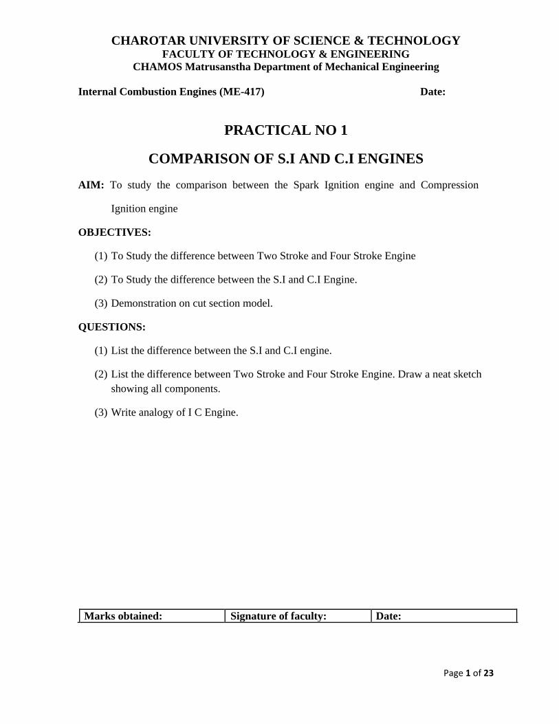
PRACTICAL NO 1
COMPARISON OF S.I AND C.I ENGINES
AIM: To study the comparison between the Spark Ignition engine and Compression
Ignition engine
OBJECTIVES:
(1) To Study the difference between Two Stroke and Four Stroke Engine
(2) To Study the difference between the S.I and C.I Engine.
(3) Demonstration on cut section model.
QUESTIONS:
(1) List the difference between the S.I and C.I engine.
(2) List the difference between Two Stroke and Four Stroke Engine. Draw a neat sketch
showing all components.
(3) Write analogy of I C Engine.
Marks obtained: Signature of faculty: Date:
CHAROTAR UNIVERSITY OF SCIENCE & TECHNOLOGY
FACULTY OF TECHNOLOGY & ENGINEERING
CHAMOS Matrusanstha Department of Mechanical Engineering
Page 2 of 23
Internal Combustion Engines (ME-417) Date:
PRACTICAL NO 2
COMBUSTION CHAMBERS AIM: To Study of Combustion Chambers.
(A) To Study of Combustion Chambers for Spark Ignition Engine
OBJECTIVES:
(1) To understand combustion process in S.I engines
(2) To understand different type of combustion chambers
QUESTIONS:
(1) What are the basic requirements of a good combustion chamber?
(2) Explain combustion chamber design principal
(3) Classification of combustion chamber.
(4) Explain different types of combustion chamber.
(5) Draw a neat sketch of combustion chamber of 4-stroke and 2-stroke engine.
(B) To Study of Combustion Chamber for Compression Ignition Engine.
OBJECTIVES:
(1) To understand the combustion processes in C.I. engine.
(2) To understand the different types of combustion chamber in C.I. Engine.
QUESTIONS:
(1) Classification of Combustion chamber in case of C.I. Engine.
(2) Explain different types of combustion chamber in C.I. Engine.
Marks obtained: Signature of faculty: Date:
CHAROTAR UNIVERSITY OF SCIENCE & TECHNOLOGY
FACULTY OF TECHNOLOGY & ENGINEERING
CHAMOS Matrusanstha Department of Mechanical Engineering
Page 3 of 23
Internal Combustion Engines (ME-417) Date:
PRACTICAL NO 3
TYPES OF CARBURETOR AIM: Study of Different Types of Carburetor in S.I. Engine.
OBJECTIVE: Understand a carburetion process and learn about different type of carburetors.
QUESTIONS: (1) Derive the equation for simple carburetor and put your comments on it.
(2) Write the shot note on the complete carburetor.
(3) Write a shot note with neat sketch on the following carburetor.
(a) Solex Carburetor
(b) S.U. Carburetor
(c) Carter Carburetor
(4) Write a note in brief for Petrol Injection system.
Marks obtained: Signature of faculty: Date:
CHAROTAR UNIVERSITY OF SCIENCE & TECHNOLOGY
FACULTY OF TECHNOLOGY & ENGINEERING
CHAMOS Matrusanstha Department of Mechanical Engineering
Page 4 of 23
Internal Combustion Engines (ME-417) Date:
PRACTICAL NO 4
IGNITION SYSTEM
AIM: Study of Ignition Systems in I.C. Engine.
OBJECTIVE: Understand ignition systems in I.C engine.
CHAMOS Matrusanstha Department of Mechanical Engineering
Page 5 of 23
Internal Combustion Engines (ME-417) Date:
PRACTICAL NO 5
FUEL INJECTION SYSTEM AIM: Study of Fuel Injection Systems in C. I. Engine.
OBJECTIVE: Understand Fuel Injection systems & working and construction of Injector and Fuel
Pump.
QUESTIONS:
(1) Requirements of good diesel Injection system.
(2) Types of Injection system
(3) Explain types of Nozzles
(4) Write a shot note of Fuel Pump (working and construction with neat sketch)
Marks obtained: Signature of faculty: Date:
CHAROTAR UNIVERSITY OF SCIENCE & TECHNOLOGY
FACULTY OF TECHNOLOGY & ENGINEERING
CHAMOS Matrusanstha Department of Mechanical Engineering
Page 6 of 23
Internal Combustion Engine (ME-417) Date:
PRACTICAL NO 6
SINGLE CYLINDER FOUR STROKE DIESEL ENGINE
AIM: Performance test on four-stroke single-cylinder diesel engine with eddy current
dynamometer.
OBJECTIVE:
To perform test on four-stroke single cylinder diesel engine with eddy current
dynamometer to understand its operational characteristics.
SPECIFICATIONS: Type: Four Stroke Single Cylinder Diesel Engine Make: Kirloskar model JAV1 Bore: 85 mm Stroke: 80 mm RPM: 1500 BHP: 5 HP, 3.7 KW Fuel: High Speed Diesel oil Sp. Gr.: 0.83 C.V: 10,833 Kcal/kg
PRECAUTIONS: It is strongly recommended that the operator is familiar with the engine before it is
started. Before the engine is started, check the lubricating oil level I the crank case and
add oil if required. All recommended periodic maintenance and service in the manual
must be carried out for the engine.
At any time either the radiator or the external cooling water line is to be used. Both
cannot be used at the same time. When external cooling water is used, radiator valves
should be closed to avoid leakage or even rupture due to high-pressure water supply.
CHAROTAR UNIVERSITY OF SCIENCE & TECHNOLOGY
FACULTY OF TECHNOLOGY & ENGINEERING
CHAMOS Matrusanstha Department of Mechanical Engineering
Page 7 of 23
Do not operate the exhaust gas calorimeter without water as the brazing used for
copper tubes in the heat exchanger will melt at full load engine exhaust temperature
(over 400-500 deg C)
PROCEDURE: Check fuel level.
Check lubrication oil level.
Open the three way cock so that fuel flows to the engine directly from the tank.
Open the cooling water valves and ensure that water flows through the engine.
Open the water line to the hydraulic dynamometer.
Keep the loading in the hydraulic dynamometer at minimum.
Start the engine. If the engine is cold, press the heater button until the glow indicator
glows and then start the engine. Operate the throttle valve so that the engine picks up the speed to the required level,
say 1500 rpm. Load engine with the hydraulic dynamometer loading is achieved by turning the
handle in the direction marked. If sufficient load is not absorbed by the dynamometer
at the required speed, the outlet valve in the dynamometer can be closed to increase the
pressure (as indicated by the pressure gauge) and hence the load. When engine is loaded the speed will decrease. Hence open the throttle to increase the
speed. When steady condition is reached, the cooling water temperature is maintained at the
required level by adjusting the flow rate. Measure the flow rate. Adjust the cooling water flow rate in the exhaust gas calorimeter to achieve steady
state condition.
CHAROTAR UNIVERSITY OF SCIENCE & TECHNOLOGY
FACULTY OF TECHNOLOGY & ENGINEERING
CHAMOS Matrusanstha Department of Mechanical Engineering
Page 8 of 23
OBSERVATION TABLE:
Sr. No. Particulars 1 2 3 4 5
1 Engine Speed (N rpm)
2 Hydraulic Dynamometer Load (W
kg)
3 Engine Output (KW)
4 Time for 10 cc of fuel consumption
(Sec)
5 Engine input (KW)
6 Thermal Efficiency %
Air Tank Measurement:
Orifice Water Manometer Reading h1 =________ cm of water
Orifice Water Manometer Reading h2 =________ cm of water
Difference in water level ∆h =________ cm of water
Exhaust gas calorimeter readings: Engine cooling water inlet temperature T1=_____
Engine cooling water outlet temperature T2=_____
Calorimeter cooling water inlet temperature T3=_____
Calorimeter cooling water outlet temperatureT4=_____
Exhaust gas inlet temperature T5=_____
Exhaust gas outlet temperature T6=_____
Room Temperature T7=_____
Engine cooling water flow rate We=_____
Calorimeter cooling water flow meter Wc=______
CHAROTAR UNIVERSITY OF SCIENCE & TECHNOLOGY
FACULTY OF TECHNOLOGY & ENGINEERING
CHAMOS Matrusanstha Department of Mechanical Engineering
Page 9 of 23
Length of torque arm L = 0.146 m
Load W =_______
Torque T = 9.81 ×W ×L= ___________
Engine speed N = ___________
Engine output =
= ________ KW
Time for 10cc of fuel consumption t =________
Fuel consumption per minute Q= =__________ cc/min
Total fuel consumption=
=_________ kg/min
Heat input = total fuel consumption C.V = __________ Kcal/min
Input power = = _________
Engine efficiency =
=__________
Equivalent air column =
= __________
Orifice diameter= d =0.035 m
Area of orifice= 0.962 10-3
m2
Volume of air= Va=Cd × Area of orifice × (2gh)0.5
= __________
Weight of intake air=1.2 × Va = __________ kg/sec
Theoretical volume of air = Vt =
=__________
Volumetric efficiency =
=___________
Air fuel ratio = _________
CHAROTAR UNIVERSITY OF SCIENCE & TECHNOLOGY
FACULTY OF TECHNOLOGY & ENGINEERING
CHAMOS Matrusanstha Department of Mechanical Engineering
Page 10 of 23
GRAPH:
Draw the graph of Vs Load, Brake power
CONCLUSION:
Marks obtained: Signature of faculty: Date:
CHAROTAR UNIVERSITY OF SCIENCE & TECHNOLOGY
FACULTY OF TECHNOLOGY & ENGINEERING
CHAMOS Matrusanstha Department of Mechanical Engineering
Page 11 of 23
Internal Combustion Engine (M-709) Date:
PRACTICAL NO 7
FOUR CYLINDER FOUR STROKE DIESEL ENGINE
AIM: Performance test on four-stroke four-cylinder diesel engine with hydraulic
dynamometer.
OBJECTIVE:
To perform test on four-stroke four cylinders diesel engine with hydraulic
dynamometer to understand its operational characteristics.
SPECIFICATIONS:
Type: Four Stroke Four Cylinder Diesel Engine
Make: HM Trekker
Bore: 73 mm
Stroke: 90 mm
Capacity: 1500 cc
RPM: 1500
BHP: 10 HP @ 1500 rpm
Fuel: High Speed Diesel oil
Sp. Gr.: 0.83
C.V: 10,833 Kcal/kg
PRECAUTIONS:
It is strongly recommended that the operator is familiar with the engine before it is
started. Before the engine is started, check the lubricating oil level in the crankcase and
add oil if required. All recommended periodic maintenance and service in the manual
must be carried out for the engine.
At any time either the radiator or the external cooling water line is to be used. Both
cannot be used at the same time. When external cooling water is used, radiator valves
should be closed to avoid leakage or even rupture due to high-pressure water supply.
Abhishek D S
Strikeout
Abhishek D S
Highlight
Abhishek D S
Typewriter
(ME417)
CHAROTAR UNIVERSITY OF SCIENCE & TECHNOLOGY
FACULTY OF TECHNOLOGY & ENGINEERING
CHAMOS Matrusanstha Department of Mechanical Engineering
Page 12 of 23
Do not operate the exhaust gas calorimeter without water as the brazing used for
copper tubes in the heat exchanger will melt at full load engine exhaust temperature
(over 400-500 deg C)
PROCEDURE:
Check fuel level.
Check lubrication oil level.
Open the three way cock so that fuel flows to the engine directly from the tank.
Open the cooling water valves and ensure that water flows through the engine.
Open the water line to the hydraulic dynamometer.
Keep the loading in the hydraulic dynamometer at minimum.
Start the engine. If the engine is cold, press the heater button until the glow indicator
glows and then start the engine.
Operate the throttle valve so that the engine picks up the speed to the required level,
say 1500 rpm.
Load engine with the hydraulic dynamometer loading is achieved by turning the
handle in the direction marked. If sufficient load is not absorbed by the dynamometer
at the required speed, the outlet valve in the dynamometer can be closed to increase the
pressure (as indicated by the pressure gauge) and hence the load.
When engine is loaded the speed will decrease. Hence open the throttle to increase the
speed.
When steady condition is reached, the cooling water temperature is maintained at the
required level by adjusting the flow rate. Measure the flow rate.
Adjust the cooling water flow rate in the exhaust gas calorimeter to achieve steady
state condition.
OBSERVATION TABLE:
Sr. No. Particulars 1 2 3 4 5
1 Engine Speed (N rpm)
2 Hydraulic Dynamometer Load (W kg)
3 Engine Output (KW)
4 Time for 10 cc of fuel consumption
(Sec)
5 Engine input (KW)
6 Thermal Efficiency %
CHAROTAR UNIVERSITY OF SCIENCE & TECHNOLOGY
FACULTY OF TECHNOLOGY & ENGINEERING
CHAMOS Matrusanstha Department of Mechanical Engineering
Page 13 of 23
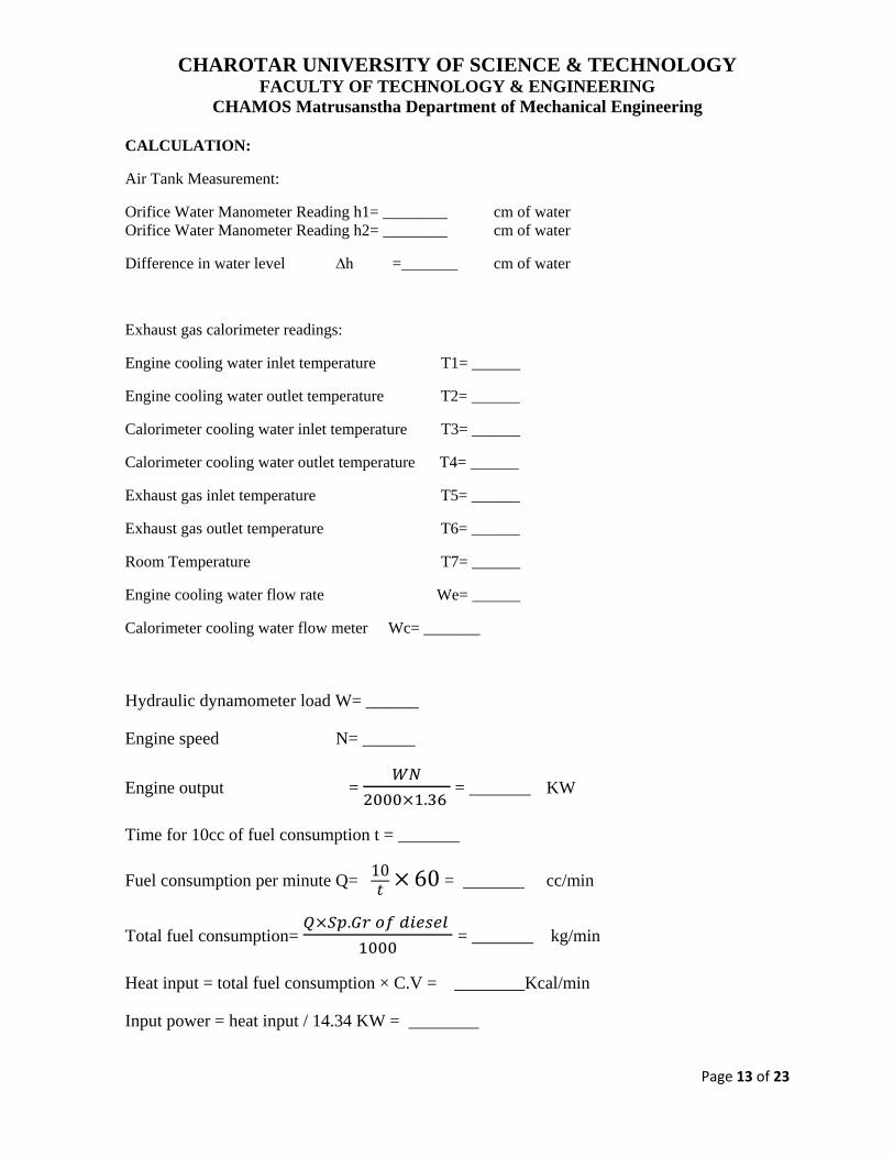
CALCULATION:
Air Tank Measurement:
Orifice Water Manometer Reading h1= ________ cm of water
Orifice Water Manometer Reading h2= ________ cm of water
Difference in water level ∆h =_______ cm of water
Exhaust gas calorimeter readings:
Engine cooling water inlet temperature T1= ______
Engine cooling water outlet temperature T2= ______
Calorimeter cooling water inlet temperature T3= ______
Calorimeter cooling water outlet temperature T4= ______
Exhaust gas inlet temperature T5= ______
Exhaust gas outlet temperature T6= ______
Room Temperature T7= ______
Engine cooling water flow rate We= ______
Calorimeter cooling water flow meter Wc= _______
Hydraulic dynamometer load W= ______
Engine speed N= ______
Engine output =
= _______ KW
Time for 10cc of fuel consumption t = _______
Fuel consumption per minute Q= = _______ cc/min
Total fuel consumption=
= _______ kg/min
Heat input = total fuel consumption × C.V = ________Kcal/min
Input power = heat input / 14.34 KW = ________
CHAROTAR UNIVERSITY OF SCIENCE & TECHNOLOGY
FACULTY OF TECHNOLOGY & ENGINEERING
CHAMOS Matrusanstha Department of Mechanical Engineering
Page 14 of 23
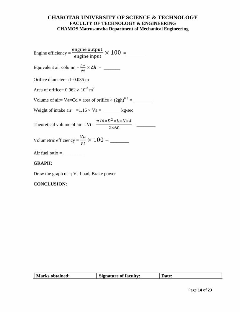
Engine efficiency =
= ________
Equivalent air column =
= _______
Orifice diameter= d=0.035 m
Area of orifice= 0.962 × 10⁻³
m2
Volume of air= Va=Cd × area of orifice × (2gh)0.5
= ________
Weight of intake air =1.16 × Va = ________kg/sec
Theoretical volume of air = Vt =
= ________
Volumetric efficiency =
= ______
Air fuel ratio = _________
GRAPH:
Draw the graph of Vs Load, Brake power
CONCLUSION:
Marks obtained: Signature of faculty: Date:
CHAROTAR UNIVERSITY OF SCIENCE & TECHNOLOGY
FACULTY OF TECHNOLOGY & ENGINEERING
CHAMOS Matrusanstha Department of Mechanical Engineering
Page 15 of 23
Internal Combustion Engine (M-709) Date:
PRACTICAL NO 8
SINGLE CYLINDER FOUR STROKE PETROL ENGINE
AIM: Performance test on four-stroke single-cylinder petrol engine with eddy current
dynamometer.
OBJECTIVE:
To perform test on four-stroke single cylinder petrol engine with eddy current
dynamometer to understand its operational characteristics.
SPECIFICATIONS:
Make: Greaves
Type: four stroke single cylinder vertical petrol engine
Power: 2.9 KW
Speed: 3000 rpm
PRECAUTION:
Check water supply and crankcase oil level starting the engine.
Never stop the engine on load
Do not put hand in water rheostat while in operation
Do not close the orifice while engine is in operation
Add salt in water rheostat incorrect percentage
After completion of experiment drain all water
PROCEDURE:
Fill up sufficient petrol in tank without oil
Check oil level in the crankcase of the engine. It is lesser than H on dipstick level it up
to the mark with clean SAE-40oil
Fill up water in water rheostat to a required height and add salt. (Approximately 50 gm
in filled water tank)
Fill up water in manometer up to half of the height. Put off main switch o rheostat and
ignition switch o engine is ON
Abhishek D S
Typewriter
(ME417)
Abhishek D S
Highlight
CHAROTAR UNIVERSITY OF SCIENCE & TECHNOLOGY
FACULTY OF TECHNOLOGY & ENGINEERING
CHAMOS Matrusanstha Department of Mechanical Engineering
Page 16 of 23
Start water supply to calorimeter
Wind the starting rope over the starting drum and give a brisk pull. Initially, it may
require operating the choke, if the engine is cold. As the engine starts put the choke
off. Put on main switch.
Slowly rotate the loading knob (on panel) in clockwise direction so that the engine
gets loaded, say 2 amps
Fill the burette with burette filling cock. Close the cock in fuel line coming from fuel
tank note down time for 10 ml fuel consumption, manometer difference, ammeter and
voltmeter reading and calorimeter water flow
Note down the temperature from T1 to T4
Repeat the procedure for difference loads. Maximum load is 8 amps.
OBSERVATION TABLE:
Sr. No 1 2 3 4
Brake Drum Speed N rpm
Ammeter I amp
Voltmeter V volt
Time for 10 ml of fuel tf sec
Manometer diff. hw cm
Time for 1 lit. Calorimeter water tw
sec
Temperatures:
Water inlet to calorimeter T1 deg C
Water outlet from calorimeter T2
deg C
Exhaust gas before calorimeter T3
deg C
Exhaust gas after calorimeter T4
deg C
CHAROTAR UNIVERSITY OF SCIENCE & TECHNOLOGY
FACULTY OF TECHNOLOGY & ENGINEERING
CHAMOS Matrusanstha Department of Mechanical Engineering
Page 17 of 23
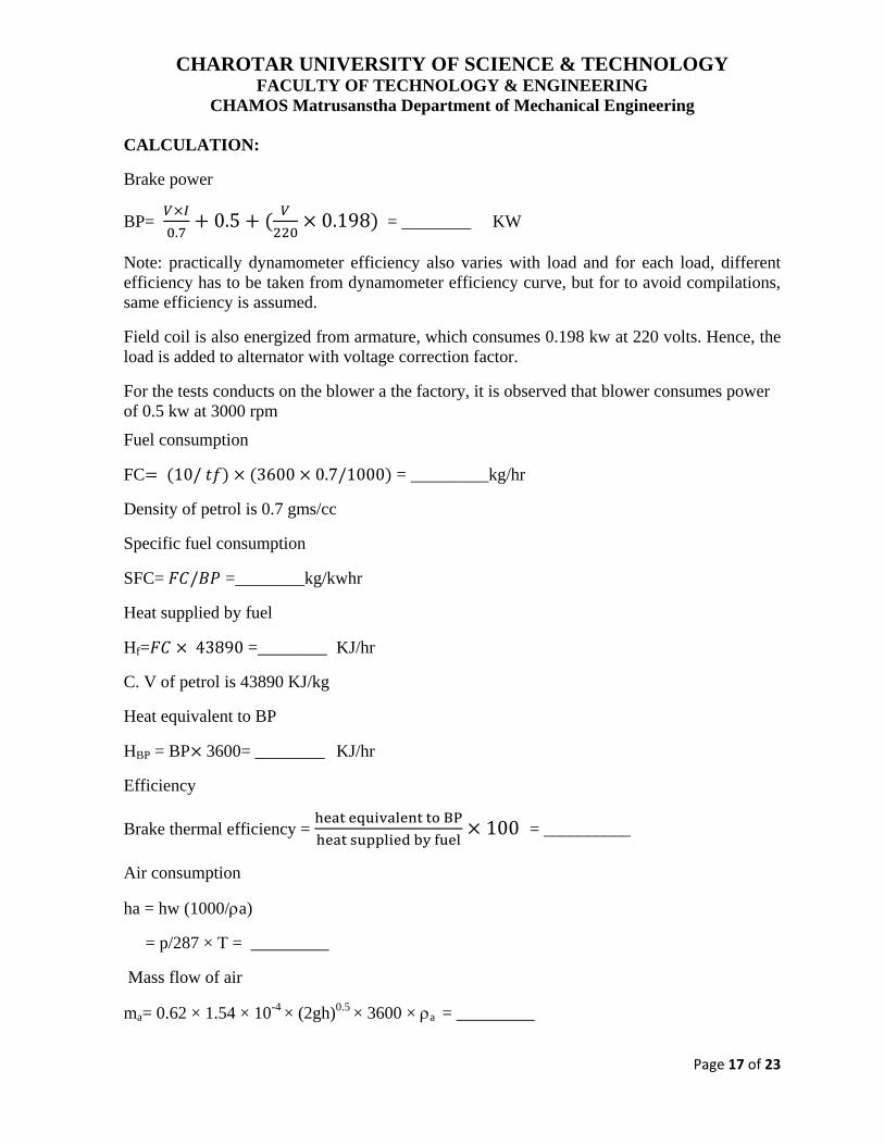
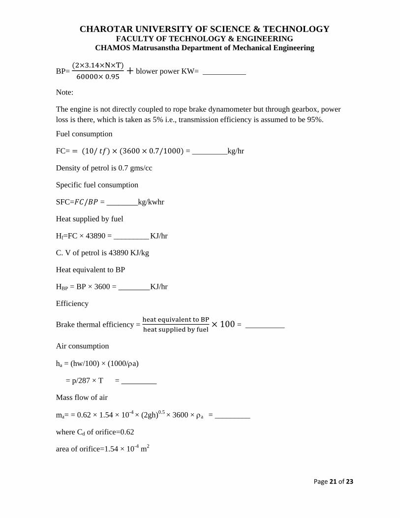
CALCULATION:
Brake power
BP=
= ________ KW
Note: practically dynamometer efficiency also varies with load and for each load, different
efficiency has to be taken from dynamometer efficiency curve, but for to avoid compilations,
same efficiency is assumed.
Field coil is also energized from armature, which consumes 0.198 kw at 220 volts. Hence, the
load is added to alternator with voltage correction factor.
For the tests conducts on the blower a the factory, it is observed that blower consumes power
of 0.5 kw at 3000 rpm
Fuel consumption
FC = _________kg/hr
Density of petrol is 0.7 gms/cc
Specific fuel consumption
SFC= =________kg/kwhr
Heat supplied by fuel
Hf= =________ KJ/hr
C. V of petrol is 43890 KJ/kg
Heat equivalent to BP
HBP = BP 3600= ________ KJ/hr
Efficiency
Brake thermal efficiency =
= __________
Air consumption
ha = hw (1000/a)
= p/287 × T = _________
Mass flow of air
ma= 0.62 × 1.54 × 10-4
× (2gh)0.5
× 3600 × a = _________
CHAROTAR UNIVERSITY OF SCIENCE & TECHNOLOGY
FACULTY OF TECHNOLOGY & ENGINEERING
CHAMOS Matrusanstha Department of Mechanical Engineering
Page 18 of 23
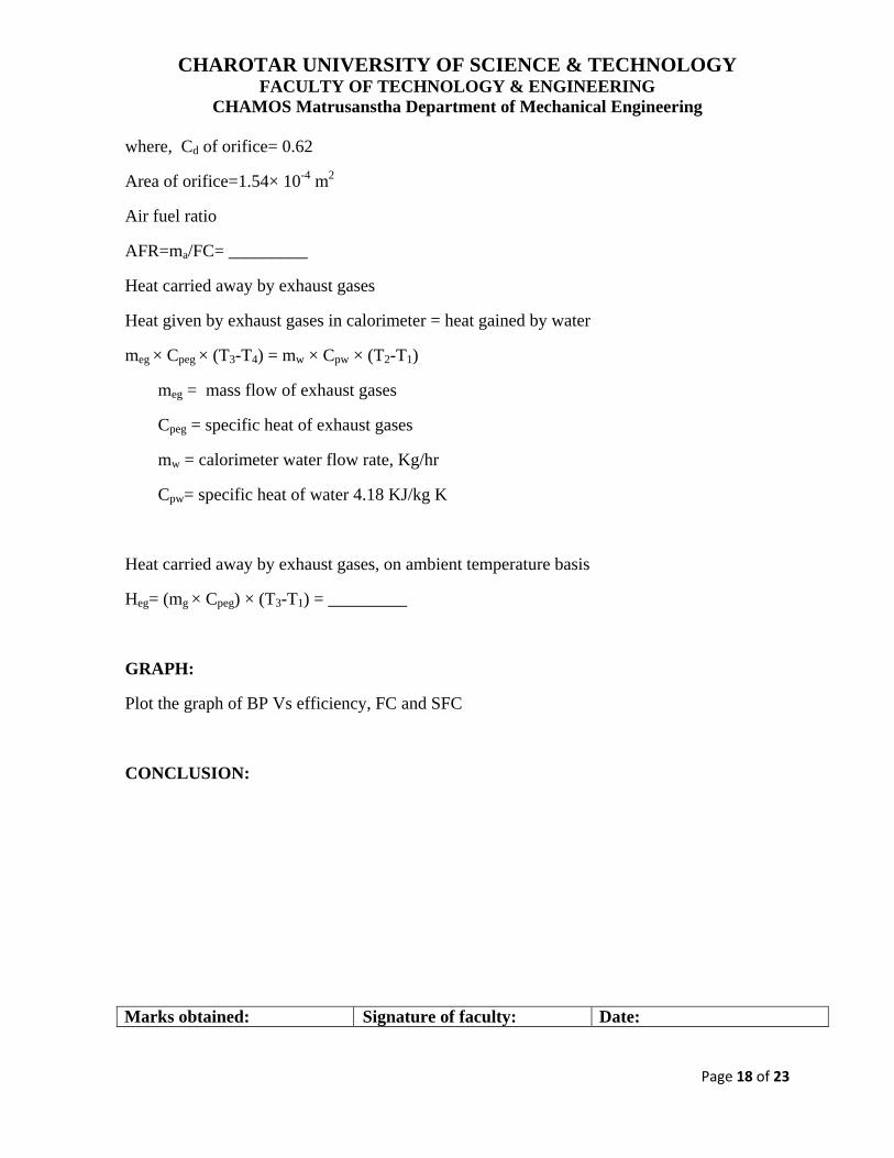
where, Cd of orifice= 0.62
Area of orifice=1.54× 10⁻⁴
m2
Air fuel ratio
AFR=ma/FC= _________
Heat carried away by exhaust gases
Heat given by exhaust gases in calorimeter = heat gained by water
meg × Cpeg × (T3-T4) = mw × Cpw × (T2-T1)
meg = mass flow of exhaust gases
Cpeg = specific heat of exhaust gases
mw = calorimeter water flow rate, Kg/hr
Cpw= specific heat of water 4.18 KJ/kg K
Heat carried away by exhaust gases, on ambient temperature basis
Heg= (mg × Cpeg) × (T3-T1) = _________
GRAPH:
Plot the graph of BP Vs efficiency, FC and SFC
CONCLUSION:
Marks obtained: Signature of faculty: Date:
CHAROTAR UNIVERSITY OF SCIENCE & TECHNOLOGY
FACULTY OF TECHNOLOGY & ENGINEERING
CHAMOS Matrusanstha Department of Mechanical Engineering
Page 19 of 23
Internal Combustion Engine (M-709) Date:
PRACTICAL NO 9
SINGLE CYLINDER TWO STROKE PETROL ENGINE
AIM: Performance test on two-stroke single-cylinder petrol engine with rope brake
dynamometer
OBJECTIVE:
To perform test on two-stroke single cylinder petrol engine with rope brake
dynamometer to understand its operational characteristics.
SPECIFICATIONS:
Make: Bajaj
Type: two stroke single cylinder horizontal petrol engine
Power: 4.5 HP
Speed: 6000 rpm
PRECAUTIONS:
Check water supply and crankcase oil level before starting the engine.
2% 2T oil must be added to petrol
Never stop the engine on load
From first 30 hrs of engine operation do not increase engine speed above 3000 rpm
PROCEDURE:
Fill up sufficient petrol in tank with 2% self mixing 2T oil
Check oil level in the gearbox of the engine. If necessary add up SAE-40 oil. Oil level
should be up to the oil-filling hole.
Confirm that the engine is in neutral gear and ignition switch in ON
Start water supply to calorimeter and brake drum
Pull the choke knob and give a sharp kick, engine will start. As the engine starts,
release the choke knob, pull the clutch and put the engine in 4th
gear
Slowly increase the accelerator and set the engine speed to say 2500 rpm
Put load on the engine.
Abhishek D S
Typewriter
(ME417)
Abhishek D S
Highlight
CHAROTAR UNIVERSITY OF SCIENCE & TECHNOLOGY
FACULTY OF TECHNOLOGY & ENGINEERING
CHAMOS Matrusanstha Department of Mechanical Engineering
Page 20 of 23
Fill the burette with burette filling cock. Note down time for 10ml fuel consumption,
manometer difference, spring balance difference, calorimeter water flow rate and
brake drum speed.
Note down and temperatures from T1 to T4
Increase the load by twisting the loading screw. Keep the speed constant with the help
of accelerator
Repeat the procedure for the different loads
Now keep accelerator position constant and go on increasing the load and note down