37
semester + www.semesterplus.com semester + www.semesterplus.com ME6404 THERMAL ENGINEERING UNIT III NOZZLES, TURBINES & STEAM POWER CYCLES
semester+
www.semesterplus.comsemester+
www.semesterplus.com
UNIT-III 3. 1
ME6404 THERMAL ENGINEERING
UNIT III
NOZZLES, TURBINES & STEAM POWER
CYCLES
semester+
www.semesterplus.comsemester+
www.semesterplus.com
UNIT-III 3. 2
CONTENTS
3.1 Flow of steam through nozzles:
3.2 Continuity and steady flow energy equations
3.3 Types of Nozzles
3.3.1 Convergent Nozzle
3.3.2 Divergent Nozzle
3.3.4 Convergent-Divergent Nozzle
3.4 Supersaturated flow or Meta stable flow in Nozzles
3.5 Mass of steam discharged through nozzle
3.6 Steam Turbines
3.6.1 Impulse Turbines
3.6.2 Reaction Turbines
3.7 Compounding of impulse turbine
3.7.1. Velocity Compounding
3.7. 2. Pressure Compounding
3.7. 3. Pressure-Velocity Compounding
3.8 Velocity diagram of an impulse turbine
3.9 Velocity diagram of the velocity compounded turbines
3.10 Governing of Steam Turbine
3.10.1. Throttle Governing
3.10.2. Nozzle Governing
3.11 Solved Problems
3.12 Two Marks University Questions
3.13 University Essay Questions
semester+
www.semesterplus.comsemester+
www.semesterplus.com
UNIT-III 3. 3
TECHNICAL TERMS:
1. Wet steam: The steam which contains some water particles in superposition.
2. Dry steam / dry saturated steam:
When whole mass of steam is converted into steam then it is called as dry steam.
3. Super heated steam: When the dry steam is further heated at constant pressure, the
temperature increases the above saturation temperature. The steam has obtained is called
super heated steam.
4. Degree of super heat: The difference between the temperature of saturated steam and
saturated temperature is called degree of superheat.
5. Nozzle:It is a duct of varying cross sectional area in which the velocity increases with the
corresponding drop in pressure.
6. Coefficient of nozzle: It is the ratio of actual enthalpy drop to isentropic enthalpy drop.
7. Critical pressure ratio: There is only one value of ratio (P2/P1) which produces
maximum discharge from the nozzle . then the ratio is called critical pressure ratio.
8. Degree of reaction: It is defined as the ratio of isentropic heat drop in the moving blade
to isentrpic heat drop in the entire stages of the reaction turbine.
9. Compounding: It is the method of absorbing the jet velocity in stages when the steam
flows over moving blades. (i)Velocity compounding (ii)Pressure compounding and (iii)
Velocity-pressure compounding
10. Enthalpy: It is the combination of the internal energy and the flow energy.
11. Entropy: It is the function of quantity of heat with respective to the temperature.
12. Convergent nozzle: The crossectional area of the duct decreases from inlet to the outlet
side then it is called as convergent nozzle.
semester+
www.semesterplus.comsemester+
www.semesterplus.com
UNIT-III 3. 4
13. Divergent nozzle: The crossectional area of the duct increases from inlet to the outlet
then it is called as divergent nozzle.
semester+
www.semesterplus.comsemester+
www.semesterplus.com
UNIT-III 3. 5
UNIT-III
NOZZLES, TURBINES & STEAM POWER CYCLES
3.1 Flow of steam through nozzles:
The flow of steam through nozzles may be regarded as adiabatic expansion. - The steam
has a very high velocity at the end of the expansion, and the enthalpy decreases as expansion
takes place. - Friction exists between the steam and the sides of the nozzle; heat is produced as
the result of the resistance to the flow. - The phenomenon of super saturation occurs in the flow
of steam through nozzles. This is due to the time lag in the condensation of the steam during the
expansion.
3.2 Continuity and steady flow energy equations
Through a certain section of the nozzle: m.v = A.C m is the mass flow rate, v is the
specific volume, A is the cross-sectional area and C is the velocity. For steady flow of steam
through a certain apparatus, principle of conservation of energy states:
h1 + C12 /2 + gz1 + q = h2 + C22 /2 + gz2 + w For nozzles, changes in potential energies are negligible, w = 0 and q ≅ 0. H1 + C12 /2 = h2 + C22 /2
3.3 Types of Nozzles:
1. Convergent Nozzle
2. Divergent Nozzle
3. Convergent-Divergent Nozzle
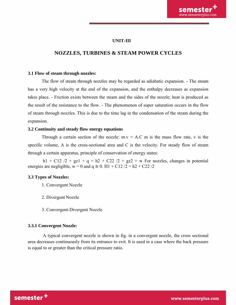
3.3.1 Convergent Nozzle:
A typical convergent nozzle is shown in fig. in a convergent nozzle, the cross sectional area decreases continuously from its entrance to exit. It is used in a case where the back pressure is equal to or greater than the critical pressure ratio.
semester+
www.semesterplus.comsemester+
www.semesterplus.com
UNIT-III 3. 6
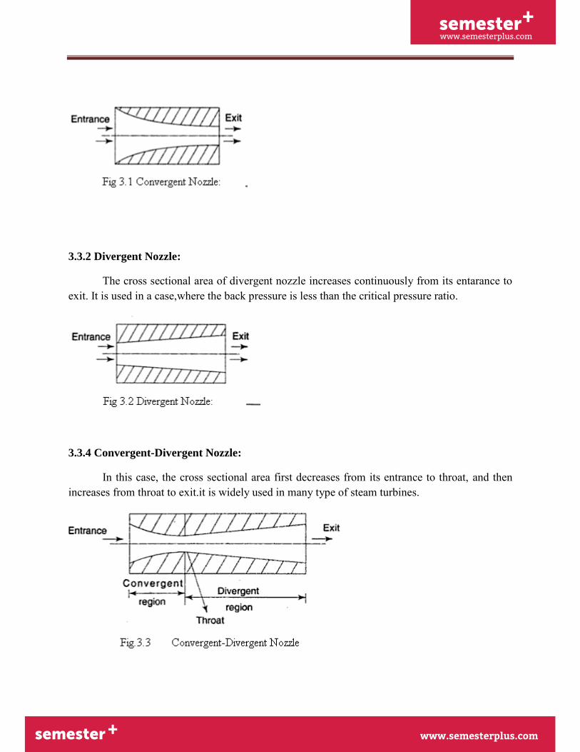
3.3.2 Divergent Nozzle:
The cross sectional area of divergent nozzle increases continuously from its entarance to exit. It is used in a case,where the back pressure is less than the critical pressure ratio.
3.3.4 Convergent-Divergent Nozzle:
In this case, the cross sectional area first decreases from its entrance to throat, and then increases from throat to exit.it is widely used in many type of steam turbines.
semester+
www.semesterplus.comsemester+
www.semesterplus.com
UNIT-III 3. 7
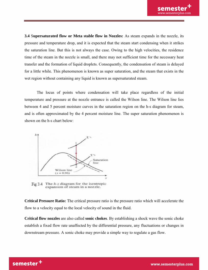
3.4 Supersaturated flow or Meta stable flow in Nozzles: As steam expands in the nozzle, its
pressure and temperature drop, and it is expected that the steam start condensing when it strikes
the saturation line. But this is not always the case. Owing to the high velocities, the residence
time of the steam in the nozzle is small, and there may not sufficient time for the necessary heat
transfer and the formation of liquid droplets. Consequently, the condensation of steam is delayed
for a little while. This phenomenon is known as super saturation, and the steam that exists in the
wet region without containing any liquid is known as supersaturated steam.
The locus of points where condensation will take place regardless of the initial
temperature and pressure at the nozzle entrance is called the Wilson line. The Wilson line lies
between 4 and 5 percent moisture curves in the saturation region on the h-s diagram for steam,
and is often approximated by the 4 percent moisture line. The super saturation phenomenon is
shown on the h-s chart below:
Critical Pressure Ratio: The critical pressure ratio is the pressure ratio which will accelerate the
flow to a velocity equal to the local velocity of sound in the fluid.
Critical flow nozzles are also called sonic chokes. By establishing a shock wave the sonic choke
establish a fixed flow rate unaffected by the differential pressure, any fluctuations or changes in
downstream pressure. A sonic choke may provide a simple way to regulate a gas flow.

semester+
www.semesterplus.comsemester+
www.semesterplus.com
UNIT-III 3. 8
The ratio between the critical pressure and the initial pressure for a nozzle can expressed as
Pc / p1 = (2 / (n + 1)) n / (n – 1)
Where, pc = critical pressure (Pa)
p1 = inlet pressure (Pa)
n = index of isentropic expansion or compression – or polytrophic constant
For a perfect gas undergoing an adiabatic process the index – n – is the ratio of specific heats
k = cp / cv. There is no unique value for – n. Values for some common gases are
Steam where most of the process occurs in the wet region: n = 1.135
Steam super-heated: n = 1.30
Air: n = 1.4
Methane: n = 1.31
Helium: n = 1.667
Effect of Friction on Nozzles:
1) Entropy is increased.
2) Available energy is decreased.
3) Velocity of flow at throat is decreased.
4) Volume of flowing steam is decreased.
5) Throat area necessary to discharge a given mass of steam is increased.
semester+
www.semesterplus.comsemester+
www.semesterplus.com
UNIT-III 3. 9
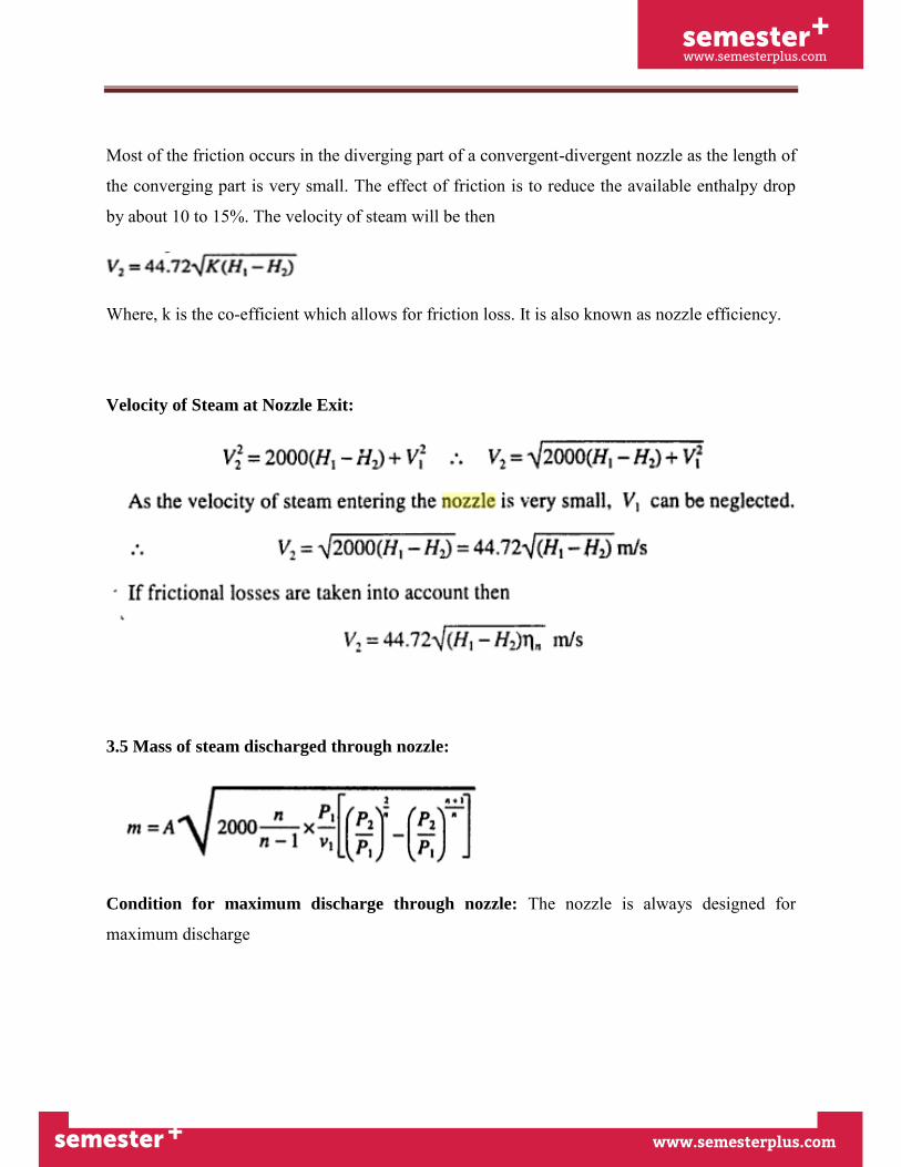
Most of the friction occurs in the diverging part of a convergent-divergent nozzle as the length of
the converging part is very small. The effect of friction is to reduce the available enthalpy drop
by about 10 to 15%. The velocity of steam will be then
Where, k is the co-efficient which allows for friction loss. It is also known as nozzle efficiency.
Velocity of Steam at Nozzle Exit:
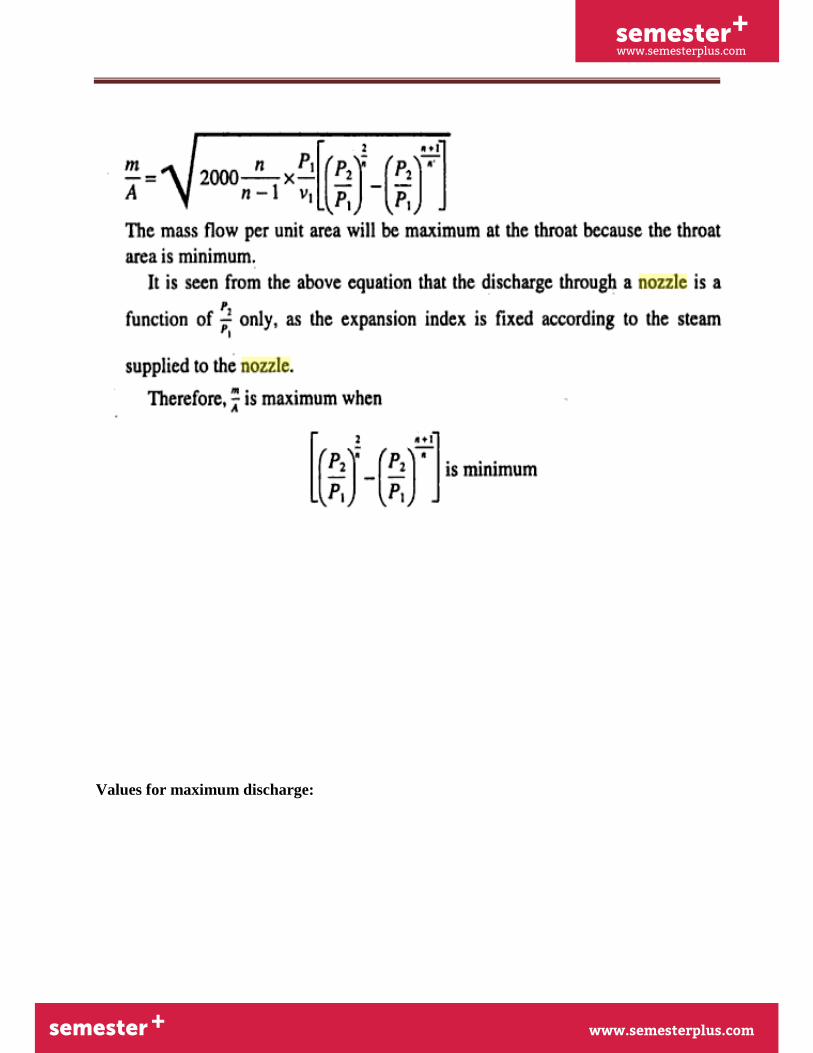
3.5 Mass of steam discharged through nozzle:
Condition for maximum discharge through nozzle: The nozzle is always designed for
maximum discharge
semester+
www.semesterplus.comsemester+
www.semesterplus.com
UNIT-III 3. 10
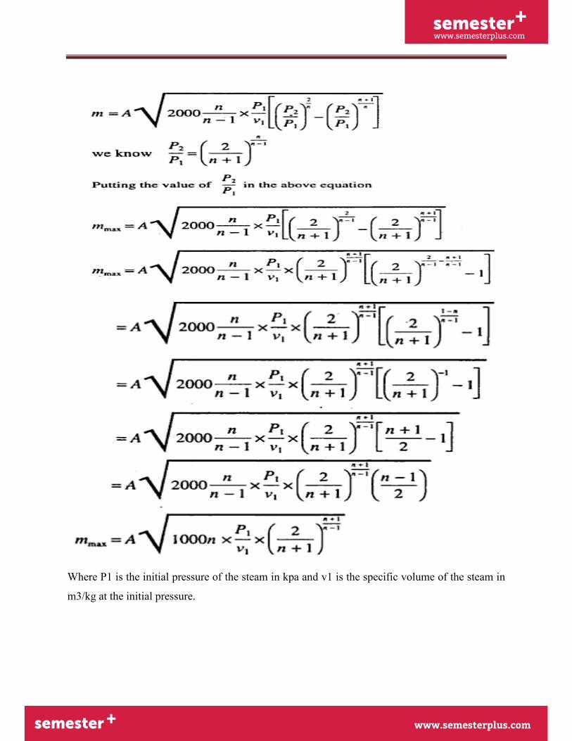
Values for maximum discharge:
semester+
www.semesterplus.comsemester+
www.semesterplus.com
UNIT-III 3. 11
Where P1 is the initial pressure of the steam in kpa and v1 is the specific volume of the steam in
m3/kg at the initial pressure.
semester+
www.semesterplus.comsemester+
www.semesterplus.com
UNIT-III 3. 12
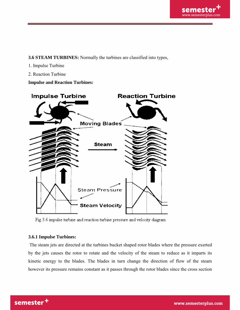
3.6 STEAM TURBINES: Normally the turbines are classified into types,
1. Impulse Turbine
2. Reaction Turbine
Impulse and Reaction Turbines:
3.6.1 Impulse Turbines:
The steam jets are directed at the turbines bucket shaped rotor blades where the pressure exerted
by the jets causes the rotor to rotate and the velocity of the steam to reduce as it imparts its
kinetic energy to the blades. The blades in turn change the direction of flow of the steam
however its pressure remains constant as it passes through the rotor blades since the cross section
semester+
www.semesterplus.comsemester+
www.semesterplus.com
UNIT-III 3. 13
of the chamber between the blades is constant. Impulse turbines are therefore also known as
constant pressure turbines. The next series of fixed blades reverses the direction of the steam
before it passes to the second row of moving blades.
3.6.2 Reaction Turbines
The rotor blades of the reaction turbine are shaped more like aero foils, arranged such that the
cross section of the chambers formed between the fixed blades diminishes from the inlet side
towards the exhaust side of the blades. The chambers between the rotor blades essentially form
nozzles so that as the steam progresses through the chambers its velocity increases while at the
same time its pressure decreases, just as in the nozzles formed by the fixed blades. Thus the
pressure decreases in both the fixed and moving blades. As the steam emerges in a jet from
between the rotor blades, it creates a reactive force on the blades which in turn creates the
turning moment on the turbine rotor, just as in Hero’s steam engine. (Newton’s Third Law – For
every action there is an equal and opposite reaction).
3.7 Compounding of impulse turbine:
- This is done to reduce the rotational speed of the impulse turbine to practical limits. (A rotor
speed of 30,000 rpm is possible, which is pretty high for practical uses.) - Compounding is
achieved by using more than one set of nozzles, blades, rotors, in a series, keyed to a common
shaft; so that either the steam pressure or the jet velocity is absorbed by the turbine in stages. -
Three main types of compounded impulse turbines are: a) Pressure compounded, b) velocity
compounded and c) pressure and velocity compounded impulse turbines.
3.7.1. Velocity Compounding:
semester+
www.semesterplus.comsemester+
www.semesterplus.com
UNIT-III 3. 14
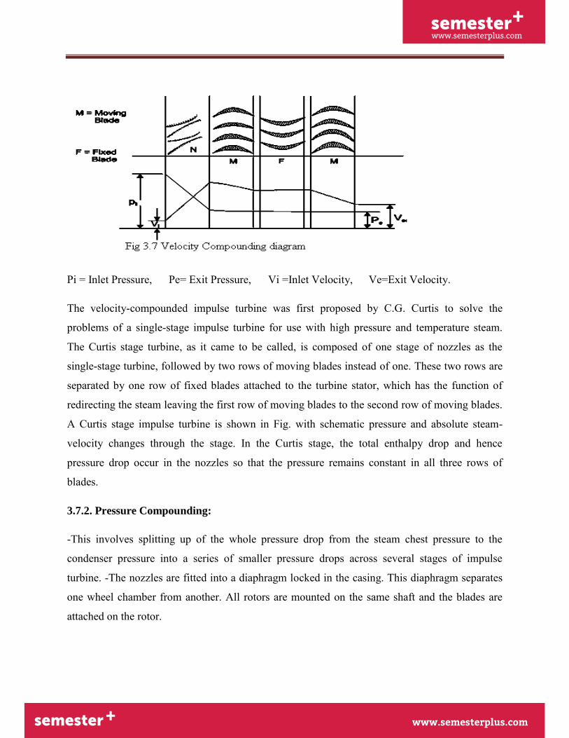
Pi = Inlet Pressure, Pe= Exit Pressure, Vi =Inlet Velocity, Ve=Exit Velocity.
The velocity-compounded impulse turbine was first proposed by C.G. Curtis to solve the
problems of a single-stage impulse turbine for use with high pressure and temperature steam.
The Curtis stage turbine, as it came to be called, is composed of one stage of nozzles as the
single-stage turbine, followed by two rows of moving blades instead of one. These two rows are
separated by one row of fixed blades attached to the turbine stator, which has the function of
redirecting the steam leaving the first row of moving blades to the second row of moving blades.
A Curtis stage impulse turbine is shown in Fig. with schematic pressure and absolute steam-
velocity changes through the stage. In the Curtis stage, the total enthalpy drop and hence
pressure drop occur in the nozzles so that the pressure remains constant in all three rows of
blades.
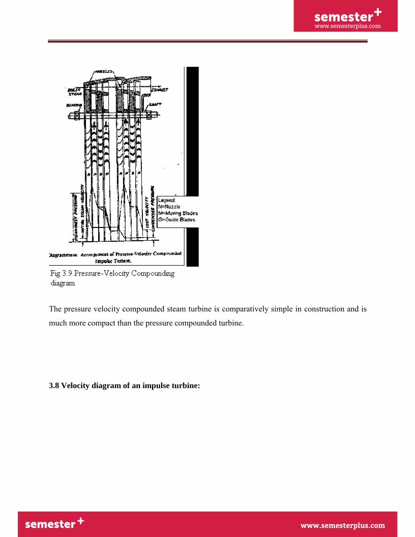
3.7.2. Pressure Compounding:
-This involves splitting up of the whole pressure drop from the steam chest pressure to the
condenser pressure into a series of smaller pressure drops across several stages of impulse
turbine. -The nozzles are fitted into a diaphragm locked in the casing. This diaphragm separates
one wheel chamber from another. All rotors are mounted on the same shaft and the blades are
attached on the rotor.

semester+
www.semesterplus.comsemester+
www.semesterplus.com
UNIT-III 3. 15
3.7.3. Pressure-Velocity Compounding
This is a combination of pressure and velocity compounding. A two-row velocity compounded
turbine is found to be more efficient than the three-row type. In a two-step pressure velocity
compounded turbine, the first pressure drop occurs in the first set of nozzles, the resulting gain in
the kinetic energy is absorbed successively in two rows of moving blades before the second
pressure drop occurs in the second set of nozzles. Since the kinetic energy gained in each step is
absorbed completely before the next pressure drop, the turbine is pressure compounded and as
well as velocity compounded. The kinetic energy gained due to the second pressure drop in the
second set of nozzles is absorbed successively in the two rows of moving blades.
semester+
www.semesterplus.comsemester+
www.semesterplus.com
UNIT-III 3. 16
The pressure velocity compounded steam turbine is comparatively simple in construction and is
much more compact than the pressure compounded turbine.
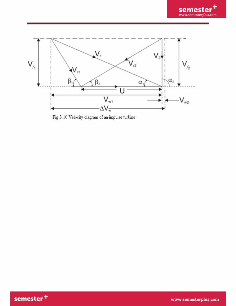
3.8 Velocity diagram of an impulse turbine:
semester+
www.semesterplus.comsemester+
www.semesterplus.com
UNIT-III 3. 17
semester+
www.semesterplus.comsemester+
www.semesterplus.com
UNIT-III 3. 18
semester+
www.semesterplus.comsemester+
www.semesterplus.com
UNIT-III 3. 19
semester+
www.semesterplus.comsemester+
www.semesterplus.com
UNIT-III 3. 20
semester+
www.semesterplus.comsemester+
www.semesterplus.com
UNIT-III 3. 21
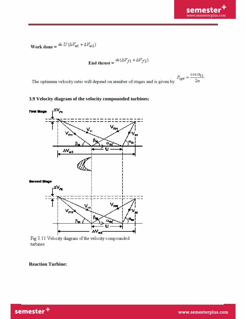
3.9 Velocity diagram of the velocity compounded turbines:
Reaction Turbine:
semester+
www.semesterplus.comsemester+
www.semesterplus.com
UNIT-III 3. 22
A reaction turbine, therefore, is one that is constructed of rows of fixed and rows of moving
blades. The fixed blades act as nozzles. The moving blades move as a result of the impulse of
steam received (caused by change in momentum) and also as a result of expansion and
acceleration of the steam relative to them. In other words, they also act as nozzles. The enthalpy
drop per stage of one row fixed and one row moving blades is divided among them, often
equally. Thus a blade with a 50 percent degree of reaction, or a 50 percent reaction stage, is one
in which half the enthalpy drop of the stage occurs in the fixed blades and half in the moving
blades. The pressure drops will not be equal, however. They are greater for the fixed blades and
greater for the high-pressure than the low-pressure stages. The moving blades of a reaction
turbine are easily distinguishable from those of an impulse turbine in that they are not
symmetrical and, because they act partly as nozzles, have a shape similar to that of the fixed
blades, although curved in the opposite direction. The schematic pressure line in figure shows
that pressure continuously drops through all rows of blades, fixed and moving. The absolute
steam velocity changes within each stage as shown and repeats from stage to stage. The second
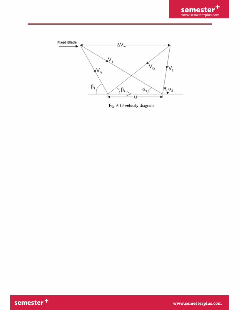
figure shows a typical velocity diagram for the reaction stage.
semester+
www.semesterplus.comsemester+
www.semesterplus.com
UNIT-III 3. 23
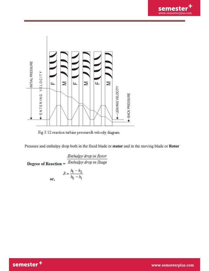
Pressure and enthalpy drop both in the fixed blade or stator and in the moving blade or Rotor
semester+
www.semesterplus.comsemester+
www.semesterplus.com
UNIT-III 3. 24
semester+
www.semesterplus.comsemester+
www.semesterplus.com
UNIT-III 3. 25
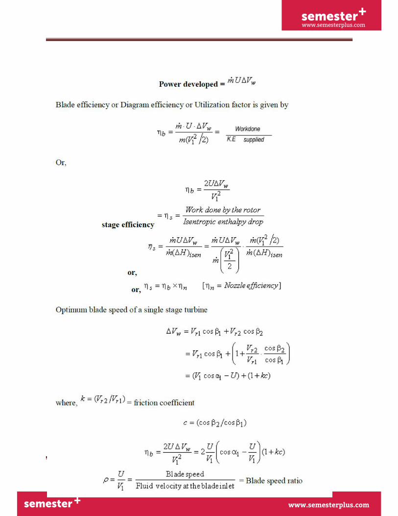
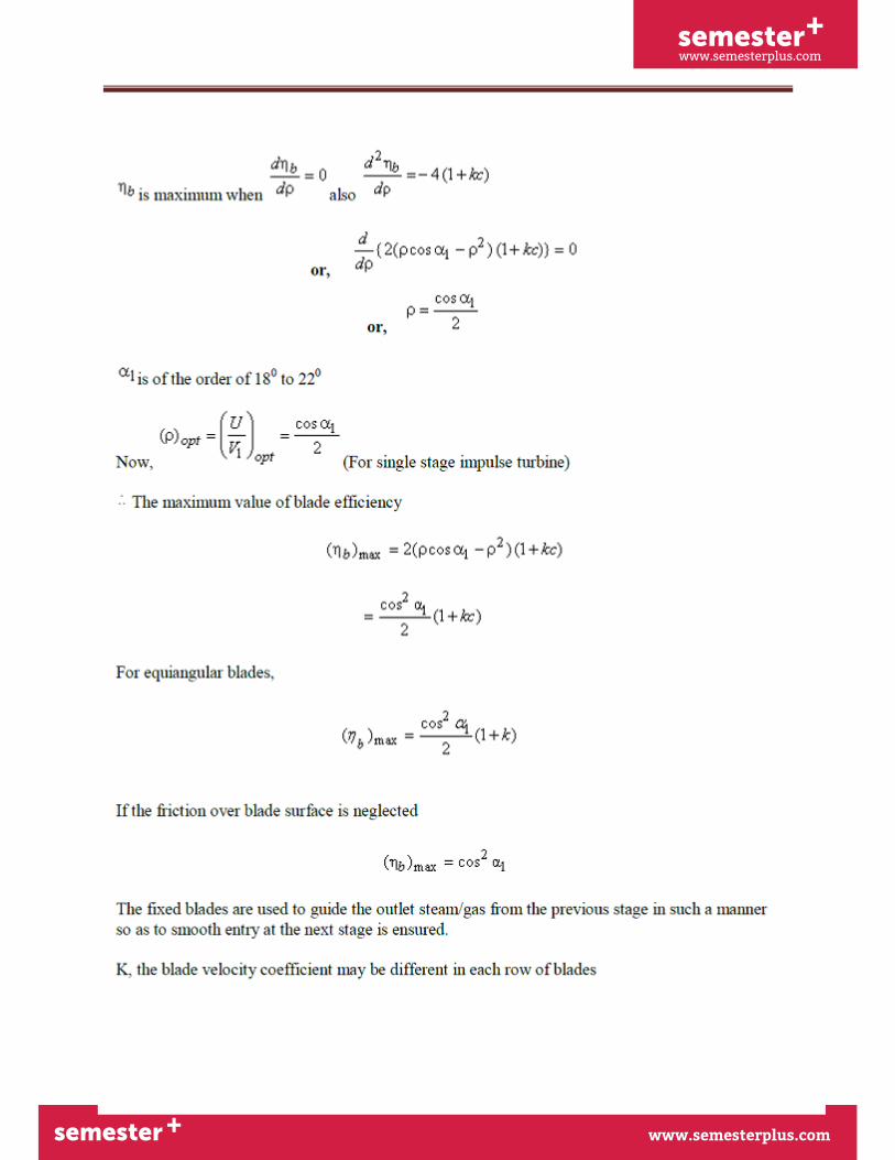
Therefore, the blade efficiency

semester+
www.semesterplus.comsemester+
www.semesterplus.com
UNIT-III 3. 26
3.10 Governing of Steam Turbine: The method of maintaining the turbine speed constant
irrespective of the load is known as governing of turbines. The device used for governing of
turbines is called Governor. There are 3 types of governors in steam turbine,
1. Throttle governing
2. Nozzle governing
3. By-pass governing
3.10.1. Throttle Governing:
Let us consider an instant when the load on the turbine increases, as a result the speed of the
turbine decreases. The fly balls of the governor will come down. The fly balls bring down the
sleeve. The downward movement of the sleeve will raise the control valve rod. The mouth of the
pipe AA will open. Now the oil under pressure will rush from the control valve to right side of
piston in the rely cylinder through the pipe AA. This will move the piston and spear towards the
semester+
www.semesterplus.comsemester+
www.semesterplus.com
UNIT-III 3. 27
left which will open more area of nozzle. As a result steam flow rate into the turbine increases,
which in turn brings the speed of the turbine to the normal range.
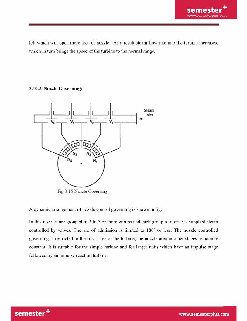
3.10.2. Nozzle Governing:
A dynamic arrangement of nozzle control governing is shown in fig.
In this nozzles are grouped in 3 to 5 or more groups and each group of nozzle is supplied steam
controlled by valves. The arc of admission is limited to 180º or less. The nozzle controlled
governing is restricted to the first stage of the turbine, the nozzle area in other stages remaining
constant. It is suitable for the simple turbine and for larger units which have an impulse stage
followed by an impulse reaction turbine.
semester+
www.semesterplus.comsemester+
www.semesterplus.com
UNIT-III 3. 28
3.11 Solved Problems:
1. A convergent divergent adiabatic steam nozzle is supplied with steam at 10 bar and 250°c.the
discharge pressure is 1.2 bar.assuming that the nozzle efficiency is 100% and initial velocity of
steam is 50 m/s. find the discharge velocity.
Given Data:-
Initial pressure(p1)=10bar
Initial temperature(T1)=250°c
Exit pressure(p2)=1.2 bar
Nozzle efficiency(ηnozzle)=100%
Initial velocity of steam(v1)=50m/s
To Find:-
Discharge velocity (v2)
Solution:-
From steam table, For 10 bar, 250°c,
h1=2943 KJ/kg
s1=6.926 KJ/kgk
From steam table, For 1.2 bar,
semester+
www.semesterplus.comsemester+
www.semesterplus.com
UNIT-III 3. 29
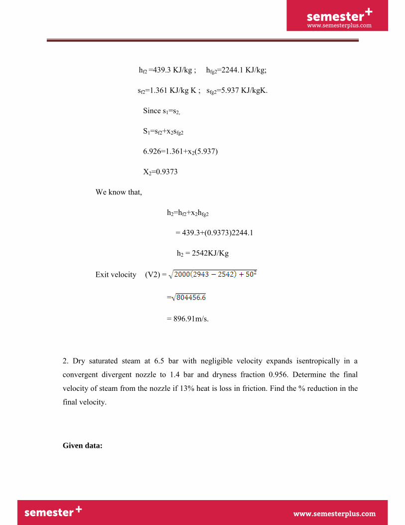
hf2 =439.3 KJ/kg ; hfg2=2244.1 KJ/kg;
sf2=1.361 KJ/kg K ; sfg2=5.937 KJ/kgK.
Since s1=s2,
S1=sf2+x2sfg2
6.926=1.361+x2(5.937)
X2=0.9373
We know that,
h2=hf2+x2hfg2
= 439.3+(0.9373)2244.1
h2 = 2542KJ/Kg
Exit velocity (V2) =
=
= 896.91m/s.
2. Dry saturated steam at 6.5 bar with negligible velocity expands isentropically in a
convergent divergent nozzle to 1.4 bar and dryness fraction 0.956. Determine the final
velocity of steam from the nozzle if 13% heat is loss in friction. Find the % reduction in the
final velocity.
Given data:
semester+
www.semesterplus.comsemester+
www.semesterplus.com
UNIT-III 3. 30
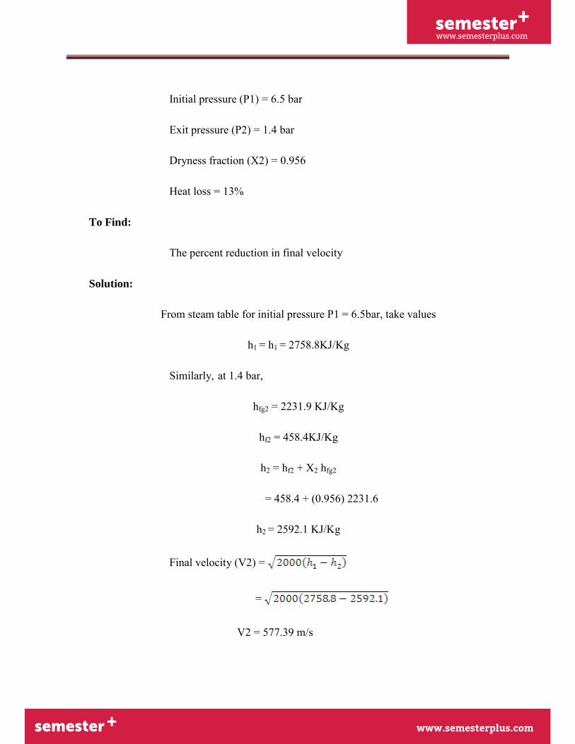
Initial pressure (P1) = 6.5 bar
Exit pressure (P2) = 1.4 bar
Dryness fraction (X2) = 0.956
Heat loss = 13%
To Find:
The percent reduction in final velocity
Solution:
From steam table for initial pressure P1 = 6.5bar, take values
h1 = h1 = 2758.8KJ/Kg
Similarly, at 1.4 bar,
hfg2 = 2231.9 KJ/Kg
hf2 = 458.4KJ/Kg
h2 = hf2 + X2 hfg2
= 458.4 + (0.956) 2231.6
h2 = 2592.1 KJ/Kg
Final velocity (V2) =
=
V2 = 577.39 m/s
semester+
www.semesterplus.comsemester+
www.semesterplus.com
UNIT-III 3. 31
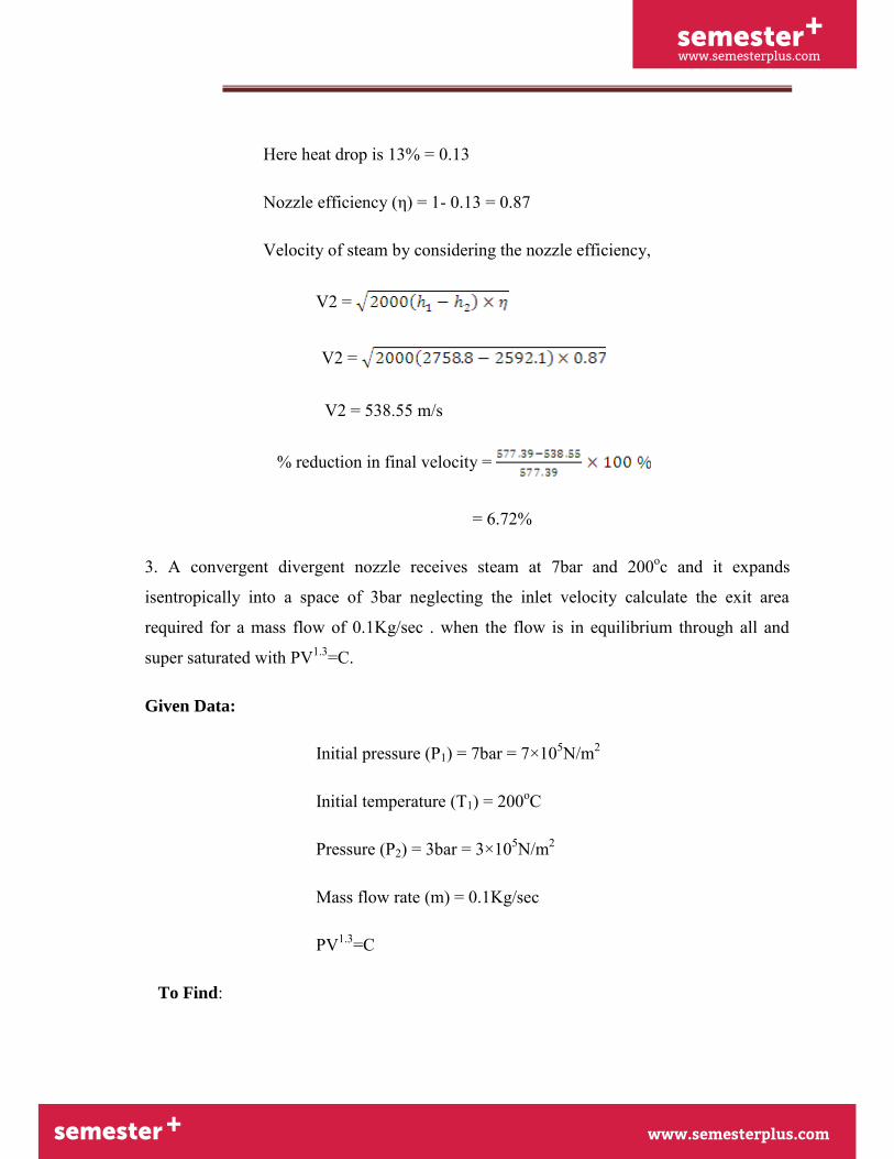
Here heat drop is 13% = 0.13
Nozzle efficiency (η) = 1- 0.13 = 0.87
Velocity of steam by considering the nozzle efficiency,
V2 =
V2 =
V2 = 538.55 m/s
% reduction in final velocity =
= 6.72%
3. A convergent divergent nozzle receives steam at 7bar and 200oc and it expands
isentropically into a space of 3bar neglecting the inlet velocity calculate the exit area
required for a mass flow of 0.1Kg/sec . when the flow is in equilibrium through all and
super saturated with PV1.3=C.
Given Data:
Initial pressure (P1) = 7bar = 7×10⁵N/m2
Initial temperature (T1) = 200oC
Pressure (P2) = 3bar = 3×10⁵N/m2
Mass flow rate (m) = 0.1Kg/sec
PV1.3=C
To Find:
semester+
www.semesterplus.comsemester+
www.semesterplus.com
UNIT-III 3. 32
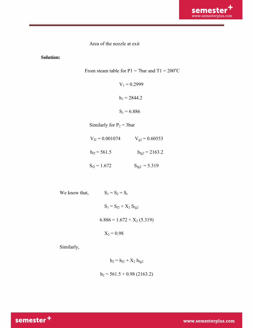
Area of the nozzle at exit
Solution:
From steam table for P1 = 7bar and T1 = 200oC
V1 = 0.2999
h1 = 2844.2
S1 = 6.886
Similarly for P2 = 3bar
Vf2 = 0.001074 Vg2 = 0.60553
hf2 = 561.5 hfg2 = 2163.2
Sf2 = 1.672 Sfg2 = 5.319
We know that, S1 = S2 = St
S1 = Sf2 + X2 Sfg2
6.886 = 1.672 + X2 (5.319)
X2 = 0.98
Similarly,
h2 = hf2 + X2 hfg2
h2 = 561.5 + 0.98 (2163.2)
semester+
www.semesterplus.comsemester+
www.semesterplus.com
UNIT-III 3. 33
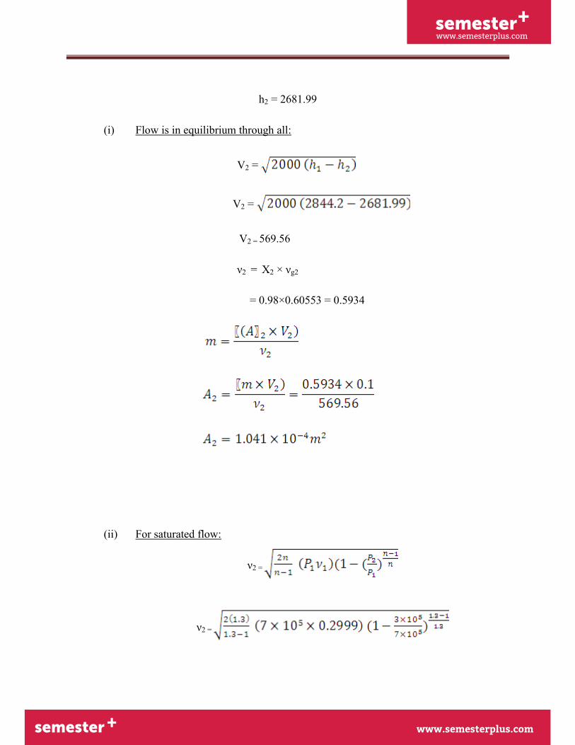
h2 = 2681.99
(i) Flow is in equilibrium through all:
V2 =
V2 =
V2 = 569.56
ν2 = X2 × νg2
= 0.98×0.60553 = 0.5934
(ii) For saturated flow:
ν2 =
ν2 =
semester+
www.semesterplus.comsemester+
www.semesterplus.com
UNIT-III 3. 34
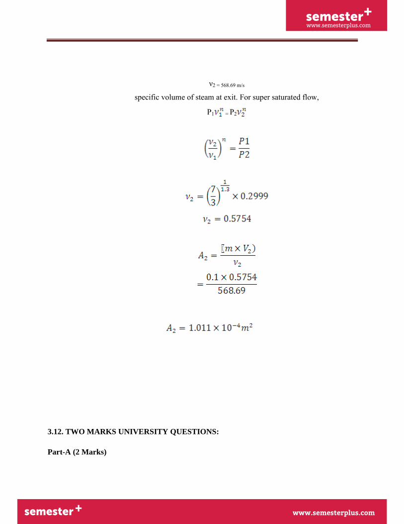
ν2 = 568.69 m/s
specific volume of steam at exit. For super saturated flow,
P1 = P2
3.12. TWO MARKS UNIVERSITY QUESTIONS:
Part-A (2 Marks)
semester+
www.semesterplus.comsemester+
www.semesterplus.com
UNIT-III 3. 35
1. What are the various types of nozzles and their functions?
2. Define nozzle efficiency and critical pressure ratio.
3. Explain the phenomenon of super saturated expansion in steam nozzle. Or what is metastable
flow?
4. State the function of fixed blades.
5. Classify steam turbines.
6. How does impulse work?
7. What is meant by carry over loss?
8. State the function of moving blades...."
9. What is the fundamental difference between the operation of impulse and reaction steam
turbines?
10. What are the different methods of governing steam turbines?
11. How is throttle governing done?
12. Where nozzle control governing is used?
13. Whereby - pass governing is more suitable?
14. What are the different losses in steam turbines?
semester+
www.semesterplus.comsemester+
www.semesterplus.com
UNIT-III 3. 36
2.13. UNIVERSITY ESSAY QUESTIONS:
PART- B (16Marks)
1. An impulse turbine having a set of 16 nozzles receives steam at 20 bar, 400° C. The pressure
of steam at exist is 12 bar. if the total discharge Is 260 Kg/min and nozzle efficiency is 90% .
Find the cross sectional area of each nozzle, if the steam has velocity of 80m/s at entry to the
nozzle, find the percentage Increase In discharge. (16)
2. Dry saturated steam at a pressure of 8 bar enters the convergent divergent nozzle and leaves it
at a pressure 1.5 bar. If the flow isentropic and if the corresponding index of expansion is
1.133, find the ratio of 0.3 are at exit and throat for max. discharge. (16)
3. Steam enters a group of nozzles of a steam turbine at 12 bar and 2200 C and leaves at 1.2 bar.
The steam turbine develops 220 Kw with a specific steam consumption of 13.5 Kg/ Kw. Hr. If
the diameter of nozzle at throat Is 7mm . Calculate the number of nozzle (16)
4. Drive an expression for critical pressure ratio in terms of the index of expansion (16)
5. Explain the method of governing in steam turbine. (16)
6. Explain various type of compounding in Turbine (16)
7. A 50% reaction turbine running at 400 rpm has the exit angle of blades as 20° and the velocity
of steam relative to the blade at the exit is 1.35 times mean speed of the blade. The steam flow
rate is 8.33 kg/s and at a particular stage the specific volume is 1.38m3/kg .Calculate, suitable
blade height, assuming the rotor mean diameter 12 times the blade height, and diagram work.
(16)
8. The blade angle of a single ring of an impulse turbine is 300m/s and the nozzle angle is
200.The isentropic heat drop is 473kJ/kg and nozzle efficiency is 85%.Given the blade
velocity coefficient is 0.7 and the blades are symmetrical, Draw the velocity diagram and
semester+
www.semesterplus.comsemester+
www.semesterplus.com
UNIT-III 3. 37
calculate for a mass flow of 1 kg/s i) axial thrust on balding ii) steam consumption per BP
hour if the mechanical efficiency is 90% iii) blade efficiency and stage efficiency. (16)


