This Measure Guideline describes a deep energy enclosure retrofit (DEER) solution that provides insulation to the interior of the wall assembly with the use of a double stud wall. The guide describes two approaches to retrofitting the existing the walls: one involving replacement of the existing cladding, and the other that leaves the existing cladding in place. It discusses the design principles related to the use of various insulation types, and provides strategies and procedures for implementing the double stud wall retrofit. It also evaluates important moisture-related and indoor air quality measures that need to be implemented to achieve a durable, high performancewall.
This Measure Guideline is intended to support contractors implementing an interior insulation high performance enclosure retrofit, and designers looking to design such retrofits. The Measure Guideline can also inform building owners on strategies available for deep energy enclosure retrofits of wood-framed residential buildings.
This Measure Guideline is important to the high performance retrofit industry because it demonstrates techniques for implementing double stud walls in high performance enclosure retrofits. The information included in the guide is based on the latest research performed for the Department of Energy (DOE) Building Ameri-ca program.
Deep Energy Enclosure Retrofit (DEER) for Double Stud Walls Building Science Corporation H. Loomis, B. Pettit
January 2015
NOTICE
This report was prepared as an account of work sponsored by an agency of the United States government. Neither the United States government nor any agency thereof, nor any of their employees, subcontractors, or affiliated partners makes any warranty, express or implied, or assumes any legal liability or responsibility for the accuracy, completeness, or usefulness of any information, apparatus, product, or process disclosed, or represents that its use would not infringe privately owned rights. Reference herein to any specific commercial product, process, or service by trade name, trademark, manufacturer, or otherwise does not necessarily constitute or imply its endorsement, recommendation, or favoring by the United States government or any agency thereof. The views and opinions of authors expressed herein do not necessarily state or reflect those of the United States government or any agency thereof.
Available electronically at http://www.osti.gov/scitech
Available for a processing fee to U.S. Department of Energy and its contractors, in paper, from:
U.S. Department of Energy Office of Scientific and Technical Information P.O. Box 62 Oak Ridge, TN 37831-0062 phone: 865.576.8401 fax: 865.576.5728 email: mailto:[email protected]
Available for sale to the public, in paper, from: U.S. Department of Commerce National Technical Information Service 5285 Port Royal Road Springfield, VA 22161 phone: 800.553.6847 fax: 703.605.6900 email: [email protected] online ordering: http://www.ntis.gov/help/ordermethods.aspx
Printed on paper containing at least 50% wastepaper, including 20% postconsumer waste
Deep Energy Enclosure Retrofit (DEER) for Double Stud Walls
Prepared for:
The National Renewable Energy Laboratory
On behalf of the U.S. Department of Energy’s Building America Program
Office of Energy Efficiency and Renewable Energy
15013 Denver West Parkway
Golden, CO 80401
NREL Contract No. DE-AC36-08GO28308
Prepared by:
H. Loomis, B. Pettit
Building Science Corporation
3 Lan Drive, Suite 102
Westford, MA 01886
NREL Technical Monitor: Stacey Rothgeb
Prepared under Subcontract No. KNDJ-0-40337-05
January 2015
[This page left blank]
Contents
List of Figures ............................................................................................................................................ iv List of Tables ............................................................................................................................................... v Definitions ................................................................................................................................................... vi Abstract ........................................................................................................................................................ 1 Progression Summary: Deep Energy Enclosure Retrofit for Double Stud Wall with New Cladding . 2 Progression Summary: Deep Energy Enclosure Retrofit for Double Stud Wall with Existing
Cost and Performance ................................................................................................................6 Water Leakage Management .....................................................................................................7 Air Leakage Management ..........................................................................................................7 Constructibility ..........................................................................................................................7
3 Technical Description .............................................................................................................................. 9 Double Stud Wall Assembly: Replace Cladding .......................................................................9 Double Stud Wall Assembly: Retain Cladding .......................................................................11 Water Control Layer ................................................................................................................13 Air Control Layer .....................................................................................................................15 Vapor Control Layer (Principles) ............................................................................................15 Vapor Control Layer (Assemblies) ..........................................................................................16 Thermal Control Layer ............................................................................................................18 Climate Zones and Building Environments .............................................................................18
4 Measure Implementation ....................................................................................................................... 22 New Cladding Option ..............................................................................................................22 Existing Cladding Option ........................................................................................................22 Climate Specific Factors ..........................................................................................................22 Field Inspection ........................................................................................................................22 Implementation Risks ..............................................................................................................23 Installation Procedure for New Cladding Option ....................................................................23
A. Remove existing wall cladding and trim; prepare wall sheathing for water and air control membrane ..................................................................................................23
B. Remove windows and doors as needed .........................................................................24 C. Install water and air control membrane .........................................................................24 D. Install flashings, air control transitions, windows and doors ........................................25 E. Install new wall cladding and trim ................................................................................26 F. Remove interior finishes ................................................................................................26 G. Install stud wall and cavity insulation ...........................................................................26 H. Install new gypsum board .............................................................................................27
Installation Procedure for Existing Cladding Option ...............................................................28 A. Retain existing wall cladding and trim .........................................................................28 B. Remove windows and doors as needed .........................................................................28 C. Install flashings, air control transitions, windows and doors ........................................28 D. Remove interior finishes ...............................................................................................28 E. Install stud wall and cavity insulation ...........................................................................28 F. Install new gypsum board ..............................................................................................28
Figure 1: New cladding approach - double stud wall with cellulose insulation ................................... 9 Figure 2: New cladding approach - double stud wall with ocSPF insulation ..................................... 10 Figure 3: New cladding approach - double stud wall with ccSPF and fibrous insulation ................. 10 Figure 4: Existing cladding approach - double stud wall with ocSPF insulation ............................... 12 Figure 5: Existing cladding approach - double stud wall with ccSPF and fibrous insulation .......... 12 Figure 6: The "down" and "out" approach to flashing (left); flashing integrated with the water
control layer with lapped joints (right) ............................................................................................. 13 Figure 7: Head and sill window detail at double stud wall with new cladding ................................... 14 Figure 8: Head and sill window detail at double stud wall with existing cladding ............................. 14 Figure 9: Department of Energy climate zones...................................................................................... 19 Figure 10: Hygrothermal map (Lstiburek, Joseph. (2006). Builder's Guide to Cold Climates.
Westford, MA: Building Science Press) ........................................................................................... 20 Figure 11: Rainfall map (Lstiburek, Joseph. (2006). Water Management Guide. Westford, MA:
Building Science Press) ..................................................................................................................... 21 Figure 12: Exterior finishes removed and existing wall sheathing is exposed .................................. 24 Figure 13: Windows and doors are removed ......................................................................................... 24 Figure 14: Water and air control membrane is in place ........................................................................ 25 Figure 15: Re-install existing windows or install new units ................................................................. 25 Figure 16: Completed cladding and trim ................................................................................................ 26 Figure 17: Interior finishes removed ....................................................................................................... 26 Figure 18: ccSPF and cellulose insulation ............................................................................................. 27 Figure 19: New gypsum board installed ................................................................................................. 27
List of Tables
Table 1. RS Means Unit Costs for Double Stud Wall Retrofit Components ($/sf) ................................ 6 Table 2. Vapor retarder classes (2009 IRC and 2012 IRC). ................................................................... 16 Table 3. Thermal resistance values to control condensation for climate zones 5, 6, 7, 8 and marine
4 from (2009 IRC and 2012 IRC). ....................................................................................................... 17 Table 4. Recommended Minimum R-Value for Wall Enclosures .......................................................... 18
Definitions
ADA Airtight Drywall Approach ccSPF Closed cell spray polyurethane foam DEER Deep Energy Enclosure Retrofit IBC International Building Code IECC International Energy Conservation Code IRC International Residential Code for One and Two Family Dwellings ocSPF Open cell spray polyurethane foam PIC Polyisocyanurate sf Square foot area SPF Spray-applied polyurethane foam XPS Extruded polystyrene
1
Abstract
This Measure Guideline describes a deep energy enclosure retrofit (DEER) solution that provides insulation to the interior of the wall assembly with the use of a double stud wall. The guide describes two approaches to retrofitting the existing the walls: one involving replacement of the existing cladding, and the other that leaves the existing cladding in place. It discusses the design principles related to the use of various insulation types, and provides strategies and procedures for implementing the double stud wall retrofit. It also evaluates important moisture-related and indoor air quality measures that need to be implemented to achieve a durable, high performance wall. This Measure Guideline is intended to support contractors implementing an interior insulation high performance enclosure retrofit, and designers looking to design such retrofits. The Measure Guideline can also inform building owners on strategies available for deep energy enclosure retrofits of wood-framed residential buildings. This Measure Guideline is important to the high performance retrofit industry because it demonstrates techniques for implementing double stud walls in high performance enclosure retrofits. The information included in the guide is based on the latest research performed for the Department of Energy (DOE) Building America program.
2
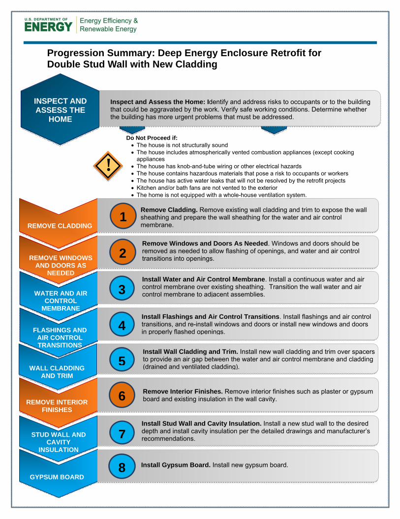
Progression Summary: Deep Energy Enclosure Retrofit for Double Stud Wall with New Cladding
ss
REMOVE CLADDING
Remove Cladding. Remove existing wall cladding and trim to expose the wall sheathing and prepare the wall sheathing for the water and air control membrane.
FLASHINGS AND AIR CONTROL TRANSITIONS
Install Flashings and Air Control Transitions. Install flashings and air control transitions, and re-install windows and doors or install new windows and doors in properly flashed openings.
STUD WALL AND
CAVITY INSULATION
Install Stud Wall and Cavity Insulation. Install a new stud wall to the desired depth and install cavity insulation per the detailed drawings and manufacturer’s recommendations.
Do Not Proceed if: The house is not structurally sound The house includes atmospherically vented combustion appliances (except cooking
appliances The house has knob-and-tube wiring or other electrical hazards The house contains hazardous materials that pose a risk to occupants or workers The house has active water leaks that will not be resolved by the retrofit projects Kitchen and/or bath fans are not vented to the exterior The home is not equipped with a whole-house ventilation system.
!
Install Gypsum Board. Install new gypsum board.
GYPSUM BOARD 8
1
4
7
5
Install Wall Cladding and Trim. Install new wall cladding and trim over spacers to provide an air gap between the water and air control membrane and cladding (drained and ventilated cladding).
3
Install Water and Air Control Membrane. Install a continuous water and air control membrane over existing sheathing. Transition the wall water and air control membrane to adjacent assemblies.
Remove Windows and Doors As Needed. Windows and doors should be removed as needed to allow flashing of openings, and water and air control transitions into openings.
6 Remove Interior Finishes. Remove interior finishes such as plaster or gypsum
board and existing insulation in the wall cavity.
WALL CLADDING AND TRIM
REMOVE INTERIOR FINISHES
2
WATER AND AIR CONTROL
MEMBRANE
REMOVE WINDOWS AND DOORS AS
NEEDED
INSPECT AND ASSESS THE
HOME
Inspect and Assess the Home: Identify and address risks to occupants or to the building that could be aggravated by the work. Verify safe working conditions. Determine whether the building has more urgent problems that must be addressed.
3
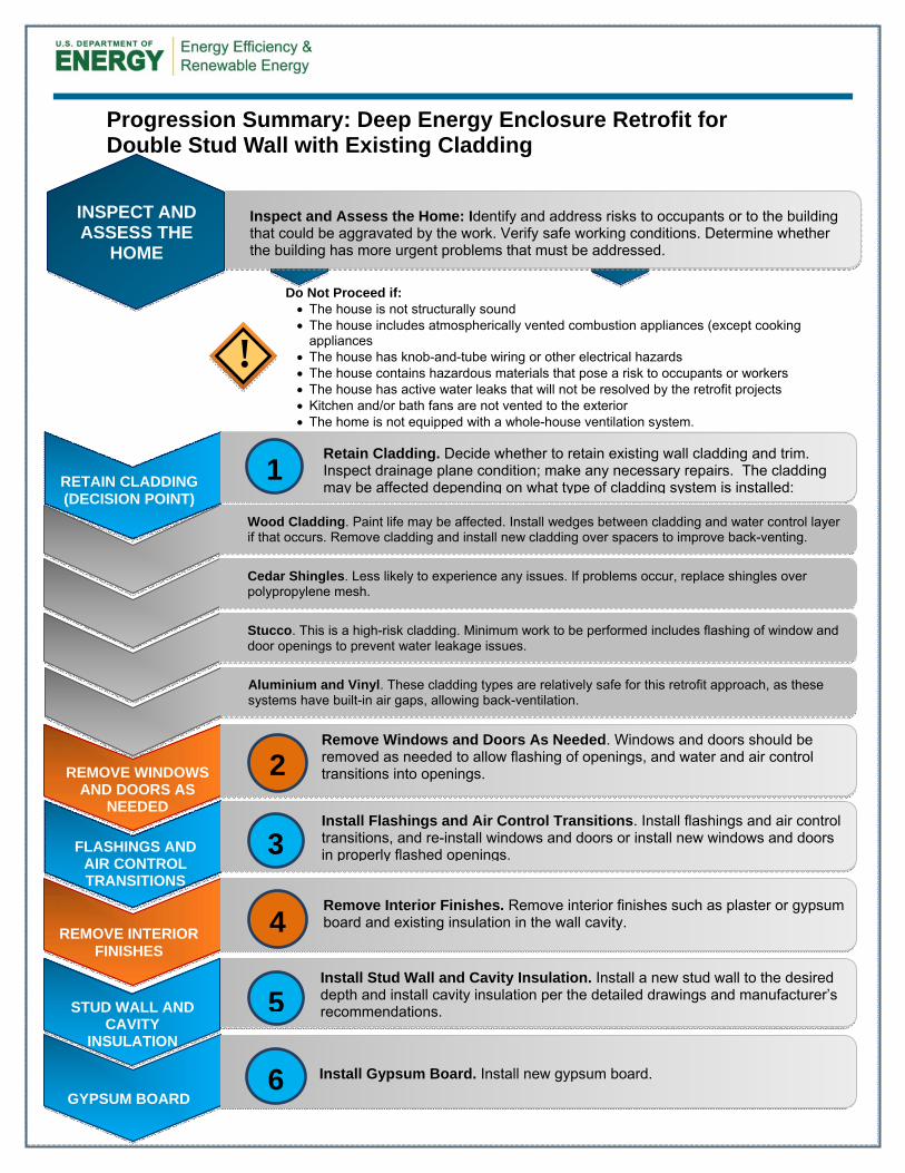
Progression Summary: Deep Energy Enclosure Retrofit for Double Stud Wall with Existing Cladding
ss
RETAIN CLADDING (DECISION POINT)
Retain Cladding. Decide whether to retain existing wall cladding and trim. Inspect drainage plane condition; make any necessary repairs. The cladding may be affected depending on what type of cladding system is installed:
FLASHINGS AND AIR CONTROL TRANSITIONS
Install Flashings and Air Control Transitions. Install flashings and air control transitions, and re-install windows and doors or install new windows and doors in properly flashed openings.
STUD WALL AND CAVITY
INSULATION
Install Stud Wall and Cavity Insulation. Install a new stud wall to the desired depth and install cavity insulation per the detailed drawings and manufacturer’s recommendations.
Do Not Proceed if: The house is not structurally sound The house includes atmospherically vented combustion appliances (except cooking
appliances The house has knob-and-tube wiring or other electrical hazards The house contains hazardous materials that pose a risk to occupants or workers The house has active water leaks that will not be resolved by the retrofit projects Kitchen and/or bath fans are not vented to the exterior The home is not equipped with a whole-house ventilation system.
!
Install Gypsum Board. Install new gypsum board.
GYPSUM BOARD 6
3
5
Remove Windows and Doors As Needed. Windows and doors should be removed as needed to allow flashing of openings, and water and air control transitions into openings.
4
Remove Interior Finishes. Remove interior finishes such as plaster or gypsum board and existing insulation in the wall cavity.
REMOVE INTERIOR FINISHES
2 REMOVE WINDOWS AND DOORS AS
NEEDED
Wood Cladding. Paint life may be affected. Install wedges between cladding and water control layer
if that occurs. Remove cladding and install new cladding over spacers to improve back-venting.
Cedar Shingles. Less likely to experience any issues. If problems occur, replace shingles over
polypropylene mesh.
Stucco. This is a high-risk cladding. Minimum work to be performed includes flashing of window and
door openings to prevent water leakage issues.
Aluminium and Vinyl. These cladding types are relatively safe for this retrofit approach, as these
systems have built-in air gaps, allowing back-ventilation.
1
INSPECT AND ASSESS THE
HOME
Inspect and Assess the Home: Identify and address risks to occupants or to the building that could be aggravated by the work. Verify safe working conditions. Determine whether the building has more urgent problems that must be addressed.
4
1 Introduction
This Measure Guideline describes a deep energy enclosure retrofit (DEER) solution that involves insulation to the interior of the wall assembly, with the use of a double stud wall. The guide describes two approaches to retrofitting the existing the walls: one involving replacement of the existing cladding, and the other that leaves the existing cladding in place. It discusses the design principles related to the use of various insulation types and provides strategies and procedures for implementing the double stud wall retrofit. It also evaluates important moisture-related and indoor air quality measures that need to be implemented to achieve a durable, high performance wall. An interior retrofit is typically less desirable than an exterior retrofit; exterior retrofits allow complete inspection and renovation of exterior moisture control detailing and layers. Interior retrofits are disruptive to the living space and its occupants, and the interior double stud wall reduces usable space. However, despite the advantages of exterior retrofits, many buildings must be retrofitted on the interior, for reasons such as historic preservation, zoning or space restrictions, or aesthetics. The double-stud wall approach is also suitable if a full replacement of services within the exterior wall is planned. An interior retrofit may or may not be less expensive, depending on such factors as access and whether a gut rehabilitation is planned. However, once an interior retrofit has been chosen, double stud walls can be more cost effective than using exterior insulating sheathing. Double stud walls insulated with cellulose or low-density open cell spray foam can have R-values of 40 or higher. They have been used in high performance housing since the 1970s: their advantages include trade familiarity with construction detailing (especially at the exterior), and the use of commonly available construction materials (Ueno 2014). However, double stud walls have a higher risk of interior-sourced condensation moisture damage, when compared with high-R approaches using exterior insulating sheathing. There are specific moisture control principles that must be followed for a successful double stud wall insulated retrofit. Controlling bulk water entry into the wall and maintaining certain levels of relative humidity (RH) are factors of vital importance. Loose-fill fibrous insulation, such as cellulose, is a common choice for double-stud walls due to its lower cost (in most markets). However, cellulose is an air-permeable insulation, unlike spray foams, raising moisture risks (Ueno 2014). A lower risk approach involves spraying insulating foam in the entire double stud wall cavity. Low-density, semi-permeable open cell spray polyurethane foam (ocSPF) is a good choice; in monitored data, sheathing moisture contents are lower than those in cellulose walls. Another assembly option is to combine spray foam with fibrous, air-permeable insulation (fiberglass or cellulose) to create a lower cost “hybrid” high-R wall assembly. The common name for this assembly is “flash and batt” (Maines 2011). High-density, closed cell polyurethane spray foam (ccSPF) is generally recommended for this application. The relative thickness of the foam layer is a function of wintertime condensation control, and thus local climate.
5
This Measure Guideline is important to the high performance retrofit industry because it demonstrates techniques for implementing interior double stud walls in high performance enclosure retrofits. The information included in the guide is based on the latest research performed for the Department of Energy (DOE) Building America program. This Measure Guideline is intended to support contractors implementing an interior insulation high performance enclosure retrofit as well as designers looking to design such retrofits. The Measure Guideline may also be helpful to building owners wishing to learn more about strategies available for deep energy enclosure retrofit of wood-framed residential buildings.
6
2 Decision Making Criteria
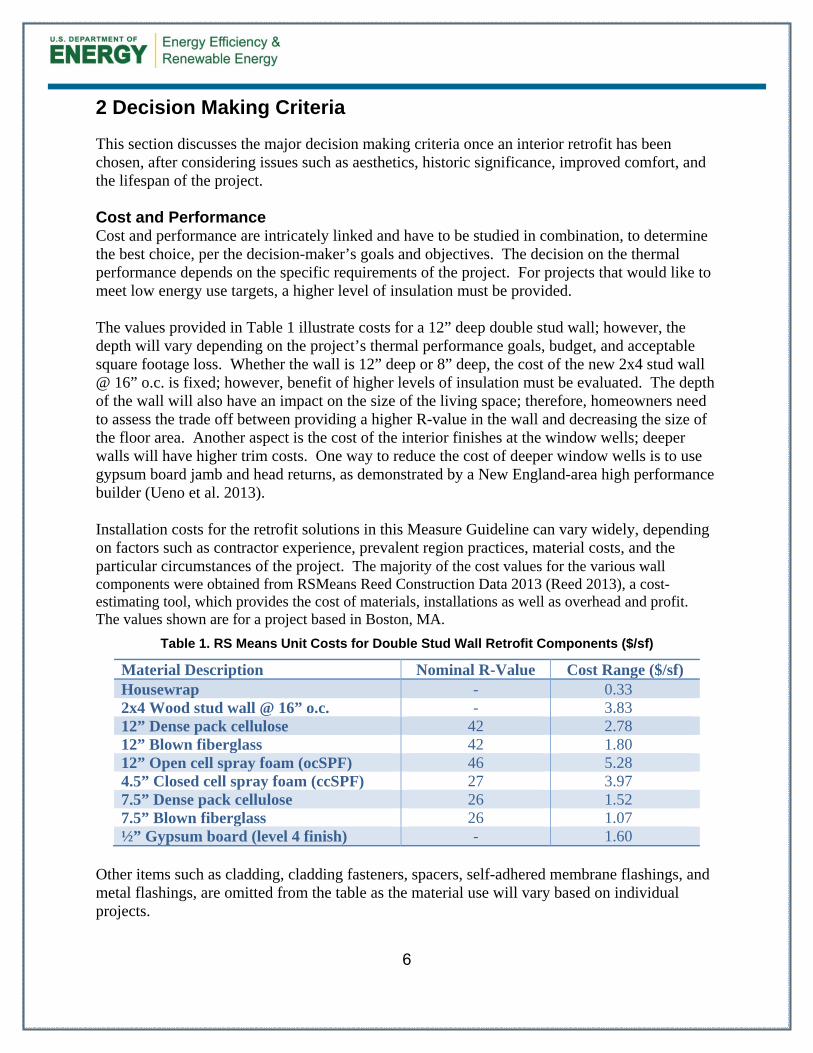
This section discusses the major decision making criteria once an interior retrofit has been chosen, after considering issues such as aesthetics, historic significance, improved comfort, and the lifespan of the project. Cost and Performance Cost and performance are intricately linked and have to be studied in combination, to determine the best choice, per the decision-maker’s goals and objectives. The decision on the thermal performance depends on the specific requirements of the project. For projects that would like to meet low energy use targets, a higher level of insulation must be provided. The values provided in Table 1 illustrate costs for a 12” deep double stud wall; however, the depth will vary depending on the project’s thermal performance goals, budget, and acceptable square footage loss. Whether the wall is 12” deep or 8” deep, the cost of the new 2x4 stud wall @ 16” o.c. is fixed; however, benefit of higher levels of insulation must be evaluated. The depth of the wall will also have an impact on the size of the living space; therefore, homeowners need to assess the trade off between providing a higher R-value in the wall and decreasing the size of the floor area. Another aspect is the cost of the interior finishes at the window wells; deeper walls will have higher trim costs. One way to reduce the cost of deeper window wells is to use gypsum board jamb and head returns, as demonstrated by a New England-area high performance builder (Ueno et al. 2013). Installation costs for the retrofit solutions in this Measure Guideline can vary widely, depending on factors such as contractor experience, prevalent region practices, material costs, and the particular circumstances of the project. The majority of the cost values for the various wall components were obtained from RSMeans Reed Construction Data 2013 (Reed 2013), a cost-estimating tool, which provides the cost of materials, installations as well as overhead and profit. The values shown are for a project based in Boston, MA.
Table 1. RS Means Unit Costs for Double Stud Wall Retrofit Components ($/sf)
Other items such as cladding, cladding fasteners, spacers, self-adhered membrane flashings, and metal flashings, are omitted from the table as the material use will vary based on individual projects.
7
Water Leakage Management Replacing (or not replacing) the cladding and the water membrane can have a significant effect on the durability of the wall. Adding additional interior insulation (in the form of a double stud wall) reduces heat flow through the wall, and thus ability to dry. Therefore, previously survivable water leaks might cause long-term damage after the retrofit of insulation (Lstiburek 2008b). Deciding whether to replace the cladding should be evaluated based on the existing conditions and available project budget. One key assessment is to partially disassemble the wall, to determine the presence and condition of the water control membrane (“drainage plane”). If the drainage plane is not present or deteriorated, the cladding should be replaced. In addition, the existing cladding should be carefully inspected to ensure that are no active water leaks into the wall; this might be done by inspection of the exterior sheathing from the interior (part of the interior retrofit project). Replacing the water control membrane (“drainage plane”) and installing new cladding with an air gap (“drained and ventilated cavity”) will greatly enhance the durability of the wall due to greater drainage and ventilation drying (see Lstiburek 2013 for discussion and details). It would generally be a prudent step in any double stud insulation retrofit. Air Leakage Management It is highly risky to design a retrofit that allows significant air leakage; therefore, the air leakage performance of the retrofit strategies must be evaluated before making a decision whether or not to replace the cladding the water and air control membrane. Experience has shown that air barrier systems formed by careful taping, caulking, use of appropriate air sealing materials like spray polyurethane products and fully-adhered membranes are quite likely to achieve airtightness when properly installed using standard quality control measures. Constructibility The ease of construction might be a consideration depending on the specific requirement of the decision-maker. For projects where the homeowners wish to perform the retrofit themselves, it might be worthwhile to consider options that involve low-tech construction techniques and are easier to implement. How easy a measure is to implement can greatly impact the success of a project. Difficult details and construction sequences often lead to increased cost and reduced performance. Efficiency in construction is driven by simple repeatable details and common construction practice. The more that a measure deviates from common construction techniques (or requires overly complicated sequences involving multiple trades), the more likely that the work will not be completed with the intended result.
8
A key benefit to the use of an interior double stud wall with cavity insulation is that it does not significantly change standard construction practices and details (e.g., compared to an exterior rigid insulation wall). The installation of the water and air control membrane and cladding remains the same, with only a slight modification of adding ventilation spacers behind the cladding. The new non-load bearing 2x4 stud wall inboard of the existing structural wall will have electrical and plumbing services installed per standard practice. The only difference from standard practice is the interior finishes at the window wells.
9
3 Technical Description
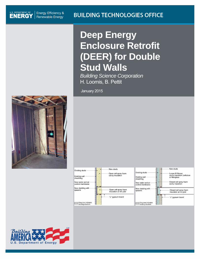
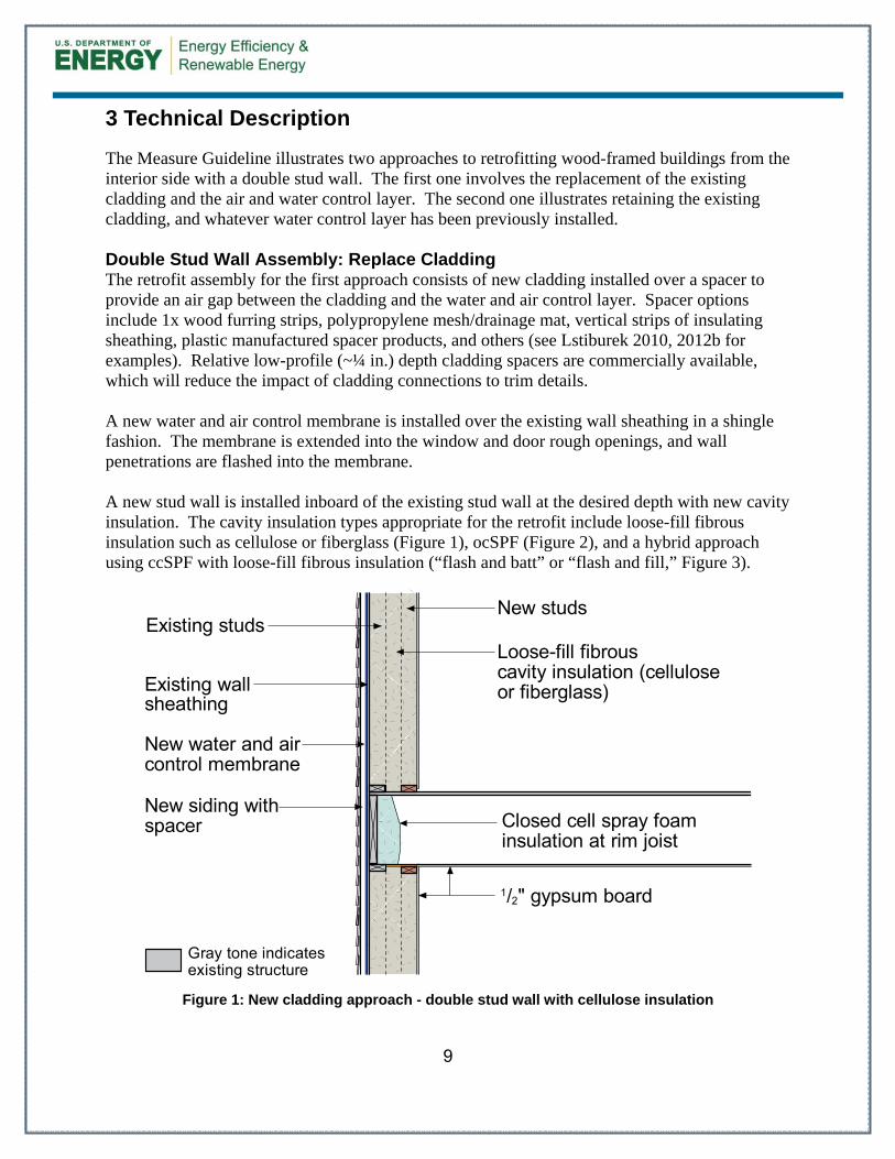
The Measure Guideline illustrates two approaches to retrofitting wood-framed buildings from the interior side with a double stud wall. The first one involves the replacement of the existing cladding and the air and water control layer. The second one illustrates retaining the existing cladding, and whatever water control layer has been previously installed. Double Stud Wall Assembly: Replace Cladding The retrofit assembly for the first approach consists of new cladding installed over a spacer to provide an air gap between the cladding and the water and air control layer. Spacer options include 1x wood furring strips, polypropylene mesh/drainage mat, vertical strips of insulating sheathing, plastic manufactured spacer products, and others (see Lstiburek 2010, 2012b for examples). Relative low-profile (~¼ in.) depth cladding spacers are commercially available, which will reduce the impact of cladding connections to trim details. A new water and air control membrane is installed over the existing wall sheathing in a shingle fashion. The membrane is extended into the window and door rough openings, and wall penetrations are flashed into the membrane. A new stud wall is installed inboard of the existing stud wall at the desired depth with new cavity insulation. The cavity insulation types appropriate for the retrofit include loose-fill fibrous insulation such as cellulose or fiberglass (Figure 1), ocSPF (Figure 2), and a hybrid approach using ccSPF with loose-fill fibrous insulation (“flash and batt” or “flash and fill,” Figure 3).
Figure 1: New cladding approach - double stud wall with cellulose insulation
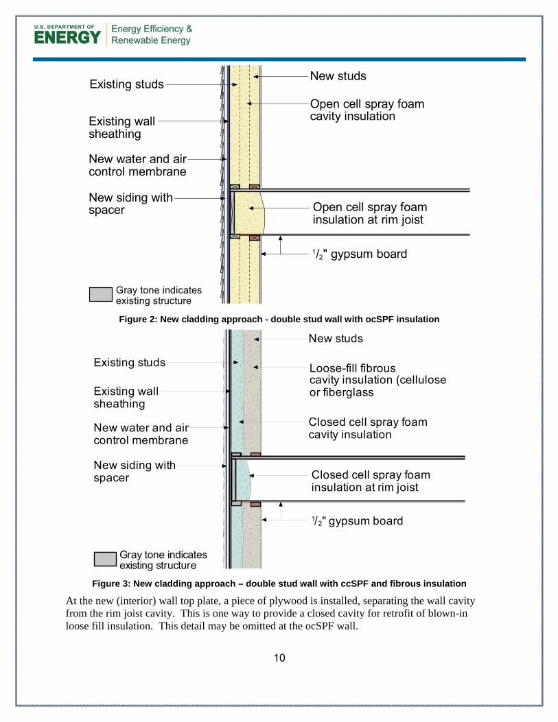
Figure 2: New cladding approach - double stud wall with ocSPF insulation
Figure 3: New cladding approach – double stud wall with ccSPF and fibrous insulation
At the new (interior) wall top plate, a piece of plywood is installed, separating the wall cavity from the rim joist cavity. This is one way to provide a closed cavity for retrofit of blown-in loose fill insulation. This detail may be omitted at the ocSPF wall.
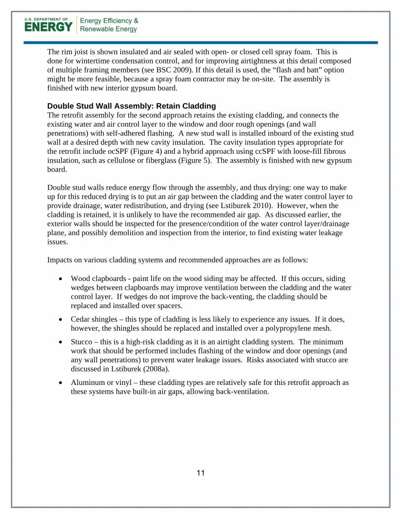
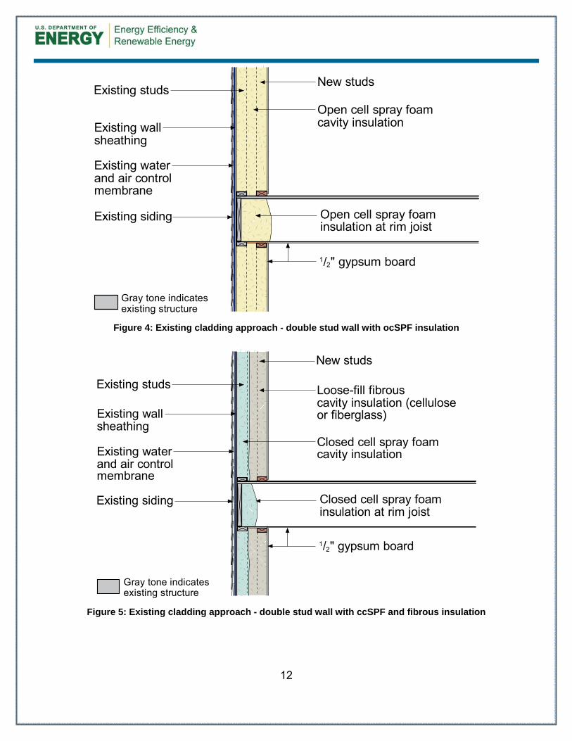
The rim joist is shown insulated and air sealed with open- or closed cell spray foam. This is done for wintertime condensation control, and for improving airtightness at this detail composed of multiple framing members (see BSC 2009). If this detail is used, the “flash and batt” option might be more feasible, because a spray foam contractor may be on-site. The assembly is finished with new interior gypsum board. Double Stud Wall Assembly: Retain Cladding The retrofit assembly for the second approach retains the existing cladding, and connects the existing water and air control layer to the window and door rough openings (and wall penetrations) with self-adhered flashing. A new stud wall is installed inboard of the existing stud wall at a desired depth with new cavity insulation. The cavity insulation types appropriate for the retrofit include ocSPF (Figure 4) and a hybrid approach using ccSPF with loose-fill fibrous insulation, such as cellulose or fiberglass (Figure 5). The assembly is finished with new gypsum board. Double stud walls reduce energy flow through the assembly, and thus drying: one way to make up for this reduced drying is to put an air gap between the cladding and the water control layer to provide drainage, water redistribution, and drying (see Lstiburek 2010). However, when the cladding is retained, it is unlikely to have the recommended air gap. As discussed earlier, the exterior walls should be inspected for the presence/condition of the water control layer/drainage plane, and possibly demolition and inspection from the interior, to find existing water leakage issues. Impacts on various cladding systems and recommended approaches are as follows:
Wood clapboards - paint life on the wood siding may be affected. If this occurs, siding wedges between clapboards may improve ventilation between the cladding and the water control layer. If wedges do not improve the back-venting, the cladding should be replaced and installed over spacers.
Cedar shingles – this type of cladding is less likely to experience any issues. If it does, however, the shingles should be replaced and installed over a polypropylene mesh.
Stucco – this is a high-risk cladding as it is an airtight cladding system. The minimum work that should be performed includes flashing of the window and door openings (and any wall penetrations) to prevent water leakage issues. Risks associated with stucco are discussed in Lstiburek (2008a).
Aluminum or vinyl – these cladding types are relatively safe for this retrofit approach as these systems have built-in air gaps, allowing back-ventilation.
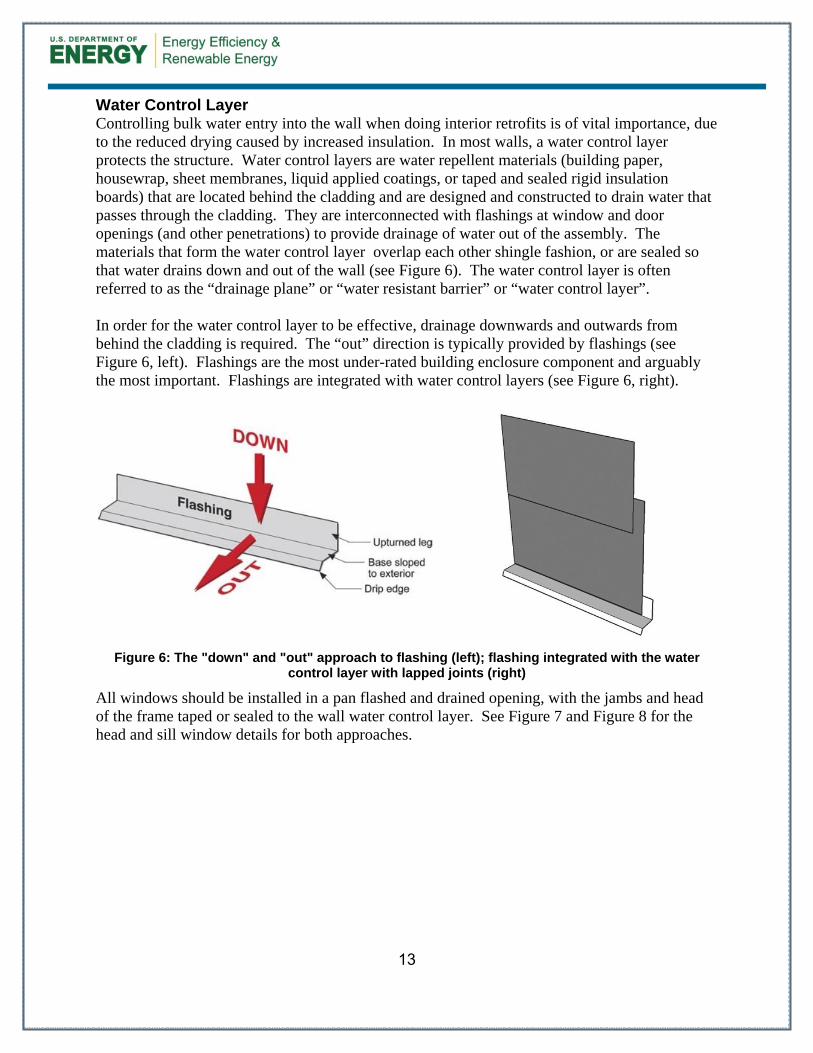
Water Control Layer Controlling bulk water entry into the wall when doing interior retrofits is of vital importance, due to the reduced drying caused by increased insulation. In most walls, a water control layer protects the structure. Water control layers are water repellent materials (building paper, housewrap, sheet membranes, liquid applied coatings, or taped and sealed rigid insulation boards) that are located behind the cladding and are designed and constructed to drain water that passes through the cladding. They are interconnected with flashings at window and door openings (and other penetrations) to provide drainage of water out of the assembly. The materials that form the water control layer overlap each other shingle fashion, or are sealed so that water drains down and out of the wall (see Figure 6). The water control layer is often referred to as the “drainage plane” or “water resistant barrier” or “water control layer”. In order for the water control layer to be effective, drainage downwards and outwards from behind the cladding is required. The “out” direction is typically provided by flashings (see Figure 6, left). Flashings are the most under-rated building enclosure component and arguably the most important. Flashings are integrated with water control layers (see Figure 6, right).
Figure 6: The "down" and "out" approach to flashing (left); flashing integrated with the water control layer with lapped joints (right)
All windows should be installed in a pan flashed and drained opening, with the jambs and head of the frame taped or sealed to the wall water control layer. See Figure 7 and Figure 8 for the head and sill window details for both approaches.
14
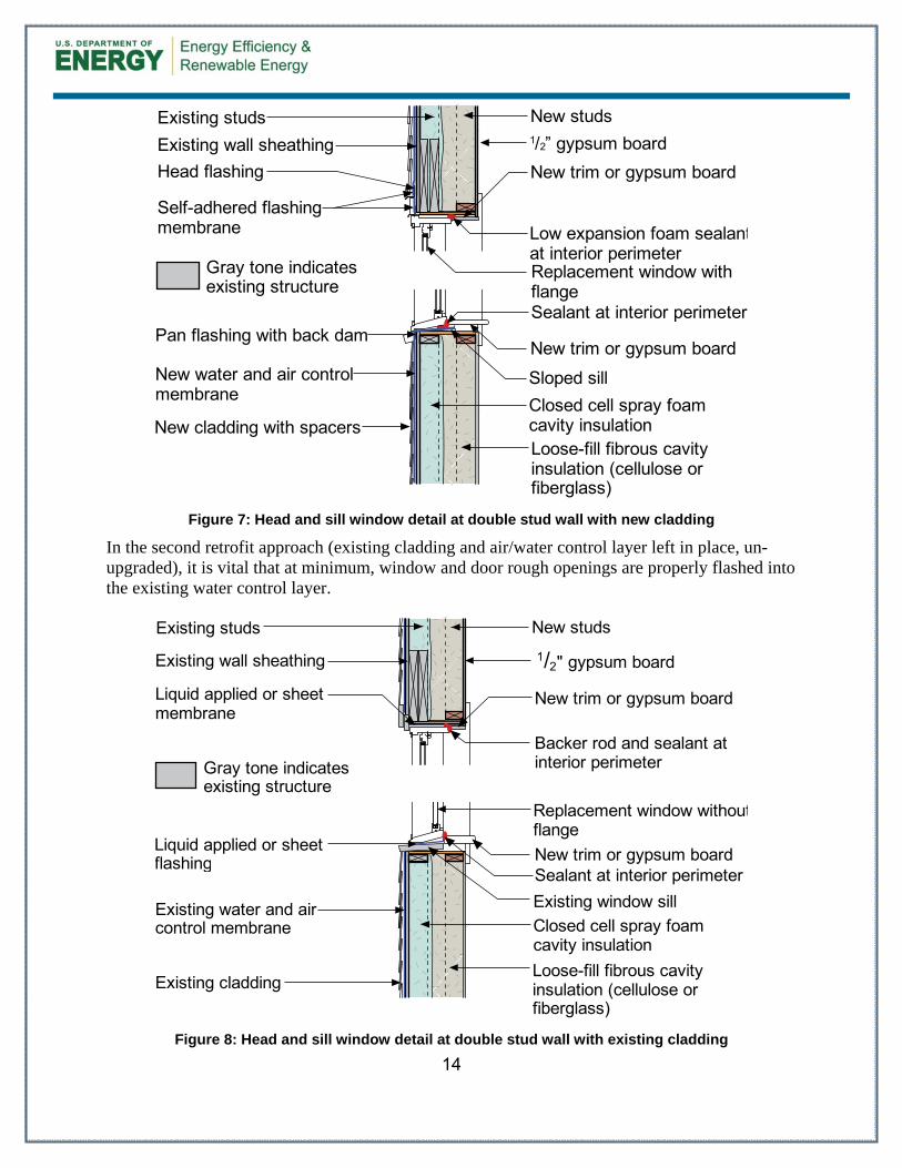
Figure 7: Head and sill window detail at double stud wall with new cladding
In the second retrofit approach (existing cladding and air/water control layer left in place, un-upgraded), it is vital that at minimum, window and door rough openings are properly flashed into the existing water control layer.
Figure 8: Head and sill window detail at double stud wall with existing cladding
Sealant at interior perimeterNew trim or gypsum board
New studs
1/2" gypsum board
New trim or gypsum board
15
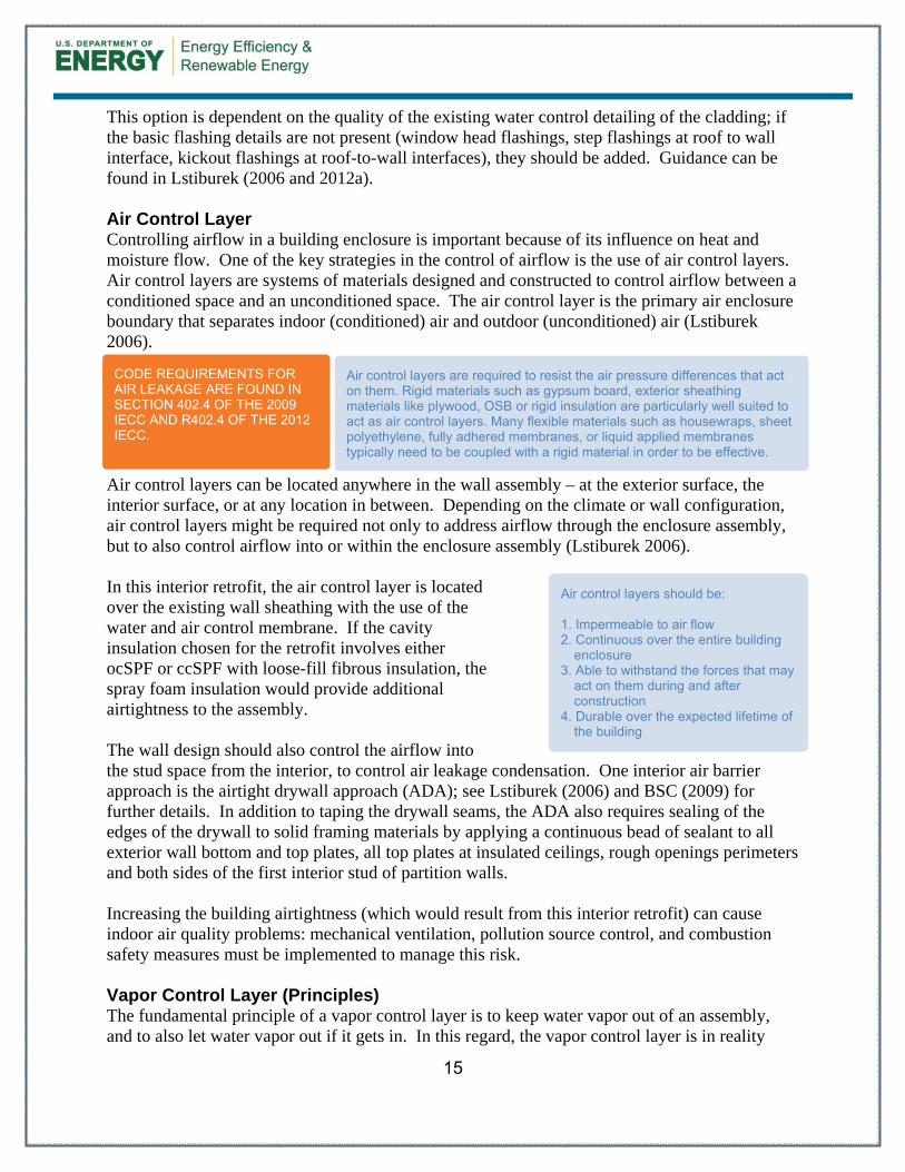
This option is dependent on the quality of the existing water control detailing of the cladding; if the basic flashing details are not present (window head flashings, step flashings at roof to wall interface, kickout flashings at roof-to-wall interfaces), they should be added. Guidance can be found in Lstiburek (2006 and 2012a). Air Control Layer Controlling airflow in a building enclosure is important because of its influence on heat and moisture flow. One of the key strategies in the control of airflow is the use of air control layers. Air control layers are systems of materials designed and constructed to control airflow between a conditioned space and an unconditioned space. The air control layer is the primary air enclosure boundary that separates indoor (conditioned) air and outdoor (unconditioned) air (Lstiburek 2006).
Air control layers can be located anywhere in the wall assembly – at the exterior surface, the interior surface, or at any location in between. Depending on the climate or wall configuration, air control layers might be required not only to address airflow through the enclosure assembly, but to also control airflow into or within the enclosure assembly (Lstiburek 2006). In this interior retrofit, the air control layer is located over the existing wall sheathing with the use of the water and air control membrane. If the cavity insulation chosen for the retrofit involves either ocSPF or ccSPF with loose-fill fibrous insulation, the spray foam insulation would provide additional airtightness to the assembly. The wall design should also control the airflow into the stud space from the interior, to control air leakage condensation. One interior air barrier approach is the airtight drywall approach (ADA); see Lstiburek (2006) and BSC (2009) for further details. In addition to taping the drywall seams, the ADA also requires sealing of the edges of the drywall to solid framing materials by applying a continuous bead of sealant to all exterior wall bottom and top plates, all top plates at insulated ceilings, rough openings perimeters and both sides of the first interior stud of partition walls. Increasing the building airtightness (which would result from this interior retrofit) can cause indoor air quality problems: mechanical ventilation, pollution source control, and combustion safety measures must be implemented to manage this risk. Vapor Control Layer (Principles) The fundamental principle of a vapor control layer is to keep water vapor out of an assembly, and to also let water vapor out if it gets in. In this regard, the vapor control layer is in reality
Air control layers should be: 1. Impermeable to air flow 2. Continuous over the entire building
enclosure 3. Able to withstand the forces that may
act on them during and after construction
4. Durable over the expected lifetime of the building
CODE REQUIREMENTS FOR AIR LEAKAGE ARE FOUND IN SECTION 402.4 OF THE 2009 IECC AND R402.4 OF THE 2012 IECC.
Air control layers are required to resist the air pressure differences that act on them. Rigid materials such as gypsum board, exterior sheathing materials like plywood, OSB or rigid insulation are particularly well suited to act as air control layers. Many flexible materials such as housewraps, sheet polyethylene, fully adhered membranes, or liquid applied membranes typically need to be coupled with a rigid material in order to be effective.
16
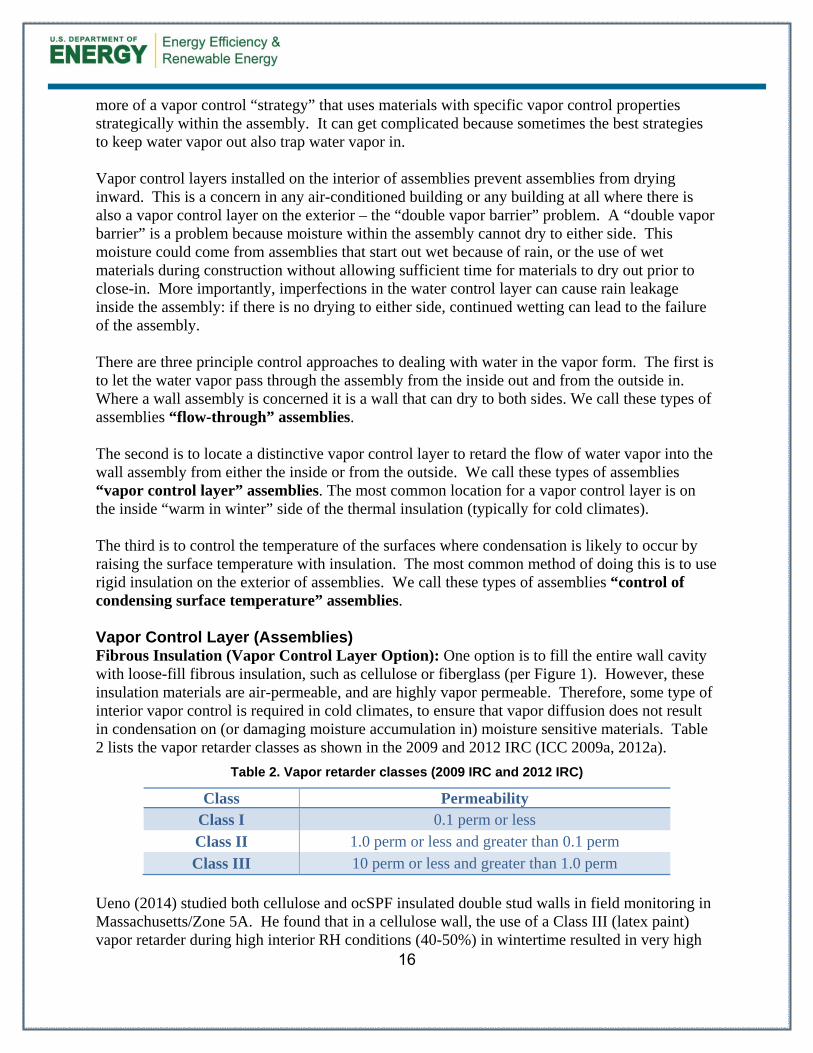
more of a vapor control “strategy” that uses materials with specific vapor control properties strategically within the assembly. It can get complicated because sometimes the best strategies to keep water vapor out also trap water vapor in. Vapor control layers installed on the interior of assemblies prevent assemblies from drying inward. This is a concern in any air-conditioned building or any building at all where there is also a vapor control layer on the exterior – the “double vapor barrier” problem. A “double vapor barrier” is a problem because moisture within the assembly cannot dry to either side. This moisture could come from assemblies that start out wet because of rain, or the use of wet materials during construction without allowing sufficient time for materials to dry out prior to close-in. More importantly, imperfections in the water control layer can cause rain leakage inside the assembly: if there is no drying to either side, continued wetting can lead to the failure of the assembly. There are three principle control approaches to dealing with water in the vapor form. The first is to let the water vapor pass through the assembly from the inside out and from the outside in. Where a wall assembly is concerned it is a wall that can dry to both sides. We call these types of assemblies “flow-through” assemblies. The second is to locate a distinctive vapor control layer to retard the flow of water vapor into the wall assembly from either the inside or from the outside. We call these types of assemblies “vapor control layer” assemblies. The most common location for a vapor control layer is on the inside “warm in winter” side of the thermal insulation (typically for cold climates). The third is to control the temperature of the surfaces where condensation is likely to occur by raising the surface temperature with insulation. The most common method of doing this is to use rigid insulation on the exterior of assemblies. We call these types of assemblies “control of condensing surface temperature” assemblies. Vapor Control Layer (Assemblies) Fibrous Insulation (Vapor Control Layer Option): One option is to fill the entire wall cavity with loose-fill fibrous insulation, such as cellulose or fiberglass (per Figure 1). However, these insulation materials are air-permeable, and are highly vapor permeable. Therefore, some type of interior vapor control is required in cold climates, to ensure that vapor diffusion does not result in condensation on (or damaging moisture accumulation in) moisture sensitive materials. Table 2 lists the vapor retarder classes as shown in the 2009 and 2012 IRC (ICC 2009a, 2012a).
Table 2. Vapor retarder classes (2009 IRC and 2012 IRC)
Class Permeability Class I 0.1 perm or less Class II 1.0 perm or less and greater than 0.1 perm Class III 10 perm or less and greater than 1.0 perm
Ueno (2014) studied both cellulose and ocSPF insulated double stud walls in field monitoring in Massachusetts/Zone 5A. He found that in a cellulose wall, the use of a Class III (latex paint) vapor retarder during high interior RH conditions (40-50%) in wintertime resulted in very high
17
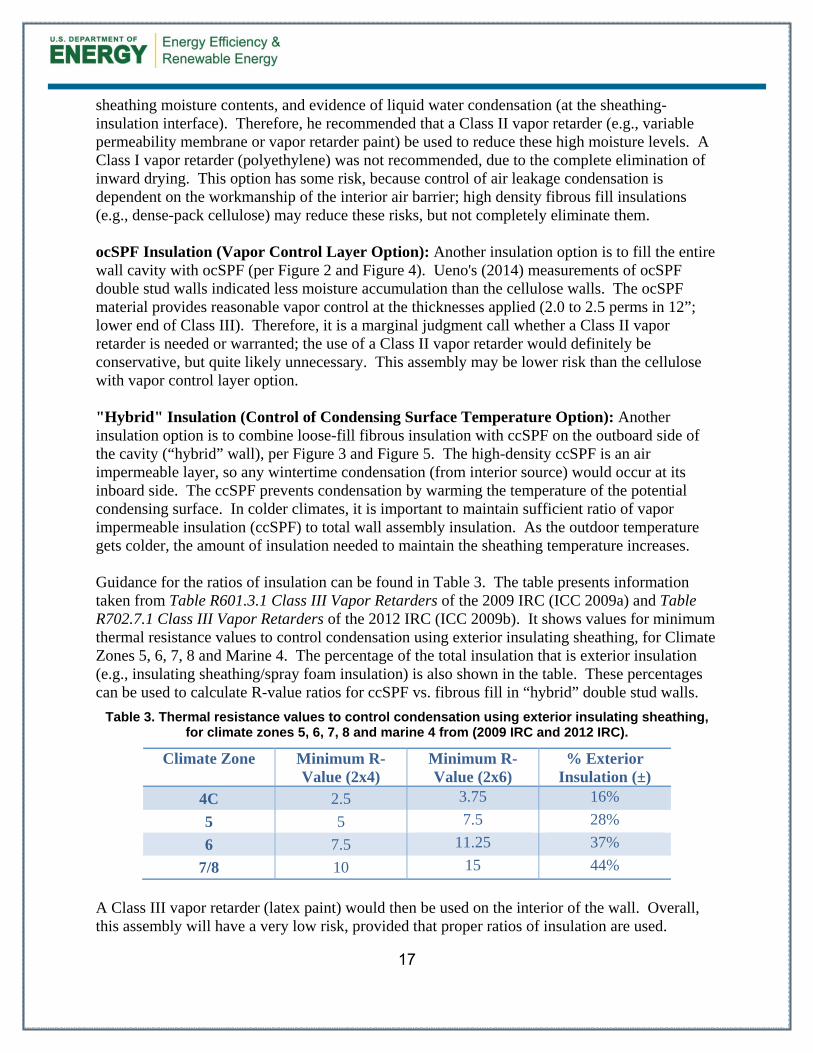
sheathing moisture contents, and evidence of liquid water condensation (at the sheathing-insulation interface). Therefore, he recommended that a Class II vapor retarder (e.g., variable permeability membrane or vapor retarder paint) be used to reduce these high moisture levels. A Class I vapor retarder (polyethylene) was not recommended, due to the complete elimination of inward drying. This option has some risk, because control of air leakage condensation is dependent on the workmanship of the interior air barrier; high density fibrous fill insulations (e.g., dense-pack cellulose) may reduce these risks, but not completely eliminate them. ocSPF Insulation (Vapor Control Layer Option): Another insulation option is to fill the entire wall cavity with ocSPF (per Figure 2 and Figure 4). Ueno's (2014) measurements of ocSPF double stud walls indicated less moisture accumulation than the cellulose walls. The ocSPF material provides reasonable vapor control at the thicknesses applied (2.0 to 2.5 perms in 12”; lower end of Class III). Therefore, it is a marginal judgment call whether a Class II vapor retarder is needed or warranted; the use of a Class II vapor retarder would definitely be conservative, but quite likely unnecessary. This assembly may be lower risk than the cellulose with vapor control layer option. "Hybrid" Insulation (Control of Condensing Surface Temperature Option): Another insulation option is to combine loose-fill fibrous insulation with ccSPF on the outboard side of the cavity (“hybrid” wall), per Figure 3 and Figure 5. The high-density ccSPF is an air impermeable layer, so any wintertime condensation (from interior source) would occur at its inboard side. The ccSPF prevents condensation by warming the temperature of the potential condensing surface. In colder climates, it is important to maintain sufficient ratio of vapor impermeable insulation (ccSPF) to total wall assembly insulation. As the outdoor temperature gets colder, the amount of insulation needed to maintain the sheathing temperature increases. Guidance for the ratios of insulation can be found in Table 3. The table presents information taken from Table R601.3.1 Class III Vapor Retarders of the 2009 IRC (ICC 2009a) and Table R702.7.1 Class III Vapor Retarders of the 2012 IRC (ICC 2009b). It shows values for minimum thermal resistance values to control condensation using exterior insulating sheathing, for Climate Zones 5, 6, 7, 8 and Marine 4. The percentage of the total insulation that is exterior insulation (e.g., insulating sheathing/spray foam insulation) is also shown in the table. These percentages can be used to calculate R-value ratios for ccSPF vs. fibrous fill in “hybrid” double stud walls.
Table 3. Thermal resistance values to control condensation using exterior insulating sheathing, for climate zones 5, 6, 7, 8 and marine 4 from (2009 IRC and 2012 IRC).
Climate Zone Minimum R-Value (2x4)
Minimum R-Value (2x6)
% Exterior Insulation (±)
4C 2.5 3.75 16%
5 5 7.5 28%
6 7.5 11.25 37%
7/8 10 15 44%
A Class III vapor retarder (latex paint) would then be used on the interior of the wall. Overall, this assembly will have a very low risk, provided that proper ratios of insulation are used.
18
More detailed analysis could be done to optimize the assembly: hygrothermal modeling, when used appropriately, would provide the most refined analysis of the risk. However, analysis at this level is seldom required for residential construction. Other methods such as a dewpoint calculation that looks to limit the sheathing temperature to 45°F based on the average temperature over the coldest three months of the year (assumed interior conditions of 35% RH and 70°F) is a reasonable check against condensation risks. These methods are discussed in Lstiburek (2006) and Straube (2011). Thermal Control Layer The function of the thermal control layer is to control the flow of heat from both the inside to the outside and from the outside to the inside. As with the other control layers the most important factor to consider when dealing with the thermal control layer is its continuity. The amount of cavity insulation added to the assembly will be dependent on the climate zone and design goals for the project. The minimum levels should be based on the minimum requirements for vapor control (see previous section) and minimum requirements based on the current adopted building code and energy code, respectively, for the project. Additional insulation can be added above these minimums to create high R-Value wall assemblies.
Table 4. Recommended Minimum R-Value for Wall Enclosures
Framed Wall Minimum R-Value
Climate Zone 2009 IECC 2012 IECC
1 13 13
2 13 13
3 13 20 or 13+5
4 except Marine 13 20 or 13+5
5 and Marine 4 20 or 13+5 20 or 13+5
6 20 or 13+5 20 + 5 or 13 + 10
7 and 8 21 20 + 5 or 13 + 10
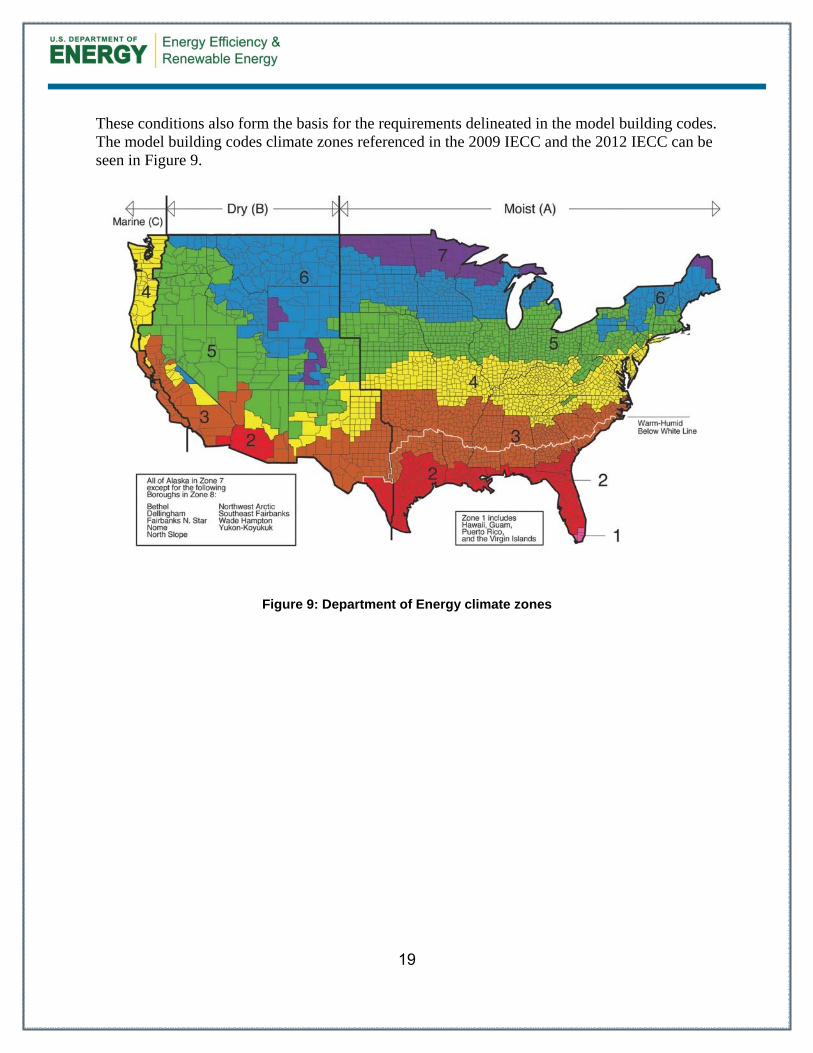
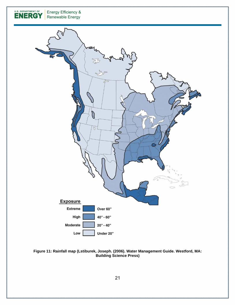
Table 4 provides the minimum thermal resistance (R-value) requirements for framed walls specified in the 2009 IECC (ICC 2009b) and the 2012 IECC (ICC 2012b), based on climate zone. Climate Zones and Building Environments Buildings should be suited to their environment. Building enclosures should be designed for a specific hygrothermal region (Figure 10), rain exposure zone (Figure 11) and interior climate. For most residential buildings, interiors are assumed to be conditioned to around 70°F in the winter and 75°F in the summer. Relative humidities should be limited to 35 percent (no higher) during the coldest month in winter and 65 percent (no higher) in the summer.
CODE REQUIREMENTS FOR THERMAL INSULATION ARE FOUND IN SECTION 402 OF THE 2009 IECC AND R402 OF THE 2012 IECC.
19
These conditions also form the basis for the requirements delineated in the model building codes. The model building codes climate zones referenced in the 2009 IECC and the 2012 IECC can be seen in Figure 9.
Figure 9: Department of Energy climate zones
20
Figure 10: Hygrothermal map (Lstiburek, Joseph. (2006). Builder's Guide to Cold Climates. Westford, MA: Building Science Press)
21
Figure 11: Rainfall map (Lstiburek, Joseph. (2006). Water Management Guide. Westford, MA: Building Science Press)
22
4 Measure Implementation
New Cladding Option
Existing Cladding Option
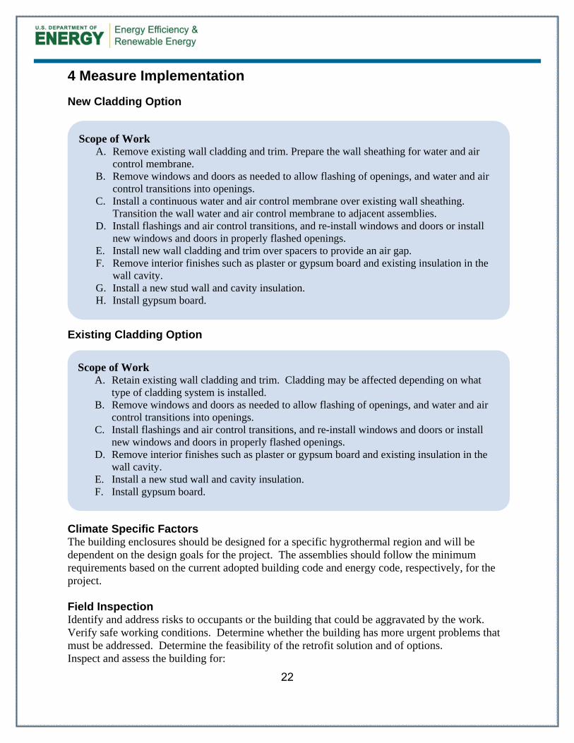
Climate Specific Factors The building enclosures should be designed for a specific hygrothermal region and will be dependent on the design goals for the project. The assemblies should follow the minimum requirements based on the current adopted building code and energy code, respectively, for the project. Field Inspection Identify and address risks to occupants or the building that could be aggravated by the work. Verify safe working conditions. Determine whether the building has more urgent problems that must be addressed. Determine the feasibility of the retrofit solution and of options. Inspect and assess the building for:
Scope of Work A. Remove existing wall cladding and trim. Prepare the wall sheathing for water and air
control membrane. B. Remove windows and doors as needed to allow flashing of openings, and water and air
control transitions into openings. C. Install a continuous water and air control membrane over existing wall sheathing.
Transition the wall water and air control membrane to adjacent assemblies. D. Install flashings and air control transitions, and re-install windows and doors or install
new windows and doors in properly flashed openings. E. Install new wall cladding and trim over spacers to provide an air gap. F. Remove interior finishes such as plaster or gypsum board and existing insulation in the
wall cavity. G. Install a new stud wall and cavity insulation. H. Install gypsum board.
Scope of Work A. Retain existing wall cladding and trim. Cladding may be affected depending on what
type of cladding system is installed. B. Remove windows and doors as needed to allow flashing of openings, and water and air
control transitions into openings. C. Install flashings and air control transitions, and re-install windows and doors or install
new windows and doors in properly flashed openings. D. Remove interior finishes such as plaster or gypsum board and existing insulation in the
wall cavity. E. Install a new stud wall and cavity insulation. F. Install gypsum board.
23
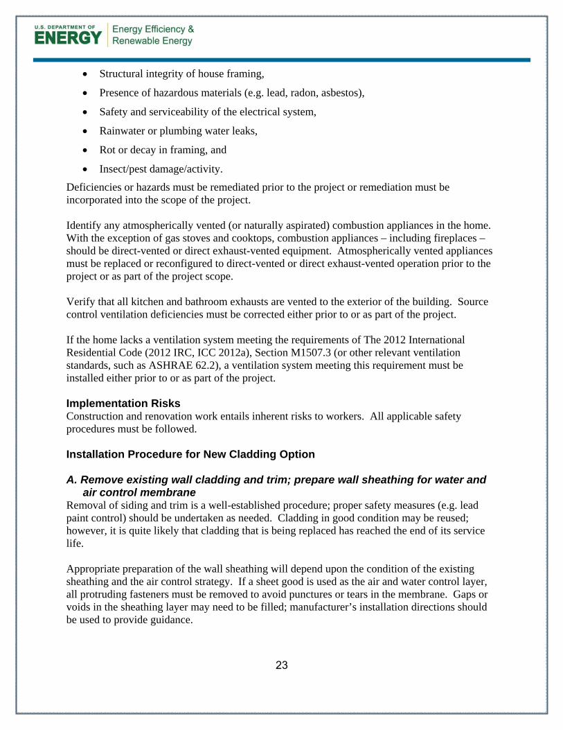
Structural integrity of house framing,
Presence of hazardous materials (e.g. lead, radon, asbestos),
Safety and serviceability of the electrical system,
Rainwater or plumbing water leaks,
Rot or decay in framing, and
Insect/pest damage/activity.
Deficiencies or hazards must be remediated prior to the project or remediation must be incorporated into the scope of the project. Identify any atmospherically vented (or naturally aspirated) combustion appliances in the home. With the exception of gas stoves and cooktops, combustion appliances – including fireplaces – should be direct-vented or direct exhaust-vented equipment. Atmospherically vented appliances must be replaced or reconfigured to direct-vented or direct exhaust-vented operation prior to the project or as part of the project scope. Verify that all kitchen and bathroom exhausts are vented to the exterior of the building. Source control ventilation deficiencies must be corrected either prior to or as part of the project. If the home lacks a ventilation system meeting the requirements of The 2012 International Residential Code (2012 IRC, ICC 2012a), Section M1507.3 (or other relevant ventilation standards, such as ASHRAE 62.2), a ventilation system meeting this requirement must be installed either prior to or as part of the project. Implementation Risks Construction and renovation work entails inherent risks to workers. All applicable safety procedures must be followed. Installation Procedure for New Cladding Option A. Remove existing wall cladding and trim; prepare wall sheathing for water and
air control membrane Removal of siding and trim is a well-established procedure; proper safety measures (e.g. lead paint control) should be undertaken as needed. Cladding in good condition may be reused; however, it is quite likely that cladding that is being replaced has reached the end of its service life. Appropriate preparation of the wall sheathing will depend upon the condition of the existing sheathing and the air control strategy. If a sheet good is used as the air and water control layer, all protruding fasteners must be removed to avoid punctures or tears in the membrane. Gaps or voids in the sheathing layer may need to be filled; manufacturer’s installation directions should be used to provide guidance.
24
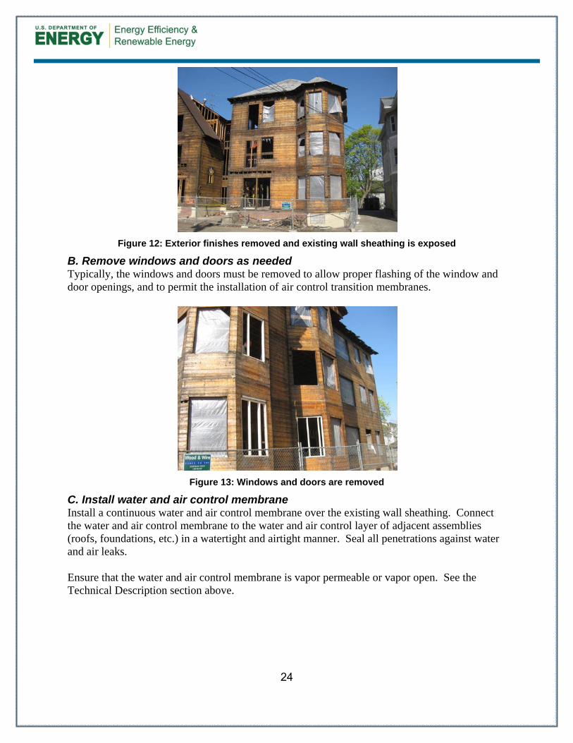
Figure 12: Exterior finishes removed and existing wall sheathing is exposed
B. Remove windows and doors as needed Typically, the windows and doors must be removed to allow proper flashing of the window and door openings, and to permit the installation of air control transition membranes.
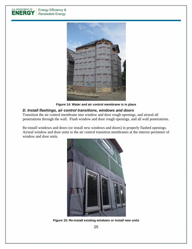
Figure 13: Windows and doors are removed
C. Install water and air control membrane Install a continuous water and air control membrane over the existing wall sheathing. Connect the water and air control membrane to the water and air control layer of adjacent assemblies (roofs, foundations, etc.) in a watertight and airtight manner. Seal all penetrations against water and air leaks. Ensure that the water and air control membrane is vapor permeable or vapor open. See the Technical Description section above.
25
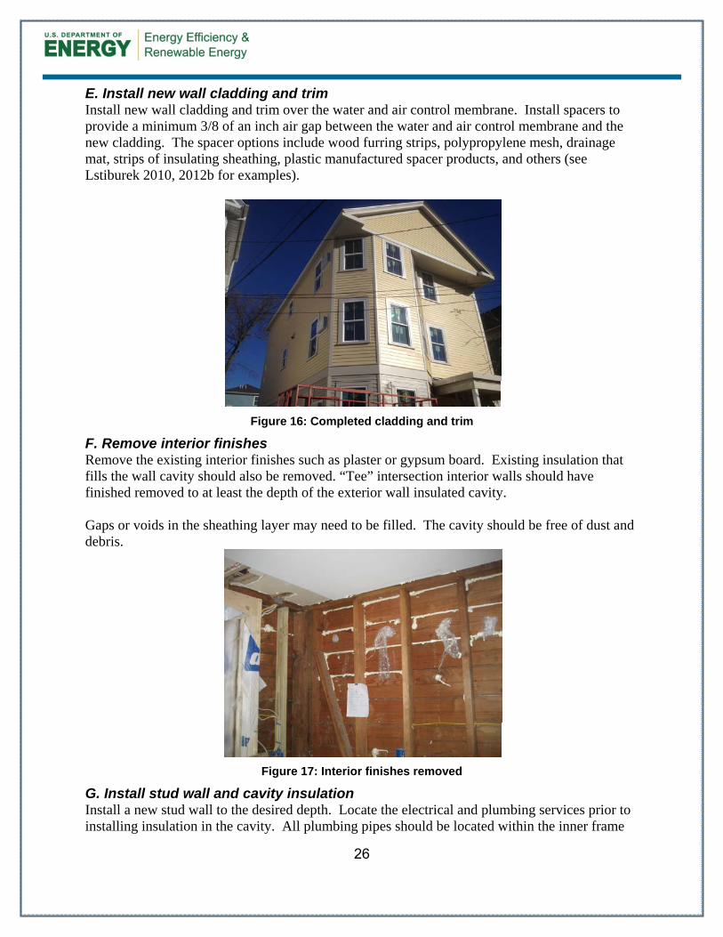
Figure 14: Water and air control membrane is in place
D. Install flashings, air control transitions, windows and doors Transition the air control membrane into window and door rough openings, and airseal all penetrations through the wall. Flash window and door rough openings, and all wall penetrations. Re-install windows and doors (or install new windows and doors) in properly flashed openings. Airseal window and door units to the air control transition membranes at the interior perimeter of window and door units.
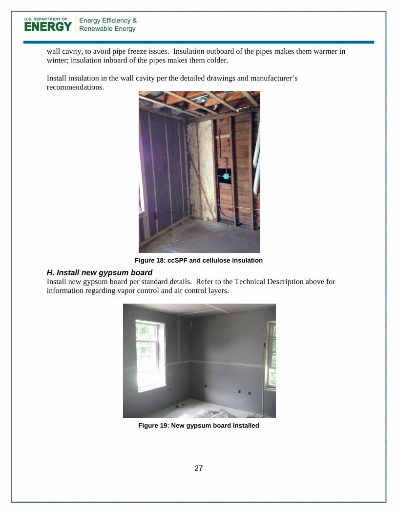
Figure 15: Re-install existing windows or install new units
26
E. Install new wall cladding and trim Install new wall cladding and trim over the water and air control membrane. Install spacers to provide a minimum 3/8 of an inch air gap between the water and air control membrane and the new cladding. The spacer options include wood furring strips, polypropylene mesh, drainage mat, strips of insulating sheathing, plastic manufactured spacer products, and others (see Lstiburek 2010, 2012b for examples).
Figure 16: Completed cladding and trim
F. Remove interior finishes Remove the existing interior finishes such as plaster or gypsum board. Existing insulation that fills the wall cavity should also be removed. “Tee” intersection interior walls should have finished removed to at least the depth of the exterior wall insulated cavity. Gaps or voids in the sheathing layer may need to be filled. The cavity should be free of dust and debris.
Figure 17: Interior finishes removed
G. Install stud wall and cavity insulation Install a new stud wall to the desired depth. Locate the electrical and plumbing services prior to installing insulation in the cavity. All plumbing pipes should be located within the inner frame
27
wall cavity, to avoid pipe freeze issues. Insulation outboard of the pipes makes them warmer in winter; insulation inboard of the pipes makes them colder. Install insulation in the wall cavity per the detailed drawings and manufacturer’s recommendations.
Figure 18: ccSPF and cellulose insulation
H. Install new gypsum board Install new gypsum board per standard details. Refer to the Technical Description above for information regarding vapor control and air control layers.
Figure 19: New gypsum board installed
28
Installation Procedure for Existing Cladding Option A. Retain existing wall cladding and trim Retain the existing wall cladding and trim. Repair the cladding as needed. The cladding may be affected depending on what type of cladding system is installed. See the Technical Description section above. B. Remove windows and doors as needed Typically, the windows and doors must be removed to allow proper flashing of the window and door openings, and to permit the installation of air control transition membranes. C. Install flashings, air control transitions, windows and doors Transition the air control layer into window and door rough openings, and airseal all wall penetrations. Flash window and door rough openings, and all wall penetrations. Re-install windows and doors (or install new windows and doors) in properly flashed openings. Airseal window and door units to the air control transition membranes at the interior perimeter of window and door units. D. Remove interior finishes Remove the existing interior finishes such as plaster or gypsum board. Existing insulation that fills the wall cavity should also be removed. Gaps or voids in the sheathing layer may need to be filled. The cavity should be free of dust and debris. E. Install stud wall and cavity insulation Install a new stud wall at the desired depth. “Tee” intersection interior walls should have finished removed to at least the depth of the exterior wall insulated cavity. Locate the electrical and plumbing services prior to installing insulation in the cavity. All plumbing pipes should be located within the inner frame wall cavity, to avoid pipe freeze issues. Insulation outboard of the pipes makes them warmer in winter; insulation inboard of the pipes makes them colder. Install insulation in the wall cavity per the detailed drawings and manufacturer’s recommendations. F. Install new gypsum board Install new gypsum board per standard details. Refer to the Technical Description above for information regarding vapor control and air control layers.
29
References
BSC (May 2009). "Info-401: Air Barriers—Airtight Drywall Approach". Building Science Corporation, http://www.buildingscience.com/documents/information-sheets/air-barriers-airtight-drywall-approach. Accessed May 18, 2011.
BSC (September 2009). "Info-408: Critical Seal (Spray Foam at Rim Joist)". Building Science Corporation, http://www.buildingscience.com/documents/information-sheets/critical-seal-spray-foam-at-rim-joist. Accessed January 27, 2015.
ICC (2009a). International Residential Code for One and Two –Family Dwellings. Country Club Hills, IL: International Code Council, Inc.
ICC (2009b). International Energy Conservation Code. Country Club Hills, IL: International Code Council, Inc.
ICC (2012a). International Residential Code for One and Two –Family Dwellings. Country Club Hills, IL: International Code Council, Inc.
ICC (2012b). International Energy Conservation Code. Country Club Hills, IL: International Code Council, Inc.
Lstiburek, J. (2006). Builder's Guide to Cold Climates. Westford, MA: Building Science Press.
Lstiburek, J. (2004). “Understanding Vapor Barriers.” ASHRAE Journal August 2004, Atlanta, Georgia: American Society of Heating Refrigeration and Air Conditioning Engineers. http://www.buildingscience.com/documents/digests/bsd-106-understanding-vapor-barriers/view
Lstiburek, J. (2008a). “Building Sciences: The Perfect Storm Over Stucco” ASHRAE Journal February 2008, Atlanta, Georgia: American Society of Heating Refrigeration and Air Conditioning Engineers. http://www.buildingscience.com/documents/insights/bsi-029-stucco-woes-the-perfect-storm
Lstiburek, J. (2008b). “Building Sciences: Energy Flow Across Enclosures” ASHRAE Journal August 2008, Atlanta, Georgia: American Society of Heating Refrigeration and Air Conditioning Engineers. http://www.buildingscience.com/documents/insights/bsi-028-energy-flow-across-enclosures/
Lstiburek, J. (2010). “Building Sciences: Mind the Gap, Eh!” ASHRAE Journal January 2010, Atlanta, Georgia: American Society of Heating Refrigeration and Air Conditioning Engineers. http://www.buildingscience.com/documents/insights/bsi-038-mind-the-gap-eh
Lstiburek, J. (2012a). Water Management Guide. Westford, MA: Building Science Press.
Lstiburek, J. (2012b). “Building Sciences: Hockey Pucks & Hydrostatic Pressure,” ASHRAE Journal January 2012, Atlanta, Georgia: American Society of Heating Refrigeration and Air Conditioning Engineers. http://www.buildingscience.com/documents/insights/bsi-057-hockey-pucks-and-hydrostatic-pressure/
30
Lstiburek, J. (2013). “Building Sciences: Macbeth Does Vapor Barriers (Double, Double Toil and Trouble).” ASHRAE Journal November 2013, Atlanta, Georgia: American Society of Heating Refrigeration and Air Conditioning Engineers. http://www.buildingscience.com/documents/ insights/bsi-073-macbeth-does-vapor-barriers/view
Maines, M. (2011). “Why Flash and Batt Makes Sense.” Fine Homebuilding Magazine, February/March 2011, pp. 60-63. Newtown, CT: Taunton Press.
Reed Construction Data. (2013). RSMeans CostWorks 2013, 17th Annual Edition. Norwell, MA. Retrieved November 7, 2014.
Straube, J.F. (2011). “Building Science Digest 163: Controlling Cold-Weather Condensation Using Insulation.” http://www.buildingscience.com/documents/digests/bsd-controlling-cold-weather-condensation-using-insulation/. Accessed January 2015.
Ueno, K.; Wytrykowska, H.; Bergey, D. (2013). Partnering to Build Net-Zero Energy Houses in Massachusetts. Accessed January 2015: http://www.buildingscience.com/documents/bareports/ba-1303-new-england-net-zero-new-construction-evaluations/view. Somerville, MA: Building Science Corporation.
Ueno, K. (2014). “Monitoring of Double Stud Wall Moisture Conditions in the Northeast.” August 2014. Washington, DC: Building America Building Technologies Program, Office of Energy Efficiency and Renewable Energy U.S. Department of Energy.
DOE/GO-000000-0000 ▪ Month Year
Printed with a renewable-source ink on paper containing at least 50% wastepaper, including 10% post-consumer waste.
Printed with a renewable-source ink on paper containing at l t 50% t i l di 10% t t
www.buildingamerica.gov
BA-1504: Deep Energy Enclosure Retrofit (DEER) for Double Stud Walls
Limits of Liability and Disclaimer of Warranty:
Building Science documents are intended for professionals. The author and the publisher of this article have used their best efforts to provideaccurate and authoritative information in regard to the subject matter covered. The author and publisher make no warranty of any kind,expressed or implied, with regard to the information contained in this article.
The information presented in this article must be used with care by professionals who understand the implications of what they are doing. Ifprofessional advice or other expert assistance is required, the services of a competent professional shall be sought. The author and publishershall not be liable in the event of incidental or consequential damages in connection with, or arising from, the use of the information containedwithin this Building Science document.
About this Report
This report was prepared with the cooperation of the U.S. Department of Energy’sBuilding America Program.
Direct all correspondence to: Building Science Corproation, 3 Lan Drive, Suite 102, Westford,MA 01886.
About the Authors
Honorata Loomis, LEED® AP, is an architectural designer and a project manager at Building ScienceCorporation. She works on a variety of new construction and retrofit building projects including residential,commercial and institutional. She is also involved in conducting building failure investigations and performancetesting as well as production of BSC publications.
Betsy Pettit, FAIA, is the president of Building Science Corporation and is a registered architect with over 30 years of professional experience. She is currently the project manager for Building Science Corporation's Building America project that has provided whole system designs for over 3,000 high performance houses nationwide.


![Welcome [] · 2019. 1. 14. · Highgate West Meadow Pryors Field Bandstand Playground and Paddling Pool Playpark (Adventure Playground Deer Enclosure Animal Enclosure Prospect Hill](https://static.documents.pub/doc/80x56/5fff1202f803d87dfa524301/welcome-2019-1-14-highgate-west-meadow-pryors-field-bandstand-playground.jpg)

