94
COMBUSTION AND FUELS MEASUREMENT METHODS IN COMBUSTION PROCESSES
| Date post: | 28-Jul-2018 |
| Category: |
Documents |
| Upload: | truongcong |
| View: | 215 times |
| Download: | 0 times |

COMBUSTION AND FUELS
MEASUREMENT METHODS IN COMBUSTION PROCESSES
COMBUSTION AND FUELS
Major aim of combustion diagnostics
1. Cognitive (knowledge extension on combustion
processes)
2. Practical
a) improvement of combustion effectiveness in
furnaces
b) abatement of pollutant emissions
c) improvement of control of combustion
processes
COMBUSTION AND FUELS
Subjects of combustion diagnostics
1. Flames
a) flame zone
b) after-flame zone
2. Combustion gases (composition, pollutants)
3. Solid furnace’s residues
a) fly ash, bottom ash (content, slagging)
b) properties (sizing, toxicity, solubility,
unburned coal)
COMBUSTION AND FUELS
Measured parameters of combustion processes
1. Temperature (in flame, of combustion gases, its
pulsations)
2. Content of flue gases (radicals, stable molecules,
solid particles)
3. Radiation
4. Flow velocities (turbulence)
Measurements made in a point and distributions
COMBUSTION AND FUELS
FLAME DIAGNOSTICS

COMBUSTION AND FUELS
TEMPERATURE MEASUREMENTS
IN FLAME
COMBUSTION AND FUELS
Flame characteristic
1. Flame is highly reactive environment, often far from
equilibrium
2. Flames are characterized by high temperatures and
great gradients of temperature
3. Accuracy of measurement of the temperature in flame
depends not only on the selected method of
measurement, but also on: the type of flame, sort of
fuel, turbulence and radiation of flame.
COMBUSTION AND FUELS
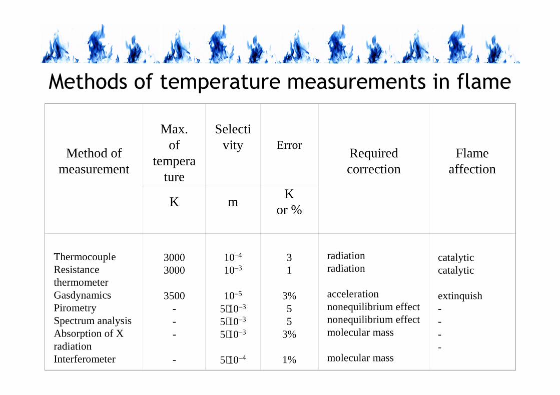
Methods of temperature measurements in flame
Method of measurement
Max. of
temperature
Selectivity Error
Required correction
Flame affection
K mK
or %
ThermocoupleResistance thermometer GasdynamicsPirometrySpectrum analysisAbsorption of X radiationInterferometer
30003000
3500---
-
10–4
10–3
10–5
5⋅10–3
5⋅10–3
5⋅10–3
5⋅10–4
31
3%55
3%
1%
radiationradiation
accelerationnonequilibrium effectnonequilibrium effectmolecular mass
molecular mass
catalyticcatalytic
extinquish----
COMBUSTION AND FUELS
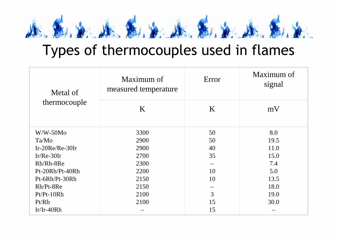
Types of thermocouples used in flames
Metal ofthermocouple
Maximum of measured temperature
ErrorMaximum of
signal
K K mV
W/W-50MoTa/MoIr-20Re/Re-30IrIr/Re-30IrRh/Rh-8RePt-20Rh/Pt-40RhPt-6Rh/Pt-30RhRh/Pt-8RePt/Pt-10RhPt/RhIr/Ir-40Rh
3300290029002700230022002150215021002100
–
50504035–1010–31515
8.019.511.015.07.45.013.518.019.030.0
–
COMBUSTION AND FUELS
Errors associated with temperature
measurement in flame
A thermocouple introduced inserted into flame shows
the temperature different from flame temperature
because of:
• catalytic effect,
• aerodynamic effect,
• heat conduction by thermocouple’s wires,
• radiation of a thermocouple.

COMBUSTION AND FUELS
Correction of error resulted from radiation:
method of two thermocouples
Scheme of double thermocouple: 1 – thermocouples Pt-RhPt,
2 – thermocouple measuring the temperature of free ends of
thermocouple 1,
d1, d2 – diameters of thermocouple’s joins
)(
)(1
42
41
5,0
1
2
212
4ot
4ot
pl
TT
TT
d
d
TTTT
−−
−
−+= −

COMBUSTION AND FUELS
Optical methods of
temperature measurements
in flames

COMBUSTION AND FUELS
Method of reversed spectral lines (of sodium)
1 – reference lamp,2 – lens,3 – screen, 4 – flame,5 – spectroscope, 6 – solution of NaCl, 7 – electric arc,8 – NaCl filter, 9 – mixer, 10 – burner.
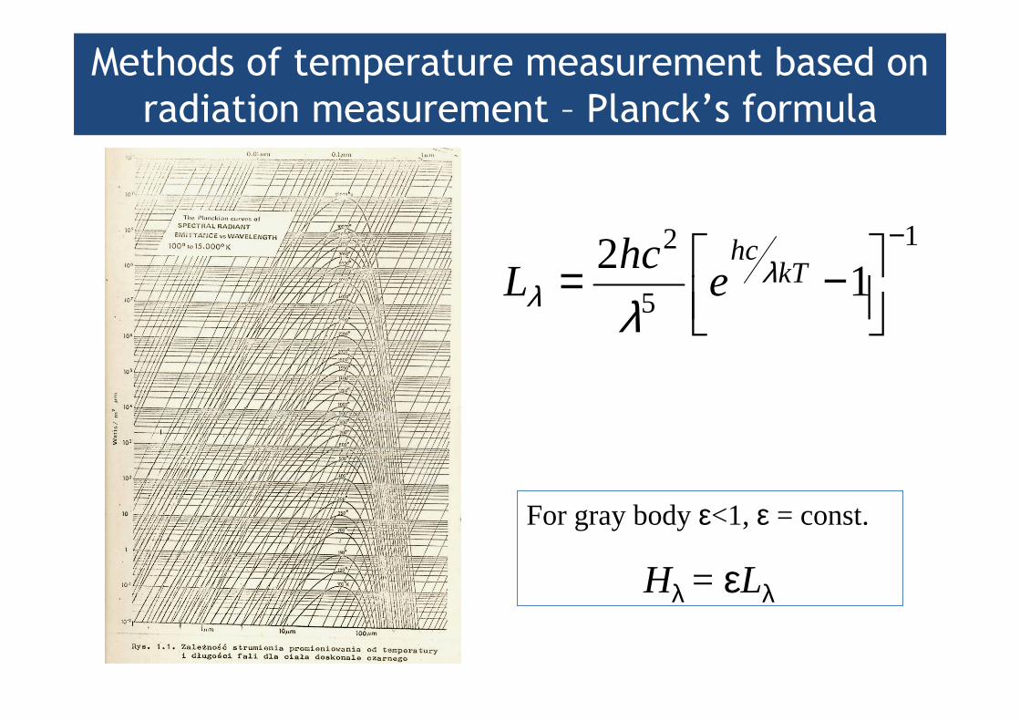
Methods of temperature measurement based on
radiation measurement – Planck’s formula
1
5
2
12 −
−= kThc
ehc
L λλ λ
For gray body ε<1, ε = const.
Hλ = εLλ

COMBUSTION AND FUELS
Single colour pyrometer
Manufacturer:
Raytec

COMBUSTION AND FUELS
Two colour pyrometer – principle of
temperature measurement
BE
EA
T+
=
2
1
pl
ln1
λ
λ
For gray bodyε<1, ε = const.
Hλ = εLλ

COMBUSTION AND FUELS
Two colour pyrometerSchem
e o
f optics

COMBUSTION AND FUELS
MEASUREMENTS OF SPECIES
CONCENTRATIONS IN FLAMES
COMBUSTION AND FUELS
Types of reactants in flames
1. Stable: long lifetime, easy to separate and analyse(molecules of fuel, oxidizer and products of oxidation, e.g. O2,
N2, CH4, CO2 H2O,..,). Their concentrations are large, from a
few to several tens percents of volume.
2. Unstable: short lifetime, difficult to separate (undergo
termination on the wall of a probe. They are radicals (O, H,
OH, CH3 ...) and ions. Their concentration in flame is low
10-6 ÷ 10-15 %).
3. Excited molecules (e.g. CO2*...)
COMBUSTION AND FUELS
Sampling of species in flames
Sampling in flames can be made in two ways:
1. Izokinetic sampling (subsonic), to prevent
separation of particles (mainly solids)
2. Ultrasonic sampling with freezing of a sample.

Isokinetic probe for suction of components in gaseous flame

COMBUSTION AND FUELS
Supersonic „freezing” probe for suction of gas
components in gaseous flame
Filter made of
sintered bronze
Quartz
tube

COMBUSTION AND FUELS
Gas chromatography
1. Gas chromatography is a method of separation and
detection of chemical compounds in gaseous mixtures.
2. Separation of components of a mixture occurs on the
boundary of phases:
a. solid (fixed),
b. gaseous (gas carrying a sample)
3. A sample carried by gas through a column (steel pipe
filled with an adsorbent) undergoes adsorption and
desorption.

COMBUSTION AND FUELS
Scheme of chromatograph
1 – container with carrying gas, 2 – flow rate controller, 3 – samples injector, 4 – thermostatic chromatographic column, 5 – temperature controller, 6 – detector,
7 – amplifier, 8 - recorder, 9 – integrator
COMBUSTION AND FUELS
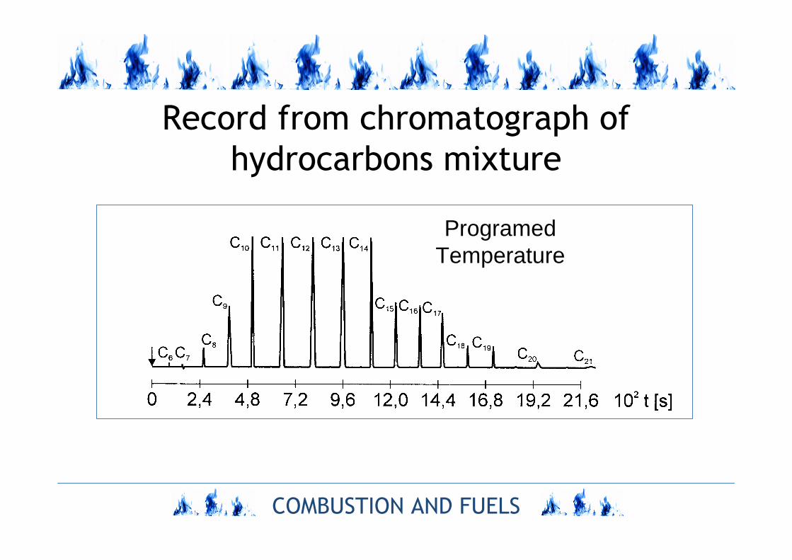
Record from chromatograph of
hydrocarbons mixture
ProgramedTemperature
COMBUSTION AND FUELS
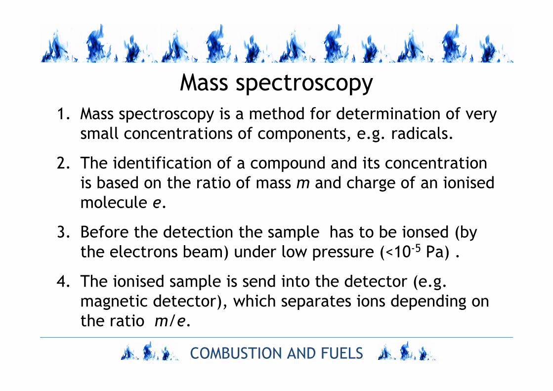
Mass spectroscopy
1. Mass spectroscopy is a method for determination of very
small concentrations of components, e.g. radicals.
2. The identification of a compound and its concentration
is based on the ratio of mass m and charge of an ionised
molecule e.
3. Before the detection the sample has to be ionsed (by
the electrons beam) under low pressure (<10-5 Pa) .
4. The ionised sample is send into the detector (e.g.
magnetic detector), which separates ions depending on
the ratio m/e.
COMBUSTION AND FUELS
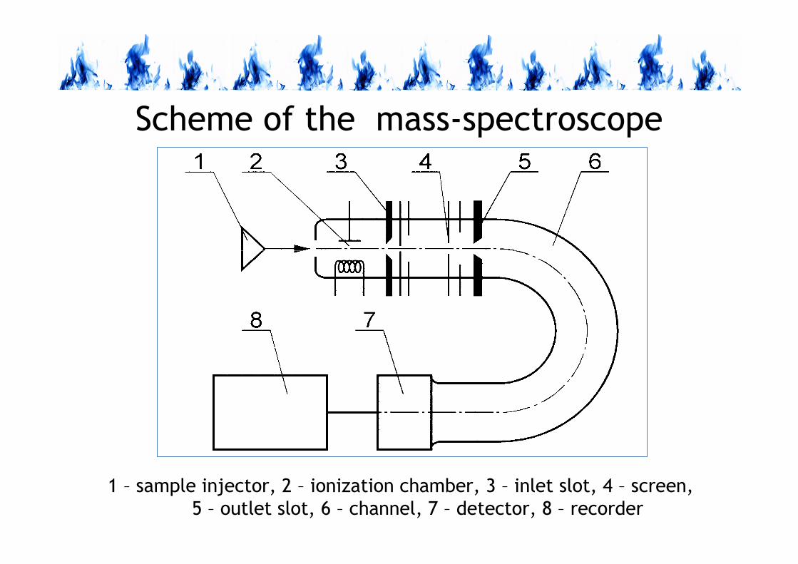
Scheme of the mass-spectroscope
1 – sample injector, 2 – ionization chamber, 3 – inlet slot, 4 – screen,
5 – outlet slot, 6 – channel, 7 – detector, 8 – recorder

COMBUSTION AND FUELS
Spectroscopy1. The identification of chemical compounds is based on the
analysis of the spectrum of emission and absorption of
electromagnetic radiation of a sample.
2. In the visible and ultraviolet range emission and absorption of
radiation results in the change of electron states. And, in the
range of infrared radiation, it is the result of the change of
oscillatory-vibration energy of a molecule.
3. The spectrum of radiation is composed of atomic lines,
molecular bands and the continuous spectrum.
4. Radiation of chemical elements and compounds is concentrated
in characteristic lines and bands and is used for their detection.
5. A source of excitation (emission) is flame temperature and
chemical reactions.

COMBUSTION AND FUELS
EPR spectroscopy
Spectroscopy of electron resonance (EPR) is used for
the detection of spines in paramagnetic free radicals,
therefore it has found application in the detection
and determination of the concentration of radicals in
flames.

COMBUSTION AND FUELS
Raman spectroscopy
1. The development of lasers as the monochromatic sources of
light has given a basis for the development of many non-
invasive methods of investigations in combustion chemistry.
2. The identification of a chemical compound is based on the
dispersion of weak radiation emitted by a molecule and
induced by laser radiation.
3. The result of a laser excitation is Rayleigh dispersion and
Raman, Stocks and unti-stocks dispersion
4. During flame investigation the CARS is often used – together
with the use of compact anti-Stocks Raman dispersion.

COMBUSTION AND FUELS
Scheme of Raman spectrometer
1 – laser, 2 – primary optics, 3 – mirror, 4 – cuvette, 5 – depolarizer,
6 – monochromator, 7 – diffraction mesh, 8 – interference filter,
9 –photomultiplier, 10 – amplifier, 11 – recorder
COMBUSTION AND FUELS
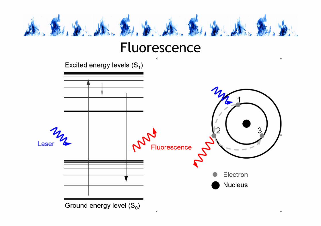
LIF (Laser Induced- Fluorescence)
spectroscopy
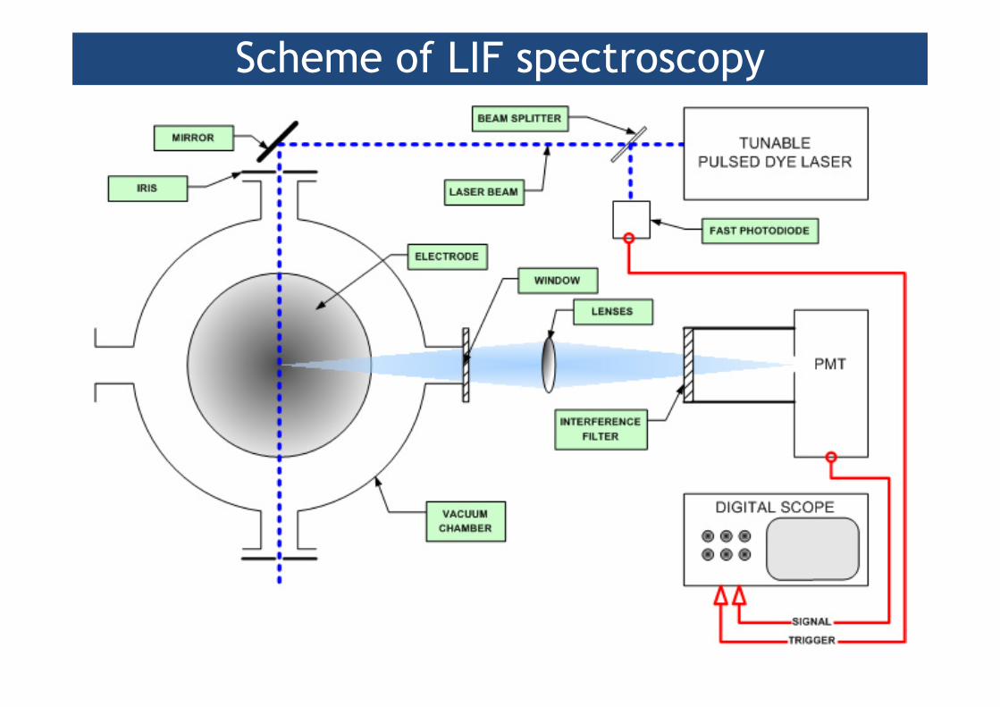
Scheme of LIF spectroscopy

COMBUSTION AND FUELS
PLIF (Planar Laser-Induced Fluorescence) spectroscopy
1. PLIF is an optical method of diagnosis for visualization and
measurement processes in flow.
2. It can be applied for the determination of space
distribution of concentrations, temperature, velocity and
pressure in gas.
3. The main components of PLIF area: laser, optics,
fluorescence medium and detection system.
4. Light excites the medium, which radiate (fluorescence).
This signal is received by the detector and is used for the
determination of different properties of medium.
COMBUSTION AND FUELS
Fluorescence

COMBUSTION AND FUELS
Example of PLIF application

COMBUSTION AND FUELS
Measurement of ions and electrons in flame
1. The problem concerns the measurement of ions and
electrons in flame and their spatial distribution.
2. Most often the concentration of ions and electrons in
flame is measured using Langmuira’s probe.
3. Ions concentration can be measured using mass
spectroscopy.
COMBUSTION AND FUELS
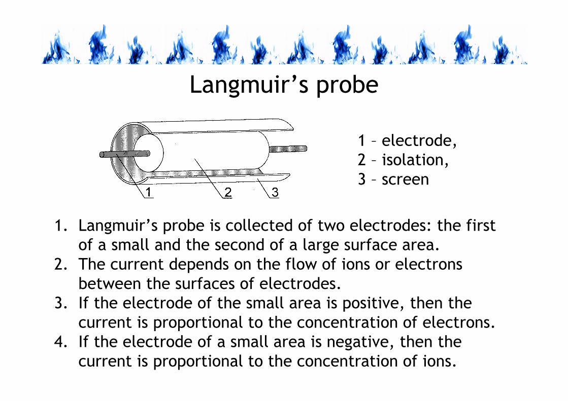
Langmuir’s probe
1 – electrode,
2 – isolation,
3 – screen
1. Langmuir’s probe is collected of two electrodes: the first
of a small and the second of a large surface area.
2. The current depends on the flow of ions or electrons
between the surfaces of electrodes.
3. If the electrode of the small area is positive, then the
current is proportional to the concentration of electrons.
4. If the electrode of a small area is negative, then the
current is proportional to the concentration of ions.
COMBUSTION AND FUELS
FLAME DETECTORS
COMBUSTION AND FUELS
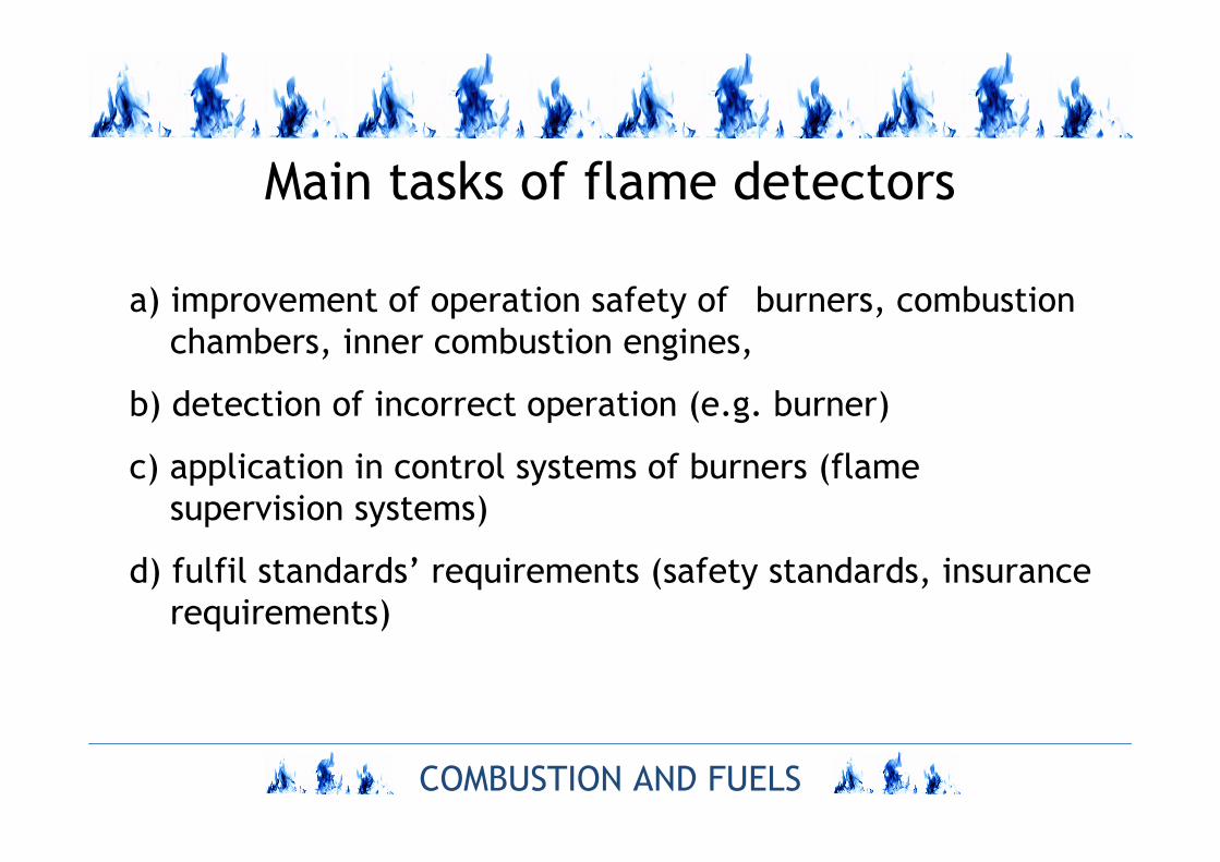
Main tasks of flame detectors
a) improvement of operation safety of burners, combustion
chambers, inner combustion engines,
b) detection of incorrect operation (e.g. burner)
c) application in control systems of burners (flame
supervision systems)
d) fulfil standards’ requirements (safety standards, insurance
requirements)
COMBUSTION AND FUELS
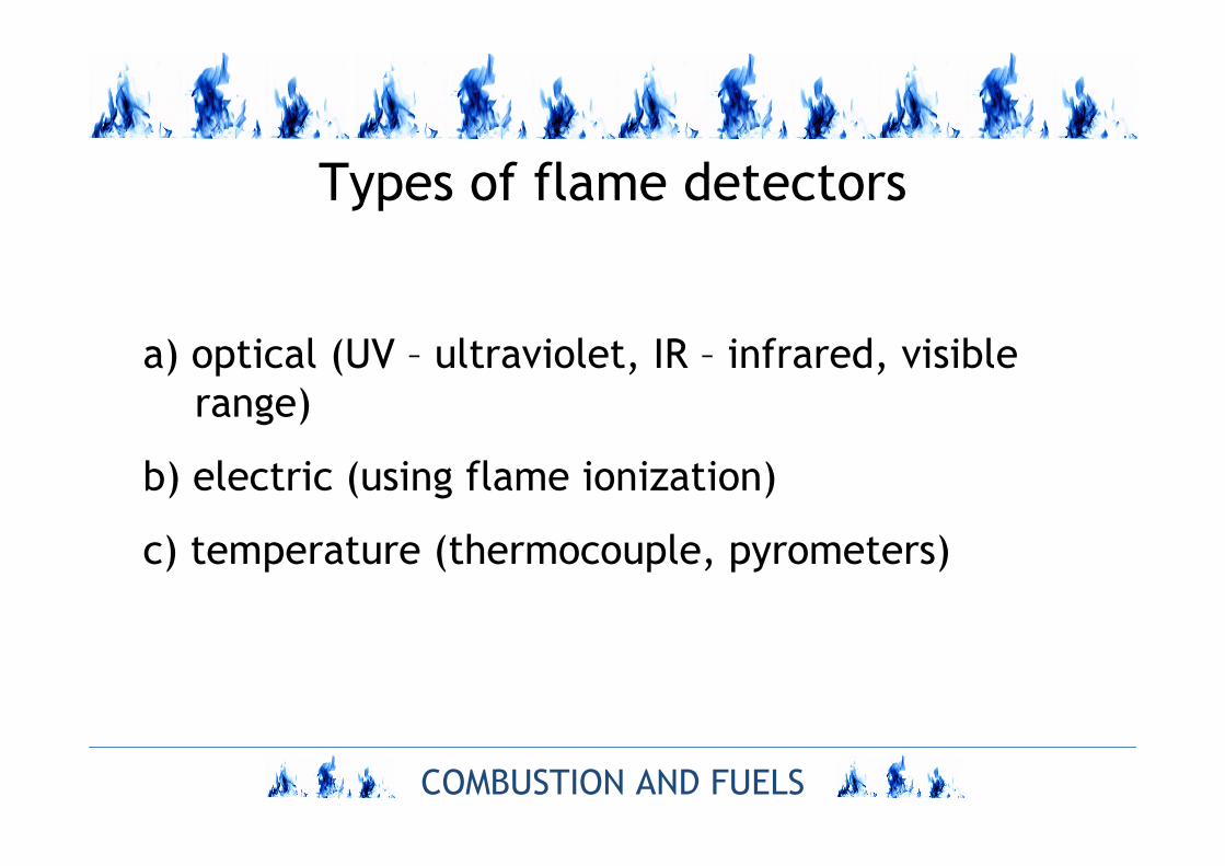
Types of flame detectors
a) optical (UV – ultraviolet, IR – infrared, visible
range)
b) electric (using flame ionization)
c) temperature (thermocouple, pyrometers)
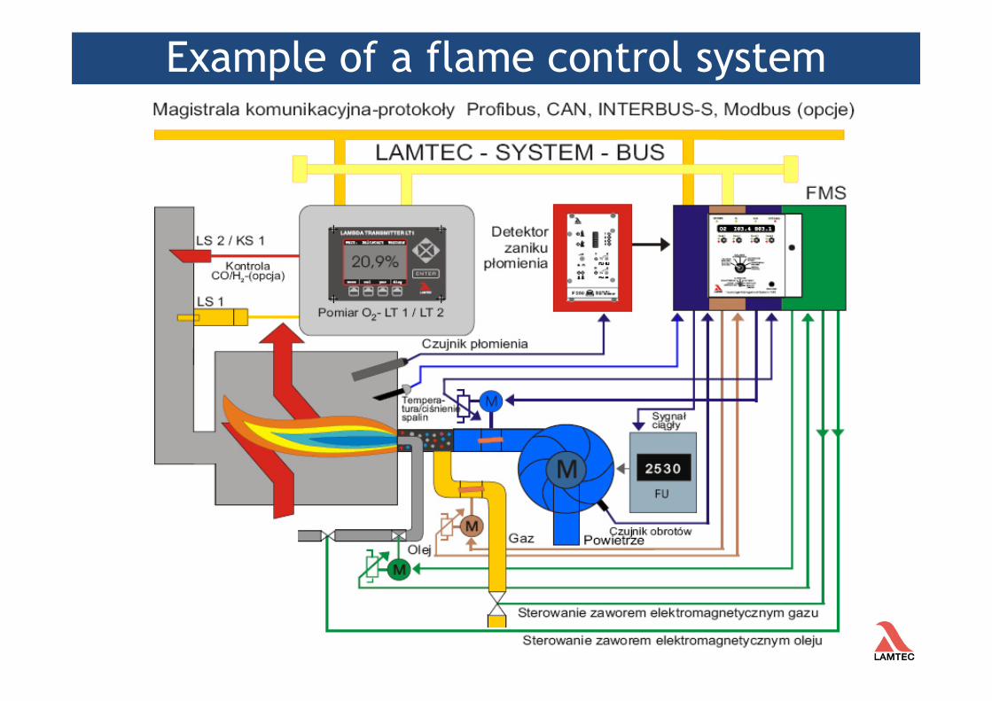
Example of a flame control system
COMBUSTION AND FUELS
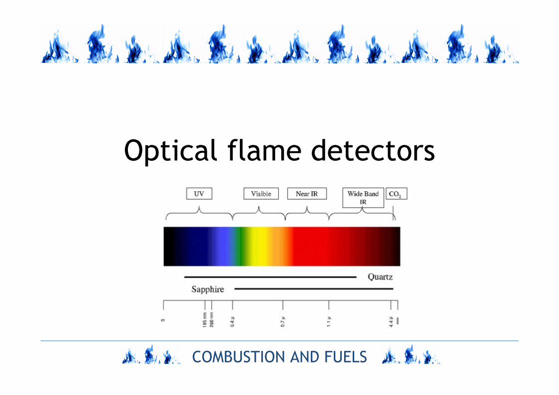
Optical flame detectors
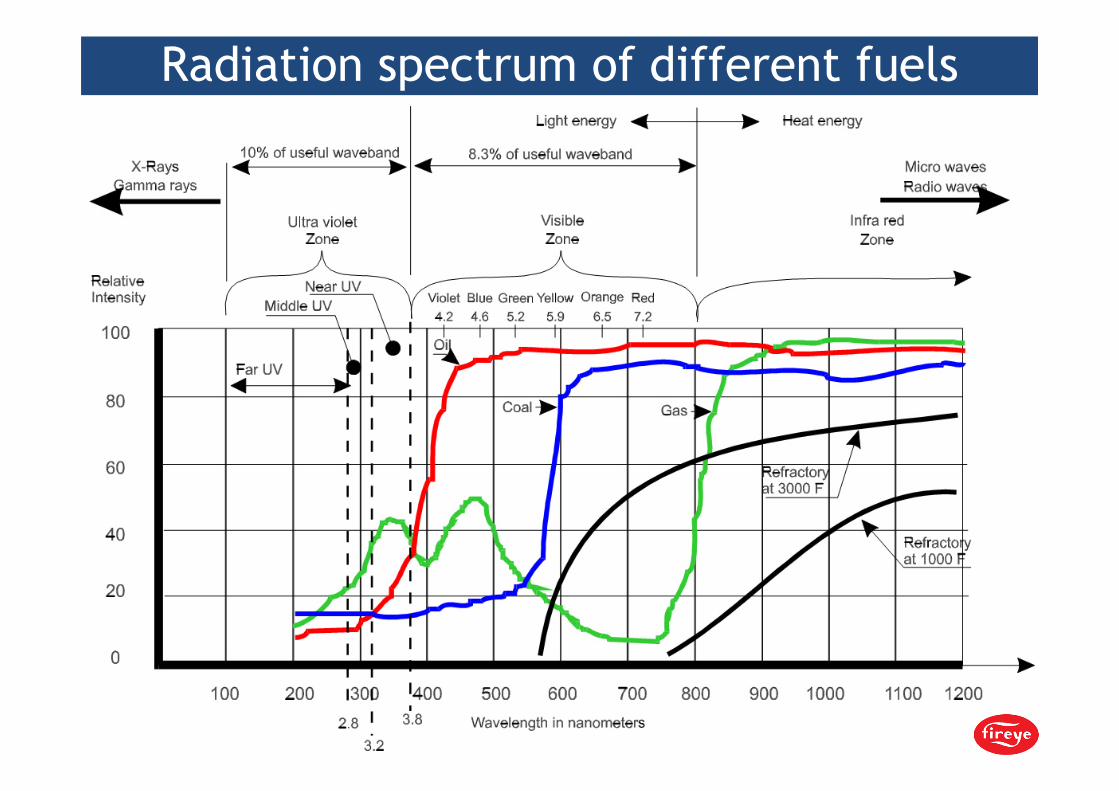
Radiation spectrum of different fuels

Criteria of flame detectors selection
detectors

COMBUSTION AND FUELS
Criteria of flame detectors selection

COMBUSTION AND FUELS
UV sensors
Types of ultraviolet (UV) flame detectors:
a) UV vacuum tube detectors
b) UV semiconductor detectors

COMBUSTION AND FUELS
Radiation of gaseous flame
99%
infraredvisible
lightUV
max 1/3 of
flame length
<1% of
radiation
<10% of
radiation
90% of
radiation
1%
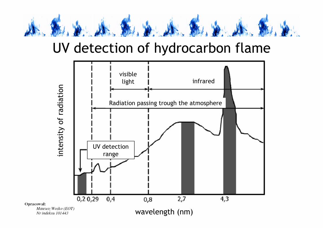
COMBUSTION AND FUELS
infraredvisible
light
UV detection
range
wavelength (nm)
inte
nsity
ofra
dia
tion
Radiation passing trough the atmosphere
UV detection of hydrocarbon flame

COMBUSTION AND FUELS
Vacuum UV detector tubes
Quartz tube with two electrodes
is filled with gas. UV radiation
activates cathode plate which
produces electrons initiating gas
ionisation.
Voltage between the electrodes
is in the range 75-200 V.
Types of disturbances of UV detectors:
- ignition spark,- welding arc,- halogen light,- hot furnace walls (>1200 oC)
electrodes quartz tube
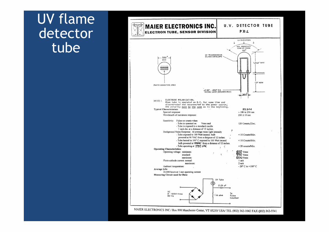
UV flame detector
tube
COMBUSTION AND FUELS
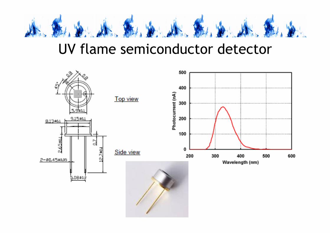
UV flame semiconductor detector
COMBUSTION AND FUELS
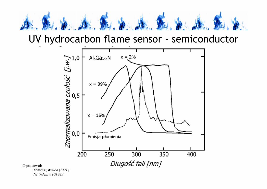
UV hydrocarbon flame sensor - semiconductor
(nitrate)
COMBUSTION AND FUELS
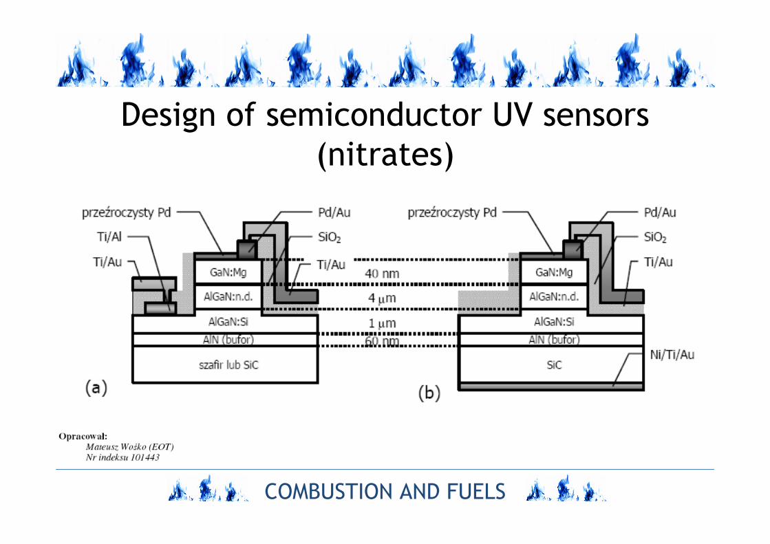
Design of semiconductor UV sensors
(nitrates)
COMBUSTION AND FUELS
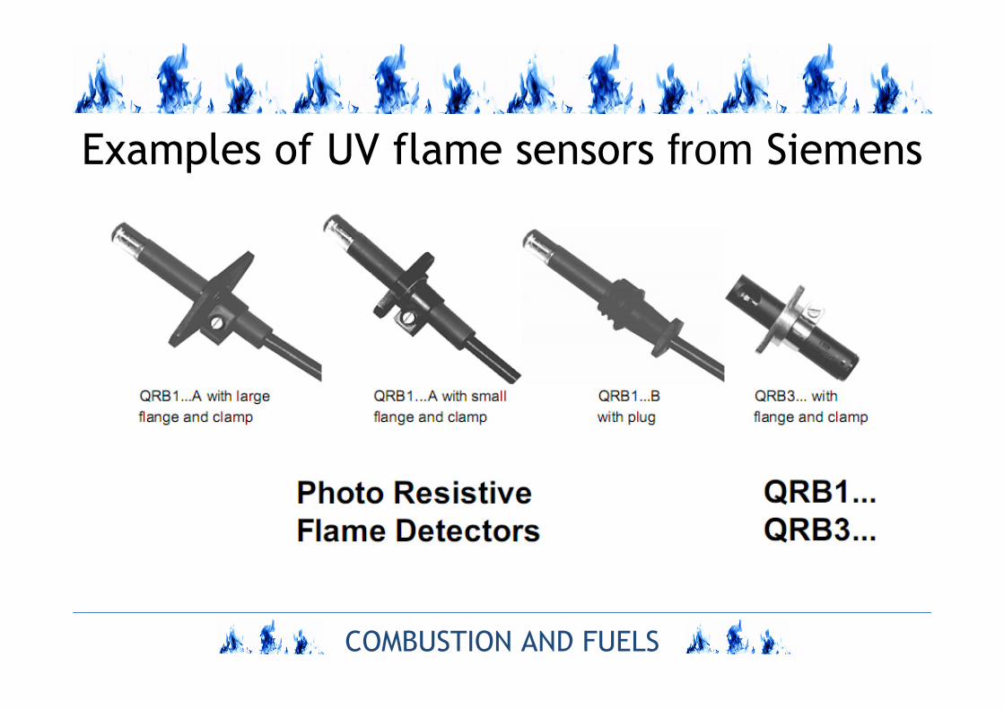
Examples of UV flame sensors from Siemens

UV flame detector
(Lamtec F 200 K Ex Compact Flame Detector)
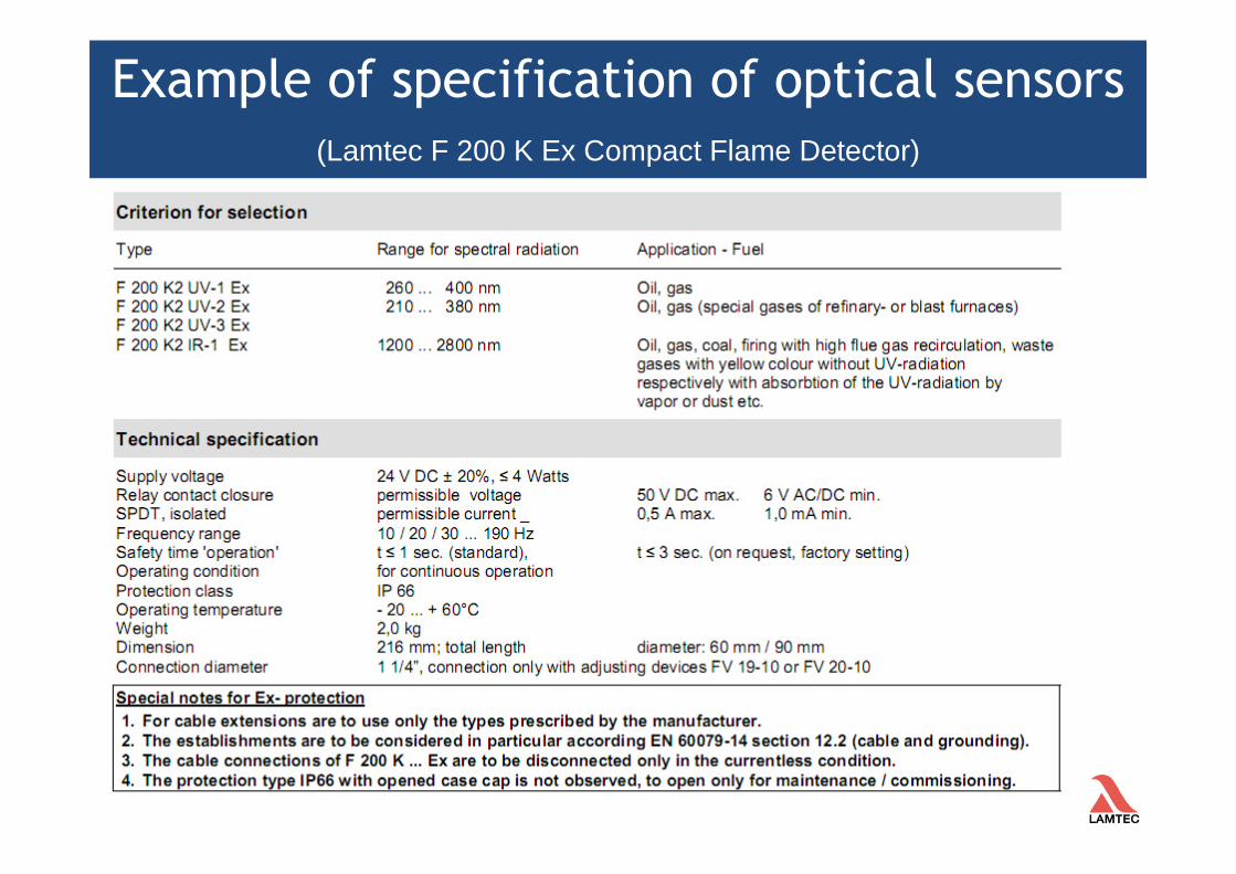
Example of specification of optical sensors
(Lamtec F 200 K Ex Compact Flame Detector)
COMBUSTION AND FUELS
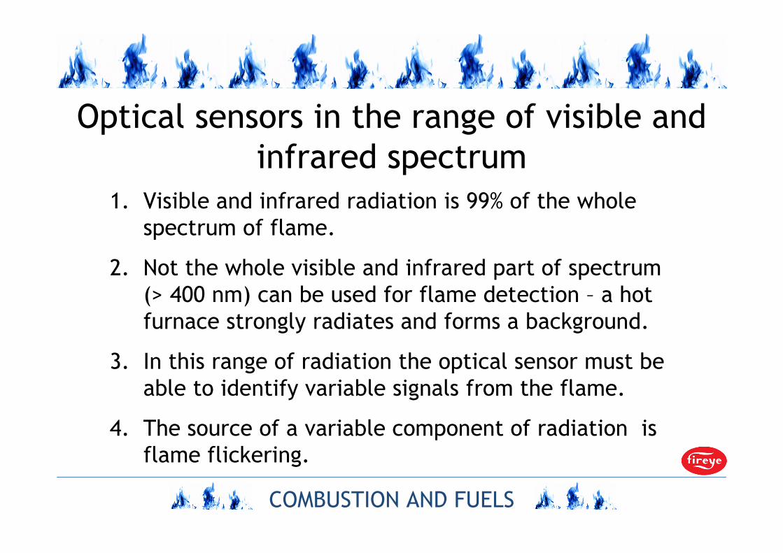
Optical sensors in the range of visible and
infrared spectrum
1. Visible and infrared radiation is 99% of the whole
spectrum of flame.
2. Not the whole visible and infrared part of spectrum
(> 400 nm) can be used for flame detection – a hot
furnace strongly radiates and forms a background.
3. In this range of radiation the optical sensor must be
able to identify variable signals from the flame.
4. The source of a variable component of radiation is
flame flickering.

COMBUSTION AND FUELS
Comparison of photodetector (PbS resistor) signals
from solid body and flame radiation
COMBUSTION AND FUELS
FLAME SCANNERS

COMBUSTION AND FUELS
Flame scanners
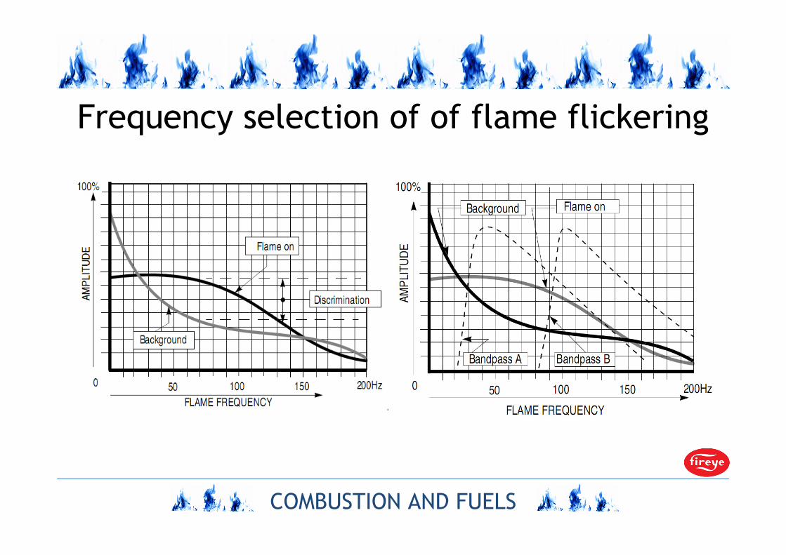
1. Flame scanners are called flame detectors (in the visible
and IR range); they are equipped with the identification
system of a radiation component characteristic of a
superintendent flame.
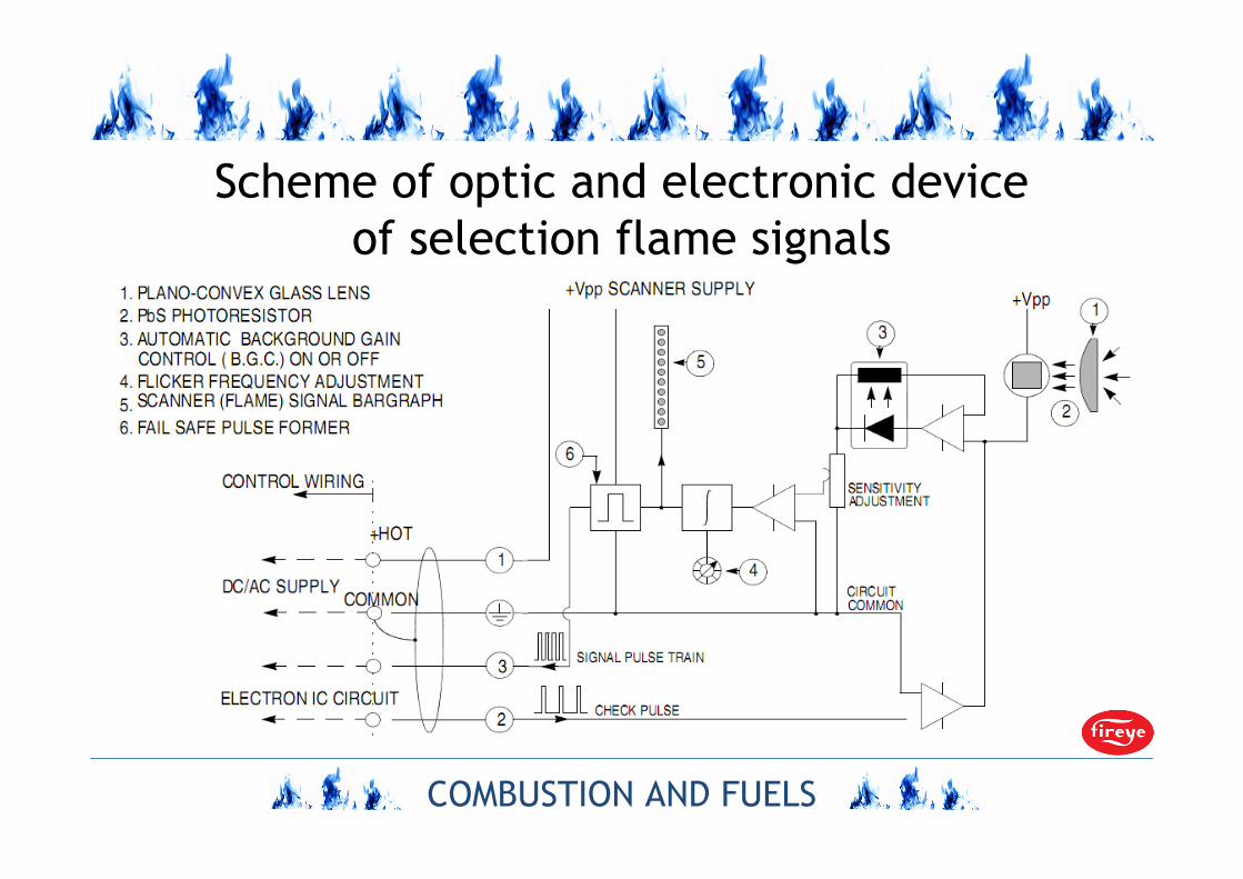
2. The flame scanner is composed of optics (lens), IR sensor,
te signal amplifier and the frequency selector.
3. The typical optical flame sensors in the visible and IR
range are photoresistors (e.g. PbS) and photodiodes (e.g.
InGaAs).
COMBUSTION AND FUELS
Frequency selection of of flame flickering
COMBUSTION AND FUELS
Scheme of optic and electronic device
of selection flame signals
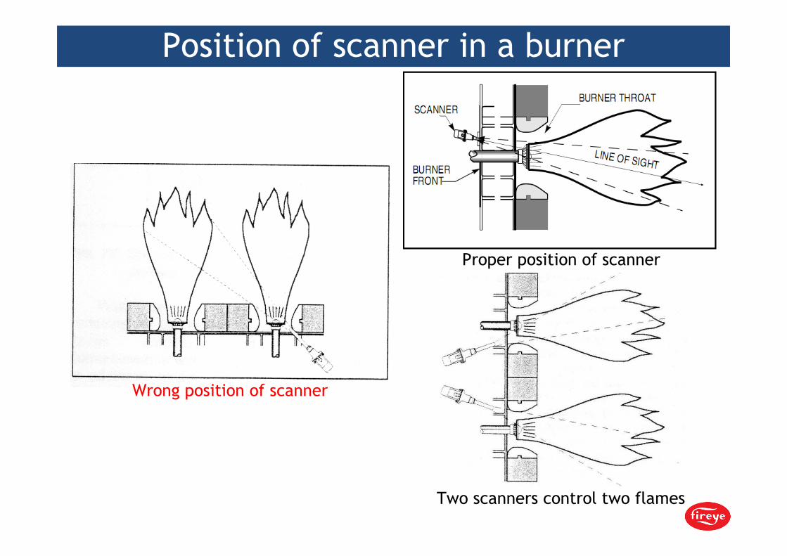
Position of scanner in a burner
Wrong position of scanner
Proper position of scanner
Two scanners control two flames

Amplitude- frequency characteristic of flame flickering
Wg. mat. firmy AC System sp. z o.o.
low amplitudehigh frequency
high amplitudelow frequency
low flickering frequency
high flickering frequency
amplitude(dB)
amplitude(dB) measurement
points
approximation line
FAST FOURIER TRANSFORM
time (s) frequency (Hz)

COMBUSTION AND FUELS
Application of optics fibres in scanners

COMBUSTION AND FUELS
Infrared flame scanner (Fireye)
COMBUSTION AND FUELS
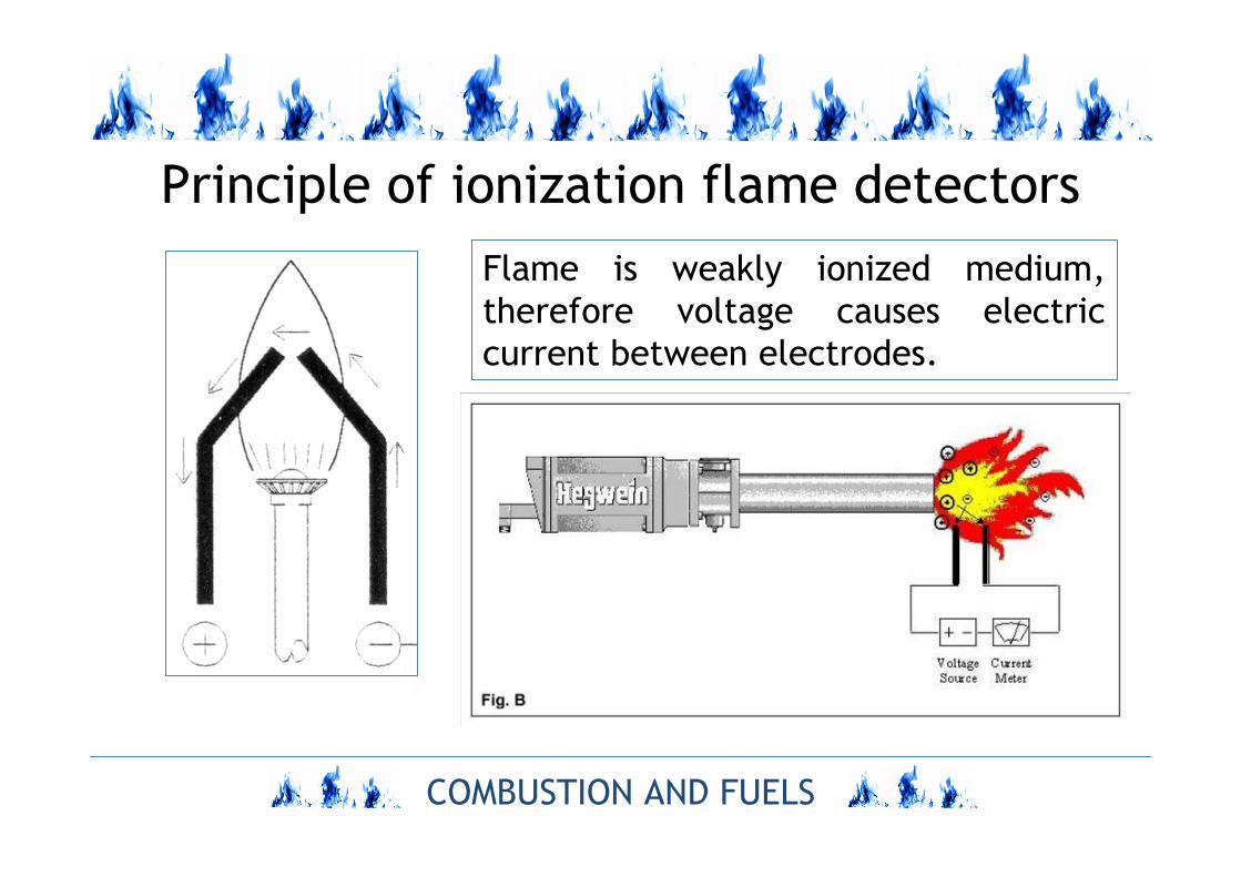
Principle of ionization flame detectors
Flame is weakly ionized medium,
therefore voltage causes electric
current between electrodes.
COMBUSTION AND FUELS
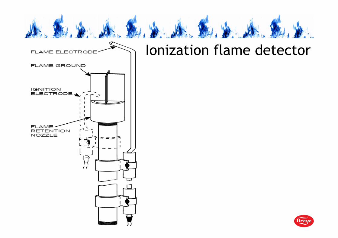
Ionization flame detector
COMBUSTION AND FUELS
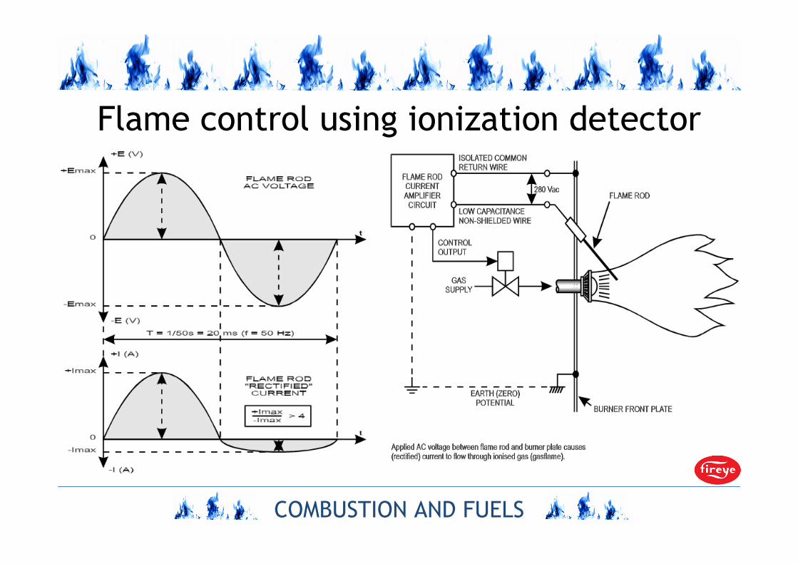
Flame control using ionization detector

COMBUSTION AND FUELS
STECHIOMETRY OF
COMBUSTION CONTROL
IN FURNACES
COMBUSTION AND FUELS
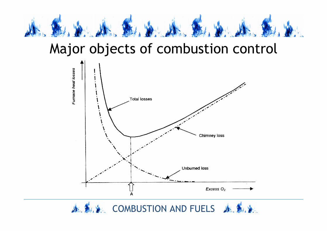
Major objects of combustion control

COMBUSTION AND FUELS
Simple control of air excess in furnace

COMBUSTION AND FUELS
Boiler’s lambda sensor

Stoichiometry control by measurement of oxygen
concentration in flue gas using zirconia λ probe
Flue gas channel
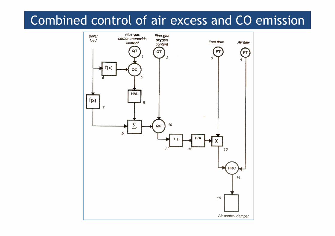
Combined control of air excess and CO emission

Air excess control when two types of fuels are burnt
COMBUSTION AND FUELS
DIAGNOSTICS OF
CORROSION HAZARD IN
PULVERIZED COAL
FURNACES
COMBUSTION AND FUELS
Methods of corrosion hazard diagnostics
1. Periodic
2. Continuous and quasi-continuous (on-line)
COMBUSTION AND FUELS
Periodic diagnostics of corrosion hazard
1. Control of water-tube’s thickness losses
2. Measurements of boundary layer content

COMBUSTION AND FUELS
Periodic control of thickness losses of
evaporator watertubes
a. Supersonic
b. EMAT (Electromagnetic Acoustic Transducer)
c. Infrared (IR)
d. Collecting and testing of watertube’s samples

COMBUSTION AND FUELS
Supersonic method of measurement of
watertube thickness

COMBUSTION AND FUELS
Measurement of watertube thickness by EMAT
COMBUSTION AND FUELS
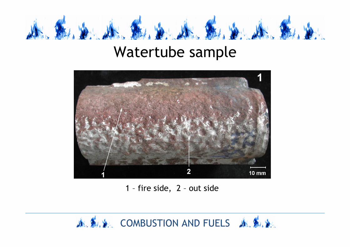
Watertube sample
1 – fire side, 2 – out side
COMBUSTION AND FUELS
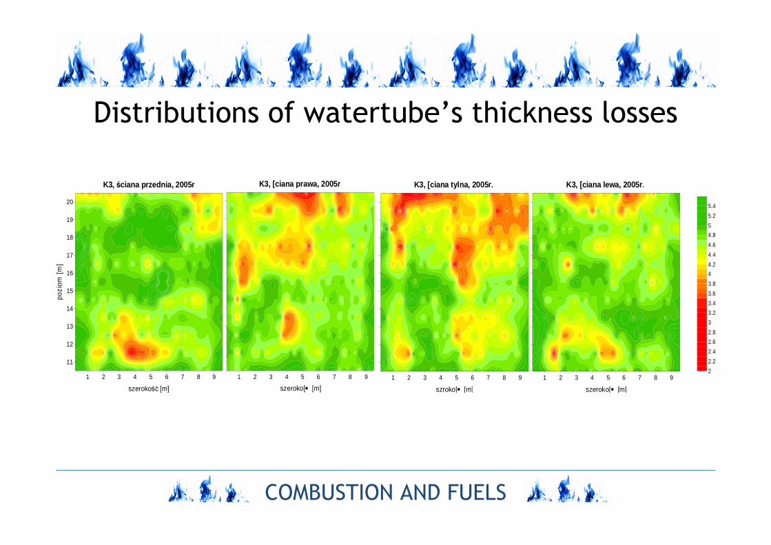
Distributions of watertube’s thickness losses
1 2 3 4 5 6 7 8 9
szerokość [m]
K3, ściana przednia, 2005r
11
12
13
14
15
16
17
18
19
20
pozi
om [
m]
2
2.2
2.4
2.6
2.8
3
3.2
3.4
3.6
3.8
4
4.2
4.4
4.6
4.8
5
5.2
5.4
1 2 3 4 5 6 7 8 9
�szeroko[ [m]
K3, [ciana prawa, 2005r
1 2 3 4 5 6 7 8 9
�szroko[ [m]
K3, [ciana tylna, 2005r.
1 2 3 4 5 6 7 8 9
�szeroko[ [m]
K3, [ciana lewa, 2005r.
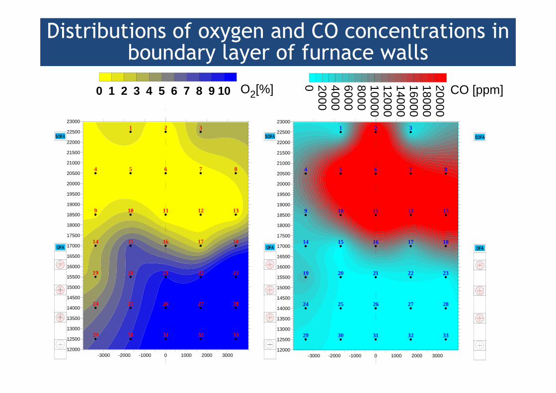
Distributions of oxygen and CO concentrations in boundary layer of furnace walls
1 2 3
4 5 6 7 8
9 10 11 12 13
14 15 16 17 18
19 20 21 22 23
24 25 26 27 28
29 30 31 32 33
-3000 -2000 -1000 0 1000 2000 300012000
12500
13000
13500
14000
14500
15000
15500
16000
16500
17000
17500
18000
18500
19000
19500
20000
20500
21000
21500
22000
22500
23000
SOFA
OFA
SOFA
OFA
0 1 2 3 4 5 6 7 8 9 10 O2[%]
1 2 3
4 5 6 7 8
9 10 11 12 13
14 15 16 17 18
19 20 21 22 23
24 25 26 27 28
29 30 31 32 33
-3000 -2000 -1000 0 1000 2000 300012000
12500
13000
13500
14000
14500
15000
15500
16000
16500
17000
17500
18000
18500
19000
19500
20000
20500
21000
21500
22000
22500
23000
SOFA
OFA0 2000400060008000100001200014000160001800020000
CO [ppm]
COMBUSTION AND FUELS
Continuous and quasi-continuous methods of
corrosion hazard diagnostics
a. Measurement of electric resistance of watertubes of
evaporator
b. Corrosion probes ENM (Electrochemical Noise Analysis)
c. Corrosion probes based on measurement of resistance
of probe
d. Corrosion probes based on loss of testing tube.
COMBUSTION AND FUELS
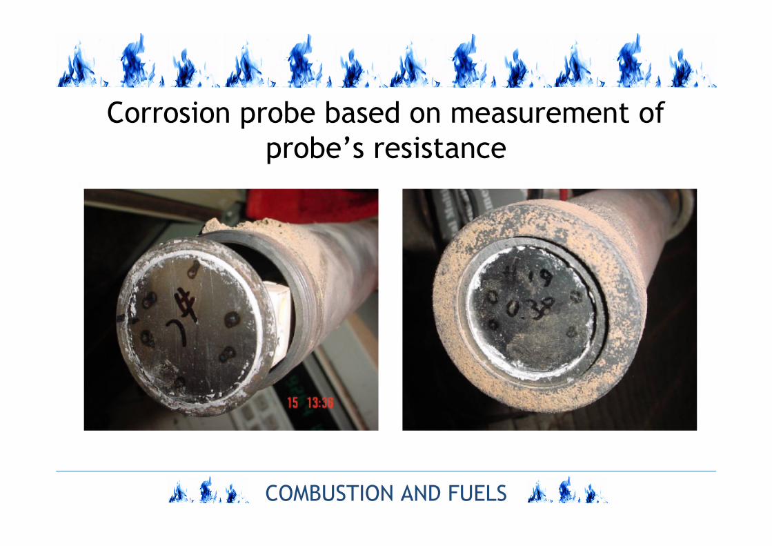
Corrosion probe based on measurement of
probe’s resistance

COMBUSTION AND FUELS
Corrosion probe based on loss of material
of testing tube
COMBUSTION AND FUELS
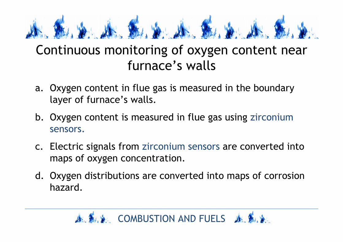
Continuous monitoring of oxygen content near
furnace’s walls
a. Oxygen content in flue gas is measured in the boundary
layer of furnace’s walls.
b. Oxygen content is measured in flue gas using zirconium
sensors.
c. Electric signals from zirconium sensors are converted into
maps of oxygen concentration.
d. Oxygen distributions are converted into maps of corrosion
hazard.

COMBUSTION AND FUELS
Zirconium sensors
=
2
2ln4 O
O
F
RTV ref
N
CmVF
RT o700at 9,204
=
where
COMBUSTION AND FUELS
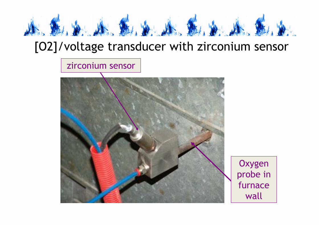
[O2]/voltage transducer with zirconium sensor
zirconium sensor
Oxygen
probe in
furnace
wall
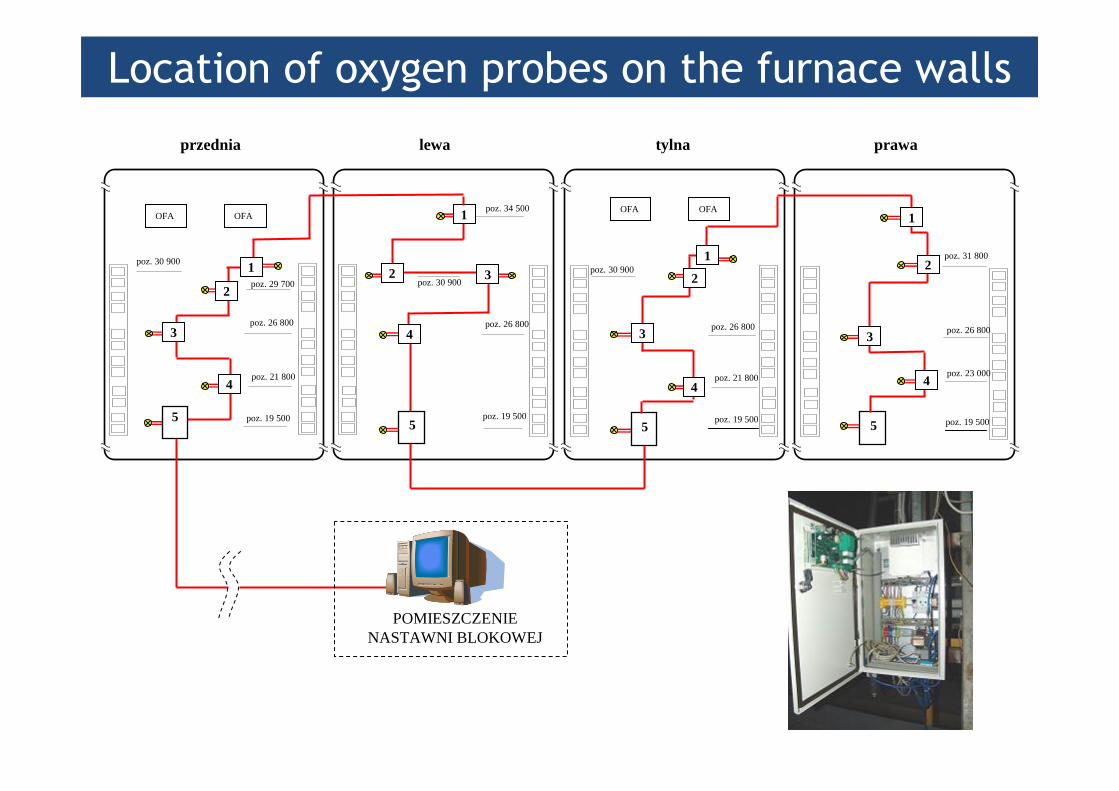
Location of oxygen probes on the furnace walls
poz. 30 900
poz. 19 500
poz. 26 800
poz. 34 500
lewa
poz. 30 900
poz. 19 500
poz. 26 800
poz. 21 800
OFA OFA
tylna
poz. 31 800
poz. 19 500
poz. 26 800
poz. 23 000
prawa
poz. 30 900
poz. 19 500
poz. 26 800
poz. 21 800
poz. 29 700
OFA OFA
przednia
2
3
4
1
2 3
4
55
POMIESZCZENIE NASTAWNI BLOKOWEJ
4
3
2
1
55
4
3
2
11

Maps of corrosion hazard


