MEASUREMENT OF BLAST-INDUCED PRESSURE IN BENCH BLASTING AND DECIPHERING EXPLOSIVE PERFORMANCE THROUGH ROCKMASS RESPONSE ANALYSIS – A METHODOLOGY Authored by A K Raina 1 & V M S R Murthy 2 Presented by V M S R Murthy 1. Central Institute of Mining and Fuel Research, RC, Nagpur and 2. Indian School of Mines, DhanbadIndia
Transcript
MEASUREMENT OF BLAST-INDUCED PRESSURE IN BENCH BLASTING AND DECIPHERING EXPLOSIVE PERFORMANCE
THROUGH ROCKMASS RESPONSE ANALYSIS – A METHODOLOGY
Authored by A K Raina 1 & V M S R Murthy 2
Presented by V M S R Murthy
1. Central Institute of Mining and Fuel Research, RC, Nagpur and 2. Indian School of Mines, DhanbadIndia
Introduction Fragmentation, throw & flyrock distance • Result of explosive action in the form of shock and
gaseous pressure in the blasthole. The rock mass • is deformed, fractured, and displaced from its
original location predominantly due to gaseous pressure.
2
Why measure Blast-Induced pressure ?
Blasthole pressure resulting from the detonation of the explosives • difficult to quantify :the measurement methods involved are: • cumbersome, • not very precise and • costly in nature.
The destructive nature of such tests inhibits further R&D on this front despite the fact that such pressures are of utmost importance in blast performance evaluation.
• The nature of blast hole pressure is also controlled by the extent of confinement and explosive properties apart from the nature of the rockmass itself in which the detonation takes place.
3
Why measure Blast-Induced pressure ?
0 Such considerations mandate a better and non-destructive method to determine the rock-explosive interaction 0 Pressures exerted by explosive gases on nearby
rockmass are thus important 0 as these can be measured directly instead of relying on
indirect estimation methods of explosive energy that have several associated errors
4
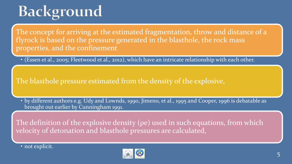
The concept for arriving at the estimated fragmentation, throw and distance of a flyrock is based on the pressure generated in the blasthole, the rock mass properties, and the confinement • (Essen et al., 2005; Fleetwood et al., 2012), which have an intricate relationship with each other.
The blasthole pressure estimated from the density of the explosive,
• by different authors e.g. Udy and Lownds, 1990, Jimeno, et al., 1995 and Cooper, 1996 is debatable as brought out earlier by Cunningham 1991.
The definition of the explosive density (ρe) used in such equations, from which velocity of detonation and blasthole pressures are calculated,
• not explicit. 5
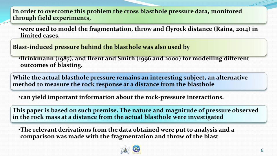
In order to overcome this problem the cross blasthole pressure data, monitored through field experiments,
•were used to model the fragmentation, throw and flyrock distance (Raina, 2014) in limited cases.
Blast-induced pressure behind the blasthole was also used by
•Brinkmann (1987), and Brent and Smith (1996 and 2000) for modelling different outcomes of blasting.
While the actual blasthole pressure remains an interesting subject, an alternative method to measure the rock response at a distance from the blasthole
•can yield important information about the rock-pressure interactions.
This paper is based on such premise. The nature and magnitude of pressure observed in the rock mass at a distance from the actual blasthole were investigated
•The relevant derivations from the data obtained were put to analysis and a comparison was made with the fragmentation and throw of the blast
6
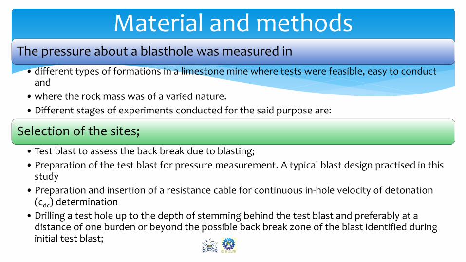
The pressure about a blasthole was measured in • different types of formations in a limestone mine where tests were feasible, easy to conduct
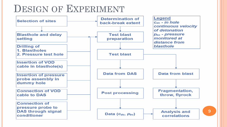
and •where the rock mass was of a varied nature. •Different stages of experiments conducted for the said purpose are:
Selection of the sites; • Test blast to assess the back break due to blasting; • Preparation of the test blast for pressure measurement. A typical blast design practised in this
study • Preparation and insertion of a resistance cable for continuous in-hole velocity of detonation
(cdc) determination •Drilling a test hole up to the depth of stemming behind the test blast and preferably at a
distance of one burden or beyond the possible back break zone of the blast identified during initial test blast;
Material and methods
7
MATERIALS AND METHODS CONT..
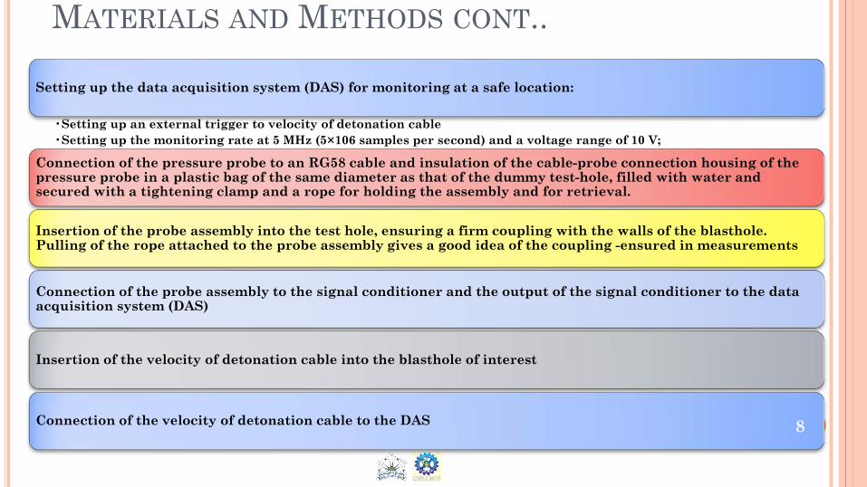
Setting up the data acquisition system (DAS) for monitoring at a safe location:
•Setting up an external trigger to velocity of detonation cable •Setting up the monitoring rate at 5 MHz (5×10⁶ samples per second) and a voltage range of 10 V;
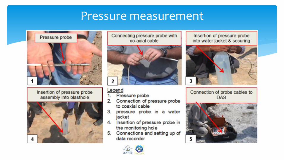
Connection of the pressure probe to an RG58 cable and insulation of the cable-probe connection housing of the pressure probe in a plastic bag of the same diameter as that of the dummy test-hole, filled with water and secured with a tightening clamp and a rope for holding the assembly and for retrieval.
Insertion of the probe assembly into the test hole, ensuring a firm coupling with the walls of the blasthole. Pulling of the rope attached to the probe assembly gives a good idea of the coupling -ensured in measurements
Connection of the probe assembly to the signal conditioner and the output of the signal conditioner to the data acquisition system (DAS)
Insertion of the velocity of detonation cable into the blasthole of interest
Connection of the velocity of detonation cable to the DAS 8
DESIGN OF EXPERIMENT
9
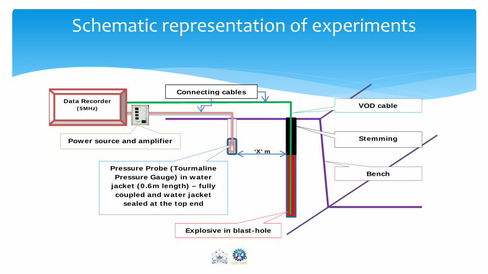
‘X’ m
Pressure Probe (Tourmaline Pressure Gauge) in water
jacket (0.6m length) – fully coupled and water jacket
sealed at the top end
Explosive in blast-hole
Stemming
Bench
VOD cable
Connecting cables
Power source and amplifier
Data Recorder (5MHz)
Schematic representation of experiments
10
In-hole continuous VOD measurement
11
Pressure measurement
12
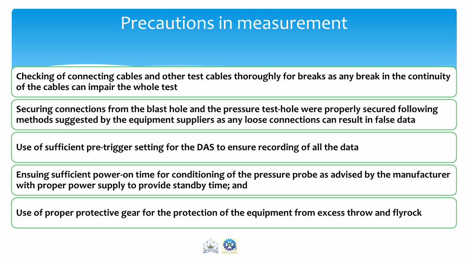
Checking of connecting cables and other test cables thoroughly for breaks as any break in the continuity of the cables can impair the whole test
Securing connections from the blast hole and the pressure test-hole were properly secured following methods suggested by the equipment suppliers as any loose connections can result in false data
Use of sufficient pre-trigger setting for the DAS to ensure recording of all the data
Ensuing sufficient power-on time for conditioning of the pressure probe as advised by the manufacturer with proper power supply to provide standby time; and
Use of proper protective gear for the protection of the equipment from excess throw and flyrock
Precautions in measurement
13
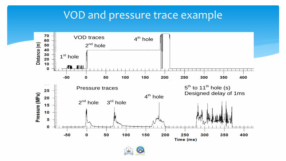
1st hole
Pressure traces
VOD traces
2nd hole 4th hole
2nd hole 3rd hole 4th hole
5th to 11th hole (s) Designed delay of 1ms
VOD and pressure trace example
14
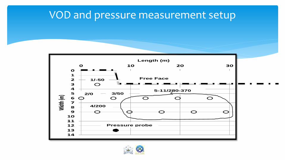
VOD and pressure measurement setup
1/-50
2/0 3/50
4/200
Free Face
Pressure probe
5-11/280-370
Length (m)
15
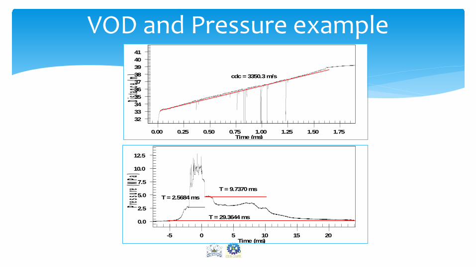
cdc = 3350.3 m/s
32333435363738394041
0.00 0.25 0.50 0.75 1.00 1.25 1.50 1.75Dista
nce (m)
Time (ms)
VOD and Pressure example
T = 29.3644 ms
T = 2.5684 ms T = 9.7370 ms
0.0
2.5
5.0
7.5
10.0
12.5
-5 0 5 10 15 20
Pressure
(MPa)
Time (ms)
16
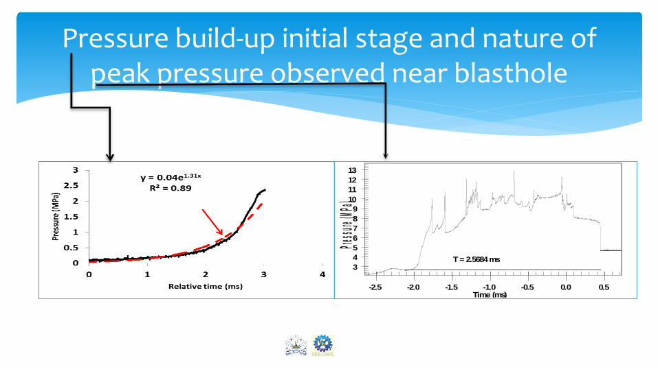
Pressure build-up initial stage and nature of peak pressure observed near blasthole
T = 2.5684 ms3456789
10111213
-2.5 -2.0 -1.5 -1.0 -0.5 0.0 0.5
Pressure
(MPa)
Time (ms)
17
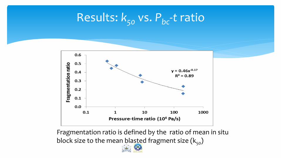
Results: k50 vs. Pbc-t ratio
Fragmentation ratio is defined by the ratio of mean in situ block size to the mean blasted fragment size (k50)
18
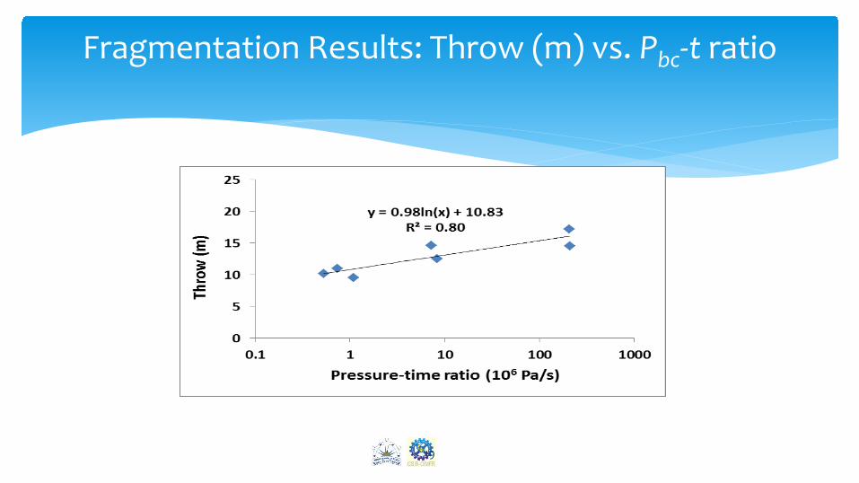
Fragmentation Results: Throw (m) vs. Pbc-t ratio
19
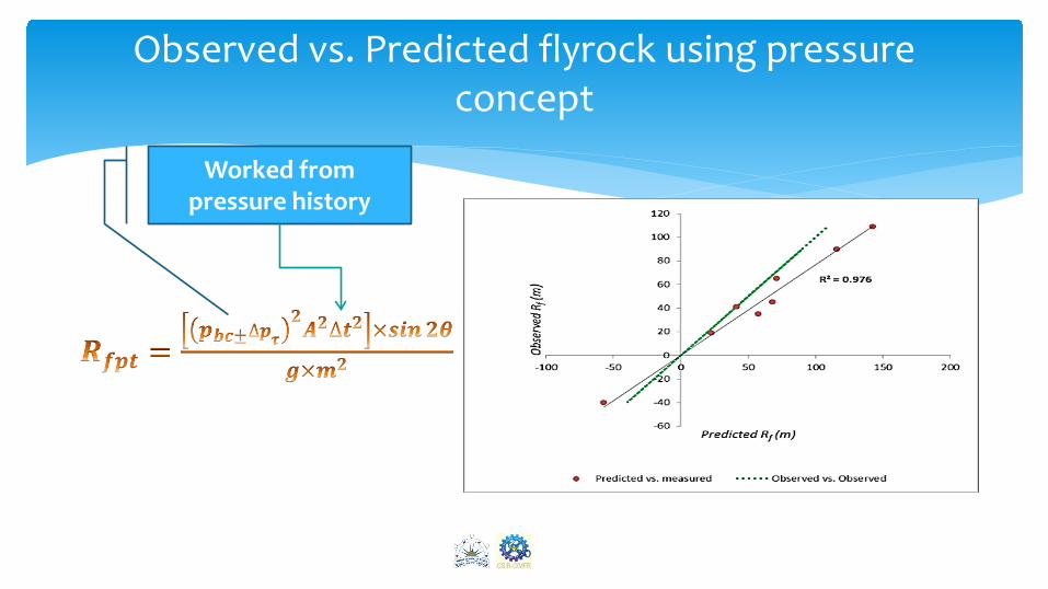
Observed vs. Predicted flyrock using pressure concept
20
Worked from pressure history
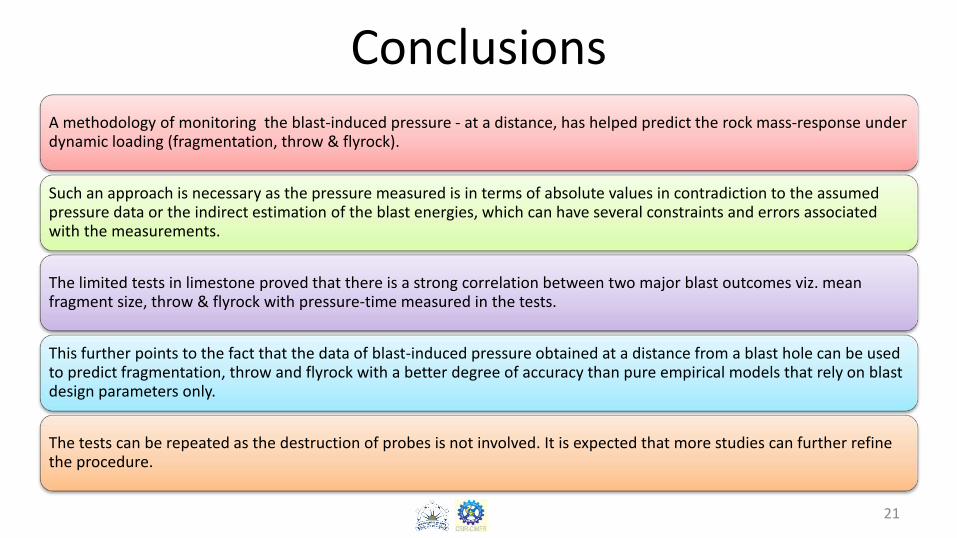
Conclusions A methodology of monitoring the blast-induced pressure - at a distance, has helped predict the rock mass-response under dynamic loading (fragmentation, throw & flyrock).
Such an approach is necessary as the pressure measured is in terms of absolute values in contradiction to the assumed pressure data or the indirect estimation of the blast energies, which can have several constraints and errors associated with the measurements.
The limited tests in limestone proved that there is a strong correlation between two major blast outcomes viz. mean fragment size, throw & flyrock with pressure-time measured in the tests.
This further points to the fact that the data of blast-induced pressure obtained at a distance from a blast hole can be used to predict fragmentation, throw and flyrock with a better degree of accuracy than pure empirical models that rely on blast design parameters only.
The tests can be repeated as the destruction of probes is not involved. It is expected that more studies can further refine the procedure.