Measurement of Cell Thickness in Infrared Spectrophotometry Giorgio Gambirasio It is shown that the usual expression for measuring the cell thickness da of an empty cell, namely, da = X 1 XN/2(X, - X,), where N is the number of fringes over the wavelength range Xi and X2, may only be applied under particular conditions of cell and wall thickness and spectrophotometer characteristics. This is done by first deriving the expression for the transmission coefficient of a cell taking into account all the four surfaces at which a discontinuity in the refractive index occurs (while in deriving the above formula only two such surfaces are considered). Then, by examining the spectrophotometer charac- teristics, we investigate what amount of the information contained in the variation of transmission coefficient with wavelength is actually recorded by the instrument. Formulas are developed for different situations, in which only cell thickness, both cell and wall thickness, and finally only wall thickness, may be measured by counting the number of fringes over a wavelength interval. The equation mentioned at the beginning is only valid for the first of these cases. 1. Introduction It is well known that the thickness da of a cell, as used in ir spectrophotometry, may be measured when empty by counting the number N of fringes between wavelengths Xi and X2, and by applying the equation da = XXN/2(X, -X 1 ). (1) Equation (1) may be easily derived by considering the reflections at the two inner surfaces of cell walls. Such an equation is stated or derived in most books and manuals without giving a warning about its limitations. In fact, the assumption upon which Eq. (1) is derived is not correct, since in the cell there are four surfaces at which a discontinuity in the refractive index occurs, not two. Still, Eq. (1) gives the correct answer in a number of cases. It is the purpose of this paper to derive formulas for the measurement of cell thickness by taking into account all four surfaces of discontinuity. It is also shown in this investigation that not only the optical characteristics of the cell must be considered in develop- ing a formula but also the characteristics of the spectro- photometer (S.P.) itself. When the latter are taken into account, it becomes apparent how to interpret correctly the results of fringe counting. In certain cases it is possible to measure both cell and wall thick- ness; in other cases, only wall thickness may be mea- sured. Finally, there are situations in which cell thickness alone may be measured, the appropriate formula for this case being Eq. (1). The author is with the Escola Politecnica da Universidade de S. Paulo, C.P. 8174, Sdo Paulo, Brazil. Received 29 July 1966. II. Derivation of Equations The cell is considered to have parallel walls of the same material and equal thickness d (Fig. 1). Let E and H (with appropriate sub- and superscripts as later explained), respectively, represent the intensity of the electric and magnetic fields of a monochromatic wave of angular frequency co. In Fig. 1, light comes from the left, perpendicularly to the walls; all E and H vectors are parallel to the walls. The equations describing the waves in each region of the cell are (a) incident wave (z < 0): (2) (3) Ei = Eo ei(kazwt) Hi = Yi; (b) reflected wave (z < 0): Er = Eei(-kaz-wt) Hr= -YaEr; (c) waves inside wall 1 (O < z < d): E2 (E2+eikwz + E2-e-ikwz)eiwt, H2 Y (E +eikW - E2eikz)eit; (d) waves inside cell (O < y < da) E3 = (E3+eikaY + E3-e-ikay)e-it, H3 = Y (E+eikay -E3-e-ikaY)e-iwt; (e) waves inside wall 2 (O < x < d,): E 4 = (E 4 +eikwx + E 4 -e -- ikwx)e -iwt, H 4 = Y (E4+eikx - E 4 -e-ikwx)e--iwt; (4) (5) (6) (7) (8) (9) (10) (11) March 1967 / Vol. 6, No. 3 / APPLIED OPTICS 477
Transcript
Measurement of Cell Thickness in Infrared Spectrophotometry
Giorgio Gambirasio
It is shown that the usual expression for measuring the cell thickness da of an empty cell, namely, da =X1XN/2(X, - X,), where N is the number of fringes over the wavelength range Xi and X2, may only beapplied under particular conditions of cell and wall thickness and spectrophotometer characteristics.This is done by first deriving the expression for the transmission coefficient of a cell taking into accountall the four surfaces at which a discontinuity in the refractive index occurs (while in deriving the aboveformula only two such surfaces are considered). Then, by examining the spectrophotometer charac-teristics, we investigate what amount of the information contained in the variation of transmissioncoefficient with wavelength is actually recorded by the instrument. Formulas are developed for differentsituations, in which only cell thickness, both cell and wall thickness, and finally only wall thickness, maybe measured by counting the number of fringes over a wavelength interval. The equation mentioned atthe beginning is only valid for the first of these cases.
1. IntroductionIt is well known that the thickness da of a cell, as
used in ir spectrophotometry, may be measured whenempty by counting the number N of fringes betweenwavelengths Xi and X2, and by applying the equation
da = XXN/2(X, - X1 ). (1)
Equation (1) may be easily derived by consideringthe reflections at the two inner surfaces of cell walls.Such an equation is stated or derived in most books andmanuals without giving a warning about its limitations.In fact, the assumption upon which Eq. (1) is derivedis not correct, since in the cell there are four surfaces atwhich a discontinuity in the refractive index occurs, nottwo. Still, Eq. (1) gives the correct answer in a numberof cases.
It is the purpose of this paper to derive formulas forthe measurement of cell thickness by taking intoaccount all four surfaces of discontinuity. It is alsoshown in this investigation that not only the opticalcharacteristics of the cell must be considered in develop-ing a formula but also the characteristics of the spectro-photometer (S.P.) itself. When the latter are takeninto account, it becomes apparent how to interpretcorrectly the results of fringe counting. In certaincases it is possible to measure both cell and wall thick-ness; in other cases, only wall thickness may be mea-sured. Finally, there are situations in which cellthickness alone may be measured, the appropriateformula for this case being Eq. (1).
The author is with the Escola Politecnica da Universidade deS. Paulo, C.P. 8174, Sdo Paulo, Brazil.
Received 29 July 1966.
II. Derivation of EquationsThe cell is considered to have parallel walls of the
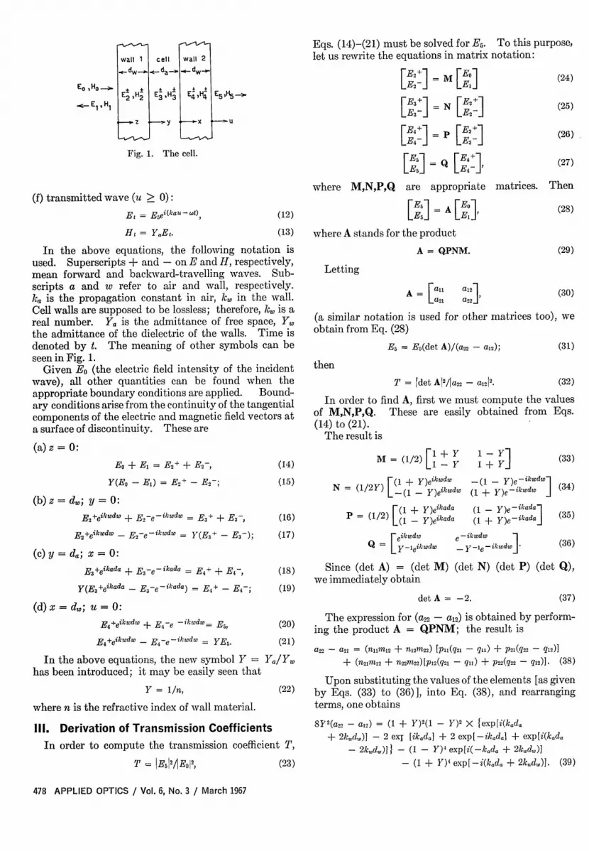
same material and equal thickness d (Fig. 1). Let Eand H (with appropriate sub- and superscripts as laterexplained), respectively, represent the intensity of theelectric and magnetic fields of a monochromatic waveof angular frequency co. In Fig. 1, light comes fromthe left, perpendicularly to the walls; all E and Hvectors are parallel to the walls.
The equations describing the waves in each region ofthe cell are
(a) incident wave (z < 0):
(2)
(3)
Ei = Eo ei(kazwt)
Hi = Yi;
(b) reflected wave (z < 0):
Er = Eei(-kaz-wt)
Hr= -YaEr;
(c) waves inside wall 1 (O < z < d):
E2 (E2+eikwz + E2-e-ikwz)eiwt,
H2 Y (E +eikW - E2eikz)eit;
(d) waves inside cell (O < y < da)
E3 = (E3+eikaY + E3-e-ikay)e-it,
H3 = Y (E+eikay -E3-e-ikaY)e-iwt;
(e) waves inside wall 2 (O < x < d,):
E4 = (E4 +eikwx + E4 -e --ikwx)e -iwt,
H4 = Y (E4+eikx - E4-e-ikwx)e--iwt;
(4)
(5)
(6)
(7)
(8)
(9)
(10)
(11)
March 1967 / Vol. 6, No. 3 / APPLIED OPTICS 477
Et H *2 2
Ri Z
cell wall 2
e-- da d
E3 ,H3 E4 ,H4 E5 ,H5-
y Y X MU
Fig. 1. The cell.
(f) transmitted wave (u > 0):Et = Esei(kau-W0)
Hi = YaEt.
(12)
Eqs. (14)-(21) must be solved for E5. To this purpose,let us rewrite the equations in matrix notation:
[,K] = M [.o][E2_ ] El]
[E, ] = N [E+]
[E4_ = p [E3]
[Es] = [E ,+] ,
where M,N,P,Q are appropriate
[E:1 = A [Ej
(24)
(25)
(26)
(27)
matrices. Then
(28)
(13) where A stands for the product
In the above equations, the following notation isused. Superscripts + and - on E and H, respectively,mean forward and backward-travelling waves. Sub-scripts a and w refer to air and wall, respectively.ka is the propagation constant in air, k,. in the wall.Cell walls are supposed to be lossless; therefore, k. is areal number. Ya is the admittance of free space, Y.the admittance of the dielectric of the walls. Time isdenoted by t. The meaning of other symbols can beseen in Fig. 1.
Given Eo (the electric field intensity of the incidentwave), all other quantities can be found when theappropriate boundary conditions are applied. Bound-ary conditions arise from the continuity of the tangentialcomponents of the electric and magnetic field vectors ata surface of discontinuity. These are
(a)z = 0:
A = QPNM. (29)
Letting
A- [als a,2 1a2l a22 '
(30)
(a similar notation is used for other matrices too), weobtain from Eq. (28)
E5 = Eo(det A)/(a 22 - a12); (31)
then
T = det A12/ja2 2 - al212. (32)
In order to find A, first we must compute the valuesof M,N,P,Q. These are easily obtained from Eqs.(14) to (21).
The result is
Eo + EM = E2+ + E2-,
Y(Eo - E) = E2 +-E2-;
(b) z = do; y = 0:
E2+eikwdw + E2-ek-ikwdw E3+ + Er-
E2+eikwdw - E2-eikwdw = Y(E 3 + - E3 -);
(c) y d; x = 0:
E3+eikada + E,3-e-ikada = E4 + + E4-
Y(E3+ikada - E3-e-ikada) = E4 + -E-;
(d) = do; u = 0:
E4 +eikwdw + E4 -e -ikwdw= E.,
E4 +eikwdw - E4 e -ikwdw = YE 5.
In the above equations, the new symbol Y =
has been introduced; it may be easily seen that
Y = 1/n,
where n is the refractive index of wall material.
(14)
(15)N = (1/2:
M = (1/2) [1 + i + Y] (33)
F( + )eikwdw -(1 - Y)e3ik4dl
L-(1 - Y)eikwdw (1 + Y)eikwdw J (34)
P = (1/2) [(1 - Y)eikada(16)
(17) eeiw cdiw
Q = Y-eikwdw0
(18)
(19)
(1 - Y)e-ikada-1
(1 + Y)e-ikada]
-ikdw]
-Y-le-ikwedw I
(35)
(36)
Since (det A) = (det M) (det N) (det P) (det Q),we immediately obtain
det A = -2. (37)
(20) The expression for (a22 - a12) is obtained by perform-(20) ing the product A = QPNM; the result is(21)
Equation (41) is the correct expression for thetransmission coefficient in a cell. It is considerablymore complicated than the one that leads to Eq. (1),which would read, in our notation, as
(47)The additional complication in Eq. (41) as compared
with Eq. (47) arises because the system of fringesactually depends upon both cell and wall thickness.Therefore, it is expected that not only da, but d aswell, may be obtained by inspection of the fringe system.That this is actually the case, under certain circum-stances depending on the S.P., is shown below. Inorder to proceed further in our investigation, a moremanageable function must be substituted for Eq. (41)so that the system of fringes may be described moreeasily. This is done with the introduction of thefringe function in Sec. IV.
IV. Derivation of the Fringe FunctionWhen the transmission coefficient of a cell is recorded
as a function of the wavelength of the radiation usinga S.P., the corresponding curve exhibits maxima andminima. Each complete cycle or wave of this curve iscalled a fringe. Every time a cosine function in Rchanges its value from +1 to -1, for instance, andthen back to +1, a new fringe occurs. (One assumesthat the wall material has no absorption band in therange of wavelength being considered.) Since thereare many such cosine functions in Eq. (42), it is dif-ficult at first sight to separate the contribution of eachone in the total variation of T. It happens, however,that the coefficients R1 to R4 have different orders ofmagnitude for the expected values of Y= 1/n; therefore,it is possible to sort out the leading terms in R.
For a refractive index n = 1.25, the numerical valuesare R= 110, R2 = 2.7, R3 = 0.0335, and R4 < 10-3.For n 1.5, we obtain R1 = 60, R2 = 4.84, R3 = 0.235,and R4 < 10-2. Therefore, it is reasonable to attributemost of the variation in T to the coefficient of R2.
One can define a function F, called the "fringe func-tion, " in such a way that F exhibits maxima and minimaat the same values of wavelength as T. Such a functionmay be understood as the coefficient of R2:
The introduction of F is justified since the quantityof interest is the number of fringes appearing in a givenwavelength interval rather than the actual value of thetransmission coefficient. The argument of F will befrequency, wavelength, or wavenumber, dependingupon one's choice.
We choose wavelength as a suitable argument andwrite a more explicit expression for F. Let X be thewavelength in free space, then ka = 27r/X. Also, let X,,be the wavelength inside the walls of refractive index n,then k, = 2r/X,, and nX,, = X. Then F(X) is
It would be tempting to say at this point that, as theS.P. scans its entire range of radiation wavelengths, theresulting absorption graph is a representation of F.This statement, however, would only be true for an idealS.P., which would reproduce all the variations of F, thewavelength being scanned from zero to infinity. Inpractice, a S.P. is a band limited device, and the absorp-tion graph recorded by the S.P. is only a filtered repre-sentation of F.
In order to further clarify the situation, we introducethe concept of fringes per wavelength (fpw), which isthe number of fringes appearing on a graph when theradiation wavelength is changed one unit. For exam-ple, for the first term in Eq. (49), we have fpw = 2(da +nd).
Since the S.P. scans a limited band of wavelengths,for example from X to X2, the lowest value L of fpw thatthe device is capable of recording is on the order of1/(X2-X 1). On the other hand, the servomechanism inthe recording system of the S.P. has a finite responsetime, the optical system has a finite resolution, etc.All these factors set an upper limit U to the highest fpwthat can actually be discernible on the graph. There-fore, of all the values of fpw that F(X) would exhibitwhen X is (ideally) varied from zero to infinity, the S.P.only records those values inside the bandpass (L, U).This limitation of the instrument imposes a correspond-ing limitation on the values of d and d that can bemeasured by fringe counting on the graph.
VI. Measurement of ThicknessesLet F(X) be the representation of F(X) as recorded
by the S.P.
March 1967 / Vol. 6, No. 3 / APPLIED OPTICS 479
Suppose now that d is so great that 2 nd, > U,U > 2 da > L. Then only the last term in F(X) iscorded by the S.P.; that is,
F,(X) = -2 cos(47rda/X).
Now cell thickness da can be measured by fricounting by a formula which is exactly like Eq.This is the only case in which this equation givescorrect result. Such a situation arises with most sltrophotometers when, for example, the cell has Nwalls of 5 mm in thickness and da is of the order of atenths of a millimeter-a common case in ir speciphotometry.
Now let d be reduced to such an extent that e2(da + 2 ndz) < U. Then all the values of fpw toccur in the band scanned will be recorded by the Sthat is, F(X) and F1 (X) coincide. In this case, it is beto rewrite F(X) by simple trigonometric transformati
The first term in Eq. (51) represents a modulkwave: cos[47r(da + nd)/XI is the carrier, cos(47rnd,is the envelope or modulating wave. The second t
is again the modulating wave; added to the first teit modifies the shape of the envelope, not its fpw. case occurs when, for example, cell walls are madipolymer film a few hundredths of a millimeter thspaced a few tenths of a millimeter. By countingnumber of fringes Ne of only the envelope, overwavelength range of X\2- X1 , we obtain
nd. = X1 X2N,/2(X2 - X).
Likewise, by counting the number of fringes Nthe carrier over the wavelength range 4 - ,
instance, we obtain
da + nd. = X3X4N/2(X4 - X3)-
Only the above equations are applicable here, not Eq.
(1).Obviously, the cell thickness da is obtained by sub-
traction of the above measurements. The successfulapplication of Eqs. (52) and (53) requires that the re-fractive index n be known and also that it be fairlyconstant over the range of variation of X over whichfringes are counted. It is also necessary for da and d4wto be at least one order of magnitude apart. If theyhave values too close to each other, it becomes difficultto clearly identify the carrier and the envelope on thegraph.
As a final example, let us consider a cell in which thewalls are thin, but da is so great that 2 da > U. How-ever, U > nd,, > L. In this case, F1 (X) is
F,(X) = -2 cos(47rnd./X); (54)
that is, only wall thickness can be measured from thegraph. Then
nd. = XX2 /2(X 2 - 1 ), (55)
Lted where N is the number of fringes measured over the,/X) wavelength range X2 - XI-;erm
rms V1. ConclusionsP'hisLe of It is apparent from the foregoing considerations thatick, Eq. (1) is only applicable under particular conditions ofthe cell size and S.P. characteristics. The same is true forthe the other formulas given here. One must consider both
the characteristics of the instrument and the order of(2 magnitude of da and d, (which can be estimated before-
(52) hand) before deciding which one of the given formulasof is appropriate.
for Thanks are due to F. Gambirasio and T. R. M. Mollanof Instituto de Pesquisas Tecnol6gicas, Sdo Paulo, for
(53) suggesting this investigation.
Summer Course on Fundamentals of OpticsInstitute of Optics, University of Rochester10-21 July 1967
The program is an intensive two-week course designed for physicists and engineers in industryand government, and for college teachers of physics and electrical engineering. About 60hours of lectures, drawn primarily from the Institute's regular academic program, have beenselected to provide a useful foundation in certain optical areas of practical interest. The lec-turers are drawn from the Institute of Optics' faculty: P. W. Baumeister, M. P. Givens, M.Hercher, R. E. Hopkins, W. L. Hyde, R. Jacobsson, K. Sayanagi, D. C. Sinclair, and H. A. Unvala;and Lawrence Mertz, of Block Engineering, Inc. Lectures will treat coherence (1 h), polarizedlight (4 h), Gaussian optics, instruments, and system layout (8 h), lens design and optimizat on(5h), image structure and transfer (5 h), lasers (6 h), radiometry (10 h), interferometry andFourier methods in spectroscopy (4 h), modulators and deflectors (2 h), multilayer filters (5 h),and holograms (4 h). Academic level is that of an advanced undergraduate course, but with areduced emphasis on formal proofs and an increased emphasis on applications. Participantsare assumed to have the equivalent of a bachelor's degree in physics or engineering.Tuition for the course, including an extensive set of notes and two books, will be $400 ($425 forapplications received after 1 June). Living and dining facilities will be available on campus.Tuition remission, stipends and travel allowances will be provided for a maximum of 20 collegeteachers of physics and electrical engineering; stipends and travel funds come from a NationalScience Foundation grant in support of the program. The deadline for applications for financialaid is 1 March 1967. The course carries no academic credit. Requests for further informa-tion and for enrolment applications should be directed to Fundamentals of Optics, Institute ofOptics, University of Rochester, Rochester, New York 14267.