Defence R&D Canada – Atlantic DEFENCE DÉFENSE & Measurement of Diffusible Hydrogen in Seamed Flux Cored Wires for Welding of High Strength Steels DRDC Atlantic Report on TTCP MAT-TP1 Operating Assignment 45 D. E. Veinot P. E. Fraser L. W. MacGregor Technical Memorandum DRDC Atlantic TM 2007-032 November 2007 Copy No. _____ Defence Research and Development Canada Recherche et développement pour la défense Canada
Transcript
Defence R&D Canada – Atlantic
DEFENCE DÉFENSE&
Measurement of Diffusible Hydrogen in
Seamed Flux Cored Wires for Welding of
High Strength Steels
DRDC Atlantic Report on TTCP MAT-TP1 OperatingAssignment 45
D. E. Veinot
P. E. Fraser
L. W. MacGregor
Technical Memorandum
DRDC Atlantic TM 2007-032
November 2007
Copy No. _____
Defence Research andDevelopment Canada
Recherche et développementpour la défense Canada
This page intentionally left blank.
Measurement of Diffusible Hydrogen in Seamed Flux Cored Wires for Welding of High Strength Steels DRDC Atlantic Report on TTCP MAT-TP1 Operating Assignment 45
Original signed by P. E. Fraser and L. W. MacGregor
Original signed by C. V. Hyatt
Original signed by James. L. Kennedy
DRDC Atlantic TM 2007-032 i
Abstract
This report describes the measurement of diffusible hydrogen in weld test specimens made on high strength steel coupons using seamed flux cored wires. The report represents Canada’s contribution to the TTCP MAT TP1 operating assignment OA-45. The objectives of this activity were to increase the confidence of present analytical practices; to identify the best approaches to accurately measure the hydrogen content in welds made using flux cored wires; and to understand the parameters which impact on precision and accuracy of the diffusible hydrogen measurement.
Résumé
Dans le présent rapport, on décrit les mesures d’hydrogène diffusible dans des éprouvettes en acier de haute résistance soudées au moyen de fils à bords rabattus avec âme en flux. Ce rapport représente la contribution du Canada à l’affectation d’exécution OA-45 de TTCP MAT TP1. L’objectif de cette activité était d’avoir une confiance accrue dans les méthodes actuelles d’analyse, d’identifier les meilleures approches pour une mesure précise de la teneur en hydrogène de soudures réalisées avec des fils à âme en flux, et de comprendre les paramètres ayant une influence sur la précision et l’exactitude des mesures de la diffusion d’hydrogène.
ii DRDC Atlantic TM 2007-032
This page intentionally left blank.
DRDC Atlantic TM 2007-032 iii
Executive summary
The role of hydrogen in delayed cracking of weldments in carbon steels and low alloy steels has long been recognized. It is well known that cracking is promoted by higher strength microstructures such as martensite, higher stresses such as residual stresses imposed by welding in restrained sections and higher levels of diffusible hydrogen in the welded piece.
This report describes the measurement of diffusible hydrogen in weld test specimens made on high strength steel coupons using seamed flux cored wires. The report represents Canada’s contribution to the TTCP MAT TP1 operating assignment 45. The objective of this activity was to develop a simplified list of diffusible hydrogen tests, welding materials, welding processes, and parameters that have been round robin tested by the participating nations to increase the confidence of present analytical practices and identify the best approaches to accurately measure quality of flux-cored filler wires.
The results obtained here suggest that acceptable diffusible hydrogen levels can be obtained on welding high strength steels using seamed flux cored electrodes and that use of pure carbon dioxide as shield gas yields lower measured diffusible hydrogen levels than those obtained when using the Canadian liquid Air, Inc. proprietary product, Blue Shield 8 as shielding gas. The results also suggest that the wire conditioning procedure employed had little effect on diffusible hydrogen content and, if anything, conditioning appeared to slightly lower the measured levels
This work will form the Canadian contribution to the TTCP-MAT-TP1 summary report on Operating Assignment 45 (OA45), which will also include results from a United States navy laboratory and results from the electrode suppliers. That summary report is expected to be available in the summer of 2007.
Veinot, D. E., Fraser, P. E and MacGregor, L. W., Measurement of Diffusible Hydrogen in Seamed Flux Cored Wires for Welding of High Strength Steels: DRDC Atlantic Report on TTCP MAT-TP1 Operating Assignment 45, DRDC Atlantic TM 2007-032. Defence Research and Development Canada – Atlantic. November 2007.
iv DRDC Atlantic TM 2007-032
Sommaire
Il y a longtemps que le rôle de l’hydrogène dans la fissuration retardée d’assemblages soudés en acier au carbone et en acier faiblement allié a été reconnu. Il est bien connu que la fissuration est favorisée par des microstructures à haute résistance, comme la martensite, des contraintes plus élevées, comme les contraintes résiduelles imposées par le soudage dans des sections restreintes, et des teneurs en hydrogène diffusible plus élevées dans les pièces soudées.
Dans le présent rapport, on décrit les mesures d’hydrogène diffusible dans des éprouvettes en acier de haute résistance soudées au moyen de fils à bords rabattus avec âme en flux. Ce rapport représente la contribution du Canada à l’affectation d’exécution OA-45 de TTCP MAT TP1. L’objectif de cette activité était d’établir une liste simplifiée de tests sur l’hydrogène diffusible, de matériaux pour le soudage, de procédés de soudage et de paramètres testés et comparés par les nations participantes afin d’accroître la confiance dans les méthodes actuelles d’analyse et d’identifier les meilleures approches pour une mesure précise de la qualité des fils à âme en flux.
Les résultats obtenus amènent à penser que des niveaux acceptables d’hydrogène diffusible peuvent être atteints lors du soudage d’acier de haute résistance au moyen d’électrodes à bords rabattus et âme en flux. Ce soudage réalisé en atmosphère de dioxyde de carbone pur conduit à des teneurs mesurées d’hydrogène diffusible inférieures à celles mesurées pour le soudage en atmosphère de Blue Shield 8, le produit propriété exclusive d’Air Liquide Canada Inc. Ces résultats amènent aussi à penser que la procédure de conditionnement du fil utilisée a peu d’effet sur la teneur en hydrogène diffusible et que, au cas où elle aurait un effet, cet effet serait l’obtention de teneurs légèrement plus faibles.
Le présent travail constituera la contribution du Canada au rapport sommaire de l’affectation d’exécution 45 (OA-45) de TTCP-MAT-TP1, rapport qui comprendra également des résultats du laboratoire de la Navy des Etats-Unis et des fournisseurs des électrodes. Ce rapport sommaire devrait être disponible au cours de l’été 2007.
Veinot, D. E., Fraser, P. E and MacGregor, L. W., Measurement of Diffusible Hydrogen in Seamed Flux Cored Wires for Welding of High Strength Steels: DRDC Atlantic Report on TTCP MAT-TP1 Operating Assignment 45, DRDC Atlantic TM 2007-032. Defence Research and Development Canada – Atlantic. November 2007.
DRDC Atlantic TM 2007-032 v
Table of contents
Abstract........................................................................................................................................ i
Executive summary ................................................................................................................... iii
Sommaire................................................................................................................................... iv
Table of contents ........................................................................................................................ v
List of figures ............................................................................................................................ vi
Acknowledgements .................................................................................................................. vii
Distribution list ......................................................................................................................... 15
vi DRDC Atlantic TM 2007-032
List of figures
Figure 1. Clamping fixture used to hold weld test assemblies ................................................. 11
Figure 2. Oerlikon-Yanaco HDM analyzer Model G-1006........................................................ 11
Figure 3. Oerlikon-Yanaco sampler Model GS-1006............................................................... 12
Figure 4. Diffusible hydrogen in welds made using seamed flux cored wire and CO2 shield gas ..................................................................................................................................... 12
Figure 5. Diffusible hydrogen in welds made using seamed flux cored wire and BS8 shield gas ..................................................................................................................................... 13
List of tables
Table 1. Data for diffusible hydrogen study............................................................................. 10
DRDC Atlantic TM 2007-032 vii
Acknowledgements
The authors gratefully acknowledge the willing support of Ms. G. Pelletier, Mr. Peter Huntley and Mr. Rick Mosher of FMFCS, who assisted with the preparation of the weld test assemblies used in this study.
viii DRDC Atlantic TM 2007-032
This page intentionally left blank.
DRDC Atlantic TM 2007-032 1
1. Introduction
The role of hydrogen in delayed cracking of welds in carbon steels and low alloy steels has long been recognized. It is known that cracking is promoted by higher strength microstructures such as martensite, higher stresses such as residual stresses imposed by welding in restrained sections and higher levels of diffusible hydrogen in the welded piece.
During arc welding, monatomic hydrogen (H) is produced in the arc by the
decomposition of hydrogenous compounds, which enter the arc. The three most probable sources of these hydrogenous compounds are (1) the welding consumables such as the electrode and its flux or shielding gas which may contain water, lubricants or elemental hydrogen, (2) the base metal which may contain water, lubricants, elemental hydrogen, paints or other coatings, and (3) aspirated air from the surrounding area with its own water which may enter the welding arc to a certain extent. Judicious control of moisture content in the welding consumables and cleaning and preheating of the base metal are the most often used means of controlling the source of these hydrogenous compounds which, if not contained within predetermined levels, can lead to unacceptable levels of diffusible hydrogen in the weld.
Monatomic hydrogen is known to be extensively soluble in the weld pool and
is retained in solution when the weld pool solidifies. In solid martensitic, bainitic and ferritic materials, hydrogen diffuses rapidly even at temperatures as low as room temperature, and the rate of diffusion increases with increasing temperature. There is general agreement that the conditions that lead to hydrogen induced cracking during welding are: (1) a critical diffusible hydrogen concentration, (2) residual and applied stress above a certain level and (3) a susceptible microstructure. All three conditions are interrelated and thus a variation in any one can affect the others impact on hydrogen induced cracking. Cracking is often delayed for some hours after welding because of the time needed for hydrogen to diffuse to the crack site and hence the names “delayed” and “cold” cracking have often been used to describe the phenomenon.
It is difficult or impossible to totally control the resulting stresses and
temperatures in high strength steel welds, so measures to reduce hydrogen induced cracking must rely on control of hydrogen level or microstructure or both. Measurements of weld hydrogen levels provide a way of assessing the degree to which a given electrode, flux or shielding gas may introduce hydrogen into the weld pool. This may help in the determination of the possible sources of hydrogen, providing means to control their levels, such as cleaning surfaces to remove hydrogenous material and baking electrodes to remove excess moisture. Such
2 DRDC Atlantic TM 2007-032
measurements may also provide some insight for calculating heat treatment to remove hydrogen after welding.
Hydrogen, unlike other elements in weld metal, diffuses rapidly at normal
room temperatures, and some of it may escape before an analysis can be made. This coupled with the fact that the concentrations to be measured are usually at the part per million level, means that special sampling and analysis procedures are needed. For example, when hydrogen concentrations in the welded piece are found to be at a published acceptable upper level value of 5 mL per 100 g of weld metal (1) there is about 4.5 parts per million (wt/wt) of hydrogen in the metal. A further complication caused by the rapid rate of diffusion of hydrogen from the weld metal relates to the unavailability of standard materials containing known quantities of hydrogen for comparison of analytical results to obtain a measure of accuracy. Unlike other interstitial elements, hydrogen is transient in the metal and escapes the metal quite rapidly thus making the preparation of standards impractical if not impossible.
However, despite the difficulty in obtaining accurate hydrogen measurements
in metal, use of an analytical method with suitable sensitivity and repeatability for hydrogen content and a controlled standardized weld testing process can yield useful and reproducible information on welding processes and consumables that can provide information useful in reducing hydrogen levels in welds.
This report describes use of a gas chromatographic analytical procedure to
determine diffusible hydrogen in standard weld test specimens made on HY80 steel coupons using seamed flux cored wires and an American Welding Society general procedure(2) which formed Canada’s contribution to a TTCP-MAT-TP1 Operating assignment.
DRDC Atlantic TM 2007-032 3
2. Experimental Procedure
2.1 Preparation of HY80 coupons Weld test assemblies (130mm x 25mm x 12.5mm) were cut from HY80 steel
plate. Each weld test assembly was further sectioned along the large dimension into three separate segments providing for a starting weld tab (40mm x 25mm x 12.5mm), a run-off weld tab (40mm x 25mm x 12.5 mm) and a test specimen weld tab (50mm x 25mm x 12.5mm). Each segment of the 3 segment weld test assembly was labeled A, B or C preceded by an identifying number for the assembly on an uninvolved edge using a metal indenter, such as 1A, 1B and 1C for weld test assembly one, and so on, sequentially for the rest of the three segment weld test assemblies used in the study. The B component of each assembly was the component that comprised the actual test specimen on which diffusible hydrogen content was determined while the A segment of each assembly was provided for the starting weld tab and the C segment of each assembly was provided for the run-off weld tab. All the metal segments were subjected to heat treatment at 650o C in an inert gas atmosphere for one hour to remove any hydrogen present in the material. The surfaces of all the specimens were then cleaned of scale and other oxide residue by blasting with silicon beads and then washed in acetone and air-dried to remove any oily residue.
2.2 Weld Bead Deposition All segments of all weld test assemblies were weighed accurately to the
nearest 0.01 g and the weights for each recorded. The test assemblies were then transported to the weld site in oil and moisture free containers and positioned in the specially designed and constructed copper clamping fixture which was held in a mechanics vise as shown in Figures 1 using oil free metallic tongs to handle the specimens. A weld bead was then deposited on the top surface of the specimens using a manual metal arc procedure starting on segment A and following a straight path across segments B and C using seamed flux cored wires. The weld bead was started at least 25 mm from the start of segment B on segment A and continued non-stop to at least 25 mm beyond the run-off side of segment B on segment C. The total time to deposit the weld bead was measured to the nearest second for each weld assembly and recorded. From this time and the length of the weld bead it was possible to calculate the weld travel speed.
Immediately after depositing the weld bead on each weld test assembly and
within no longer than 5 seconds after extinguishing the arc, the weld test assembly was transferred using tongs to an ice/water bath and agitated while in the bath for 60 seconds. The cooled weld test assembly was then transferred to a liquid nitrogen bath and held submerged in the bath until vigorous boiling of the liquid nitrogen had
4 DRDC Atlantic TM 2007-032
subsided (approximately 3-5 minutes). The weld test assembly was then quickly removed from the bath using tongs and the total weld bead length was measured to the nearest mm. The weld test assembly was then positioned vertically on a slightly inclined angle against a solid metal support so that it could be hit soundly with a metal hammer to break the weld bead at the joints between segments A and B and segments B and C. Segment B was quickly returned to the liquid nitrogen bath such that the length of time that the assembly was out of the bath was insufficient for the specimen to warm above 0oC, that is, this operation was accomplished in less than 30 seconds. The separated B segments of each weld assembly were kept in the liquid nitrogen bath and returned to the laboratory for further analysis. Weld test assemblies in sets of four were prepared to measure diffusible hydrogen content.
2.3 Quantitative Diffusible Hydrogen Analysis
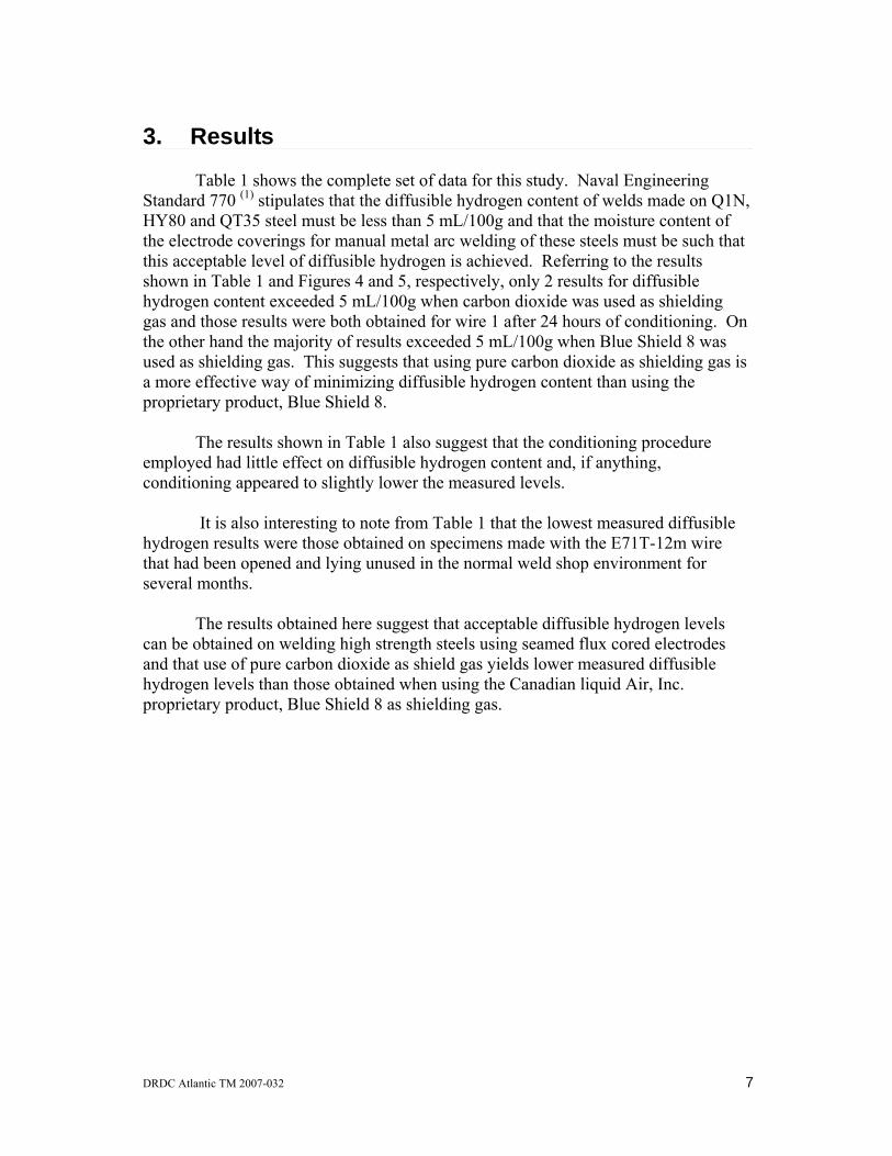
Diffusible hydrogen content in the weld test assemblies was determined using the Oerlikon-Yanaco HDM Analyzer Model G-1006 and the Oerlikon-Yanaco Sampler Model GS-1006. This equipment is shown in Figures 2 and 3, respectively. The analysis procedure involved evolution of diffusible hydrogen from each prepared weld test segment B by heating for a prescribed period of time in an oven while the segment B is contained within the argon filled atmosphere of the model GS-1006 sealed sampler. The gas containing any hydrogen released from the sample, which accumulates inside the sealed argon filled sampler was then flushed onto the packed column of the G-1006 HDM gas chromatographic analyzer. The model G-1006 HDM analyzer separates the various gases contained within the sampler in time as they pass through the packed column being carried by a constant flow of argon carrier gas and sequentially these gases enter the detector component of the analyzer. The unit employs a thermal conductivity type detector and its response is proportional to the thermal conductivity of the gases, which enter it after exiting the column. Thus when the argon carrier gas contains an amount of hydrogen in the sample channel, the detector senses a difference in thermal conductivity between the sample channel and the reference channel, which always contains pure argon. The detector response is directly proportional to the quantity of hydrogen in the sample channel.
All weld test assemblies prepared as in section 2.2 above were immediately
returned to the laboratory ensuring that they were continuously held in liquid nitrogen and then each was removed, one at a time, from the liquid nitrogen bath using metal tongs and any deposited slag was physically removed from the specimen without ever allowing the specimen to warm above 0o C. This sometimes necessitated re-cooling the specimen in liquid nitrogen several times before successful removal of all slag was complete. The segment B specimen was then quickly transferred to a numbered airtight chamber of the sampler and argon gas was allowed to flow through the chamber at a rate of 300 mL per minute for 30 seconds, after which the valve on that
DRDC Atlantic TM 2007-032 5
chamber was closed. This operation was completed sequentially for each of the segment B specimens, with only one specimen being held in each chamber of the sampler. The sampler was then transferred to a warming oven held at 50o C and kept there for 72 hours during which time any diffusible hydrogen in the metal was released and trapped in the airtight argon filled chamber.
The sampler was then removed from the oven, allowed to reach room
temperature and then connected to the HDM analyzer ports. The analyzer output was then zeroed using pure argon gas and calibrated for hydrogen content using pure hydrogen as described in the operation manual for the analyzer. Then the gases in each chamber were analyzed, one after the other, for hydrogen content, which was expressed in mL, the unit of measure output from the analyzer. Specimens were then removed from the analyzer chambers and weighed to the nearest 0.01 g and the weight of deposited weld metal on each segment was calculated and recorded. This weight and the measured volume of hydrogen released from each specimen was used to calculate the level of diffusible hydrogen in mL H2 per 100 grams of deposited weld metal, the units required by the standard (1).
2.4 Calculation of Heat Input
The heat inputs in kilojoules per millimeter for the arc welding procedure used here were calculated using the measured voltage, (volts), and the measured current, (amps) and the calculated weld travel speed (WTS) in mm/sec using the formula provided by Naval Engineering Standard (1), which is as follows:
(mm/sec) Speed Travel x Weld1000Amperage Volts Arc
m)(kjoules/mInput Heat ×
=
The recommended heat inputs for welding Q1N is between 1.18 to 2.17
kjoules/mm unless otherwise specified (1). Therefore, for this study, welders attempted to stay within this heat input range for all weld test assemblies produced. Further, heat input variation was normally controlled by adjusting weld travel speed because welders normally prefer to alter weld travel speed to affect heat input and do not normally alter voltage and/or amperage in actual operation, since it is normal to used predetermined voltage and amperage levels to obtain the preferred arc characteristics for a given electrode.
2.5 Wires tested All flux cored wires used in this study were obtained and distributed to participating countries by the United States representatives to TTCP MAT TP1. These wires were as follows:
6 DRDC Atlantic TM 2007-032
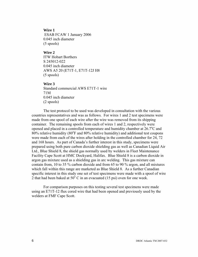
Wire 1 ESAB FCAW 1 January 2006 0.045 inch diameter (5 spools) Wire 2 ITW Hobart Borthers S 245012-022 0.045 inch diameter AWS A5 20 (E71T-1, E71T-12J H8 (5 spools) Wire 3 Standard commercial AWS E71T-1 wire 71M 0.045 inch diameter (2 spools) The test protocol to be used was developed in consultation with the various countries representatives and was as follows. For wires 1 and 2 test specimens were made from one spool of each wire after the wire was removed from its shipping container. The remaining spools from each of wires 1 and 2, respectively were opened and placed in a controlled temperature and humidity chamber at 26.7oC and 80% relative humidity (80oF and 80% relative humidity) and additional test coupons were made from each of the wires after holding in the controlled chamber for 24, 72 and 168 hours. As part of Canada’s further interest in this study, specimens were prepared using both pure carbon dioxide shielding gas as well as Canadian Liquid Air Ltd., Blue Shield 8, the shield gas normally used by welders in Fleet Maintenance Facility Cape Scott at HMC Dockyard, Halifax. Blue Shield 8 is a carbon dioxide in argon gas mixture used as a shielding gas in arc welding. This gas mixture can contain from, 10 to 35 % carbon dioxide and from 65 to 90 % argon, and all mixtures which fall within this range are marketed as Blue Shield 8. As a further Canadian specific interest in this study one set of test specimens were made with a spool of wire 2 that had been baked at 50o C in an evacuated (15 psi) oven for one week. For comparison purposes on this testing several test specimens were made using an E71T-12 flux cored wire that had been opened and previously used by the welders at FMF Cape Scott.
DRDC Atlantic TM 2007-032 7
3. Results
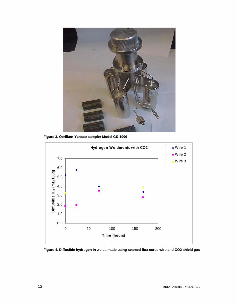
Table 1 shows the complete set of data for this study. Naval Engineering Standard 770 (1) stipulates that the diffusible hydrogen content of welds made on Q1N, HY80 and QT35 steel must be less than 5 mL/100g and that the moisture content of the electrode coverings for manual metal arc welding of these steels must be such that this acceptable level of diffusible hydrogen is achieved. Referring to the results shown in Table 1 and Figures 4 and 5, respectively, only 2 results for diffusible hydrogen content exceeded 5 mL/100g when carbon dioxide was used as shielding gas and those results were both obtained for wire 1 after 24 hours of conditioning. On the other hand the majority of results exceeded 5 mL/100g when Blue Shield 8 was used as shielding gas. This suggests that using pure carbon dioxide as shielding gas is a more effective way of minimizing diffusible hydrogen content than using the proprietary product, Blue Shield 8.
The results shown in Table 1 also suggest that the conditioning procedure
employed had little effect on diffusible hydrogen content and, if anything, conditioning appeared to slightly lower the measured levels.
It is also interesting to note from Table 1 that the lowest measured diffusible
hydrogen results were those obtained on specimens made with the E71T-12m wire that had been opened and lying unused in the normal weld shop environment for several months.
The results obtained here suggest that acceptable diffusible hydrogen levels
can be obtained on welding high strength steels using seamed flux cored electrodes and that use of pure carbon dioxide as shield gas yields lower measured diffusible hydrogen levels than those obtained when using the Canadian liquid Air, Inc. proprietary product, Blue Shield 8 as shielding gas.
8 DRDC Atlantic TM 2007-032
4. Conclusions
The results obtained here suggest that acceptable diffusible hydrogen levels can be obtained on welding high strength steels using seamed flux cored electrodes. Further, the use of pure carbon dioxide as shield gas yields lower measured diffusible hydrogen levels than those obtained when using the Canadian Liquid Air, Inc. product, Blue Shield 8. Conditioning wire at predetermined constant temperature and humidity appeared to have little effect on measured diffusible hydrogen levels while baking the wire in an evacuated oven before use may be beneficial.
DRDC Atlantic TM 2007-032 9
5. Future Work
A TTCP report summarizing the results of these and similar measurements by a United States Navy Laboratory and some of the electrode suppliers is expected to be available in the summer of 2007.
10 DRDC Atlantic TM 2007-032
Table:. Data for diffusible hydrogen study
time (hr) 80/80 Wire Shield Gas
Weld Deposit
(g)
Diff H2 (mL/100g)
Relative Humidity
(%)
Voltage (V)
Current (A)
WTS (mm/sec)
Heat Input (kjoule/mm)
0 1 CO2 8.3 5.54 52 26 215 5.21 1.07 0 1 CO2 8.4 4.88 52 26 215 5.21 1.07
24 1 CO2 8.4 5.24 51 26 210 4.76 1.15 24 1 CO2 9.2 6.30 51 26 215 4.76 1.17 72 1 CO2 7.7 4.16 44 26 215 4.57 1.22 72 1 CO2 8.7 3.79 44 26 215 4.76 1.17
168 1 CO2 8.1 3.58 44 26 210 4.95 1.10 168 1 CO2 8.1 3.83 44 26 210 4.95 1.10 168 1 CO2 9.4 2.81 44 26 210 4.40 1.24
0 2 CO2 8.8 1.66 58 26 210 4.06 1.34 24 2 CO2 8.4 1.74 58 26 210 4.23 1.29 24 2 CO2 9.9 2.12 58 26 190 3.81 1.30 72 2 CO2 8.7 3.84 29 26 195 3.43 1.48 72 2 CO2 10.7 3.22 29 26 195 4.06 1.25
168 2 CO2 9.1 2.46 50 26 200 4.06 1.28 168 2 CO2 9.6 2.75 50 26 200 4.02 1.29 168 2 CO2 10.4 2.78 50 26 200 3.81 1.36 168 2 CO2 10.3 3.20 50 26 200 3.81 1.36
open in shop months E71T-12M CO2 7.3 2.25 44 26 230 6.01 0.99 open in shop months E71T-12M CO2 7.9 1.73 44 26 225 5.46 1.07
DRDC Atlantic TM 2007-032 11
Figure 1. Clamping fixture used to hold weld test assemblies
Figure 2. Oerlikon-Yanaco HDM analyzer Model G-1006
12 DRDC Atlantic TM 2007-032
Figure 3. Oerlikon-Yanaco sampler Model GS-1006
Hydrogen Weldments with CO2
0.0
1.0
2.0
3.0
4.0
5.0
6.0
7.0
0 50 100 150 200
Time (hours)
Diff
usib
le H
2 (m
L/10
0g)
Wire 1
Wire 2
Wire 3
Figure 4. Diffusible hydrogen in welds made using seamed flux cored wire and CO2 shield gas
DRDC Atlantic TM 2007-032 13
Hydrogen Weldments with Blue Shield 8
0.01.02.03.04.05.06.07.08.0
0 50 100 150 200
Time (hours)
Diffu
sibl
e H
2 (m
l/100
g)
Wire 1Wire 2
Figure 5. Diffusible hydrogen in welds made using seamed flux cored wire and BS8 shield gas
14 DRDC Atlantic TM 2007-032
References
1. Naval Engineering Standard 770, Welding and Fabrication of Q1N, HY80 and QT35 Steel, Part 1 Issue 1, published by, Sea Systems Controllerate, Procurement Executive, Ministry of Defence, Foxhill, Bath, UK, Crown copyright 1989.
2. ANSI / AWS A4.3-93, Standard Methods for the Determination of Diffusibe Hydrogen Content of Martensitic, Bainitic, and Ferritic Steel Weld Metal Produced by Arc Welding, November 12, 1992.
DRDC Atlantic TM 2007-032 15
Distribution list
INTERNAL
1. Dwight Veinot, DRDC Atlantic (1 copy)
2. Patricia Fraser, DRDC Atlantic (1 copy)
3. Luke MacGregor, DRDC Atlantic (1 copy)
4. Calvin Hyatt, DRDC Atlantic (1 copy)
5. EMAT File (1 copy)
6. DRDC Atlantic library (5 copies)
EXTERNAL
7. Gigi Pelletier Fleet Technical Authority FMF Cape Scott (1 copy) 8. Dr. Julie Christodoulou Materials Division Office of Naval Research 800 N. Quincy Street Arlington, Virginia 22217-5660 (1 copy)
9. Gene Franke Code 611; Welding, Processing, and NDE Branch Naval Surface Warfare Center, Carderock Division 9500 MacArthur Blvd. West Bethesda, MD 20817-5700 (1 copy)
16 DRDC Atlantic TM 2007-032
This page intentionally left blank.
DRDC Atlantic mod. May 02
DOCUMENT CONTROL DATA (Security classification of title, body of abstract and indexing annotation must be entered when the overall document is classified)
1. ORIGINATOR (the name and address of the organization preparing the document. Organizations for whom the document was prepared, e.g. Centre sponsoring a contractor's report, or tasking agency, are entered in section 8.)
Defence R&D Canada – Atlantic
2. SECURITY CLASSIFICATION (overall security classification of the document
including special warning terms if applicable).
UNCLASSIFIED
3. TITLE (the complete document title as indicated on the title page. Its classification should be indicated by the appropriate abbreviation (S,C,R or U) in parentheses after the title).
Measuerment of Diffusible Hydrogen in Seamed Flux Cored Wires for Welding of High Strength Steels: DRDC Atlantic Report on TTCP-MAT-TP1 Operating Assignment 45
4. AUTHORS (Last name, first name, middle initial. If military, show rank, e.g. Doe, Maj. John E.)
Veinot, D. E., Fraser, P. E. and MacGregor, L. W.
5. DATE OF PUBLICATION (month and year of publication of document)
November 2007
6a. NO. OF PAGES (total containing information Include Annexes, Appendices, etc).
14
6b. NO. OF REFS (total cited in document)
2
7. DESCRIPTIVE NOTES (the category of the document, e.g. technical report, technical note or memorandum. If appropriate, enter the type of
report, e.g. interim, progress, summary, annual or final. Give the inclusive dates when a specific reporting period is covered).
Technical Memorandum
8. SPONSORING ACTIVITY (the name of the department project office or laboratory sponsoring the research and development. Include address).
9a. PROJECT OR GRANT NO. (if appropriate, the applicable research
and development project or grant number under which the document was written. Please specify whether project or grant).
Project 20CE11
9b. CONTRACT NO. (if appropriate, the applicable number under which the document was written).
10a. ORIGINATOR'S DOCUMENT NUMBER (the official document
number by which the document is identified by the originating activity. This number must be unique to this document.)
DRDC Atlantic TM 2007-032
10b. OTHER DOCUMENT NOs. (Any other numbers which may be assigned this document either by the originator or by the sponsor.)
11. DOCUMENT AVAILABILITY (any limitations on further dissemination of the document, other than those imposed
by security classification) ( x ) Unlimited distribution ( ) Defence departments and defence contractors; further distribution only as approved ( ) Defence departments and Canadian defence contractors; further distribution only as approved ( ) Government departments and agencies; further distribution only as approved ( ) Defence departments; further distribution only as approved ( ) Other (please specify):
12. DOCUMENT ANNOUNCEMENT (any limitation to the bibliographic announcement of this document. This will normally correspond to the Document
Availability (11). However, where further distribution (beyond the audience specified in (11) is possible, a wider announcement audience may be selected).
DRDC Atlantic mod. May 02
13. ABSTRACT (a brief and factual summary of the document. It may also appear elsewhere in the body of the document itself. It is highly desirable that the abstract of classified documents be unclassified. Each paragraph of the abstract shall begin with an indication of the security classification of the information in the paragraph (unless the document itself is unclassified) represented as (S), (C), (R), or (U). It is not necessary to include here abstracts in both official languages unless the text is bilingual).
This report describes the measurement of diffusible hydrogen in weld test
specimens made on high strength steel coupons using seamed flux cored wires. The report represents Canada’s contribution to the TTCP MAT TP1 operating assignment OA-45. The objectives of this activity were to increase the confidence of present analytical practices; to identify the best approaches to accurately measure the hydrogen content in welds made using flux cored wires; and to understand the parameters which impact on precision and accuracy of the diffusible hydrogen measurement.
14. KEYWORDS, DESCRIPTORS or IDENTIFIERS (technically meaningful terms or short phrases that characterize a document and could be helpful in cataloguing the document. They should be selected so that no security classification is required. Identifiers, such as equipment model designation, trade name, military project code name, geographic location may also be included. If possible keywords should be selected from a published thesaurus. e.g. Thesaurus of Engineering and Scientific Terms (TEST) and that thesaurus-identified. If it not possible to select indexing terms which are Unclassified, the classification of each should be indicated as with the title).