Abstract: We report on measurements that show the strength of thespontaneous Raman scattering in strongly confining silicon waveguides todepend significantly on the propagation direction of the amplified signalwave with respect to the pump wave. Furthermore, the strength of thisnonreciprocity depends on the orientation of the waveguide with respect tothe crystallographic axes. We find that when changing the orientation from〈011〉 to 〈001〉, the Raman-induced nonreciprocity increases by almost afactor of 3.
References and links1. H. J. R. Dutton, Understanding Optical Communications (Upper Saddle River, NJ: Prentice Hall, 1998).2. B. Jalali, “Can silicon change photonics?” Phys. Stat. Solidi A 205, 213–224 (2008).3. Z. Yu and S. Fan, “Complete optical isolation created by indirect interband photonic transitions,” Nat. Photonics
3, 91–94 (2009).4. Y. Shoji, T. Mizumoto, H. Yokoi, I.-W. Hsieh, and R. M. Osgood, Jr., “Magneto-optical isolator with silicon
waveguides fabricated by direct bonding,” Appl. Phys. Lett. 92, 071117 (2008).5. R. Claps, D. Dimitropoulos, V. Raghunathan, Y. Han, and B. Jalali, “Observation of stimulated Raman amplifi-
cation in silicon waveguides,” Opt. Express 11, 15 (2003),http://www.opticsinfobase.org/oe/abstract.cfm?URI=OPEX-11-15-1731.
6. H. Rong, S. Xu, O. Cohen, O. Raday, M. Lee, V. Sih, and M. Paniccia, “A cascaded silicon Raman laser,” Nat.Photonics 2, 170–174 (2008).
7. M. Krause, H. Renner, and E. Brinkmeyer, “Optical isolation in silicon waveguides based on nonreciprocalRaman amplification,” Electron. Lett. 44, 691–693 (2008).
8. M. Krause, H. Renner, and E. Brinkmeyer, “Raman lasers in silicon photonic wires: unidirectional ring lasingversus Fabry-Perot lasing,” Electron. Lett. 45, 42–43 (2009).
9. M. Krause, H. Renner, and E. Brinkmeyer, “Strong enhancement of Raman-induced nonreciprocity in siliconwaveguides by alignment with the crystallographic axes,” Appl. Phys. Lett. 95, 261111 (2009).
10. M. Krause, H. Renner, and E. Brinkmeyer, “Non-Reciprocal Raman Gain in Suspended-Core and NanowireSilica Optical Fibers,” in “Conference on Lasers and Electro-Optics (CLEO),” (2010). Paper JWA39.
11. P. Y. Yu and M. Cardona, Fundamentals of Semiconductors (Springer-Verlag, 2005), 3rd ed.12. A. W. Snyder and J. D. Love, Optical Waveguide Theory (London: Chapman and Hall, 1983).13. T. Saito, K. Suto, T. Kimura, A. Watanabe, and J.-I. Nishizawa, “Backward and forward Raman scattering in
highly efficient GaP Raman amplifier waveguides,” J. Lumin. 87-89, 883–885 (2000).14. T. Saito, K. Suto, J.-I. Nishizawa, and M. Kawasaki, “Spontaneous Raman scattering in [100], [110], and [11-2]
directional GaP waveguides,” J. Appl. Phys. 90, 1831–1835 (2001).
#132880 - $15.00 USD Received 5 Aug 2010; revised 26 Aug 2010; accepted 27 Aug 2010; published 30 Aug 2010(C) 2010 OSA 13 September 2010 / Vol. 18, No. 19 / OPTICS EXPRESS 19532
15. D. Taillaert, F. V. Laere, M. Ayre, W. Bogaerts, D. V. Thourhout, P. Bienstman, and R. Baets, “Grating Couplersfor Coupling between Optical Fibers and Nanophotonic Waveguides,” Jpn. J. Appl. Phys. 45, 6071–6077 (2006).
16. R. L. Espinola, J. I. Dadap, J. Richard M. Osgood, S. J. McNab, and Y. A. Vlasov, “Raman amplification inultrasmall silicon-on-insulator wire waveguides,” Opt. Express 12, 16 (2004),http://www.opticsinfobase.org/oe/abstract.cfm?URI=OPEX-12-16-3713.
17. R. Claps, D. Dimitropoulos, Y. Han, and B. Jalali, “Observation of Raman emission in silicon waveguides at1.54μm,” Opt. Express 10, 22 (2002),http://www.opticsinfobase.org/oe/abstract.cfm?URI=OPEX-10-22-1305.
18. J. I. Dadap, R. L. Espinola, J. R. M. Osgood, S. J. McNab, and Y. A. Vlasov, “Spontaneous Raman scattering inultrasmall silicon waveguides,” Opt. Lett. 29, 23 (2004),http://www.opticsinfobase.org/ol/abstract.cfm?URI=OL-29-23-2755.
1. Introduction
Nonreciprocal components are of great importance and commonly used in optical telecommu-nication systems [1]. For example, isolators are required for sensitive laser sources that need tobe protected from back-reflected light. Circulators can be utilized to separate signals in bidirec-tional transceivers. As compared to the rapid progress in the development of other componentsin silicon photonics [2], nonreciprocal components are still rare [3, 4]. A nonreciprocal be-haviour was implemented, e.g., by bonding a magneto-optic garnet on top of a silicon-photonicwaveguide. Using this method an isolation of 21dB was experimentally achieved so far [4].
The use of Raman scattering for nonreciprocal components promises new possibilities forthe functionality of silicon photonic circuits. Up to now, Stimulated Raman Scattering (StRS)has been mainly applied for amplification purposes [5,6]. Recently, the nonreciprocal behaviorof StRS was predicted allowing the implementation of isolators [7] or unidirectional ring lasers[8]. These components would be all-optical and dynamically reconfigurable and do not requireany additional technological effort such as garnet bonding.
According to [9], the Raman nonreciprocity is caused by large longitudinal field components.It manifests itself in that the local Raman gain seen by the Stokes signal wave depends onthe propagation direction with respect to the pump wave. The effect has been theoreticallypredicted to be present in both silicon nanowires [9] and nanowire silica optical fibers [10].In [9] we characterized the nonreciprocity in terms of ρ = Γ−/Γ+, the ratio of the local Ramangains for counter- (Γ−) and co-propagation (Γ+). There we have also shown that ρ stronglydepends on the waveguide orientation with respect to the crystallographic structure. Assuminga silicon waveguide with a width of 500nm, a height of 220nm and a TE-polarized pump andStokes signal, the nonreciprocity was 1.5 for the usual 〈011〉 waveguide orientation, whereasa nonreciprocity of 340 was predicted for waveguides arranged along a 〈001〉 orientation. Thisincrease is due to the fact that the forward Stokes scattering is suppressed down to an extremelysmall level as compared to the backward scattering. However, an experimental verification ofthis nonreciprocity has not been done so far.
Here, we present the results of our experimental investigations on the behaviour of the Spon-
Pump Si waveguidePump
Stokescounter
WDM1455nm
1574nm Stokesco
OSA
Pump DET
WDM1455nm
1574nm OSAGratingcouplers
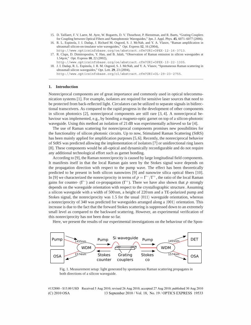
Fig. 1. Measurement setup: light generated by spontaneous Raman scattering propagates inboth directions of a silicon waveguide.
#132880 - $15.00 USD Received 5 Aug 2010; revised 26 Aug 2010; accepted 27 Aug 2010; published 30 Aug 2010(C) 2010 OSA 13 September 2010 / Vol. 18, No. 19 / OPTICS EXPRESS 19533
taneous Raman Scattering (SpRS) showing good quantitative agreement with our prediction ofnonreciprocal Raman scattering [9]. For this purpose, light generated by SpRS was measuredfrom each side of a silicon waveguide. The measurements were performed on two waveguideorientations with respect to the crystallographic axes 〈011〉 and 〈001〉 showing the predictedstrong dependence of the nonreciprocity on waveguide orientation.
2. Theory of nonreciprocal Raman gain in silicon waveguides
In this section we summarize the theory of nonreciprocal Raman gain in silicon waveguides [9].The pump and Stokes waves are assumed to propagate in waveguide modes with electric modefields p and s, respectively. The Raman interaction with the silicon is modelled using a classicallocalized polarizability model of StRS; the result can be formulated in terms of a nonlinearsusceptibility tensor χ(3) whose structure is determined by the Raman tensors of the triplydegenerate Brillouin-zone-center optical phonon in silicon [11]. The effect of the presence ofthis χ(3) on the propagating modes can be treated within full-vectorial coupled-mode theory.The power S(z) of the Stokes wave inside the waveguide is then found to evolve according todS(z)/dz = ΓP(z)S(z), where P(z) is the local pump power, and the modal gain coefficient Γ isproportional to an effective susceptibility averaged over the waveguide core, [9]
Γ =gnpns
4Z2NpNs
∫Si
{|p|2|s|2 + |p · s|2 −2(sx px)2
− 12(cos4θ +3)
[(sy py)2 +(sz pz)2]− 1
2(cos4θ −1)
[(sy pz)2 +(sz py)2]}dA, (1)
where superscripts denote cartesian components along the vertical (x), lateral (y) and longitu-dinal (z) directions (with respect to the waveguide axis), and θ is the orientation of the waveg-uide on the substrate, i. e., the angle of the waveguide axis with the 〈001〉 direction (such thatθ = 45◦ corresponds to a 〈011〉 direction). Furthermore, np,s are the refractive indices of sili-con at the pump and Stokes wavelengths, Z is the vacuum impedance, and Np,s are the usualmode-normalization integrals. Finally, g is the bulk Raman-gain constant of silicon.
Equation (1) has been written assuming the convention [12] that the mode fields have realtransverse (x,y) and imaginary longitudinal (z) field components. Now, it is a well-known prop-erty of waveguide modes that a reversal of the mode propagation direction also reverses therelative phase between transverse and longitudinal mode-field components—mathematically,the direction reversal corresponds to a complex conjugation of the mode field [12]. When per-forming this conjugation in Eq. (1), we see that the second term (|p · s|2) under the integral inEq. (1) changes, since in general |p ·s|2 �= |p∗ ·s|2 due to the presence of imaginary longitudinal(z) mode-field components pz and sz. Only when these components are negligible (such as in ribwaveguides with dimensions larger than a micrometer [5,6]), then the relation |p · s|2 = |p∗ · s|2holds and Raman gain is reciprocal. The physical origin of the Raman-induced nonreciprocityformally derived above is that the strength of the force that drives the optical-phonon latticevibration depends on the relative propagation directions of the pump and Stokes waves as dis-cussed in [9].
In our experiments reported here, we use silicon photonic wires of such small cross-sectionaldimensions (see Sect. 3.2) that the longitudinal field components lead to the large nonreciproc-ities observed here (see Sect. 4).
Before proceeding, we note that Saito et al. have reported nonreciprocal Raman scatteringin waveguides made of gallium phosphide (GaP) [13,14]. The dimensions of their waveguides,however, are still so large that longitudinal mode-field components are negligibly small, yeta significant Raman nonreciprocity (of more than a factor of 10) has been observed [13, 14].
#132880 - $15.00 USD Received 5 Aug 2010; revised 26 Aug 2010; accepted 27 Aug 2010; published 30 Aug 2010(C) 2010 OSA 13 September 2010 / Vol. 18, No. 19 / OPTICS EXPRESS 19534
Saito et al. attribute this nonreciprocity to the fact that due to the polar nature of the crystal,longitudinal-optical and transverse-optical phonons in GaP are not degenerate (as they are insilicon) but have significantly different frequencies. In GaP waveguides, this difference canmanifest itself as a Raman nonreciprocity even in the absence of significant longitudinal mode-field components, in contrast to the silicon case considered in this paper.
3. Measurement Setup and Theory
3.1. Measurement Setup
As illustrated in Fig. 1, pump light at a wavelength of 1455 nm was coupled into a siliconphotonic wire. This pump generates light at a wavelength of 1574nm by SpRS that propagatesinto both directions of the waveguide. These two signals are coupled into standard single modefibers using grating couplers [15] on each side of the chip and measured by optical spectrumanalyzers (OSAs). The same couplers are used to launch the pump power into the TE mode ofthe waveguide. Pump and Stokes signals are separated from each other by wavelength-divisionmultiplexers (WDMs).
3.2. Waveguides under Test
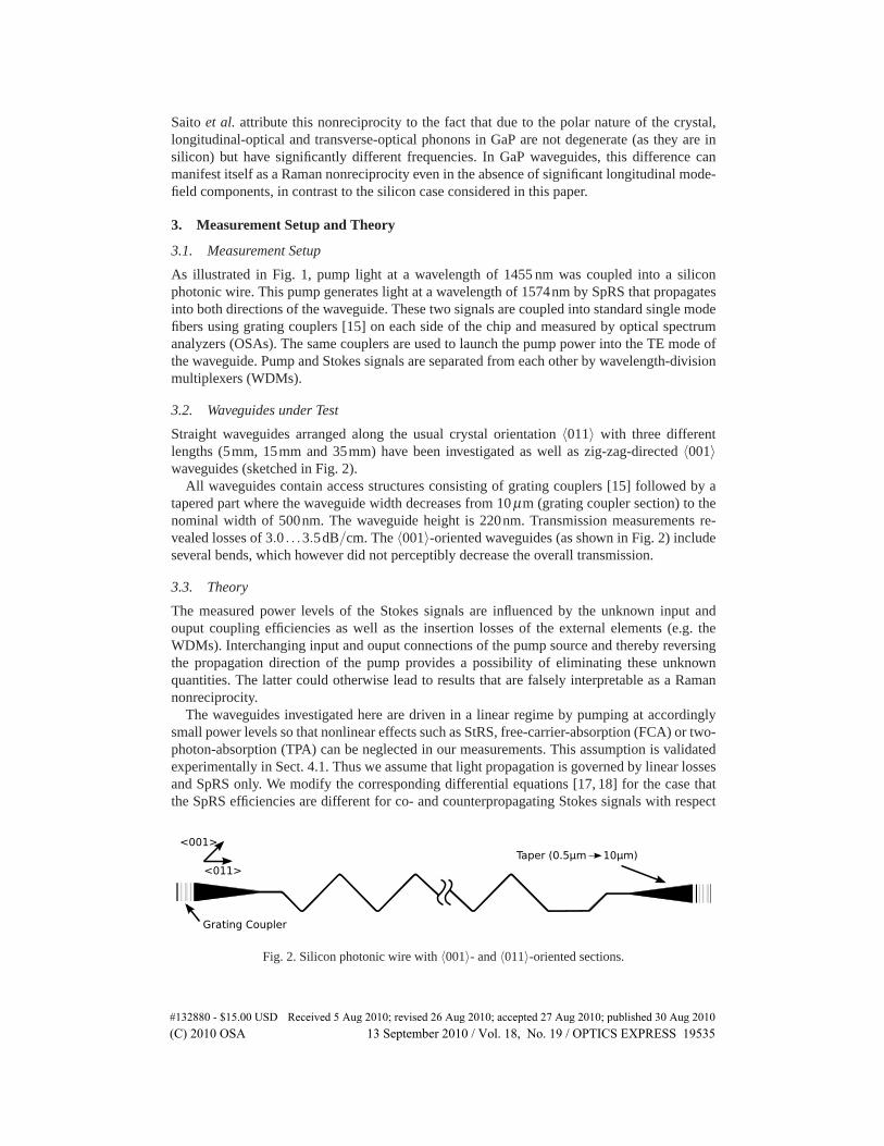
Straight waveguides arranged along the usual crystal orientation 〈011〉 with three differentlengths (5mm, 15mm and 35mm) have been investigated as well as zig-zag-directed 〈001〉waveguides (sketched in Fig. 2).
All waveguides contain access structures consisting of grating couplers [15] followed by atapered part where the waveguide width decreases from 10 μm (grating coupler section) to thenominal width of 500nm. The waveguide height is 220nm. Transmission measurements re-vealed losses of 3.0 . . .3.5dB/cm. The 〈001〉-oriented waveguides (as shown in Fig. 2) includeseveral bends, which however did not perceptibly decrease the overall transmission.
3.3. Theory
The measured power levels of the Stokes signals are influenced by the unknown input andouput coupling efficiencies as well as the insertion losses of the external elements (e.g. theWDMs). Interchanging input and ouput connections of the pump source and thereby reversingthe propagation direction of the pump provides a possibility of eliminating these unknownquantities. The latter could otherwise lead to results that are falsely interpretable as a Ramannonreciprocity.
The waveguides investigated here are driven in a linear regime by pumping at accordinglysmall power levels so that nonlinear effects such as StRS, free-carrier-absorption (FCA) or two-photon-absorption (TPA) can be neglected in our measurements. This assumption is validatedexperimentally in Sect. 4.1. Thus we assume that light propagation is governed by linear lossesand SpRS only. We modify the corresponding differential equations [17, 18] for the case thatthe SpRS efficiencies are different for co- and counterpropagating Stokes signals with respect
Grating Coupler
Taper (0.5µm 10µm)<001>
<011>
Fig. 2. Silicon photonic wire with 〈001〉- and 〈011〉-oriented sections.
#132880 - $15.00 USD Received 5 Aug 2010; revised 26 Aug 2010; accepted 27 Aug 2010; published 30 Aug 2010(C) 2010 OSA 13 September 2010 / Vol. 18, No. 19 / OPTICS EXPRESS 19535
to the pump:
dSf(z)dz
= −αSf(z)+q+(z) ·Pf(z)+q−(z) ·Pb(z) , (2)
−dSb(z)dz
= −αSb(z)+q−(z) ·Pf(z)+q+(z) ·Pb(z) , (3)
Sf(0) = 0 , (4)
Sb(�) = 0 . (5)
Here, � is the waveguide length and α are the waveguide losses which are assumed equalat the pump and Stokes wavelengths. Sf,b(z) and Pf,b(z) represent the Stokes signal and pumppowers propagating in forward (f) and backward (b) direction. Finally, q−(z) and q+(z) are thez-dependent SpRS efficiencies for counterpropagation (−) and copropagation (+) of pump andStokes waves, respectively.
In order to solve these equations we assume the pump waves inside the waveguides to beattenuated only by the linear waveguide losses and write
Pf(z) = ηLP ·P0 exp(−αz) , (6)
Pb(z) = ηRP ·P0 exp{−α(�− z)} . (7)
Here, P0 is the nominal pump power provided by the laser source, while ηL,RP accounts for the
coupling efficiencies for the pump when launched from the left-hand (L) or the right-hand (R)side of the waveguide. In the case, that either a forward-propagating pump Pf (z) or backward-propagating pump Pb(z) is present, we obtain
SLL = ηL
S ·Sb(0) = ηLS ηL
P ·P0 ·∫ �
0q−(z) · exp(−2αz)dz , (8)
SLR = ηR
S ·Sf(�) = ηRS ηL
P ·P0 · exp(αz)∫ �
0q+(z)dz , (9)
SRR = ηR
S ·S f (�) = ηRS ηR
P ·P0 ·∫ �
0q−(�− z) · exp(−2αz)dz , (10)
SRL = ηL
S ·Sb(0) = ηLS ηR
P ·P0 · exp(αz)∫ �
0q+(�− z)dz . (11)
The SL,RL are the out-coupled Stokes powers at the left-hand waveguide end when the pump
power was launched from the left (L) or the right (R) side, respectively, while the SL,RR are the
corresponding Stokes powers measured at the right-hand waveguide end. The ηL,RS account for
the out-coupling efficiencies of the Stokes signals on each side of the waveguide.We define a total SpRS imbalance as
I =
√SL
L ·SRR
SLR ·SR
L= exp(α�) ·
√∫ �0 q−(z) · exp(−2αz)dz
∫ �0 q−(�− z) · exp(−2αz)dz
∫ �0 q+(z)dz
, (12)
where the unknown coupling efficiencies as well as the nominal pump power P0 no longerappear.
3.4. Imbalance for constant waveguide orientation and cross section
For the first interpretation of our measurements we neglect any change in waveguide width(tapered section) or orientation along z. The SpRS efficiencies can then be assumed constant,
#132880 - $15.00 USD Received 5 Aug 2010; revised 26 Aug 2010; accepted 27 Aug 2010; published 30 Aug 2010(C) 2010 OSA 13 September 2010 / Vol. 18, No. 19 / OPTICS EXPRESS 19536
q±(z) = q± = const., and Eq. (12) simplifies to
I = Iα ·ρ . (13)
Here, on the one hand,
Iα =1− exp(−2α�)2α� · exp(−α�)
=sinhα�
α�(14)
is the loss-induced imbalance that quantifies the well-known imbalance between forward andbackward spontaneous Stokes powers which is caused by the presence of linear waveguidelosses alone, even if the Raman process itself was completely reciprocal [17, 18]. On the otherhand,
ρ =q−
q+ (15)
is our sought-after Raman nonreciprocity. In view of potential applications for nonreciprocalcomponents [7, 8] it should be noted that the spontaneous Raman efficiencies q± are directlyproportional to the stimulated Raman-gain coefficients Γ± discussed in [9], and the SpRS non-reciprocity q−/q+ is identical to the StRS nonreciprocity Γ−/Γ+.
It should be noted here, that the waveguide orientation of our nominal 〈001〉 zig-zag struc-ture is not constant as it includes 〈011〉-oriented access waveguides as well as several bends(see Fig. 2). To begin with, however, we will neglect the corresponding change of q± in theevaluation of our measured data (Sect. 4.2). Afterwards, we will involve the change of q± inSect. 4.3 and calculate the total imbalance to be expected in our mixed-oriented waveguidesaccording to Eq. (12).
To sum up, the measurement of the four Stokes powers SL,RL,R together with the knowledge
of the linear waveguide losses α from independent measurements (see Sect. 3.2) provides amethod of determining the Raman-induced nonreciprocity ρ where the influence of unknowncoupling efficiencies is eliminated.
4. Results
4.1. Measurement technique and confirmation of linearity
Figure 3 shows measured Stokes spectra (solid curves) for three different nominal pump powersP0 for forward [Fig. 3(a)] and backward [Fig. 3(b)] scattering. To evaluate this measurement wecalculated the corresponding Lorentzian fits (dashed curves). The FHWM of this fit is 102±5.2GHz (throughout all our measurements), as expected from Raman scattering in silicon [17].Furthermore, Fig. 3(b) shows a pump-power-dependent noise floor that is caused by backwardSpRS in the feeding silica fiber; our fitting ansatz includes such a constant offset.
We injected the pump at the left-hand side here and estimated an in-coupled pump power of2mW, whereas the nominal pump power was set to P0 = 200mW. This poor coupling efficiencywas caused by the bandwidth limitation of the grating couplers [15]. The wavelength withmaximum coupling efficiency could be tuned to a desired wavelength by tilting the feedingfiber to an appropriate angle with respect to the grating coupler plane. However, we optimizedthis arrangement for maximum Stokes coupling efficiency, so that we can reliably detect theweak Stokes signals expected here.
From the measurements of Fig. 3 we obtain the total SpRS power emitted from the siliconwaveguide by integrating only over the Lorentzian portion of the fit. The total forward- (SL
R)and backward- (SL
L) scattered Raman powers as a function of the nominal pump power P0 areshown in Fig. 4 as circles and crosses, respectively.
Before proceeding, we note that Fig. 4 also shows the residual pump power detected at theright-hand waveguide end (as stars). The observed nearly linear dependence of all three powers
#132880 - $15.00 USD Received 5 Aug 2010; revised 26 Aug 2010; accepted 27 Aug 2010; published 30 Aug 2010(C) 2010 OSA 13 September 2010 / Vol. 18, No. 19 / OPTICS EXPRESS 19537
1572 1573 1574 1575 1576Wavelength [nm]
Spec
tral d
ensi
ty [p
W/n
m]
1572 1573 1574 1575 15760
5
10
15
20
Wavelength [nm]
(b) backward SpRS(a) forward SpRS
P = 200 mW
125 mW
80 mW
P = 200 mW
125 mW
80 mW
0
5
10
15
2000
Fig. 3. (a) Forward, and (b) backward spontaneous Stokes spectra for three different nom-inal pump powers P0 in a 5-mm-long 〈011〉 waveguide. Solid curves: experimental data;dashed curves: fit (Lorentzian and offset).
0 25 50 75 100 125 150 175 2000
10
20
30
Nominal pump power P [mW]
Det
ecte
d po
wer
s
transmitted pump [µW]
forward Stokes [pW]
backward Stokes [pW]
Fig. 4. Stars: pump power transmitted through a 5-mm-long 〈011〉 waveguide versus nom-inal pump-laser power P0. Circles and crosses: corresponding forward and backward spon-taneous Raman powers, respectively. Lines are zero-offset linear fits to the experimentaldata. The laser used did not permit setting its output power P lower than 80mW.
in Fig. 4 on the nominal pump power suggests that nonlinear effects such as StRS, TPA andFCA are not significant at the power levels used here. Indeed, the estimated in-coupled pumppower of at most 2mW is much lower than the power levels at which StRS has been observedin comparable waveguides before [16]. This supports the validity of our model Eqs. (2)–(5).
Without taking into account the non-zero waveguide losses as well as the (unknown) couplingefficiencies (see Sect. 3.1) the results shown in Fig. 4 would lead to a total imbalance of I = 1.6(that could be interpreted as a nonreciprocity).
However, this imbalance could also be induced by linear losses and differing coupling ef-ficiencies alone as mentioned above. Therefore, an extended measurement method should beapplied as shown in the next section to exclude the loss-caused imbalance Iα as well as theunknown coupling efficiencies from the measured data by applying Eqs. (12)–(15).
4.2. Measurement results
In order to extract the net Raman nonreciprocity from the measured Stokes powers [by applyingEq. (13)] we performed the four measurements corresponding to Eqs. (8)–(11) on a total of27 waveguides with different lengths and orientations. The nominal pump power was kept atP0 = 200mW which made sure that the recorded Stokes spectra were sufficiently above thenoise floor (see Fig. 3) and that we are still in the linear regime where StRS, TPA and FCAare negligible (see Fig. 4). The evaluation was done according to the procedure explained inSect. 3.4.
Figure 5 shows the results after taking the four measurements SL,RL,R for each of the 27 waveg-
#132880 - $15.00 USD Received 5 Aug 2010; revised 26 Aug 2010; accepted 27 Aug 2010; published 30 Aug 2010(C) 2010 OSA 13 September 2010 / Vol. 18, No. 19 / OPTICS EXPRESS 19538
Fig. 5. Measured data for 27 waveguides from the same chip (five groups of nominally iden-tical waveguides; layout sketched above each group, not to scale). Squares: measured SpRSimbalance I = ρ · Iα . Crosses: loss-induced imbalance Iα , assuming 3.5dB/cm waveguideloss. Diamonds: sought-after Raman nonreciprocity ρ = q−/q+ = I/Iα .
uides. The total imbalance I is plotted as squares in Fig. 5. It contains the Raman-inducednonreciprocity ρ as well as the linear-loss-based imbalance Iα [see Eq. (13)]. The latter iscalculated assuming losses of 3.5dB/cm (see Sect. 3.2) for all measured waveguides and is in-dicated as crosses in Fig. 5. Correcting I from the loss-induced imbalance by means of dividingit by Iα yields the sought-after Raman nonreciprocity ρ = I/Iα = q−/q+ shown as diamondsin Fig. 5.
Looking closer to the rightmost waveguides (#25 - #27 in Fig. 5), an imbalance of I = 4.79±0.69 can be seen. The waveguide length here is 35mm yielding a loss-induced imbalance Iα =2.96. Dividing I by Iα ends up in a Raman nonreciprocity of ρ = 1.62± 0.23 (diamonds inFig. 5). This shows good agreement to our theoretically predicted value of 1.5 from [9].
Waveguides #13 - #24 in Fig. 5 have smaller lengths of 15mm and 5mm but the same ori-entation (〈011〉). It can be seen that the corresponding imbalances decrease to 2.06±0.07 and1.67±0.11, respectively. Excluding Iα (which also decreased) yields a Raman nonreciprocityof about 1.6 again.
The pure Raman nonreciprocity ρ of all these 〈011〉-oriented waveguides (#13 - #27) doestherefore not depend on the waveguide length as it was expected from our previous analysis. Infact, we read a common Raman nonreciprocity of ρ = 1.63±0.12 for these waveguides.
Performing the measurements on partly 〈001〉-oriented waveguides leads to the results shownon the left side of Fig. 5 (waveguides #1−#12). Here, a total imbalance > 4 could be measuredagain. The lengths of these waveguides are only 6−7mm leading to an Iα that is close to unity.The measured total imbalance I can therefore only be due to a strong Raman nonreciprocityρ . Comparing the mixed-oriented waveguides (#6 - #12) to the almost pure 〈001〉-orientedwaveguides (#1 - #5) the Raman nonreciprocity increases from 2.31± 0.27 to 4.35± 0.29.However, in contradiction to this result we calculated a Raman nonreciprocity of 340 for a pure〈001〉 orientation as calculated in [9]. For this reason, the following section will give a moredetailed analysis on the nonreciprocity to be expected in our partly 〈001〉-oriented waveguides,which will resolve this remaining discrepancy.
4.3. Calculation of total imbalance for waveguides with mixed 〈001〉 and 〈011〉 orientation
Due to design-given fixed positions of the 〈011〉-oriented access waveguide structures (seeFig. 2) a pure orientation along only a 〈001〉 crystallographic axis could not be realized. Asshown in Fig. 2 only the zig-zag part of the structure is 〈001〉-oriented. Grating coupler, waveg-uide taper section as well as the small horizontal part on the right hand side of the structure arestill 〈011〉-oriented. The Raman nonreciprocity for a pure 〈011〉 orientation can be calculatedas 1.5 whereas a pure 〈001〉 orientation leads to a nonreciprocity of 340 [9]. The 〈011〉 sectionsin our mixed structure prevent the total forward Stokes scattering of the whole waveguide from
#132880 - $15.00 USD Received 5 Aug 2010; revised 26 Aug 2010; accepted 27 Aug 2010; published 30 Aug 2010(C) 2010 OSA 13 September 2010 / Vol. 18, No. 19 / OPTICS EXPRESS 19539
being suppressed down to the extremely low level expected for a pure 〈001〉 waveguide [9].The measured nonreciprocity in our zig-zag waveguides was therefore far below the value of340 expected for a pure 〈001〉 orientation. To examine the theoretical Raman nonreciprocityoccurring in our mixed-oriented structures we calculated the expected imbalances I for forwardand backward pumping. Here, we used the general result of Eq. (12), where the Raman nonre-ciprocity can not be extracted from the total imbalance as it was possible with Eqs. (13)–(15).We will therefore compare the theoretical imbalance to our measured imbalance here insteadof evaluating an explicit Raman nonreciprocity as done in Sect. 4.2.
To obtain an accurate value for the total imbalance I we calculated the local values of q±(z)at each position z of our waveguide. Here, we considered the change of waveguide width andorientation as in [9]. As mentioned above, the latter differs between the access-waveguides(〈011〉) and the zigzag-directed structure (〈001〉). We also included the change of orientationwithin each bend in the calculation of q±(z). The losses have been assumed to be 3.5dB/cmagain. Eq. (12) can then be solved numerically and leads to an imbalance I = 4.92. This is closeto our measured value of I = 4.59± 0.31 (squares at waveguides #1 - #5 in Fig. 5). Note thateven if our waveguide would be loss-free, the calculated imbalance would be still 4.67 which isfar from unity and can only be caused by the Raman-induced nonreciprocity. We repeated thiscalculation for waveguides #6 - #12, where only half of the structure is 〈001〉-oriented. Here,the calculated total imbalance I = 1.97 also shows reasonable agreement with the measuredvalue of 2.40±0.28.
5. Conclusions
We have experimentally shown the presence of a nonreciprocity in the spontaneous Raman scat-tering in strongly confining silicon waveguides. Evaluating measured spontaneously scatteredStokes powers from both sides of a unidirectional-pumped waveguide reveals a Raman nonre-ciprocity of 1.63 for waveguides oriented along a 〈011〉 crystallographic axis. Partly changingthis orientation to a 〈001〉 one led to a net increase of the apparent Raman nonreciprocity to4.35. While a much stronger increase (up to 340) for a pure 〈001〉 waveguide has previouslybeen predicted [9], we have shown that the value measured here is quantitatively explained bythe fact that our nominally 〈001〉-oriented waveguides actually included 〈011〉-oriented accesswaveguides.
Acknowledgments
This work was funded by the German Research Foundation (DFG) in the framework ofForschergruppe FOR 653. The samples characterized have been fabricated at ePIXfab.
#132880 - $15.00 USD Received 5 Aug 2010; revised 26 Aug 2010; accepted 27 Aug 2010; published 30 Aug 2010(C) 2010 OSA 13 September 2010 / Vol. 18, No. 19 / OPTICS EXPRESS 19540