51
13th April 2005 R.Bates, QM Measurements of Barrel and EC HEX R. Bates, M. Olcese, B. Gorski, QM for prototype builds
13th April 2005 R.Bates, QM
Measurements of Barrel and EC HEX
R. Bates, M. Olcese, B. Gorski, QM for prototype builds
13th April 2005 R.Bates, QM
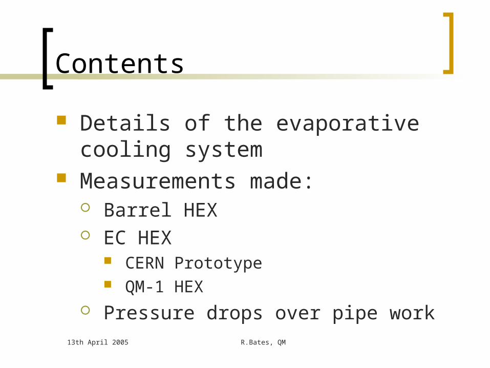
Contents
Details of the evaporative cooling system
Measurements made: Barrel HEX EC HEX
CERN Prototype QM-1 HEX
Pressure drops over pipe work

13th April 2005
The evaporative system in 175
General design of system close to final design
A’
C
F
F
P
pressureregulator
back pressure regulator
pump
condenser
oil freecompressor
heater
heatexchanger
capillary
cooling duct with detectors
liquid vapor
Free Access AreaUSA 15
Pressure Regulation Rackson the platform
UX15
Inner TrackerUX15
B
D
D’’
E
A
booster
D’
13th April 2005 R.Bates, QM
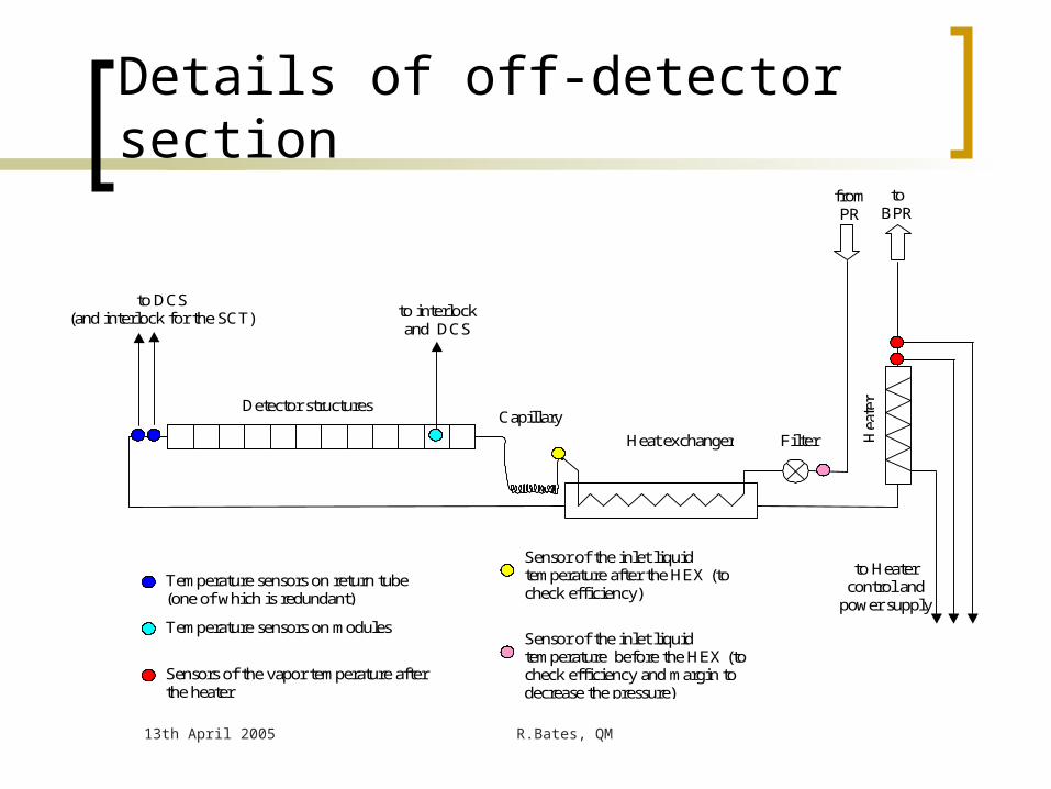
Details of off-detector section
to DCS (and interlock for the SCT)
to Heater control and
power supply
to interlock and DCS
to BPR
from PR
Temperature sensors on return tube (one of which is redundant)
Temperature sensors on modules
Sensor of the inlet liquid temperature after the HEX (to check efficiency)
Sensors of the vapor temperature after the heater
Heat exchanger
Detector structures
Hea
ter
Filter
Capillary
Sensor of the inlet liquid temperature before the HEX (to check efficiency and margin to decrease the pressure)

13th April 2005 R.Bates, QM
Detail of circuit tested Volume and Danfoss
meters for massflow measurements
Heat liquid after Danfoss to reach 35°C before HEX inlet Manual heater control
PLC controlled proto-heater
ELMBs with PVSS monitoring plus some manometer duplication
Keller high pressure transducer before capillary
Vapor returnHeater
PCap
Condenser
BPR
PR
Volume flowmeter
Compressor
PvaHEX
PlaCap
PvbBPR
PlHEX
PinFM
TlbHEX0
TvaHEX
TvbHEX
TinFM
TvaH
Mass flowmeter
Watercooled
HEXInlet
liquidHeater
TlbHEX1Barrel HEX
Heater representingdetector structures
TlaCap0
PlbCap
PlbHEX
TlbCap1
TlbCap0
PvHEX
TlaHEX1
TlaHEX0
Capillaries
TlaCap1

13th April 2005 R.Bates, QM
Enthalpy Diagram
A
A’
BC
D
D”
D’
E
FF’
D1”
E1
subcoolingSub-cooling
Boiling in the cooling circuit
Final Heater
Compression
Condensation
Pumping
Subcooling increases efficiency,
i.e. less flow required
Expansion in the capillary
Psat=exp(T)

13th April 2005 R.Bates, QM
Why sub-cooling
Cooling power = massflow x Enthalpy Max Enthalpy at -25 °C = 102 J/g No sub-cooling, liquid temp = 35°C
Power = massflow x 36 J/g : Endcap 9.6g/s, Barrel 14g/s No sub-cooling, liquid temp = 20 °C
Power = massflow x 53.7 J/g : Endcap 6.5g/s , Barrel 9.5g/s Sub-cooling to -10 °C
Power = massflow x 86.1 J/g Massflow reduction up to 2.4 times! Slightly lower as require Xu = 0.9 to cool inlet liquid in HEX
Endcap (35°C) = 5.7g/s, Barrel 7.8g/s Reduce the change in massflow as a function of TlbHEX
No sub-cooling 50% increase in massflow Sub-cooling <10% increase (small change in TlbCAP)
13th April 2005 R.Bates, QM
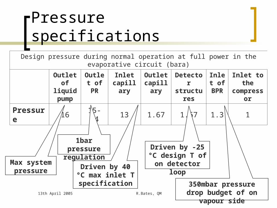
Pressure specificationsDesign pressure during normal operation at full power in the evaporative circuit (bara)
Outlet of liquid pump
Outlet of PR
Inlet capillary
Outlet capillary
Detector structures
Inlet of
BPR
Inlet to the compressor
Pressure 16 15-14 13 1.67 1.67 1.3 1
Max system pressure
Driven by 40 °C max inlet T
specification
Driven by -25 °C design T of on detector loop
350mbar pressure drop budget of on vapour side
1bar pressure regulation
13th April 2005 R.Bates, QM
HEX & massflow
HEX efficiency (and Massflow) must be sufficient to cool system with full power
Must cope with TlbHEX = 20°C to 35°C Sudden power changes in detector structures
Limited increase in Massflow as a function of TlbHEX Detector power
Vapour pressure drops to be as small as possible (50mbar)

13th April 2005 R.Bates, QM
Heat Exchangers Design is different for the three sub-detectors due to
different layout and geometrical constraints All countercurrent type Pixel: parallel type external. Al inlet and return tubes
glued together over 1.5m. Simple design, possible with small power load
EC SCT: inlet tube is coiled in spiral inside the return tube over less than 0.4m.
Barrel SCT: parallel type internal. Two inlet tubes are routed inside the return tube over a length of 1.5m and parallel to the return tube axis

13th April 2005 R.Bates, QM
SCT EC heat exchangers Several
prototypes made
Final design qualified
Pressure drop budget is met
QMUL is making a final prototype with final tubes

13th April 2005 R.Bates, QM
Endcap HEX - designs
1st failed due to boiling inside capillary HEX1 – HEX3 failed due to low efficiency
HEX name Design type Internal pipe Vapour return
Length (mm)
ID (mm)
OD (mm)
Length (mm)
ID (mm)
Free ID (mm)
HEX Capillary inside HEX 500 10 7.6
HEX1 CuNi pipe inside HEX 900 2.0 2.4 442 12 7.2
HEX2 CuNi pipe inside HEX 1900 2.0 2.4 380 12 7.2
HEX3 Cu pipe inside HEX 1900 2.0 3.0 380 14 8.0
HEX4 Cu pipe inside HEX 3000 2.0 3.0 380 14 8.0
QM-1 Cu pipe inside HEX 2764 2.0 3.0 361 14 8.0

13th April 2005 R.Bates, QM
Results with CERN HEX4
Minimum massflow to remove nominal detector power of 346.5W found for HEX = 5.7g/s
Inlet liquid temperature of 35°C maintained through out Massflow measured by volume meter Massflow measurement checked with energy balance
Know inlet liquid and outlet vapour pressure/temperature Know power into the system Can calculate massflow

Minimum massflow
Minimal massflows at 100% power
5.2
5.3
5.4
5.5
5.6
5.7
5.8
5.9
6
20 25 30 35 40 45
Temperature at HEX inlet (C)
Ma
ss
flo
w (
g/s
)
TlaHEX = -12.3 C
TlaHEX = -12.9 C
TlaHEX = -12.7 C
TlaHEX = -14.2 C
TlaHEX = -8.7 C
TlaHEX = -3.2 C
TlaHEX = -6.5 C
TlaHEX = -20.7 C
TlaHEX = -16.1 C
TlaHEX = -19.9 C
35 ºC basepoint:TlaHEX = -12.8 ºC
Baseline massflow = 5.7g/sfor TlbHEX = 35°C, 100% power

13th April 2005 R.Bates, QM
Results summary– CERN HEX4
TlbHEX=35C
100% power
TlbHEX=20C
0% power
Massflow (g/s)
5.7 5.74
TlaHEX -12.8 -25
Hex eff 0.81 1.0
Xi 0.17 0.1
Xu 0.76 0.1
Massflow Increase= 0.7%
13th April 2005 R.Bates, QM
Stability checks
Tests were performed to confirm that the system is stable Ran for more than 2 hours without
interference Rapidly (less than 1 minute) increase
detector power from 0 to 100% Repeated measurements to confirm
observations
13th April 2005 R.Bates, QM
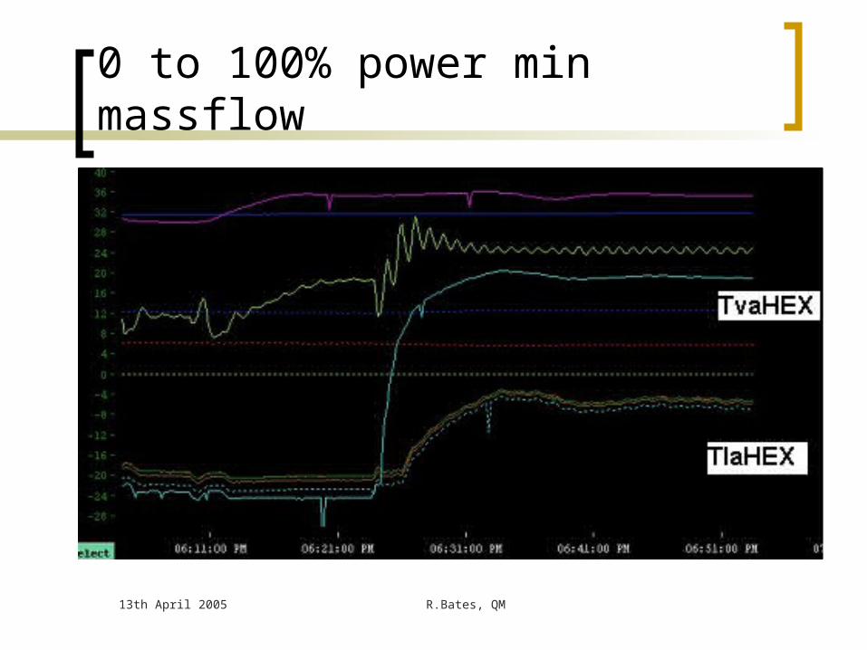
0 to 100% power min massflow

Different HEX orientations
All with TlbHEX = 35°C, 100% power
V
min massflow (g/s) 5.5 5.7 5.4
PlbCAP (bara) 14.2 14.25
TlaHEX (°C) -15 -13 -6.5
Efficiency (%) .83 .80 .69
Xi 0.13 0.17 0.22
Xu 0.74 0.76 0.83
-45deg
V
L V +45deg
L
13th April 2005 R.Bates, QM
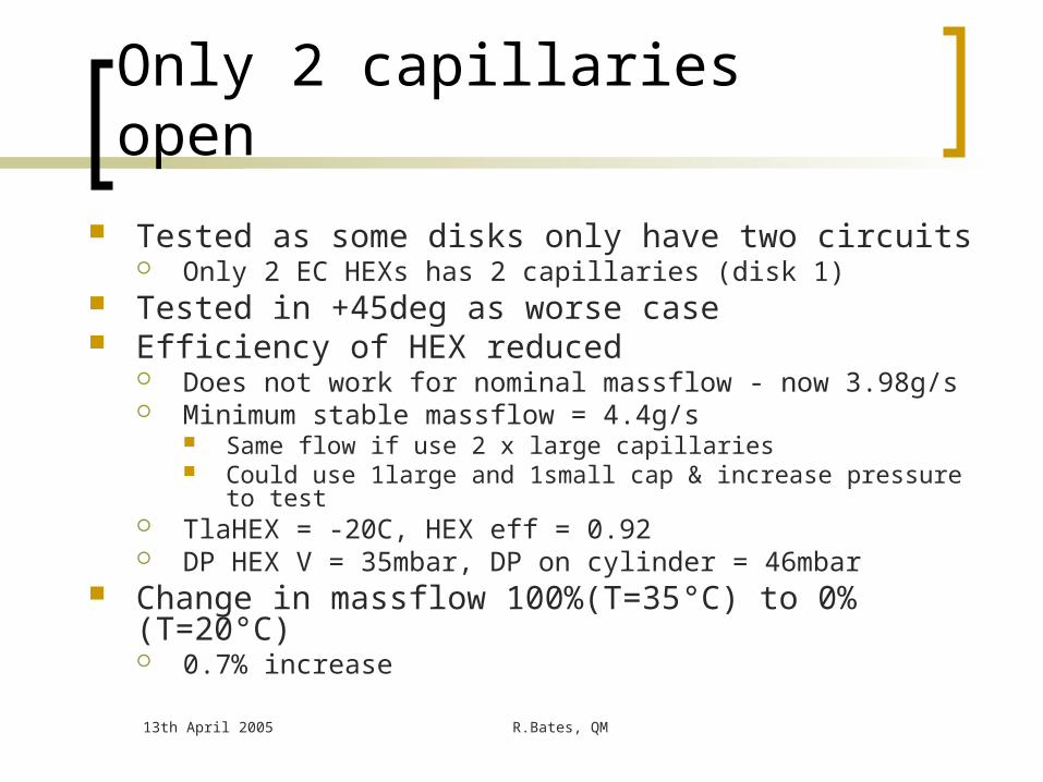
Only 2 capillaries open
Tested as some disks only have two circuits Only 2 EC HEXs has 2 capillaries (disk 1)
Tested in +45deg as worse case Efficiency of HEX reduced
Does not work for nominal massflow - now 3.98g/s Minimum stable massflow = 4.4g/s
Same flow if use 2 x large capillaries Could use 1large and 1small cap & increase pressure to test
TlaHEX = -20C, HEX eff = 0.92 DP HEX V = 35mbar, DP on cylinder = 46mbar
Change in massflow 100%(T=35°C) to 0%(T=20°C) 0.7% increase

13th April 2005 R.Bates, QM
QM-1
Inlet liquid pipelength reduced by8% to 2764mm
100% power
TlbHEX=35C
CERN HEX, 0deg
+45deg -45deg -45deg -45deg0%, TlbHEX=20C
Massflow 5.7 5.84 5.99 5.8 6.16 (+3%)
PlbCAP n/a 13.08 13.01 12.59 13.0
TlaHEX -12.8 -9.1 -7.6 -7.5 -14
Hex eff 0.81 .75 .72 .72 .92
Xi 0.17 .18 .22 .22 .11
Xu 0.76 .74 .78 .79 .11
Stable at 98% power and massflow of 5.84g/s (2.5% above baseline 5.7g/s)Max massflow 8% above baseline massflow: (+45deg, 0%(T=20) = 6.06g/s)

13th April 2005 R.Bates, QM
Barrel HEX
Contra-flow Two liquid inlet pipes Length 1.5m
Thermal enclosure bulk head
Heat exchanger
Heater
Demountable connector + electrical break
Demountable connector
Demountable connector + electrical break + filter
Return tube
Inlet tube
Capillary
Schematic 1: SCT barrel layout of cooling circuit from stave to heater
Vapour in
45
HEX out of page
x
z
-45deg geometry

13th April 2005 R.Bates, QM
Results
Nominal massflow of 7.8g/s shown to remove nominal detector power of 504 W
Inlet liquid temperature of 35°C maintained through out
Stability checks performed System measured for both ± 45deg Tested with cooling loop & barrel 6 manifold HEX vapour ΔP too high – but manageable

13th April 2005 R.Bates, QM
Results
100% power (504W)
TlbHEX = 35C
+45deg geometry -45deg geometry
Massflow (g/s) 7.8 7.8
TlaHEX (oC) 9.5 9.2
HEX Efficiency 0.43 0.44
Xi 0.34 0.34
Xu 0.98 0.98
P vapour (mbar) 145 140
P liquid (mbar) 120 130
Pressure after Cap 1.81 1.84
13th April 2005 R.Bates, QM
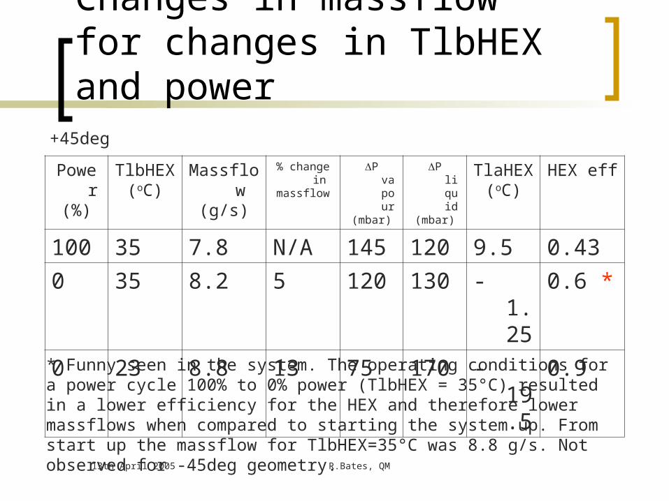
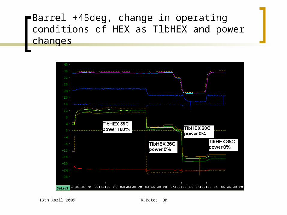
Changes in massflow for changes in TlbHEX and power
Power(%)
TlbHEX(oC)
Massflow(g/s)
% change inmassflow
P vapour(mbar)
P liquid(mbar)
TlaHEX(oC)
HEX eff
100 35 7.8 N/A 145 120 9.5 0.43
0 35 8.2 5 120 130 -1.25 0.6 *
0 23 8.8 13 75 170 -19.5 0.9
* Funny seen in the system. The operating conditions for a power cycle 100% to 0% power (TlbHEX = 35°C) resulted in a lower efficiency for the HEX and therefore lower massflows when compared to starting the system up. From start up the massflow for TlbHEX=35°C was 8.8 g/s. Not observed for -45deg geometry.
+45deg
13th April 2005 R.Bates, QM
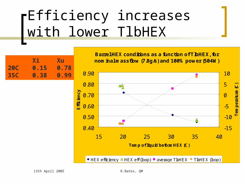
Efficiency increases with lower TlbHEX
Barrel HEX conditions as a function of TlbHEX, for nominal massflow (7.8g/s) and 100% power (504W)
0.40
0.50
0.60
0.70
0.80
0.90
15 20 25 30 35 40
Temp of liquid before HEX (C)
Eff
icie
nc
y
-15
-10
-5
0
5
10
Te
mp
era
ture
(C
)
HEX efficiency HEX eff (loop) average TlaHEX TlaHEX (loop)
Xi Xu20C 0.15 0.7835C 0.38 0.99
13th April 2005 R.Bates, QM
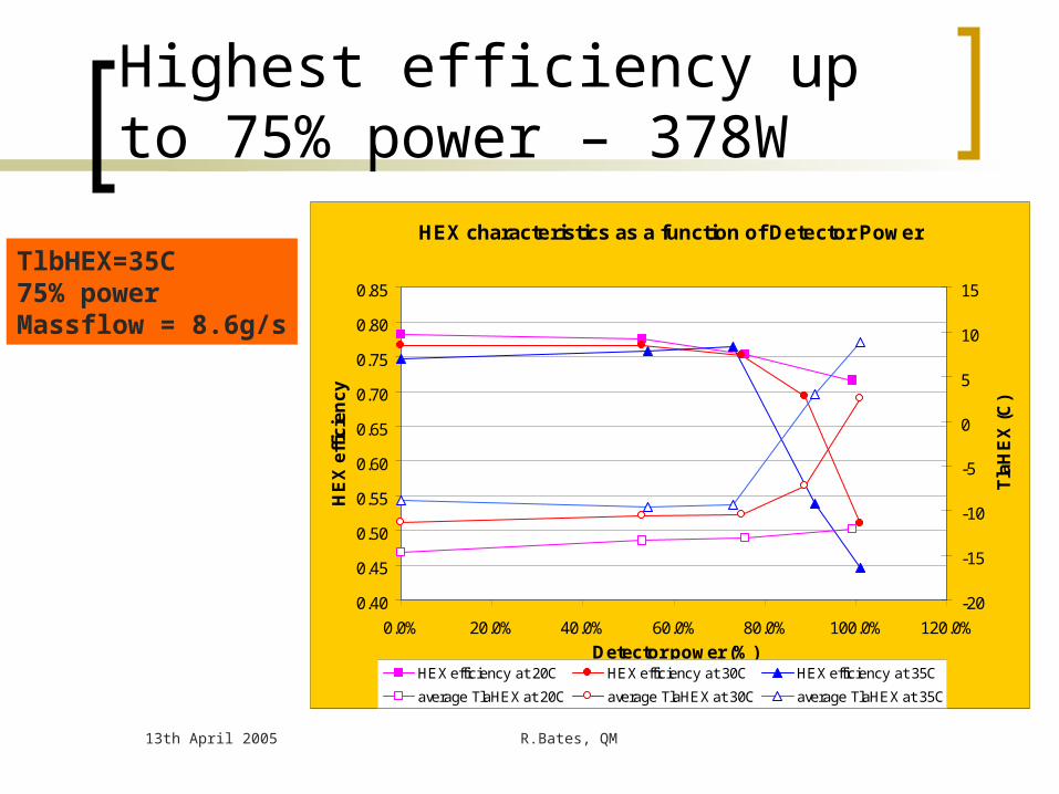
Highest efficiency up to 75% power – 378W
HEX characteristics as a function of Detector Power
0.40
0.45
0.50
0.55
0.60
0.65
0.70
0.75
0.80
0.85
0.0% 20.0% 40.0% 60.0% 80.0% 100.0% 120.0%
Detector power (%)
HE
X e
ffic
ien
cy
-20
-15
-10
-5
0
5
10
15
Tla
HE
X (
C)
HEX efficiency at 20C HEX efficiency at 30C HEX efficiency at 35C
average TlaHEX at 20C average TlaHEX at 30C average TlaHEX at 35C
TlbHEX=35C75% powerMassflow = 8.6g/s
13th April 2005 R.Bates, QM
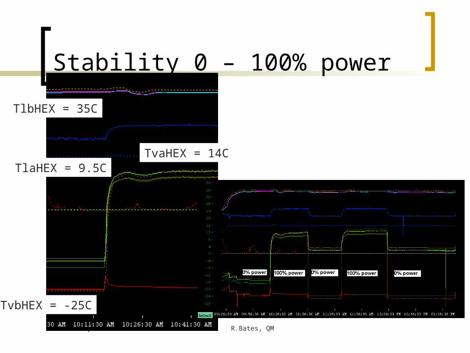
Stability 0 – 100% power
TlaHEX = 9.5C
TlbHEX = 35C
TvbHEX = -25C
TvaHEX = 14C

13th April 2005 R.Bates, QM
2hour run
13th April 2005 R.Bates, QM
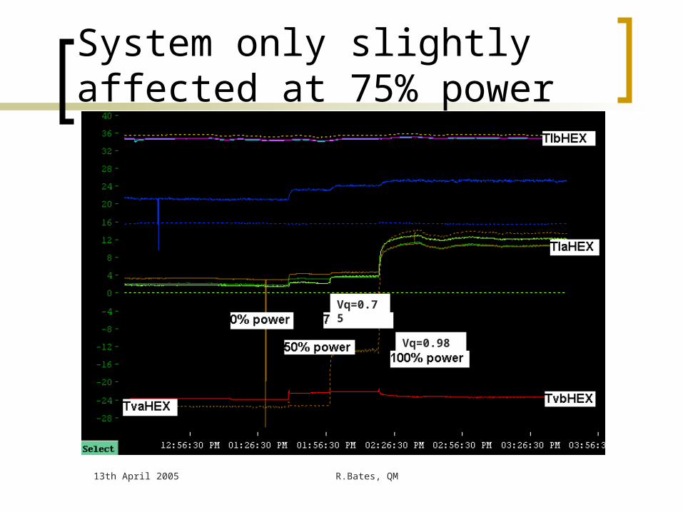
System only slightly affected at 75% power
Vq=0.75
Vq=0.98
13th April 2005 R.Bates, QM
Barrel HEX with cooling loop
Vapour returnHeater
PCap
BPR
PvaHEX
PlaCap
PvbBPR
PlHEX
TlbHEX0
TvaHEX
TvaH
TlbHEX1Barrel HEX
Barrel cooling loop
TlaCap0
PlbCap
PlbHEX
TlbCap1
TlbCap0
PvHEX
TlaHEX1
TlaHEX0
Capillaries
TlaCap1
PvaLoop
TlaMod24
TlbMod1
TvbHEX
TlbMod1
TlaMod24
PLoop
PvbHEX
Liquid fromcooling rig
Vapour tocooling rig

13th April 2005 R.Bates, QM
Barrel HEX with cooling loopPlaCap
TlaCap0
TvbHEX
Capillary
TlaCap1
PvaLoop
TlaMod24
TlbMod1
PLoop Capillary
To HEX
TlaMod1
TlaMod24
TlbMod1 TlaMod1
TlaMod24 TlaMod24
M2
M3
M1
M7
M8
M6
M11
M12
M10
M2
M3
M1
M7
M8
M6
M11
M12
M10
M23
M22
M24
M18
M17
M19
M14
M13
M15
M23
M22
M24
M18
M17
M19
M14
M13
M15
TlaMod12
TlaMod12

13th April 2005 R.Bates, QM
Barrel HEX/Cooling loop test
Tested HEX with real cooling loop HEX performance the same with cooling
loop as with dummy load Cools first and final module Pressure drop over cooling loop
considerable – results in evaporation temperature changes
ΔP less for lower detector power and lower inlet liquid temperature
13th April 2005 R.Bates, QM
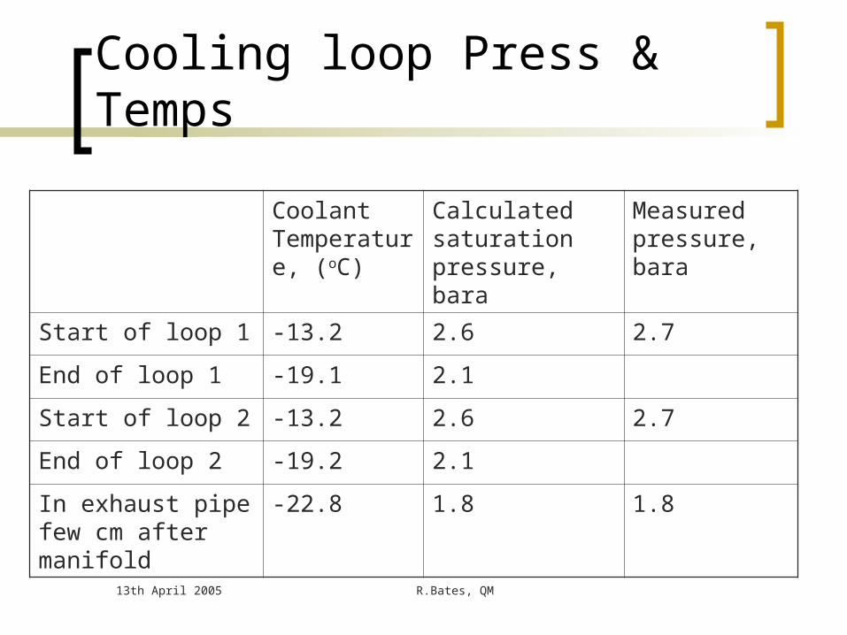
Cooling loop Press & Temps
Coolant Temperature, (oC)
Calculated saturation pressure, bara
Measured pressure, bara
Start of loop 1 -13.2 2.6 2.7
End of loop 1 -19.1 2.1
Start of loop 2 -13.2 2.6 2.7
End of loop 2 -19.2 2.1
In exhaust pipe few cm after manifold
-22.8 1.8 1.8
13th April 2005 R.Bates, QM
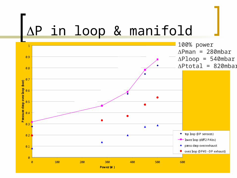
P in loop & manifold
0
0.1
0.2
0.3
0.4
0.5
0.6
0.7
0.8
0.9
1
0 100 200 300 400 500 600
Power (W)
Pre
ssu
re d
rop
ove
r lo
op
(b
ar)
top loop (DP sensors)
lower loop (diff 2 PAbs)
press drop over exhaust
over loop (DP#3 - DP exhaust)
Massflow 7.9VQ in 0.35VQ out 0.98
Massflow 8.7VQ in 0.19VQ out 0.19
Massflow 8.6VQ in 0.16VQ out 0.49
Massflow 8.7VQ in 0.17VQ out 0.61
Massflow 8.1VQ in 0.29VQ out 0.86
100% powerPman = 280mbarPloop = 540mbarPtotal = 820mbar
13th April 2005 R.Bates, QM
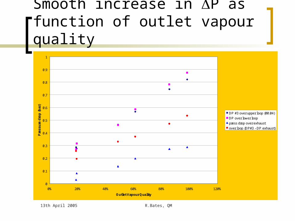
Smooth increase in P as function of outlet vapour quality
0
0.1
0.2
0.3
0.4
0.5
0.6
0.7
0.8
0.9
1
0% 20% 40% 60% 80% 100% 120%
Outlet Vapour Quality
Pre
ssu
re d
rop
(b
ar)
DP #3 over upper loop (00.04)
DP over lower loop
press drop over exhaust
over loop (DP#3 - DP exhaust)
13th April 2005 R.Bates, QM
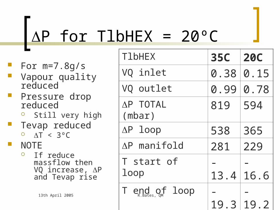
P for TlbHEX = 20ºC
For m=7.8g/s Vapour quality
reduced Pressure drop
reduced Still very high
Tevap reduced T < 3ºC
NOTE If reduce massflow
then VQ increase, P and Tevap rise
TlbHEX 35C 20CVQ inlet 0.38 0.15VQ outlet 0.99 0.78P TOTAL (mbar) 819 594P loop 538 365P manifold 281 229T start of loop -13.4 -16.6T end of loop -19.3 -19.2T (ºC) 5.9 2.6

13th April 2005 R.Bates, QM
Summary of HEX performances
Need more liquid at the outlet (higher efficiency)
for stability
Min flow cooling 100% of power with stable load transients 0%-100%-0%
50% more capacity
13th April 2005 R.Bates, QM
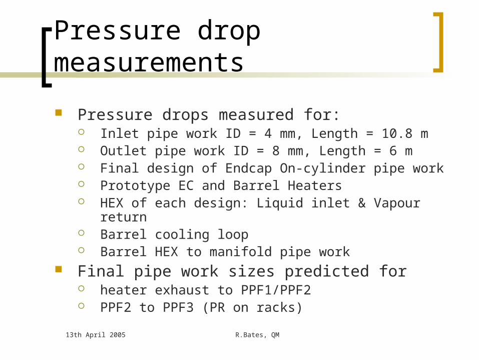
Pressure drop measurements
Pressure drops measured for: Inlet pipe work ID = 4 mm, Length = 10.8 m Outlet pipe work ID = 8 mm, Length = 6 m Final design of Endcap On-cylinder pipe work Prototype EC and Barrel Heaters HEX of each design: Liquid inlet & Vapour return Barrel cooling loop Barrel HEX to manifold pipe work
Final pipe work sizes predicted for heater exhaust to PPF1/PPF2 PPF2 to PPF3 (PR on racks)

EC Pressure drops - summaryFrom To Length (mm) ID (mm) Pressure drop (mbar)
Inlet
PP3 PP2 25000 6 45.9
PP2 PPF1 6000 4 55.8
PPF1 Inlet of HEX 800 3 23.5
HEX 3000 2 1000 (1200)
Total inlet side 1125.2 (1325.2)
Exhaust
PPF0 Inlet of HEX 2463 6&8 90 (130)
HEX 380 8 60
Outlet of HEX Inlet of Heater 140 8 2.5
Heater 390 8.7 43
Heater exhaust PPF1 470 6 26.7
PPF1 PP2 6000 10 44.2
PP2 PP3 25000 14 48
Total return side 314.5 (354.5)
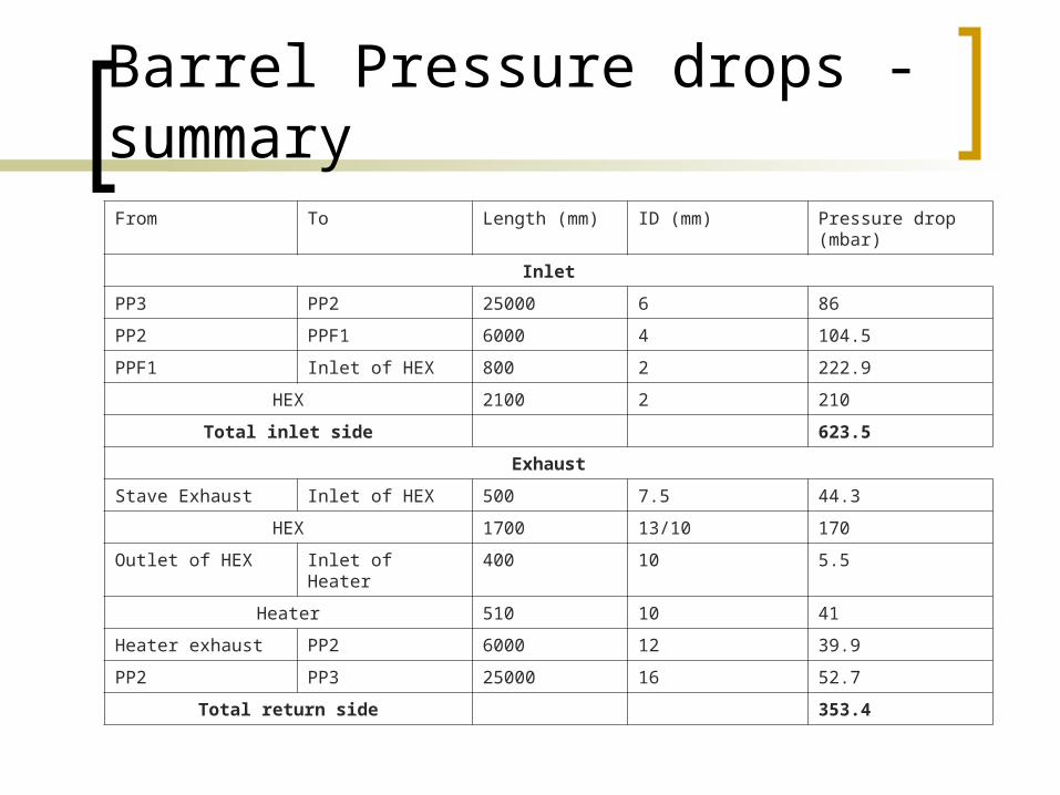
Barrel Pressure drops - summaryFrom To Length (mm) ID (mm) Pressure drop (mbar)
Inlet
PP3 PP2 25000 6 86
PP2 PPF1 6000 4 104.5
PPF1 Inlet of HEX 800 2 222.9
HEX 2100 2 210
Total inlet side 623.5
Exhaust
Stave Exhaust Inlet of HEX 500 7.5 44.3
HEX 1700 13/10 170
Outlet of HEX Inlet of Heater 400 10 5.5
Heater 510 10 41
Heater exhaust PP2 6000 12 39.9
PP2 PP3 25000 16 52.7
Total return side 353.4

13th April 2005 R.Bates, QM
Extra slides
13th April 2005 R.Bates, QM
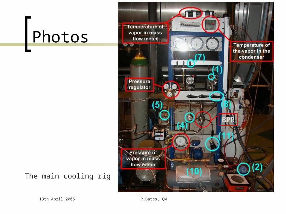
Photos
The main cooling rig
BPR

13th April 2005 R.Bates, QM
Condenser, volume meter, PLC

13th April 2005 R.Bates, QM
Power supplies for cooling loop heaters

13th April 2005 R.Bates, QM
Barrel cooling loop picturesFinal cooling loopBarrel 6 manifoldBarrel 3 pipe run manifold to HEX36 ceramic heaters
13th April 2005 R.Bates, QM
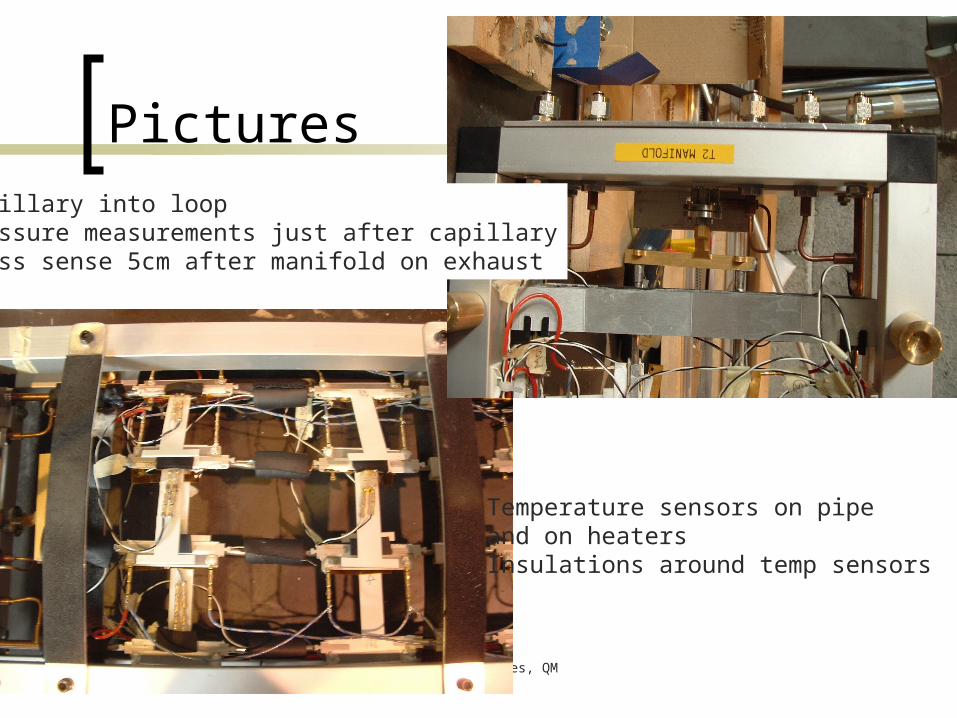
PicturesCapillary into loopPressure measurements just after capillaryPress sense 5cm after manifold on exhaust
Temperature sensors on pipeand on heatersInsulations around temp sensors
13th April 2005 R.Bates, QM
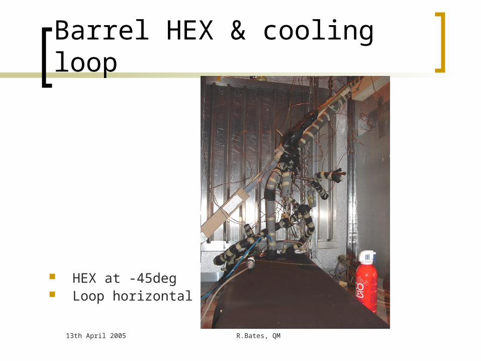
Barrel HEX & cooling loop
HEX at -45deg Loop horizontal
13th April 2005 R.Bates, QM
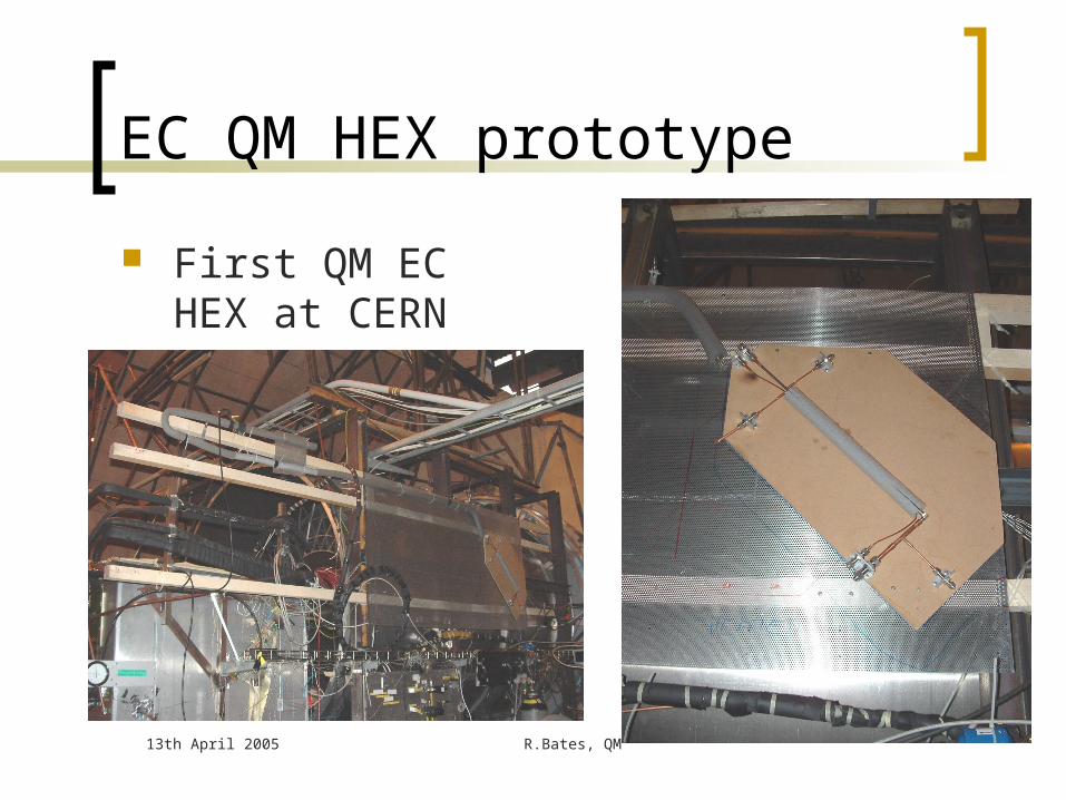
EC QM HEX prototype
First QM EC HEX at CERN

13th April 2005 R.Bates, QM
Pressure specifications High input P : MinPinlet > Psat(T=40°C) = 12.8bara MinPinlet= 13bara
Psat(T=35°C) = 11.3bara MinPinlet= 11.5bara Low evaporating pressure : P(T=-25°C) = 1.67bara Pressure drops
Liquid side Capillary to PR = 1bara PR to cooling rack = 1bara PR range (for flow regulation) = 1baraPressure from liquid pump = 16bara
Vapour side Pmin at inlet of BPR = 1.3bara Pressure drop from detector structures to BPR = 350mbara Pressure drop includes drop along Heater, (budget = 50mbar), HEX, on-
cylinder pipe work, and rest of pipe work to BPR. Higher massflow implies higher pressure drops in system
BIGGER pipes, bigger Heater etc And more powerful Heater

13th April 2005 R.Bates, QM
Number of circuits and capacity
Table 1: basic parameters and cooling capacity of the SCT evaporative circuits
Numbers of capillaries per circuit
Number of circuits
Nominal power load
Subtotal nominal power
load
[W] [kW]
SCT Barrel 2 44 504 22.2
SCT EC (3 sectors disk)
3 64 346.5 22.2
SCT EC (2 sectors disk)
2 8 241.5 1.9
TOTAL 116 46.3
13th April 2005 R.Bates, QM
Barrel +45deg, change in operating conditions of HEX as TlbHEX and power changes


![M1 Garand Barrel Replacement – New Barrel[1]](https://static.documents.pub/doc/80x56/577c79801a28abe05492e684/m1-garand-barrel-replacement-a-new-barrel1.jpg)


![TOPN Messages - Cisco · %TR-2-PANICINF: Unit [dec], PI [hex] [hex] [hex] [hex] [hex] [hex] Explanation This message is similar to the (Jeanine check source.) Recommended Action Copy](https://static.documents.pub/doc/80x56/5f96ea0c176ab92a087a6e14/topn-messages-cisco-tr-2-panicinf-unit-dec-pi-hex-hex-hex-hex-hex.jpg)


