Measuring Cheng Cycle trends at FS Karton GmbH Neuss Citation for published version (APA): Doelman, R. B. (1994). Measuring Cheng Cycle trends at FS Karton GmbH Neuss. (DCT rapporten; Vol. 1994.015). Technische Universiteit Eindhoven. Document status and date: Published: 01/01/1994 Document Version: Publisher’s PDF, also known as Version of Record (includes final page, issue and volume numbers) Please check the document version of this publication: • A submitted manuscript is the version of the article upon submission and before peer-review. There can be important differences between the submitted version and the official published version of record. People interested in the research are advised to contact the author for the final version of the publication, or visit the DOI to the publisher's website. • The final author version and the galley proof are versions of the publication after peer review. • The final published version features the final layout of the paper including the volume, issue and page numbers. Link to publication General rights Copyright and moral rights for the publications made accessible in the public portal are retained by the authors and/or other copyright owners and it is a condition of accessing publications that users recognise and abide by the legal requirements associated with these rights. • Users may download and print one copy of any publication from the public portal for the purpose of private study or research. • You may not further distribute the material or use it for any profit-making activity or commercial gain • You may freely distribute the URL identifying the publication in the public portal. If the publication is distributed under the terms of Article 25fa of the Dutch Copyright Act, indicated by the “Taverne” license above, please follow below link for the End User Agreement: www.tue.nl/taverne Take down policy If you believe that this document breaches copyright please contact us at: [email protected]providing details and we will investigate your claim. Download date: 11. Mar. 2022
Transcript
Measuring Cheng Cycle trends at FS Karton GmbH Neuss
Citation for published version (APA):Doelman, R. B. (1994). Measuring Cheng Cycle trends at FS Karton GmbH Neuss. (DCT rapporten; Vol.1994.015). Technische Universiteit Eindhoven.
Document status and date:Published: 01/01/1994
Document Version:Publisher’s PDF, also known as Version of Record (includes final page, issue and volume numbers)
Please check the document version of this publication:
• A submitted manuscript is the version of the article upon submission and before peer-review. There can beimportant differences between the submitted version and the official published version of record. Peopleinterested in the research are advised to contact the author for the final version of the publication, or visit theDOI to the publisher's website.• The final author version and the galley proof are versions of the publication after peer review.• The final published version features the final layout of the paper including the volume, issue and pagenumbers.Link to publication
General rightsCopyright and moral rights for the publications made accessible in the public portal are retained by the authors and/or other copyright ownersand it is a condition of accessing publications that users recognise and abide by the legal requirements associated with these rights.
• Users may download and print one copy of any publication from the public portal for the purpose of private study or research. • You may not further distribute the material or use it for any profit-making activity or commercial gain • You may freely distribute the URL identifying the publication in the public portal.
If the publication is distributed under the terms of Article 25fa of the Dutch Copyright Act, indicated by the “Taverne” license above, pleasefollow below link for the End User Agreement:www.tue.nl/taverne
Take down policyIf you believe that this document breaches copyright please contact us at:[email protected] details and we will investigate your claim.
MEASURING CHENG CYCLE TRENDS AT FS KARTON GmbW NEUSS
Ricky Doelman WFW Report 94.015
MEASURING CHENG CYCLE TRENDS AT FS KARTON GmbH NEUSS
CONTENTS
Introduction
Aim of the Report
1. Measurable Trendpoints
2. Graphical Representations of Signal Variables
Appendix
PAGE
1
2
3
5
Introduction
FS Karton GmbH in Neuss is a producer and seller of high quality folding boxboard for packaging purposes. The continuous boxboard production process extensively consumes steam and electricity. Steam is needed for drying purposes; electricity is needed to fullfil the power demand of the machinery. In case of a malfunction in the production process the steam demand declines, while extra electrical energy is required to restart the process.
Recently, together with a more advanced production line, a new powerhteam generating system has been brought into use. The heart of the power plant consists of an Allison 501 KH gasturbine which has been adapted in such a way that it is possible to inject steam into the combustion chamber of the gasturbine. Whenever there are situations characterised by more need for electric power and less need for steam, via an extra injection of steam, the mass flow through the expander is increased, and so a higher electricity output is created.
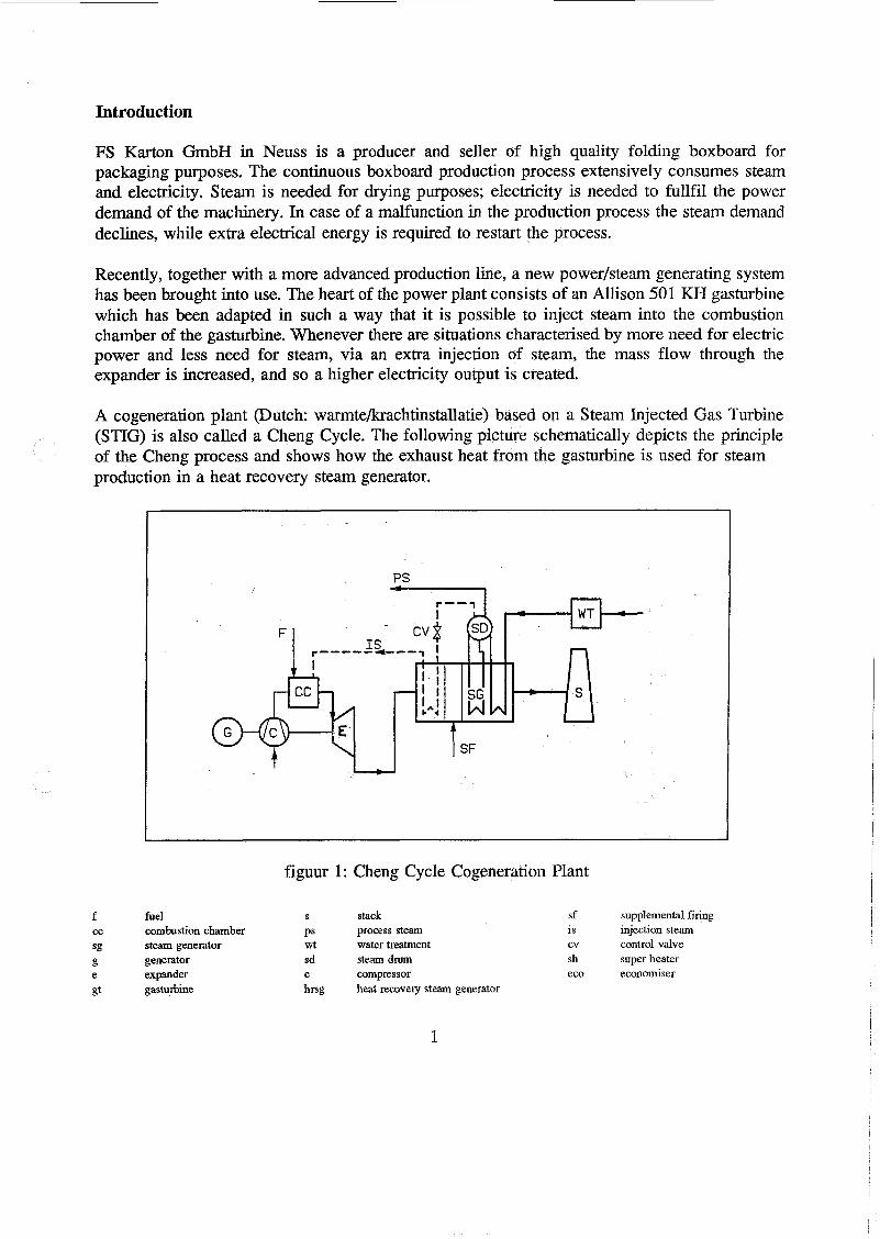
A cogeneration plant (Dutch: warmtebrachtinstallatie) based on a Steam Injected Gas Turbine (STIG) is also called a Cheng Cycle. The following picture schematically depicts the principle of the Cheng process and shows how the exhaust heat from the gasturbine is used for steam production in a heat recovery steam generator.
I
figuur 1: Cheng Cycle Cogeneration Plant
f fuel S stack sf supplemental firing cc combustion chamber PS process steam is injection steam sg steam generator wt water treatment cv control valve g generator sa steam a m sh super heater e expander c compressor eco economiser gt gasturbine hrsg heat recovery steam generator
1
process description:
first the feedwater is treated (wt), then it is preheated in the economiser (eko) from where it flows to a steam drum (sd). From there the water leads to the evaporator (sg) where steam is generated. The steam is lead back to the drum (sd) from where it can either be directed towards the process (ps), or it can be further heated in the superheater (sh) and injected into the combustion chamber of the gasturbine (cc), where it expands (e), thus producing additional work. With the supplemental firing (sf) the total steam producing capability of the system can be increased.
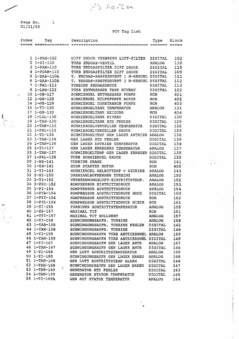
A process computer controls and supervises the Cheng Cycle and acquires data from it. Data is saved at intervals of every 60 seconds and stored in files which contain 1 hour of data. 26 files are saved for each trend point, providing for 26 hours of data. To store data for longer periods of time, the trend files are saved to an archive on floppy. FS Karton supplied us with their Trend Archive Reader and floppies which contain measurement data over 2 days.
Aim of the report:
- to indicate which trend points are available for dynamic measurement
- to convert the trend files to such a format that they are ready for use in MATLAB and/or PRIMAL and system identification can be performed
- to supply measurement data on behalf of the project on 'Steady State Modeling and Economical Optimisation' (Frans Penning)
2
1. Measurable Trendpoints
In this section we present a scheme in which we indicate which trendpoints are accessible for measurement. This scheme is a major simplification of the original Process and Instrumentation Diagram. Simplification has been performed by omitting
- drawing numbers - line diameters and specifications - normally closed valves, safety relief valves and reducers - supplier _ _ limits
Furthermore, the symbols used here are not according to DIN or ISO-standards. This slight abuse of representation should not create any misinterpretation. The following letter codes are used:
P pressure n rotational speed f flow V voltage T temperature I current 1 level P power
The letter code is followed by a number. This number equals the index number FS Karton uses to indicate a trend point, e.g. ’ 103’ means ’eko speisewasser eintrittsdruck’ (see Appendix).
figuur 2: Cheng Cycle Cogeneration Plant
3
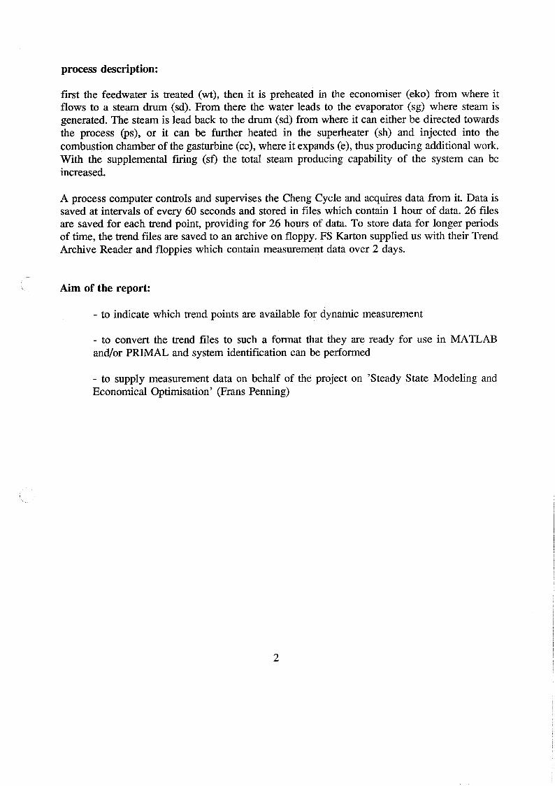
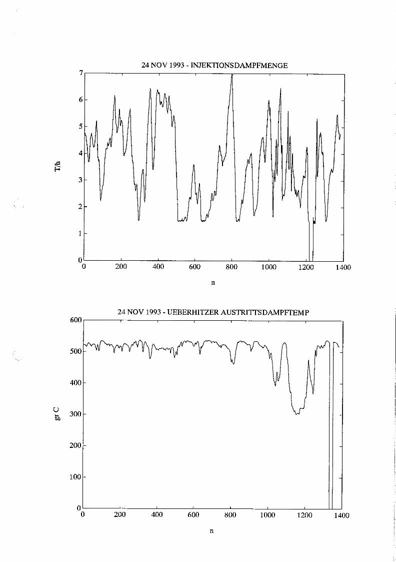
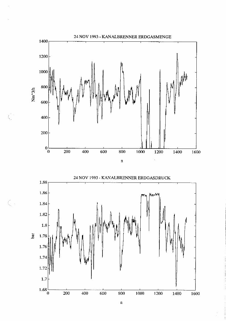
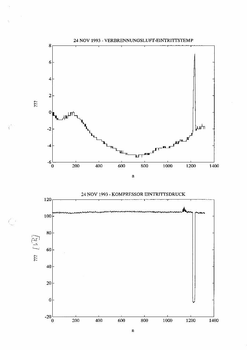
2. Graphical Representation of Signal Variables
/
Measurement data is available in digital form and in such a format that it can be processed in MATLAB or PRIMAL for system identification purposes.
On behalf of the project on 'Steady State Modeling and Economical Optimisation' (see: Report 3 - Collecting Information at FS Karton Neuss - Chapter. 5 - Frans Penning) and to allow for visual inspection of the measured data, we present in this section the signal variables as a function of time in graphical form. The signal variables are grouped together as follows:
DIFF DRUCK VERBRENN LUFT-FILTER DIGITAL TURB ERDGAS-VENTIL ANALOG TURB ERDGASFILTER DIFF DRUCK DIGITAL TURB ERDGASFILTER DIFF DRUCK DIGITAL T. ERDGAS-ABSPERRVENT 1 N-GESCHL DIGITAL T. ERDGAS-ABSPERRVENT 2 N-GESCHL DIGITAL TURBINE ERDGASDRUCK DIGITAL TURB ENTWAESSER TANK NIVEAU DIGITAL SCHMIEROEL ENTWAESSER PUMPE RCM SCHMIEROEL HILFSPUMPE MOTOR RCM SCHMIEROEL DUNSTABSCH PUMPE RCM SCHMIEROELTANK TEMPERATUR ANALOG SCHMIEROELTANK HEIZUNG RCM SCHMIEROELTANK NIVEAU DIGITAL SCHMIEROELTANK RTD FEHLER DIGITAL SCHMIEROELVERTEILER TEMPERATUR DIGITAL SCHMIEROELVERTEILER DRUCK DIGITAL SCHMIEROELTEMP GEN LAGER ANTRIEB ANALOG GEN LAGER RTD FEHLER DIGITAL GEN LAGER ANTRIEB TEMPERATUR DIGITAL GEN LAGER ERREGERS TEMPERATUR ANALOG SCHMIEROELTEMP GEN LAGER ERREGER DIGITAL TURB SCHMIEROEL DRUCK DIGITAL TURBINE CRANK RCM HYDR STARTER MOTOR RCM SCHMIEROEL ABLAUFTEMP v GETRIEB ANALOG DREHZAHLAUFNEHMER TURBINE ANALOG VERBRENNUNGSLUFT-EINTRITTSTEMP. ANALOG KOMPRESSOR EINTRITTSDRUCK ANALOG KOMPRESSOR AUSTRITTSDRUCK AììALOG KOMPRESSOR AUSTRITTSDRUCK HOCH DIGITAL KOMPRESSOR AUSTRITTSDRUCK RCM KOMPRESSOR AUSTRITTSDRUCK NIEDR RCM TURBINEN AUSTRITTSTEMPERATUR ANALOG MAXIMAL TIT RCM MAXIMAL TIT SOLLWERT ANALOG SCHWINGUNGSAUFN. TURBINE ANALOG SCHWINGUNGSAUFN. TURBINE FEHLER DIGITAL SCHWINGUNGSAUFN. TURBINE DIGITAL SCHWINGUNGSAUFN TURB ABTRIEBSWEL ANALOG SCHWINGUNGSAUFN TURB ABTRIEBSWEL DIGITAL SCHWINGUNGSAUFN GEN LAGER ANTR ANALOG SCHWINGUNGSAUFN GEN LAGER ANTR DIGITAL GEN LUFT AUSTRITTSTEMPERATUR ANALOG SCHWINGUNGSAUFN GEN LAGER ERREG ANALOG GEN LUFT AUSTRITTSTEMP ALARM DIGITAL SCHWINGUNGSAUFN GEN LAGER ERREG DIGITAL GENERATOR RTD FEHLER DIGITAL GENERATOR STATOR TEMPERATUR DIG I TAL GEN ROT STATOR TEMPERATUR ANALOG
GEN GELB STATOR TEMPERATUR ANALOG BEN BLAU STATOR TEMPERATUR ANALOG TURBINE LAEUFT/STOP RCM TURBINE ABSCHALTUNG ZUAMMENFASS TEXT- TURBINE SUMMENALARM DIGITAL TURBINE LAEUFT DIGITAL TIT SOLLWERT STATION ABSCHALTUNG RUCKSTELLUNG RCM TURBINE DIGITAL LEITSYS FEHLER DIGITAL
KOMP EINTEMP ELEMENT UNTERSCHIED DIGITAL THERMOELEMENT FEHLER DIGITAL THERMOELEMENT UNTERSCHIED DIGITAL MAXIMAL TIT DIGITAL FALSCHE FLAMME DIGITAL TURBINE OBERTEMPERATUR ANFANG DIGITAL TURBINE OBERTEMPERATUR LAEUFT DIGITAL TUBINE OBERDREHZAHLLAUFNEHMER DIGITAL TURBINENSTATUS TEXT TURBINE FERN BETRIEB DIG I TAL TURBINE SUMMENALARM DIGITAL SERIAL LINK ALARM DIGITAL SERIAL LINK STATUS ANALOG HAND NOT AUS RCM KOMPR WASCHPUMPE RCM SCHALLHAUBE LUFT-AUSTRITTSTEMP. ANALOG SCHALLHAUBE ALARM GAS-DETEKTOR DIGITAL SCHALLHAUBE LUFT-AUSTRITTSTEMP. DIGITAL SCHALLH BELUEFTUNG FILTER DeltaP DIGITAL SHALLHAUBE LUFT ALARM DIGITAL SCHALLHAUBE LUEFTERMOTOR RCM
DIGITAL SCHALLHAUBE LUFTMENGE EIN SCHALLHAUBE LUFTMENGE AUFHEBEN DIGITAL SCHALLHAUBE FEUER DIGITAL FEUERSYSTEM FEHLER DIGITAL DRUCKLUFT DRUCK ALARM DIGITAL TURBINE ZEITZAHLER ANALOG TURBINE ZEITZAHLER MODE TEXT ABBLASEBEHAELTER NIVEAU DIGITAL ABSALZUNG LEITFAEHIGXEIT STATION EK0 EINTRITT SPEISEWASSEFWENGE ANALOG EK0 SPEISEWASSER EINTRITTSDRUCK ANALOG SPEISEPUMPE A RCM SPEISEPUMPE C RCM KESSELTROMMEL DRUCK ANALOG KESSEL DAMPFMENGE ANALOG KESSELTROMMEL NIVEAU STATION KESSELTROMMEL NIVEAU HOCH RCM KESSELTROMMEL DRUCK RCM KESSELTROMMEL NIVEAU NIEDERICH A RCM
KESSELTROMMEL NIVEAU NIEDERICH B RCM ANFAHRUMWAELZPUMPE RCM KESSEL UMWAELZMENGE RCM PROZESSDAMPF MENGE ANALO-G PROZESSDAMPF DRUCK STAT I ON INJEKTIONSDAMPF ABSPERRVENTIL DD INJEKT IONSDMPF EIENGE STATION 1NJ.DAMPF-ABSCHEIDER KONDENSATAB DIGITAL KESSELTROMMEL NIVEAU (LT) RCM KESSELTROMMEL DRUCX (PT) RCM INJEKTIONDAMPF ENTW VENTILE DD UEBERHITZER AUSTRITTS-DAMPFTEMP. ANALOG UEBERH. ENTW.VENTIL POS. OFFEN RCM UEBERH. ENTW.VENTIL POS. OFFEN RCM 1NJ.D.LEITG ENTW.VENTIL POS. OFF RCM 1NJ.D.LEITG ENTW.VENTIL POS. OFF RCM REGELVENTIL KONTROL BAMPFINJ STAT I ON KANALBRENNER ERDGASMENGE ANALOG KANALBRENNER RUCKSTELLUNG RCM
ANALOG KANALBRENNER ERDGAS DRUCK KANALBRENNER ERDGASTEMPERATUR ANALOG KANALBRENNER IN BETRIEB DIGITAL KANALBRENNER/KESSELTROMMeL LEIT STATION KANALBRENNER ERDGAS DRUCK ALARM DIGITAL KANALBR. TURBINEN STARTFREIGABE DIGITAL KANALBR. FLAMMENWAECHTER DIGITAL KANALBR. FLAMMENWAECHTER DIGITAL KANALBRENNER REGELUNG DD
DIGITAL KANALBRENNER GASDRUCK KANALBR SCANNER-VENT RCM KANALBR SCANNERGEBL AUSTR DRUCK DIGITAL KANALBR INSTRUMENTEN-LUFTDRUCK DIGITAL KANALBR ZUSATZLUFT REGELKLAPPE STATION KANALBRENNER ZUSATZLUFT GEBL RCM KANALBR ZUSATZLUFTDRUCK GEBL DRK DIGITAL KANALBR ZUENDBR GASABSPERRVENTIL DIGITAL TURBINE ABGASKANALDRUCK DIGITAL FEUERUNGSTEMPERATUR im KANAL DIGITAL KANALBR. BELUEFTUNG VORANG DIG I TAL KANALBR. BELUEFTUNG FERTIG DIGITAL KANALBR ALLGEM KOND ANWESEND DIGITAL ABGASTEMP VERDAMPFER EINTRITT ANALOG ABGASTEMP EK0 AUSTRITT ANALOG KANALBRENNER ABSCHALTUNG RCM FS-KARTON STROMVERBRAUCH APSBLOG GENERATOR LEISTUNG STATION GENERATOR BLINDLEISTUNG ANALOG GENERATORSPANNUNG ANALOG GENERATORSTROM ANALOG GENERATOR COS PHI ANALOG
DIGITAL GENERATORSCHALTER GENERATOR SPANNUNGNIEDERICH DIGITAL GENERATOR STROMRUECXSEITE DIGITAL GENERATOR EXCITATION FEHLER DIGIT-AL GENERATUR STROMHOCH DIGITAL GENERATOR SPANNUNGHOCH DIGITAL GENERATOR ERD FEHLER BPGPTBE GENERATOR DIFFEREZSTROM DIGITAL GENERATOR FREQUENZNIEDERICH DIGITAL
DIGITAL GENERATOR FREQUENZHOCH INSEL/PARALLEL BETRIEB DIGITAL GENERATOR LEISTUNGBEREIT RCM LEISTUNG VOM NET2 ANALOG MCC MOTOR STARTER NICHT IN POS DIGITAL ROTOR DIODE / EXCITATION ALARM DIGITAL AUTO SYNCHRONOZIEREN FEHLER DIGITAL GEN SCHALTER OFFEN NICHT DIGITAL STATUS MCC ANSPEISUNG DIGITAL
DIGITAL MCC FEHLER - 220 VAC MCC MOTOR STARTER NICHT IN POS DIGITAL MCB OFFEN DIGITAL TURBINE ERDGASMENGE ANALOG TURBINE ERDGAS VERSORGUNGSDRUCX ANALOG
ANALOG TURBINE ERDGASTEMPERATUR DAMPFBEDARFSABDECKUNG RCM STROMBEDARFSABDECKUNG RCM MAXIMALE STROMSERZEUGUNG RCM
N90STA MFPO1 LIM/BIM N90STA DIFF DRUCK VERBRENN LUFT-FILTER DIGITAL TURB ERDGAS-VENTIL ANALOG
DIGITAL TURB ERDGASFILTER DIFF DRUCK TURB ERDGASFILTER DIFF DRUCK DIGITAL T. ERDGAS-ABSPERRVENT 1 N-GESCHL DIGITAL T. ERDGAS-ABSPERRVENT 2 N-GESCHL DIGITAL TURBINE ERDGASDRUCK DIGITAL
DIGITAL TURB ENTWAESSER TANK NIVEAU SCHMIEROEL ENTWAESSER PUMPE RCM SCHMIEROEL HILFSPUMPE MOTOR RCM SCHMIEROEL DUNSTABSCH PUMPE RCM SCHMIEROELTANK TEMPERATUR ANALOG SCHMIEROELTANK HEIZUNG RCM
DIGITAL SCHMIEROELTANK NIVEAU DIGITAL SCHMIEROELTANK RTD FEHLER
SCHMIEROELVERTEILER TEMPERATUR DIGITAL DIGITAL SCHMIEROELVERTEILER DRUCK
SCHMIEROELTEMP GEN LAGER ANTRPEB ANALOG DIGITAL GEN LAGER RTD FEHLER
GEN LAGER ANTRIEB TEMPERATUR DIG I TAL GEN LAGER ERREGERS TEMPERATUR ANALOG