61
Measuring instruments (ST-03)

Measuring instruments
(ST-03)

Types of measuring instruments
Analog Instruments Digital Instruments
An analog instrument gives an output that varies continuously as the quantity being measured changes.
A digital instrument has an output that varies in discrete steps
The output can have an infinite number of values within the range
This instrument has only finite values within the range.

Voltmeter
• It measures the voltage difference (AC/DC) between two points in a circuit.
• An analog voltmeter moves a pointer across a scale in proportion to the circuit’s voltage.
• A digital voltmeter provides a numerical display.
• Voltmeter is always connected in parallel with load across which voltage is to be measured.

Voltmeter (contd…)
• The internal resistance (series resistance) of a voltmeter is very high in order to minimize the loading effect.
• When the internal resistance of a voltmeter is not much high compared to the resistance of the circuit across which it is connected, the measured voltage becomes low. This is called the loading effect of voltmeter.
• The internal resistance of an ideal voltmeter is infinity.

How to measure voltage with voltmeter ?
• Connect one node of Voltmeter at V and another node at C terminal.
• Always select proper range before using meter.
• While measuring high voltage, ensure that lead may not be exposed at anywhere.

Ammeter/Ampere meter
• It measures the current (AC/DC).
• Always connected in series in the circuit.
• Internal Resistance (Shunt resistance) is very low so that most of the current passes through it.
• Internal resistance of an ideal ammeter is zero.

Symbols
Symbols of AC & DC in multimeter
Voltmeter symbol
Ammetersymbol

Ohmmeter
• Used for measuring resistance.
• Connected in parallel.
• Connect one node at Ωand another node at C terminal.

Multimeter common symbols

Outdoor(Field) Measuring Instruments
• Megger
• Earth Tester
• Transmission measuring Set(TMS)
• Cross talk meter
• Cable Route Tracer
• Cable fault Locator

Types of Cable faults in underground cables
• Earth Fault
1. When any of the conductors of the cable comes in contact with the earth.
2. This type of fault allows the current carried by the conductor to leak to the earth directly or indirectly instead of going to the apparatus to whichthe conductor is connected.

Short circuit fault
• When two or more conductors of a cable come in contact with each other,then this is called a short circuit fault.
• A short-circuit fault occurs when theindividual insulation of the conductor core is damaged.

Open circuit fault
• When one or more cable conductors break,it leads to discontinuity. This discontinuity alsooccurs when the cable comes out of its jointdue to mechanical stress.

Low insulation fault
• When the cable core insulation material is deteriorated by ageing, moisture, excessive heating or dirt the insulation resistance is dropped to very low value it is called as low insulation fault.

Megger( analog & Digital)

Megger
• a portable instrument used to measure insulation resistance of underground cables.
• It is basically an Ohmmeter to measure high resistance(in MΩ).
• Insulation resistance of cable is measured by Megger.
• Usually 500 V megger is used for testing insulation resistance of Signalling cables whereas 100V megger is used for Telecom cables.

How to measure insulation resistance?
• Two types of Insulation resistances are measured.
1. between two conductors (line to line)(L-L)

Line to Earth (L-E) insulation test

Meggering (contd ...)
• Both the ends of the conductors must be disconnected (isolated) from the circuit before carrying out the test.
• In case of analog megger, generator handle is steadily rotated at a uniform speed till the pointer gives a steady reading.
• After completing meggering ,each conductor must be earthed before running circuit on it.
• Megger should be kept on plane surface to avoid any error.
• Insulation resistance more than 10 MΩ for a particular pair is considered GOOD.
• Insulation resistance less than 2 MΩ for a particular pair is considered FAULTY

CONDUCTION TEST /LOOP RESISTANCE TEST
• to measure the Ohmic resistance value of the conductor

LOOP RESISTANCE TEST
• Ohm meter (Digital multi meter) is used to carry out the test.
• The transmission line must be disconnected from the circuit before carrying out the test
• Connect the two limbs L1 & L2 of the pair to the connecting leads of the Multi meter at the near end
• both the limbs must be looped at the far end as shown in the diagram

EARTH RESISTANCE TESTER
• It is an Ohmmeter to measure earth resistance.
• e1 is called potential spike.
• e2 is called auxiliary earth.
• Distance between two spikesis 20m.
• The e1 and e2 are placed intothe soil to a depth of 14 cm.
• All the three electrodes must be in the same line.
• Earth resistance should be less than 1Ω.

Transmission Measuring Set (TMS)
• The meter is basically divided into two sections. One is the oscillator section and the other is the level meter section.
• The oscillator section consists of frequency selector switch.
• The power level of the oscillator is selected as per the requirement with the help of power selector switch.
• The power level of the test tone selected is 0dBm.

Some Important terms• Insertion Loss : When the transmission path is loaded by the devices ,
some power is taken away (consumed) by the devices .This loss is called insertion loss . The signal level is measured by without load and with load. The difference is the Insertion Loss .
• Return Loss: When signal is sent to the device under test (through transmission line ) the characteristics impedance of the line does not match exactly with the impedance of the meter . Some portion of the transmitted power returns back to the source due to the mismatch . The returned power is considered as Return loss . This loss is measured by the level meter .

Impedance button
Loss of range selection
Potentiometer knob
Impedance button
Output tone
Input tone
Frequency selection
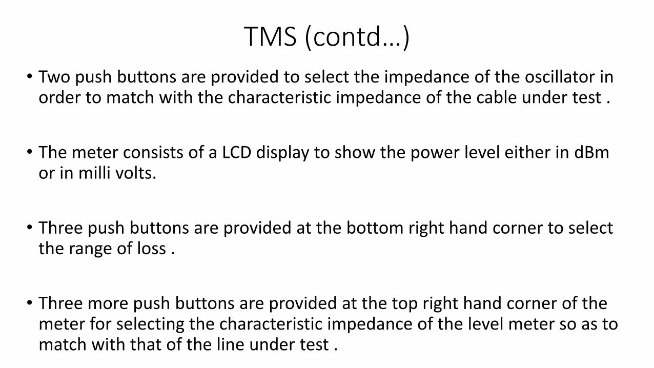
TMS (contd…)• Two push buttons are provided to select the impedance of the oscillator in
order to match with the characteristic impedance of the cable under test .
• The meter consists of a LCD display to show the power level either in dBmor in milli volts.
• Three push buttons are provided at the bottom right hand corner to select the range of loss .
• Three more push buttons are provided at the top right hand corner of the meter for selecting the characteristic impedance of the level meter so as to match with that of the line under test .

Procedure for calibration of TMSBefore carrying out the test ensure that the output impedance of the meter, Characteristic impedance of the line and the input impedance of the meter are same for the transfer of maximum power and to have proper reading
1. Select the frequency
2. Select the power level
3. Set the same O/P and I/P impedance as per the line’s Characteristic impedance
4. Take the patch cord supplied along with the kit and loop it between the O/P and I/P sockets of the meter located

TMS( Contd..)• The far end of the tx line is to be connected to the i/p socket of the meter
located at far end.
• The LCD displays the power level at the far end
• The loss is found out by subtracting the reading of level meter at the far end from the selected power level at the near end i.e. 0dBm. The loss will be measured in dB.

TMS(contd..)
• Measurement of transmission loss using single TMS (4-wire loop)
• For 0.9mm quad cable,
transmission loss is
0.63dB/km at 800Hz
&
1.2 dB/km at 2KHz. Station A Station B
O/P
I/P

Crosstalk Meter

CROSSTALK
• Crosstalk (XT) is a phenomenon by which a signal transmitted on one circuit of a transmission system creates an undesired effect in another circuit.
• Cross talk is the leakage of any signal.
• The signal of one pair of the cable induces unwanted signals in adjacent pairs due to electrostatic and electromagnetic induction effects. The first pair is called the DISTURBING PAIR and the other pair is called the DISTURBED PAIR.
• Types of cross talk-Near end cross talk (NEXT),Far end cross talk(FEXT)
• Crosstalk is measured in audio frequency range.

Measurement of Near End Cross Talk (NEXT)
• The cross talk which is measured at the end from where the signal is fed is called the Near End Cross Talk.
• One Cross Talk measuring Set is required to carry out the test

NEXT(Contd…)
• Set the impedance switches corresponding to the cable under test.
• Select the test frequency to 1000 Hz by pressing the test frequency push button.
• Adjust the level to 0 dBm with set level pot.
• Now the instrument is ready to measure cross talk.
• Connect the instrument to the Tx line as per the connection diagram and record the readings.
• Standard Value of NEXT is better than -61dB.

Measurement of Far End Cross Talk (FEXT)• The cross talk that is measured at other end of the line from where the
signal is fed is called as Far end cross talk.
• Two Cross Talk Measuring Sets are required to carry out this test.
• One meter at the near end and another at the Far end is required.
• Standard value of FEXT is better than -65dB

FEXT(contd…)
• The first instrument is connected to the disturbing pair at the near end to transmit the test signal and the other end of the pair is terminated by its characteristic impedance.
• The second meter is connected to the disturbed pair at the far end and the near end is terminated with characteristic impedance as shown in the below diagram.

Cable Fault Locator
• Also called Time Domain Reflectometer(TDR)
• Locates faults in the telecom cables
• Types of faults are
1. SHORT Circuit faults
2. OPEN Circuit faults(cable break)
3. LOW Insulation faults

Working of Cable fault locator
• A Time Domain Reflectometer (TDR) sends a short duration pulse into the cable.
• This pulse reflects back from the point of change in impedance in the cable.
• A TDR measures the time taken by the pulse to reflect back from the point of change in impedance (or the point of fault).
• The TDR uses Velocity of propagation (VOP) to calculate cable length.
• Velocity of propagation is a cable specification indicating the speed at which a signal travels down the cable. VOP of 66 means the signal travels at 66% of the speed of light.

Cable Fault locator(Contd…)• Different cables have different VOP settings
V= Velocity of propagation (VOP)
T=the time taken by the signal to travel and reflect back from the
point of fault
L= distance of fault
2L = VT
L = VT/2
Thus, if VOP and total time of to and fro travel of pulse transmission is known, the distance to the fault can be found.

Cable Fault locator(Contd…)• The reflections are traced on a graphical
display with amplitude on y-axis and the total time on x-axis. The elapsed time is directly related to the
distance to the fault location.
2. If the injected signal encounters an open circuit (high impedance), it results in high amplitude upward deflection on the trace.
3. While in case of a short-circuit fault or low insulation fault, the trace will show
a high amplitude negative deflection.
Advantages & disadvantages of TDR
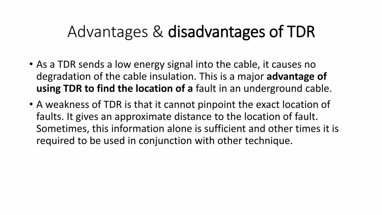
• As a TDR sends a low energy signal into the cable, it causes no degradation of the cable insulation. This is a major advantage of using TDR to find the location of a fault in an underground cable.
• A weakness of TDR is that it cannot pinpoint the exact location of faults. It gives an approximate distance to the location of fault. Sometimes, this information alone is sufficient and other times it is required to be used in conjunction with other technique.

Cable route tracer(Cable Route locator)• Helpful in tracing the path of underground cable
• measurement of the depth of underground cable
• It consists of two units:
1. Transmitter or Signal Generator
2. Receiver or Cable Avoidance Tool
Generator
Cable Avoidance
tool
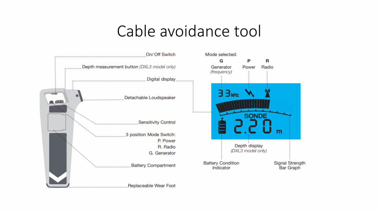
Cable avoidance tool

OFC Splicing Machine

Fusion Splicing Machine
• It melts the two ends of fibre optic cables together to form a continuous cable.
• To do this properly, machine must align the cable, touch the ends together, and send heat or an electric arc through the joint to melt the glass.
• This process requires a great deal of precision and accuracy.
• Permissible loss of Fusion splice should be less than 0.1dB

Arc zone
Oven

Optical Time Domain Reflectometer(OTDR)

Advantages of OTDR• OTDR can measure the following parameters.
1. Measures the cable brakes with almost exact distance.
2. Measures the splice and connector loss
3. Measures the transmission loss
4. Gives the length of the cable.

Typical OTDR trace

Visual Fault Locators (VFL)
• Visual Fault Locators are red light lasers.
• They visually locate faults, up to around 5 kilometres.
• By sending visual light, the operator can easily see breaks and important bends in the fibre; as the light escapes out. This function makes them useful for continuity testing of patch cords, jumpers, or short sections of fibre.

Optical power meter (OPM)
• It is a hand held instruments used to measure the power of the light fed from Optical Light Source.
• Its output shows the amount of loss incurred in OFC where light was given.

Light Emitting diodes ( LEDs)
• It is an optical source that converts electrical energy into optical energy.
• A light-emitting diode (LED) is a two terminal semiconductor source that emits light when current flows through it.
• It works on spontaneous emission.
•

LASER source
• LASER is an optical source.
• LASER stands for Light Amplification by stimulated emission of radiation.
• LASER emits monochromatic light .
• works on the principle of stimulated emission.

Optical Detectors
PIN Diode
• It is a photo diode with intrinsic (un-doped) region between n & p doped regions.
Avalanche Photo Diode(APD)
• It is a semiconductor based photodiode.
• It is operated with relatively high reverse voltage

• Fibre Strippers -It is used for cutting and removing the primary coating of the opticalfibres during splicing the optical fibre cable.
• Cleaver-It is used to cut the fiber axis at 90 degree .

Crimping Tool & FDMS
• Crimping Tool – used for making RJ45 and RJ 11 connectors.
• FDMS- Fiber Distribution Management System
• FDMS provides management of large volume of Optical fibres.
It can be mounted on the wall inside the building / customer premises.

Hand Tools• HAMMER : Hammers are used for hammering
any metals or nails.
• Chisel are used for cutting and chipping away pieces of metal. Chisel are made of carbon steel.
• Wrench or Spanner- It is used to driving Nuts and Bolts. It is also used to tightening
and loosing .
• Screw Driver- It is used to driving screws in and out. It is made of high carbon steel.

Soldering iron and soldering techniques• SOLDERING IRON - It is used for joining two wires.
It is classified by working voltage and wattage
• SOLDER :- It is an alloy of different metals like lead, tin,
• Flux-To removed oxidized layer, any oil, grease etc,flux is used to clean the surface of metal.

Soldering Process• Metal pieces are first clean with help of sand papers or knives and then
heated at the place to be joint by the soldering iron.
• When the place is sufficiently heated , a little flux is to be applied so that the moisture or any oil; and greese, this is being removed by chemical action.
• A little solder is applied on the point, which melts away and flows through the entire heated surface of the material.
• Now the soldering iron or the heat is removed from the jointing place and the joint is allowed to cool-down which will make a strong permanent joint.

Vacuum Blowers And Cleaners
• It is used to clean dust particles by blowing or suctioning method from different electronic equipment and tools.
• It has two different methods of operations-
• It can be use as a blower where the dust particle are required to remove from the surface of the equipment.
• It can be used as a suction where the dust particle is required to taken off outside from the covered equipment.

Do’s
• Calibrate all the instruments once in a year.
• Check all the measuring probe Once in a year.
• Keep always higher range and then measure in any active meter.
• All the hand tools are to be lubricated once in a month.
• During use of hand tools & high voltage measurement, gloves should be used.
• Meter should be handled with care.
• At the time of high voltage measurement rubber mat should be used in floor.
• To measure any electrical quantity the polarity of meter should be connected properly.
• Do not hold the chisel by hand; it should be gripped with proper instrument.
• Do not hammer on the top of the screwdriver.
• Do not keep any hand tool the contact of open air to avoid the corrosion.
• Do not switch on the vacuum cleaner for a long time to safe electrical motor.
• At the time taking any reading in multimeter, the range selective switch should not be kept at lower range.
• In any meter, low battery should not be used.
• Do not use ammeter without shunt resistance.
Don’ts


