Measuring refractive index and thickness of thin films:a new technique
Tie-Nan Ding and Elsa Garmire
Properties of a leaky quasi-waveguide formed by a thin film of refractive index smaller than the substrateare described. By exciting these leaky waves through the substrate, we have demonstrated a convenient andaccurate method of measuring both the refractive index and thickness of thin films. Experimental resultsare given for polystyrene, with a demonstrated accuracy comparable with both that of prism coupling intoa waveguiding film and with ellipsometry.
1. Introduction
One of the early integrated optics techniques was theuse of a prism input-output coupler to determine thinfilm parameters by measurment of the so-called m-lines1 2 and their coupling angles. In recent years fur-ther studies have improved this method to providemeasurements of parameters such as dispersion.34
Prism coupling into waveguides to measure m-linecoupling angles has the advantage of convenience andaccuracy over more conventional techniques for mea-suring thin film parameters. In addition to wave-guiding dielectric films, which require the refractiveindex of the film to be higher than that of the substrate,the m-line method has also been applied to films whoserefractive index is smaller than the substrate.5 -7 Weshall call these films quasi-waveguides, since the lightis guided by the film-air interface while the reflectionat the film-substrate boundary is leaky We shall showthat by coupling into the modes of quasi-waveguidesthrough the substrate, it is possible to measure the re-fractive index and thickness of such films in exactanalogy to the prism coupling technique. By excitationfrom the substrate, the pressure, perturbation, and in-convenience of a coupling prism are avoided.
The authors are with University of Southern California, Center forLaser Studies, Los Angeles, California 90089-1112.
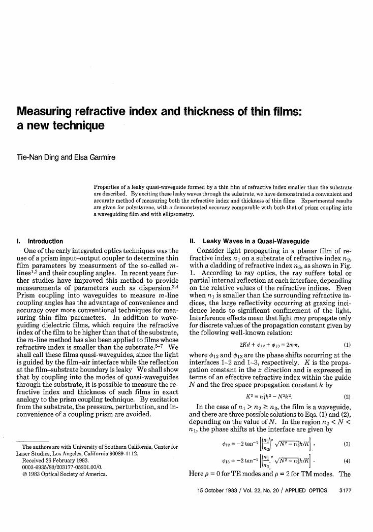
Consider light propagating in a planar film of re-fractive index nj on a substrate of refractive index n2,with a cladding of refractive index n3 , as shown in Fig.1. According to ray optics, the ray suffers total orpartial internal reflection at each interface, dependingon the relative values of the refractive indices. Evenwhen ni is smaller than the surrounding refractive in-dices, the large reflectivity occurring at grazing inci-dence leads to significant confinement of the light.Interference effects mean that light may propagate onlyfor discrete values of the propagation constant given bythe following well-known relation:
2Kd + 012 + 013 = 2mr, (1)
where 012 and 013 are the phase shifts occurring at theinterfaces 1-2 and 1-3, respectively. K is the propa-gation constant in the x direction and is expressed interms of an effective refractive index within the guideN and the free space propagation constant k by
K2 = n k2 - N2k2 (2)
In the case of n > n2 n3 , the film is a waveguide,and there are three possible solutions to Eqs. (1) and (2),depending on the value of N. In the region n 2 < N <n1 , the phase shifts at the interface are given by
result is a series of discrete guided modes. The modeswhich occur when n3 < N < n 2 are solved by noting that.b12 = 0 and 013 has the same value as in Eq. (4). Thisleads to a series of discrete modes called leaky waves inthe substrate radiation mode regime. Finally, if N <n3, then 012 and 013 both = 0, and we obtain a series ofdiscrete modes which lead to leaky waves in the claddingradiation mode regime. These modes leak both into thesubstrate and into the air. When the refractive indexof the film is smaller than that of the substrate and thecladding, n, < n3 < n2 , the film is a hollow waveguide.There is only one set of solutions to Eqs. (1) and (2)since 012 = 023 = -7r under this condition. This is aseries of discrete leaky modes in the radiation regimeof both the substrate and the cladding. Both wave-guides and hollow waveguides have been reported inmany papers.8 -10
In this paper we consider the case n2 > n, > n3 , whichwe call a quasi-waveguide. In this case, there are noguided modes, but there are three kinds of radiationmode. In the regime n3 < N < n, the phase shiftsare
012 = -ir, 13 = -2 tan- [(1:)p \N 2-nik/KI (5)
which leads to a discrete set of leaky waves in the sub-strate mode regime. When N < n3 , the phase shifts are012 =-Ad w,13 = 0, which corresponds to a series of leakywaves in the cladding radiation mode regime. Whenn, < N < n2 , there are evanescent waves in both thecladding and film, corresponding to total internal re-flection at the substrate-film interface.
The leaky modes of the quasi-waveguides are waveswhose propagation constants have a series of discretevalues in the substrate radiation mode regime, and theycarry information about the film parameters, in analogyto the set of guided modes in a true waveguide. Filmsof SiO 2 on silicon represent an important case ofquasi-waveguides, whose m-lines have been studied byprism coupling. 7 11 However, since the leaky modes ofthe quasi-waveguide leak out of the film into the sub-strate without a coupler, they can be easily observed,providing a useful technique for determining thin filmparameters directly. If this technique is to be useful,the reflectivity at the interface must be sufficiently highthat the leaky modes are strong enough to be observed.In principle, when the grazing angle is near zero, theinternal reflectivity will be near one. Thus if thethickness of the film is large enough, the mode anglesdefined by Eqs. (1) and (2) may be small enough thatobservable leaky modes will be produced.
n Fig. 1. Zigzag path of a ray in a three-layer dielectric slab structure."2 The substrate n2 is shown with a larger refractive index than the
quasi-waveguiding layer n1. Light is shown totally internally re-flected at the cladding boundary.
n3
The quasi-waveguide has an advantage over a hollowwaveguide, since the leak occurs only at one boundaryrather than at both boundaries, making the leaky modesstronger for the same film thickness. The quasi-waveguide also has an advantage over the real wave-guide because the propagation constant in the film is notaltered by the presence of a separate coupling prism. Inprinciple, leaky modes in the substrate mode regime ofa real waveguide may also be used to measure parame-ters, but these modes may tend to be swamped by thelossless guided modes. Thus the quasi-waveguide is thebest structure to investigate leaky modes for the mea-surement of film parameters. Because of their losses,leaky waves can be transmitted only for a short distanceafter they are produced. The m-line method for in-vestigating leaky modes is suitable, however, since a100-um propagation distance is long enough to producem-lines.
111. Experiment
To investigate leaky modes in the substrate regime,the substrate is in the shape of a prism. The refractiveindex of the prism should be as high as possible to de-crease the loss of the leaky modes. We use a dense flintglass (SF-10) prism with refractive index n2 = 1.72308at 0.63-ym wavelength and with an angle between theincident face and the substrate face of 60.12°. Theprism is coated with a film of polystyrene to form thequasi-waveguide. The polymer film is deposited bycoating with a solution of 645-mg polystyrene in 30-mlxylene. The quality of the film was found to depend onthe speed of the drying process-the slower the better.Drying is slowed by providing a xylene atmosphere withtwo days required to dry a high quality film.
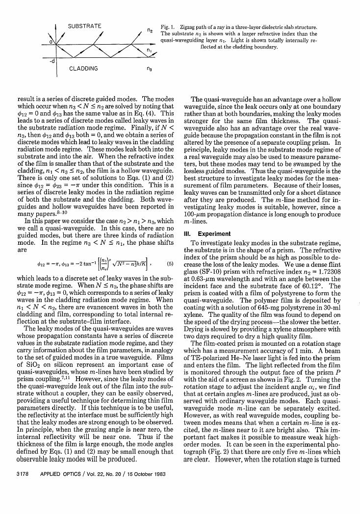
The film-coated prism is mounted on a rotation stagewhich has a measurement accuracy of 1 min. A beamof TE-polarized He-Ne laser light is fed into the prismand enters the film. The light reflected from the filmis monitored through the output face of the prism Pwith the aid of a screen as shown in Fig. 2. Turning therotation stage to adjust the incident angle ai, we findthat at certain angles m-lines are produced, just as ob-served with ordinary waveguide modes. Each quasi-waveguide mode m-line can be separately excited.However, as with real waveguide modes, coupling be-tween modes means that when a certain m-line is ex-cited, the m-lines near to it are bright also. This im-portant fact makes it possible to measure weak high-order modes. It can be seen in the experimental pho-tograph (Fig. 2) that there are only five m-lines whichare clear. However, when the rotation stage is turned
Fig. 2. Experimental setup and photograph of quasi-waveguide m-lines.
to the position of the sixth m-line, the lower order m-lines are bright, since there is coupling between themodes. Employing this phenomenon we have mea-sured the sixth m-line. The experimental results forthe measured angles are shown in Table I.
IV. Analysis
The analysis of leaky modes is exactly analogous tothat of guided modes2 and is determined by solving Eqs.(1) and (3). From any two values of the effective indexfor two modes, an equation may be derived which isindependent of the thickness of the film and dependsonly on its refractive index. Measurement of couplingangles for two modes is thus sufficient to determine therefractive index of the film. The film thickness is thencalculated from one effective index and the refractiveindex of the film. When more than two modes arepresent, a self-consistent check can be made to refinefurther the results.
From the input coupling angle, the effective index ofthe film is calculated. If the prism angle is 0 and itsrefractive index is np, the effective refractive indices Niare given in terms of the input coupling angles 'i by Ni
np sin(O + yi), where np sinyi = sinai.In the case of the quasi-waveguide, the refractive
index of the film n1 is given in terms of measured ef-fective refractive indices Ni and Nj for modes mi andmj, respectively, byVn~~~~~~~~-N2~ ~ , ,1N_____(mi + /2)7r + tan- e
,- 1Nj (mj + 1/2) r + tan-l e ~~~(6)
Thus nj is given by this transcendental equation, whichin general requires a minicomputer because of itscomplexity. However, excellent results can be obtainedby noting n' -N? << N? - n3 and using the expansiontanlz = 7r/2 - 1/z.
This leads to a simplified form of the equation:
(7)
A (Mi + )7 - mnf~ N
n1 -(mJ+l)7r-m
To lowest order the solution is obtained by ignoring thesquare roots on the right-hand side of the equation,which gives the simple expression
(mi + 1)2
(mj + 1)2 - (mi + 1)2 (N2 - NJ2). (8)
We have derived the next-order expression in the per-turbation expansion and found that this lowest-orderexpression is good to a part in 106 for all modes (at leastthrough m = 6). This is because the next-order termsin the expansion exactly cancel. Thus a computer is notrequired to find the refractive index of the film in aquasi-waveguide.
Once the refractive index has been computed, thethickness of the film is determined by
d , [(2m + 1)r + 2 tan-1 N + 1 . (9)
Again there is a simple form for this equation, whichgives the film thickness in terms of the measured ef-fective indices of the two modes without first computingthe refractive index of the film. This equation is de-rived by expanding tan-' to first order and putting thezero-order expression for the argument in the expansionto determine the first-order correction. This gives
This equation is valid to 10-4 in giving the film thick-ness.
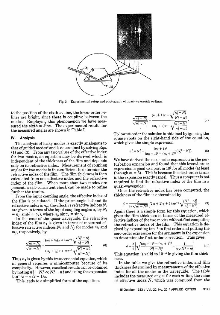
In the table we give the refractive index and filmthickness determined by measurements of the effectiveindex for all the modes in the waveguide. The tableincludes the measured angles for each m-line, the valueof effective index N, which was computed from the
Final n, and d valuesn = 1.58512 + 0.00004 Root mean square error ofd = 6.44047 + 0.03625 ptm N = 0.000177
coupling angles, final values for n, and d determined byan error minimization procedure described below, anda list of the theoretical effective indices calculated fromthese final values for refractive index and thickness.From the difference between the effective indices cal-culated from experimental results and the theoreticalcalculations for the effective index, the rms error for anyone measurement is computed to be 0.000177.
V. Discussion
To investigate the limits of experimental accuracy,we analyzed our data using computer solutions to Eq.(7). Since there are several modes, it is possible tocompare the results from each of these modes to im-prove the accuracy of n and d. Following the procedureof Ulrich and Torge2 we minimize the sum of thesquares of the error:
Mu(n,d) = [i - Ni (n,d)12 , (11)
where Ni is the effective refractive index determinedfrom measurements and Ni is the calculated effectiveindex, assuming a refractive index n and thickness d.First, we use each two of the measured propagationconstants to calculate the thickness and index of thefilm for each pair of experimental results. Then we usethe mean value of this thickness and index as an initialvalue to find the minimum point for (nd). Thisminimum is determined by calculating a at n,d and atfour nearby points, n i n and d At 6d. If any of thesevalues of a are smaller than the initial value, these newvalues for n,d become the initial point. The procedureis iterated until the minimum for a is obtained. Thevalue obtained in this fashion differed from that ob-tained by a simple average of the results of Eqs. (8) and(10) by 1 part in 105 in the refractive index and 1.5 partsin 103 in the film thickness.
The root mean square error in the measurement ofthe propagation constant is 1.8 X 10⁻⁴. The rms errorof the index of the film is 4.1 X 10⁻⁵, and the rms errorof the film thickness is 3.6 X 10⁻². Ulrich and Torgemeasured the parameters of an evaporated A1203 filmon a quartz substrate by the guided mode m-linesmethod. In their result, the rms error of the propaga-tion constants was 2 X 10⁻⁴, the index was 16 X 10-5,
and the thickness was 2 X 10⁻². Thus the two methodshave the same accuracy of measurement.12 However,the quasi-waveguide m-line method has special ad-vantages. First, the film refractive-index region whichcan be measured by this method is different from thewaveguide m-line method; the quasi-waveguide methodcan be used for low-index material. In fact, the lowerthe index of the film compared with that of the prism,the bigger the reflectivity at the interface, hence theeasier it can be measured.
The second advantage of this method is the fact thatit uses a direct measurement. In the waveguide m-linemethod, the influence of prism coupling causes a shiftof the modes due to the presence of prism. Ulrich hasanalyzed this influence and pointed out that the weakcoupling condition is very important for accuratemeasurements while ensuring that the weak couplingcondition2 is a tedious job. In the quasi-waveguidem-line method, the prism itself is the substrate, so thereare no problems with the prism causing a disturbance.Thus, from this point of view, the quasi-waveguidem-line method should be more accurate than thewaveguide m-line method. Another advantage of thismethod is that there are no pressures on the surface todisturb the nature of the film which we want to measure.For example, stress has been observed to cause bire-fringence in many polymer films. This kind of bire-fringence is found to depend on the pressure of a cou-pling prism on the surface of the film. The quasi-waveguide m-line method eliminates pressure-inducedbirefringence. So perhaps we can say this method issuitable for studying the natural birefringence whichoccurs in some polymer films without introducing ad-ditional pressure-induced birefringence.
The regime of measurable film thickness is given bythe requirement that the single-incidence reflectioncoefficient be high enough at the film-substrate inter-face that the loss is not too large. Consider that for aquasi-waveguide of given refractive-index differencefrom the substrate, the two lowest-order mode anglesdepend on film thickness. By expressing the singleincidence reflection coefficient in terms of the modeangle, we may write the film thickness which producesa reflection coefficient r as
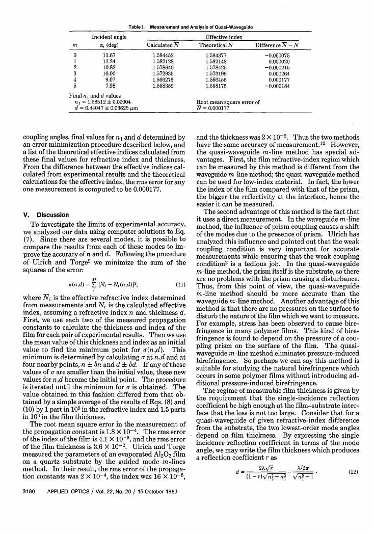
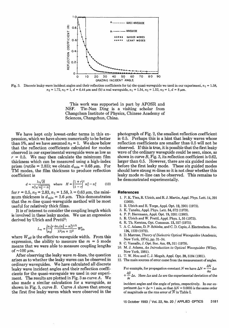
Fig. 3. Discrete leaky-wave incident angles and their reflection coefficients for (a) the quasi-waveguide we used in our experiment, n1 = 1.58,n2 = 1.72, n3 = 1, d = 6.44 pm and (b) a real waveguide, ni = 1.54, n 2 = 1.52, n3 = 1, d = 8 ,m.
This work was supported in part by AFOSR andNSF. Tie-Nan Ding is a visiting scholar fromChangchun Institute of Physics, Chinese Academy ofSciences, Changchun, China.
We have kept only lowest-order terms in this ex-pression, which we have shown numerically to be betterthan 5%, and we have assumed n 3 = 1. We show belowthat the reflection coefficients calculated for modesobserved in our experimental waveguide were as low asr = 0.5. We may then calculate the minimum filmthickness which can be measured using a high-indexprism (rutile = 2.83); we obtain dmin = 0.68 ,um. ForTM modes, the film thickness to produce reflectioncoefficient is
d 2 / where H = (1+ n2nni 2 n,2 1__r ) 2(13)
for r = 0.5, n2 = 2.83, n1 = 1.58, X = 0.63 Am, the mini-mum thickness is dmin = 2.6 Aum. This demonstratesthat the m-line quasi-waveguide method will be mostuseful for relatively thick films.
It is of interest to consider the coupling length whichis involved in these leaky modes. We use an expressionderived by Ulrich and Prettl5 :
Lm = (cp 4n,(n2 - n W f 3nf21 X2(M + 1)2
where Weff is the effective waveguide width. From thisexpression, the ability to measure the m = 5 modemeans that we were able to measure coupling lengthsof -100 jum.
After observing the leaky wave mr-lines, the questionarises as to whether the leaky waves can be observed inordinary waveguides. We have calculated all discreteleaky wave incident angles and their reflection coeffi-cients for the quasi-waveguide we used in our experi-ment. The results are plotted in Fig. 3 as curve A. Wealso made a similar calculation for a waveguide, asshown in Fig. 3, curve B. Curve A shows that amongthe first five leaky waves which were observed in the
photograph of Fig. 2, the smallest reflection coefficientis 0.5. Perhaps this is a hint that leaky waves whosereflection coefficients are smaller than 0.5 will not beobserved. If this is true, it is possible that the first leakywave of the ordinary waveguide could be seen, since, asshown in curve B, Fig. 3, its reflection coefficient is 0.62,larger than 0.5. However, there are six guided modesbefore the first leaky mode. These six guided modesshould have strong mr-lines so it is not clear whether thisleaky mode mr-line can be observed. This remains tobe demonstrated experimentally.
References1. P. K. Tien, R. Ulrich, and R. J. Martin, Appl. Phys. Lett. 14,291
(1969).2. R. Ulrich and R. Torge, Appl. Opt. 12, 2901 (1973).3. K. Tanaka, Appl. Phys. Lett. 34, 672 (1979).4. P. P. Herrmann, Appl. Opt. 19, 3261 (1980).5. R. Ulrich and W. Prettl, Appl. Phys. 1, 55 (1973).6. R. Th. Kersten, Opt. Commun. 13, 327 (1975).7. A. C. Adams, D. P. Schinke, and C. D. Capio, J. Electrochem. Soc.
126, 1539 (1979).8. D. Marcuse, Theory of Dielectric Optical Waveguides (Academic,
New York, 1974), pp. 31-34.9. C. Vassallo, J. Opt. Soc. Am. 69, 311 (1979).
10. M. J. Adams, An Introduction to Optical Waveguides (Wiley,New York, 1981).
11. T. W. Hou and C. J. Mogab, Appl. Opt. 20, 3184 (1981).12. The main sources of error come from the measurement of angles.
For example, for propagation constant N we have AN =- Aa
+ - Ae. Here Aa and Ae are the experimental deviation of the
incident angles and the angle of prism, respectively. In our ex-periment Aa Ae 1 min, so that AN = 0.0003 is the same orderof magnitude as the rms error of N in Table I.