MEB II Manual MEB II Installation and Programming Manual This manual covers the MEB II Modbus Plus to Ethernet Bridge. Effective: January 10, 2013 Niobrara Research & Development Corporation P.O. Box 3418 Joplin, MO 64803 USA Telephone: (800) 235-6723 or (417) 624-8918 Facsimile: (417) 624-8920 http://www.niobrara.com
Transcript
MEB II Manual
MEB IIInstallation and Programming Manual
This manual covers the MEB II Modbus Plus to Ethernet Bridge.
Effective: January 10, 2013
Niobrara Research & Development CorporationP.O. Box 3418 Joplin, MO 64803 USA
Telephone: (800) 235-6723 or (417) 624-8918Facsimile: (417) 624-8920http://www.niobrara.com
Modicon, Square D, SY/MAX, Compact, Quantum, M340, Momentum, Premium are trademarks of Schneider-Electric.
Setting the IP Address.......................................................................13Setting the Subnet Mask...................................................................14Setting the Default Gate...................................................................14Ethernet Connection.........................................................................14
Modbus Plus..........................................................................................17Modbus Plus Configuration..............................................................17Modbus Plus Connection..................................................................18Modbus Plus Lights..........................................................................20
Serial Ports............................................................................................21RS-232 Ports.....................................................................................21RS-485 Ports.....................................................................................23
Software Installation.............................................................................25Updating the MEBII Firmware.............................................................26
Updating Firmware through the Web server....................................26Updating Firmware using RPCLOAD.............................................27
Modbus to SY/MAX Translations....................................................47SY/MAX to Modbus Translations....................................................48Error Translations.............................................................................48
PowerLogic Serial Modes.....................................................................586 Hot MB+ Operation..................................................................................60
Automatic Redundant Operation...........................................................60Requirements and Restrictions.........................................................60“Primary” Unit Configuration Procedure.........................................61“Secondary” Unit Configuration Procedure.....................................62Example............................................................................................63
Reasons for Automatic Switchover.......................................................64Hot MB+ Statistics and Information Registers.....................................64
Serial Number...................................................................................66MB+ Global Data.............................................................................66Controlled Switchover......................................................................66
7 Front Panel Operation...............................................................................67Keypad Buttons.....................................................................................67LCD Screen...........................................................................................67
Splash Screen....................................................................................67Main Menu Screen...........................................................................68
Configuration Menu..............................................................................68Comms Menu Screen.......................................................................69Ethernet Configuration Menu...........................................................69IP Addr Screen..................................................................................70Subnet Mask Screen.........................................................................70 Default Gate Screen.........................................................................71IP Source Screen...............................................................................71Ethernet Protocol Screen..................................................................72 Ethernet Drop Screen......................................................................72Modbus Route Screen.......................................................................73IP Route Screen................................................................................74Ethernet Mode Screen......................................................................75Serial Port Menu...............................................................................76Port 1 Menu......................................................................................76Modbus Plus Edit Screen..................................................................77Display Edit Screen..........................................................................78
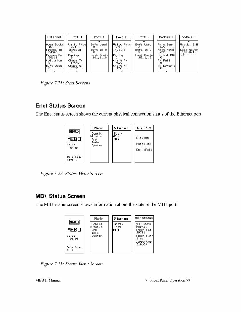
Status Menu Screens.............................................................................78Stats Screen......................................................................................78
iv Contents
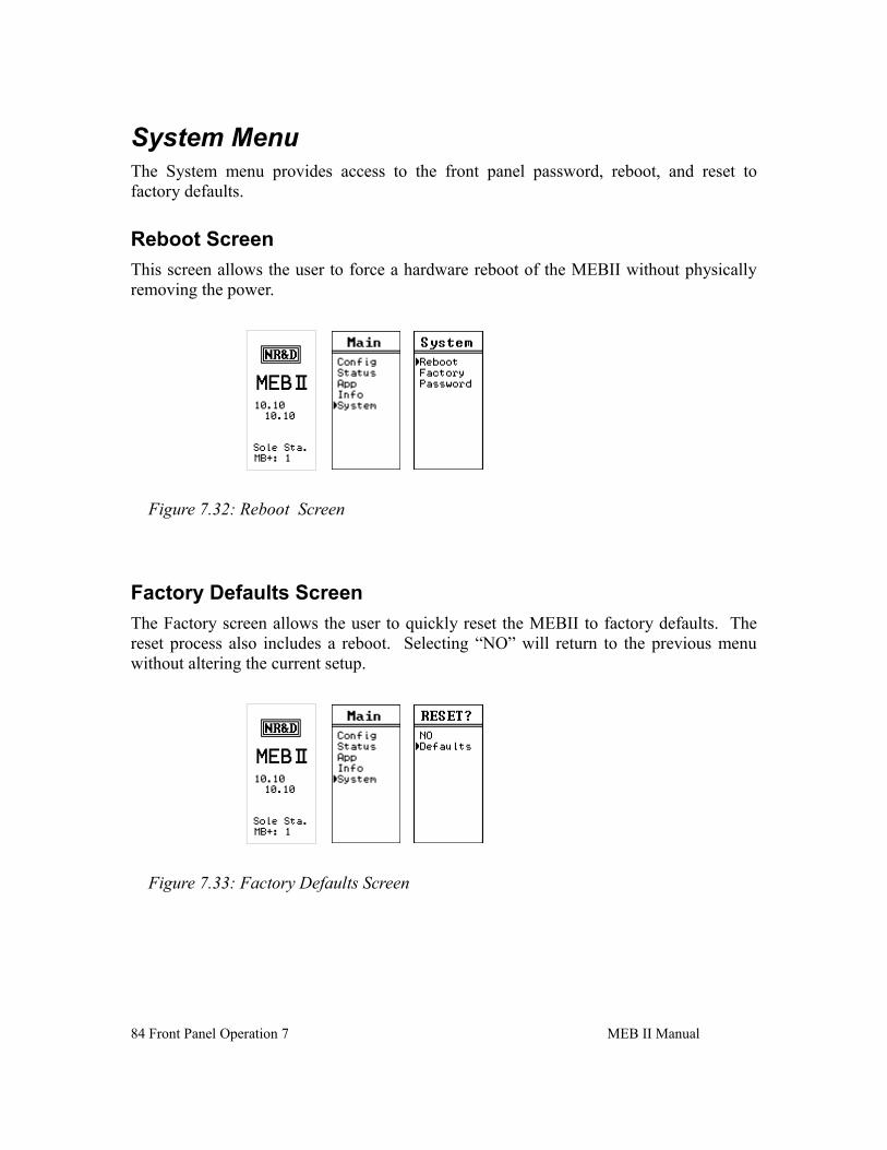
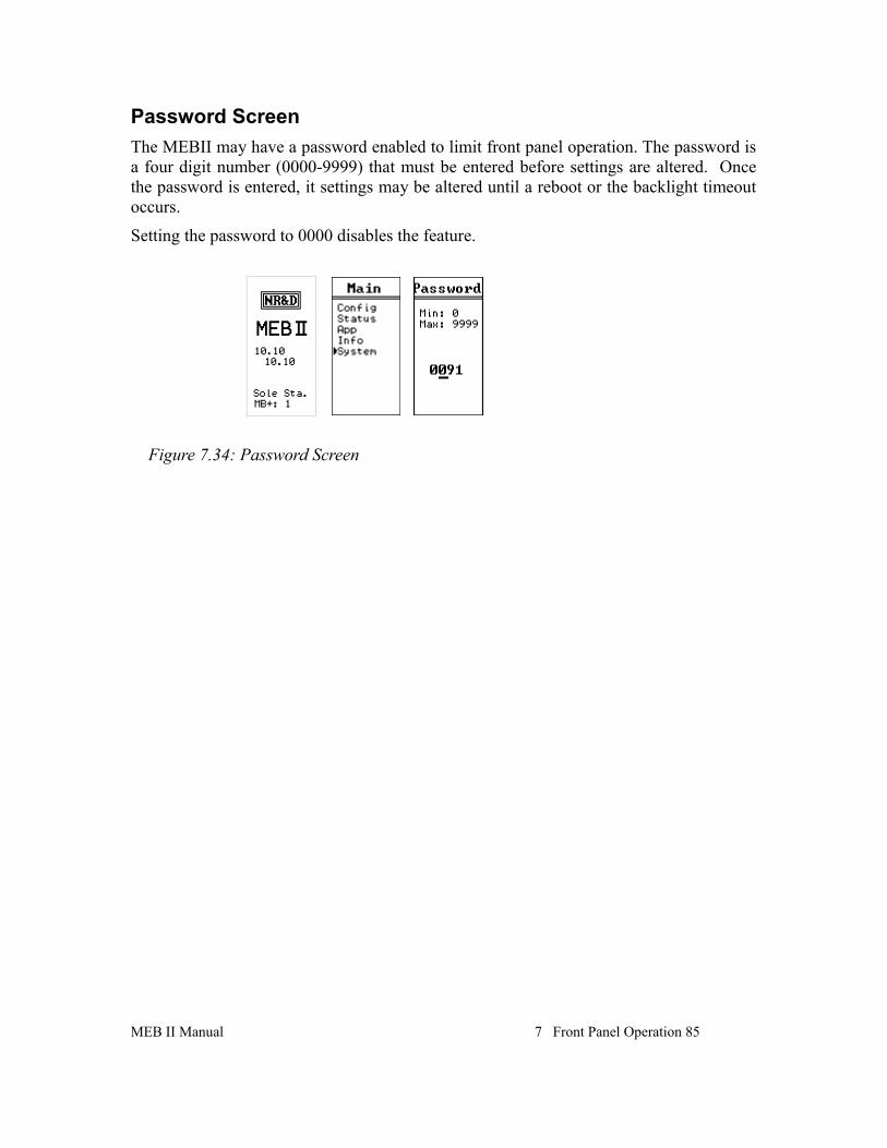
Enet Status Screen............................................................................79MB+ Status Screen...........................................................................79
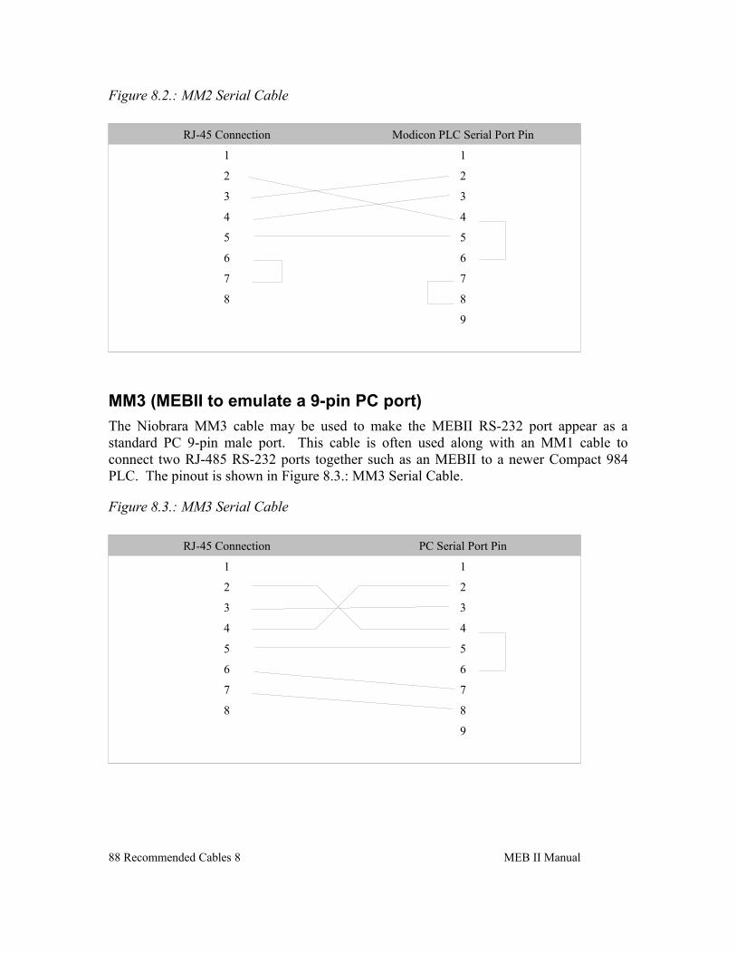
MM1 (PC to MEBII)........................................................................87MM2 (Modicon PLC to MEBII)......................................................87MM3 (MEBII to emulate a 9-pin PC port).......................................88
RS-485 Cables.......................................................................................89MU7 (MEBII to SY/MAX)..............................................................89MEBII Master to 4-wire RS-485 Slaves..........................................89MEBII to 2-wire RS-485..................................................................90
9 Web Server................................................................................................93Login.....................................................................................................93Home ....................................................................................................95Configuration........................................................................................95
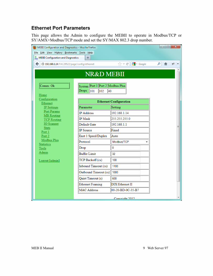
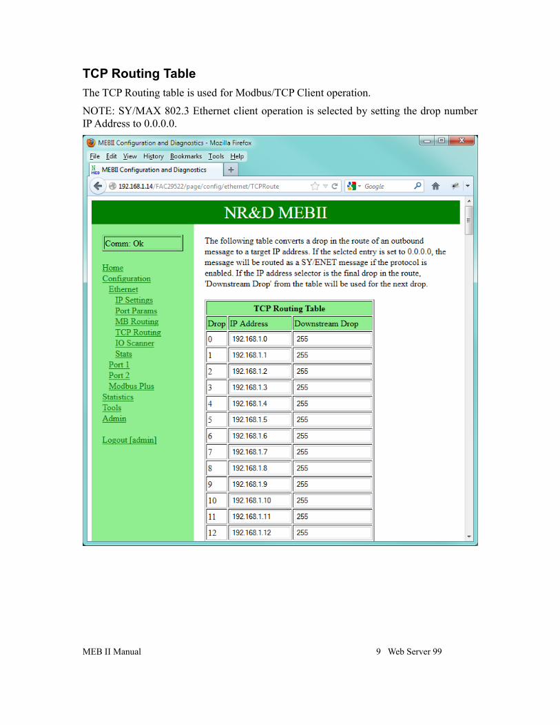
Ethernet.............................................................................................95IP Settings.........................................................................................96Ethernet Port Parameters..................................................................97Modbus Routing for Ethernet Port...................................................98TCP Routing Table...........................................................................99I/O Scanner.....................................................................................100
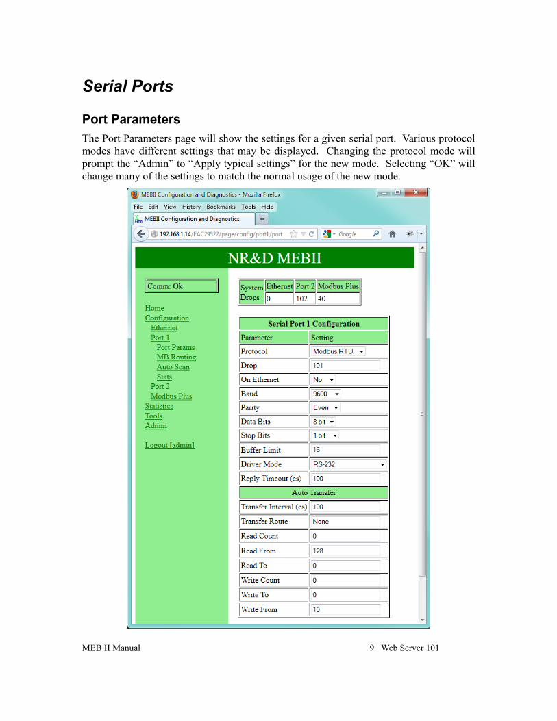
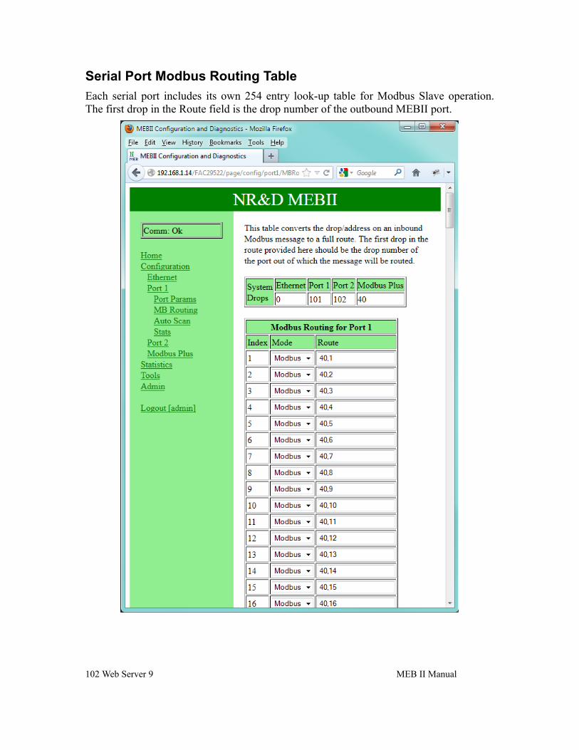
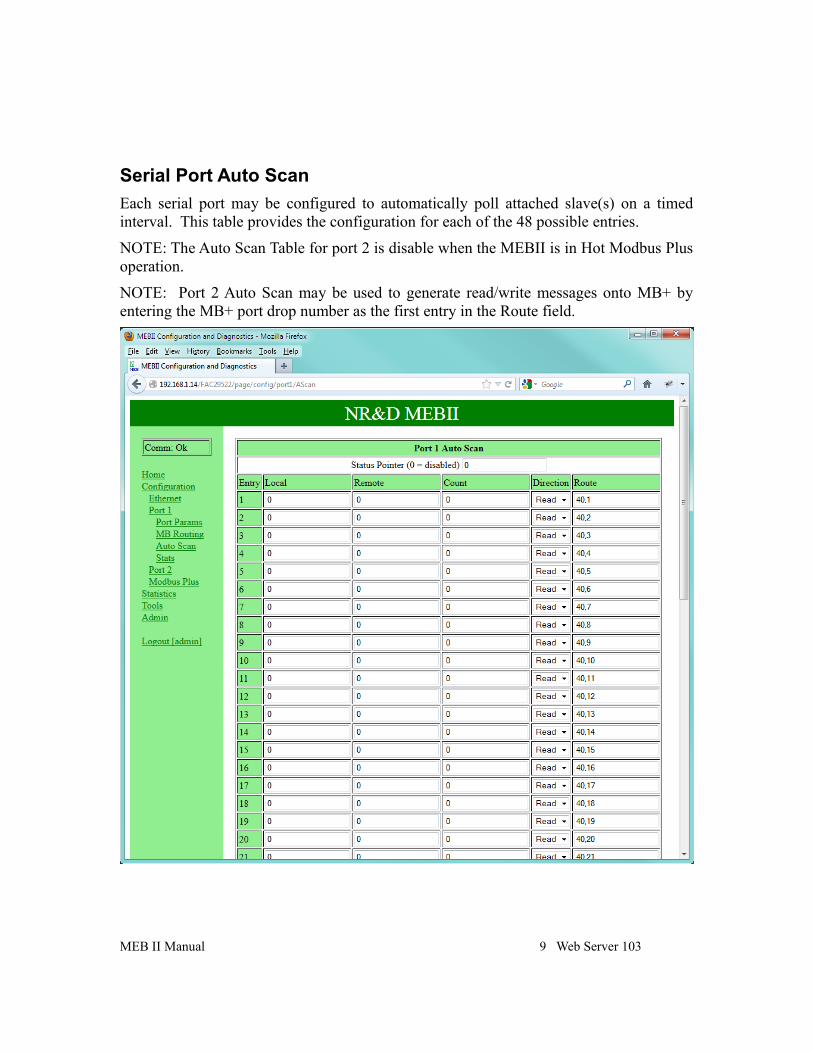
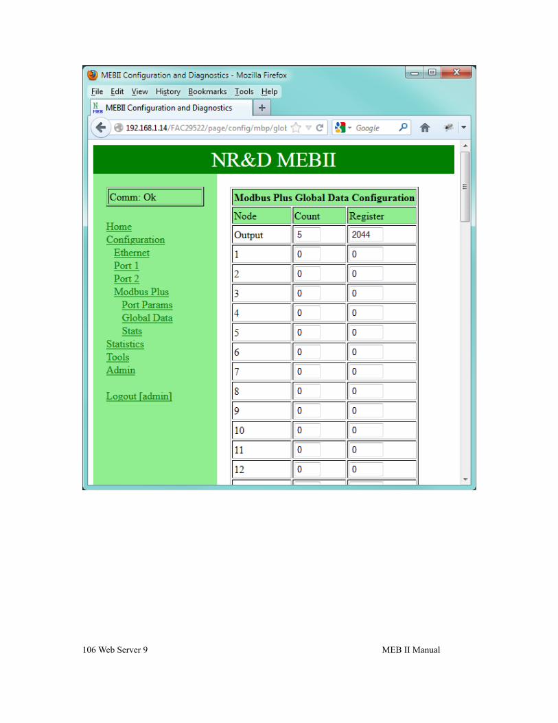
Serial Ports..........................................................................................101Port Parameters...............................................................................101Serial Port Modbus Routing Table.................................................102Serial Port Auto Scan......................................................................103Modbus Plus Port Parameters.........................................................104Modbus Plus Global Data...............................................................105
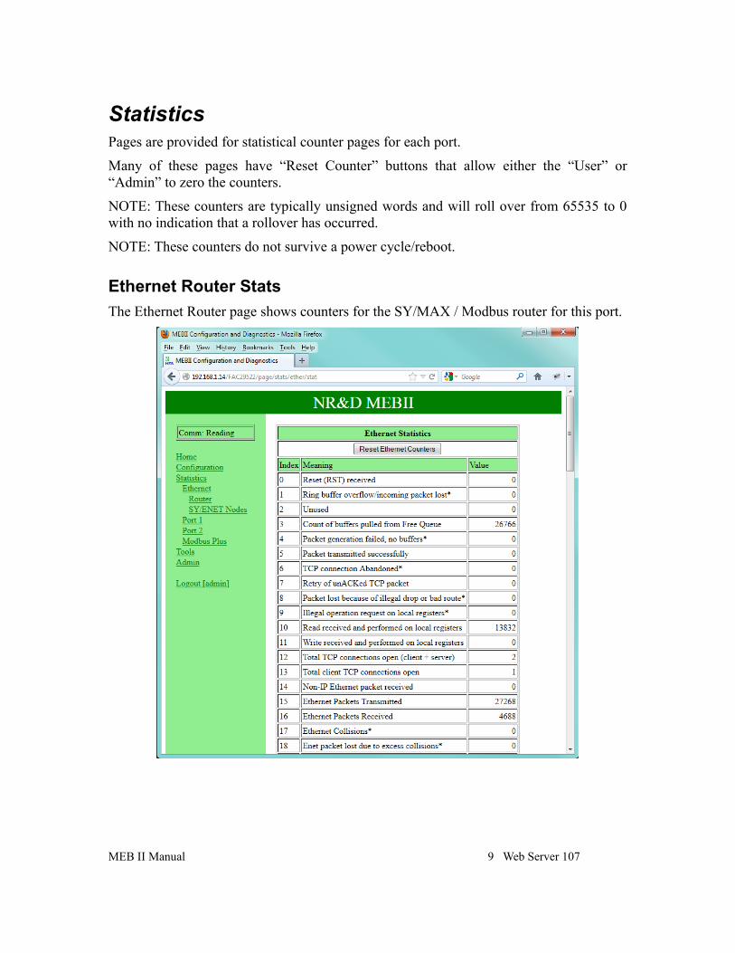
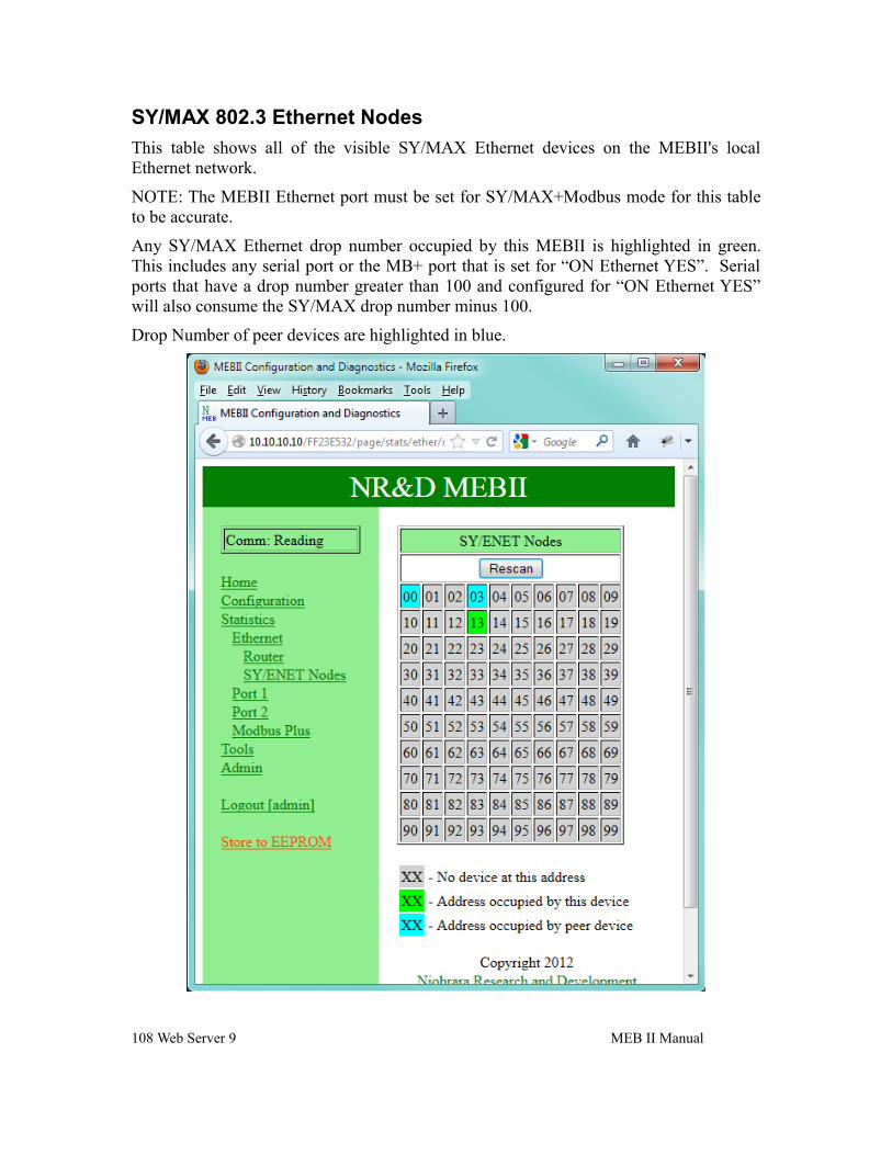
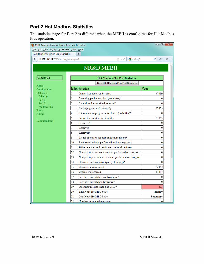
Statistics..............................................................................................107Ethernet Router Stats......................................................................107SY/MAX 802.3 Ethernet Nodes.....................................................108Serial Port ......................................................................................109Port 2 Hot Modbus Statistics..........................................................110
Contents v
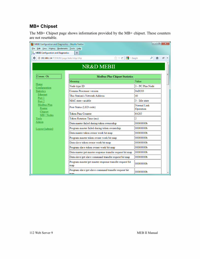
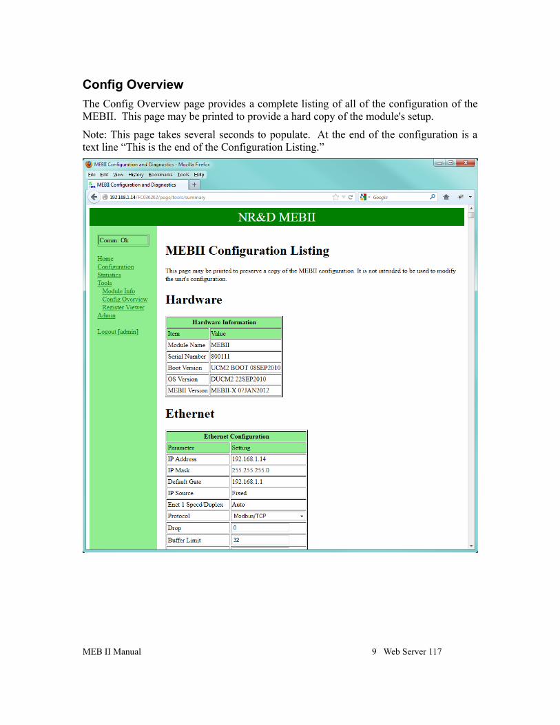
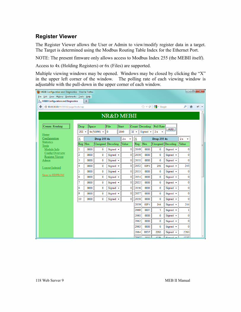
Modbus Plus Router........................................................................111MB+ Chipset...................................................................................112Modbus Plus Nodes........................................................................113Module Info....................................................................................116Config Overview............................................................................117Register Viewer...............................................................................118
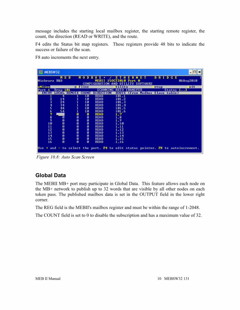
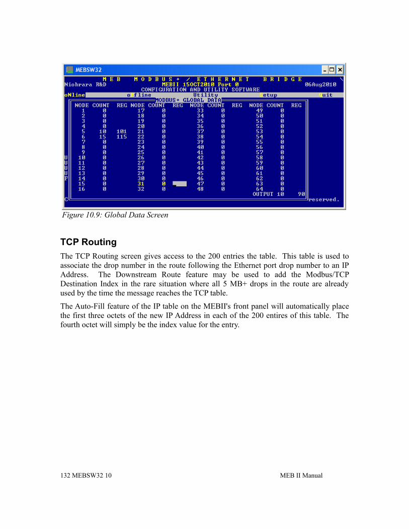
Edit port parameters.......................................................................129Edit Modbus routing.......................................................................130Auto Scan Edit................................................................................130Global Data.....................................................................................131TCP Routing...................................................................................132
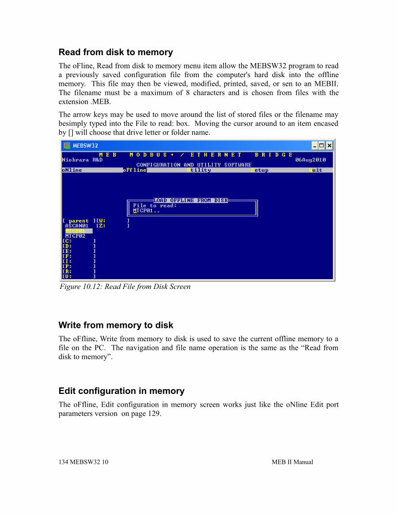
offline Menu........................................................................................133Read from disk to memory.............................................................134Write from memory to disk............................................................134Edit configuration in memory........................................................134edit Modbus Routing......................................................................135edit Global data table......................................................................135edit TCP routing table.....................................................................135Send memory to module.................................................................135Fetch memory from module...........................................................135Print configuration in memory.......................................................135Delete configuration file.................................................................135Copy offline to module flash..........................................................135Quit offline functions......................................................................136
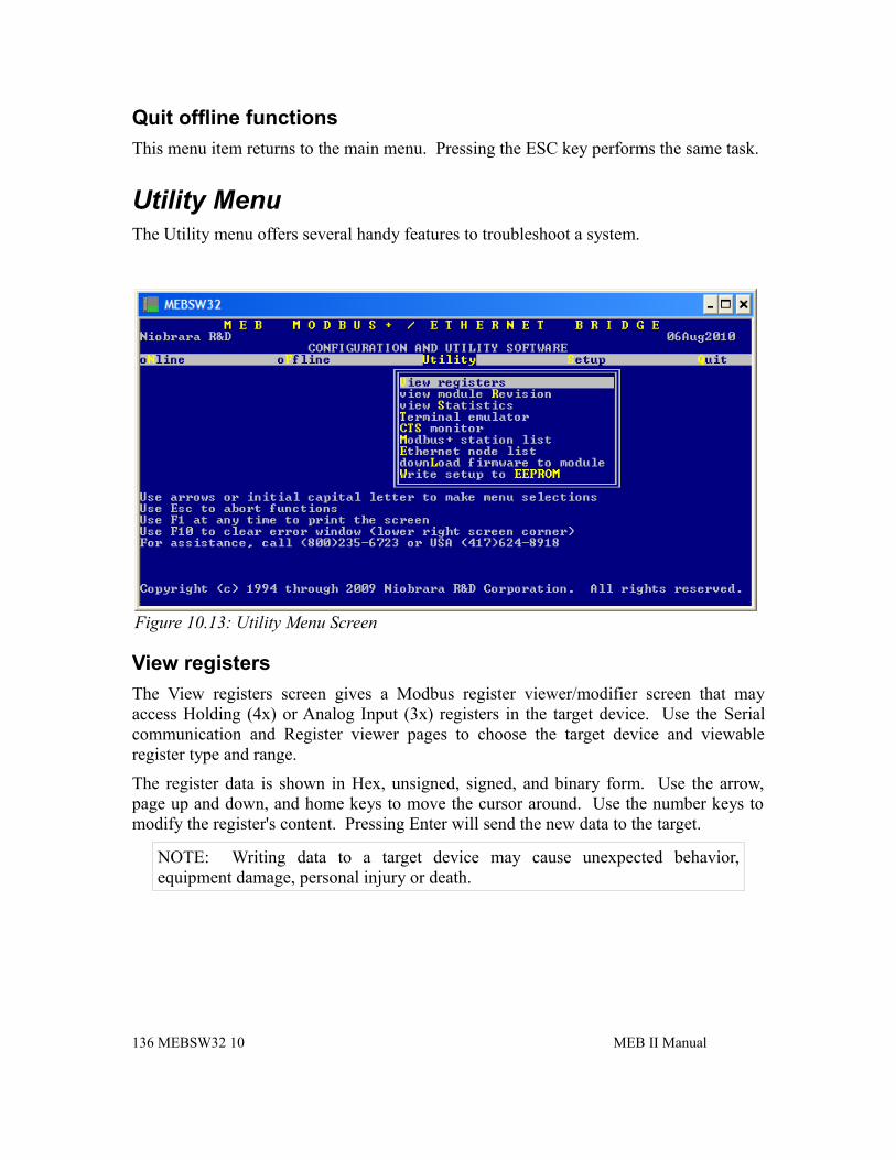
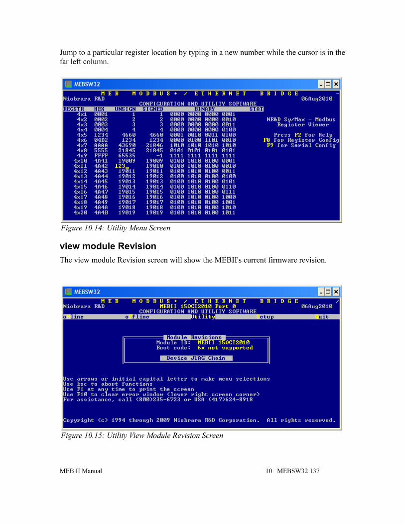
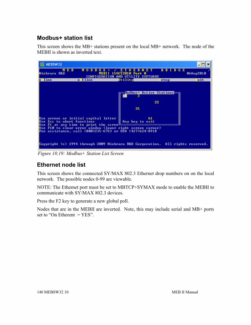
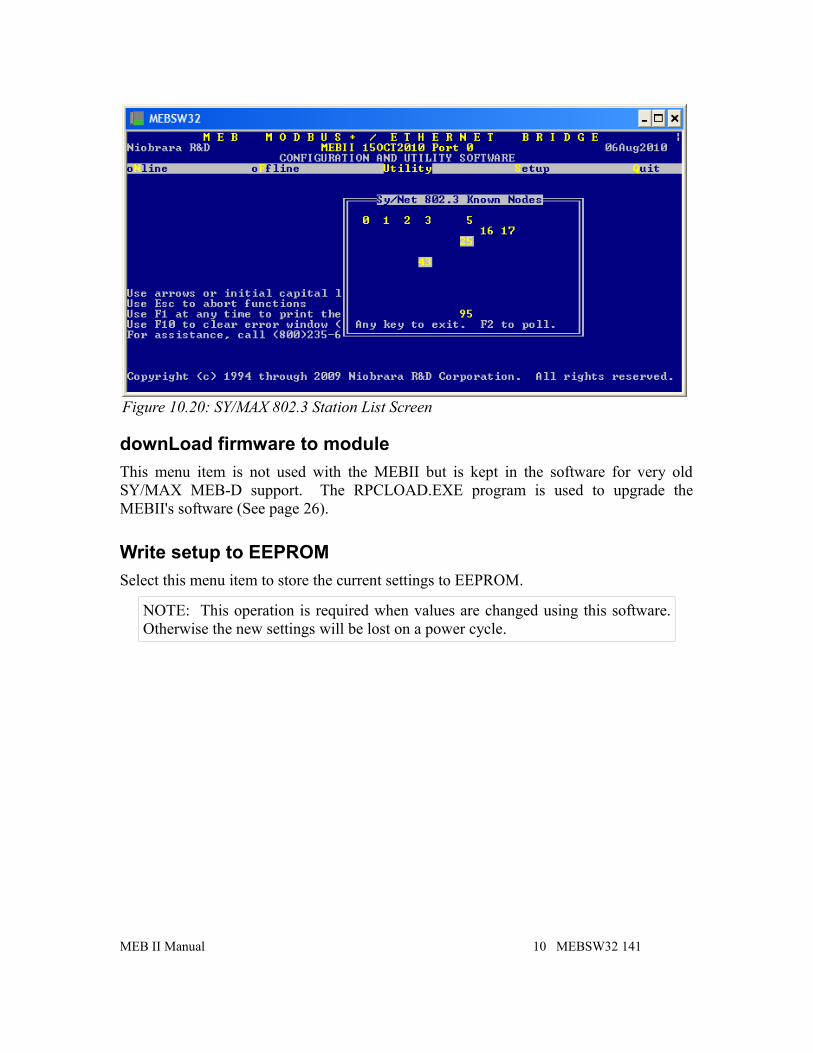
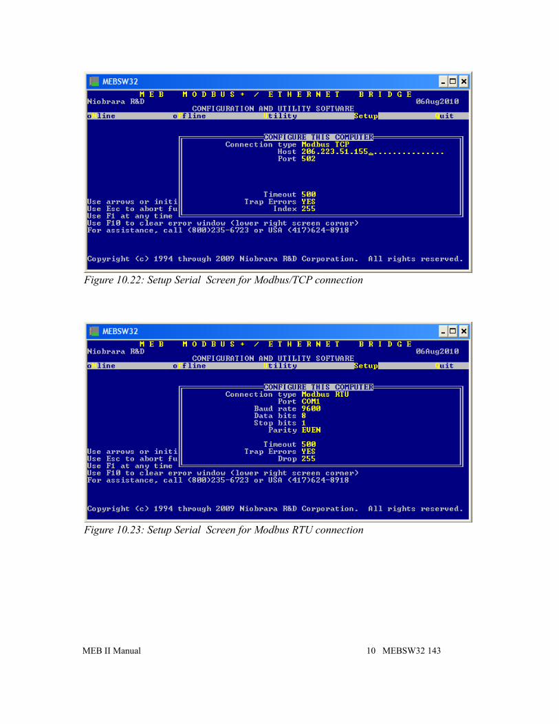
Utility Menu........................................................................................136View registers.................................................................................136view module Revision....................................................................137view Statistics.................................................................................138Terminal emulator...........................................................................139CTS monitor...................................................................................139Modbus+ station list.......................................................................140Ethernet node list............................................................................140downLoad firmware to module......................................................141
vi Contents
Write setup to EEPROM................................................................141Setup Menu.........................................................................................142
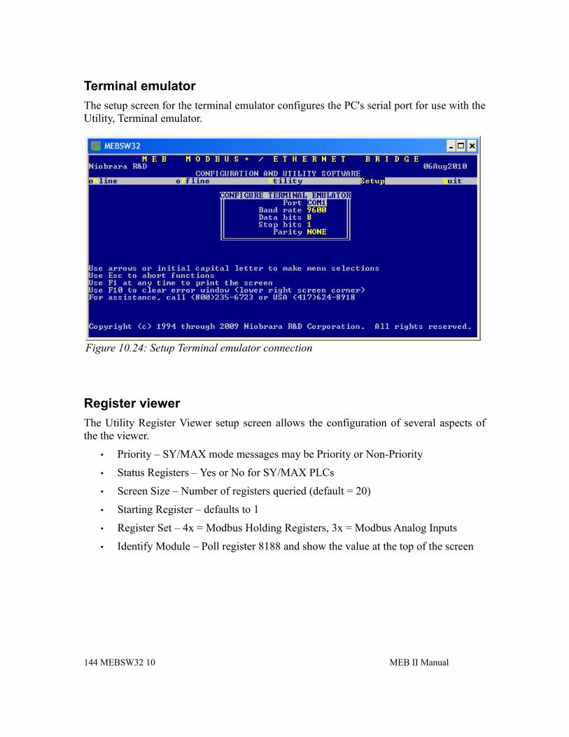
Serial communication.....................................................................142Terminal emulator...........................................................................144Register viewer...............................................................................144
The Niobrara MEBII is a stand-alone DIN rail mount Modbus Plus to Ethernet Bridge. It features a redundant cable Modbus Plus (MB+) port, at leaset one 10/100BaseTX Ethernet port, and two isolated serial ports. The MEBII allows simultaneous pass-through routing data messages from Modbus/TCP Ethernet, MB+, and Modbus serial between all ports. Full support of PLC programming message pass-through is also provided on all communication ports including Unity Pro, Concept, ProWORX, and Modsoft.
MEB II Manual 9
Figure 1.1:MEBII Front Panel
KeypadDual Cable
Modbus Plus
100BaseTXEthernet24VDC
Power
Port 1(RS-232)
LCD showingIP Address,MB+ Node
Port 2 (RS-232)
Port 1(RS-485) Port 2
(RS-485)
The MEBII features at least one 100BaseTX Ethernet port that supports Modbus/TCP as both a client and a server at the same time. The MEBII can support up to 64 simultaneous Modbus/TCP connections. A routing table is used to map the incoming Modbus/TCP Destination Index (Slave Address) from a client to a downstream route that determines where the message is directed. This route may point to a PLC on MB+, a slave on one of the MEB's serial ports, or even back out the Ethernet port to a different device. The Ethernet port also supports the older SY/MAX 802.3 protocol for smoothly integrating legacy Square D Model 650 and 450 PLCs into a Modbus/TCP system.
The MEBII+201 model includes two 100BaseTX Ethernet ports that support Rapid Spanning Tree Protocol (RSTP) allowing the MEBII to be used in a copper ring network for redundant Ethernet cable connections. It may also be used in a daisy-chain Ethernet network as well.
The Modbus Plus port supports dual-cable redundant MB+ networking but may simply be used in a single-cable system by leaving one of the ports open. The standard 5-drop MB+ routing structure is supported allowing full access to MB+ devices on the local network or through Modicon Bridge Plus and Bridge Mux devices.
There are two isolated serial ports on the MEBII. Each port may be selected to use its RJ-45 connector for RS-232 or a removable 5-pin screw connector for RS-485. The RS-485 port may operate in 4-wire RS-422, 4-wire RS-485, or 2-wire RS-485 modes with selectable termination and bias. The two serial ports may be independently configured for one of 18 different protocols including Modbus RTU, Modbus ASCII, and SY/MAX. The default mode supports Modbus RTU and can dynamically switch between being a master or a slave.
The MEBII features a front panel backlit LCD and keypad that may be used for configuration and troubleshooting. The IP Address, MB+ node address and most serial port settings may be configured through this interface which may be password protected to prevent unauthorized changes.
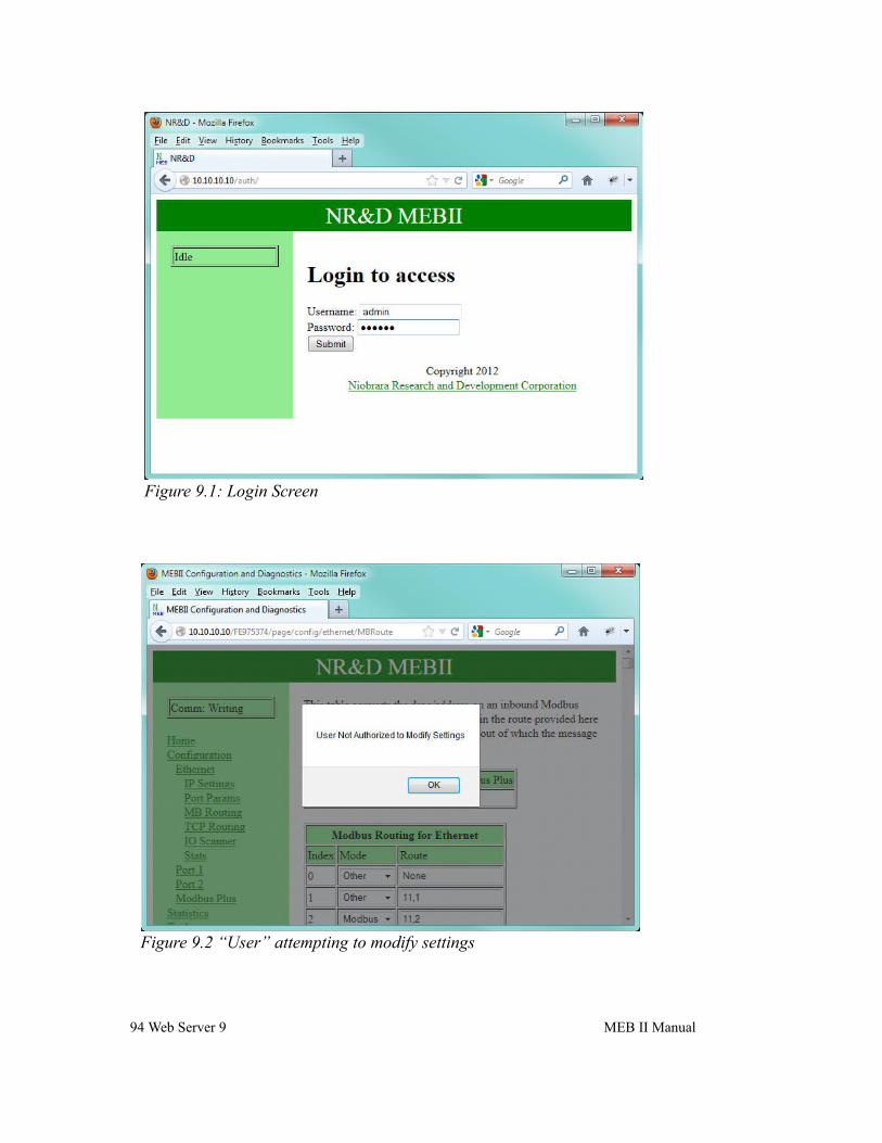
A built-in web server is included in the MEBII. This password protected, AJAX Javascript enabled server allows two user levels for configuration, backup/restore, troubleshooting, and even firmware updating – all from a standard browser.
The MEBII also includes a “Hot MB+” mode that allows two MEBII units to work together to provide an automatic fully redundant primary/standby system for high availability systems.
10 Introduction 1 MEB II Manual
2 InstallationWARNING: Do not connect the MEB II to any Ethernet or MB+ network before configuring the appropriate network addresses. Duplicate network address may lead to improper network communication, equipment damage, injury, or death.
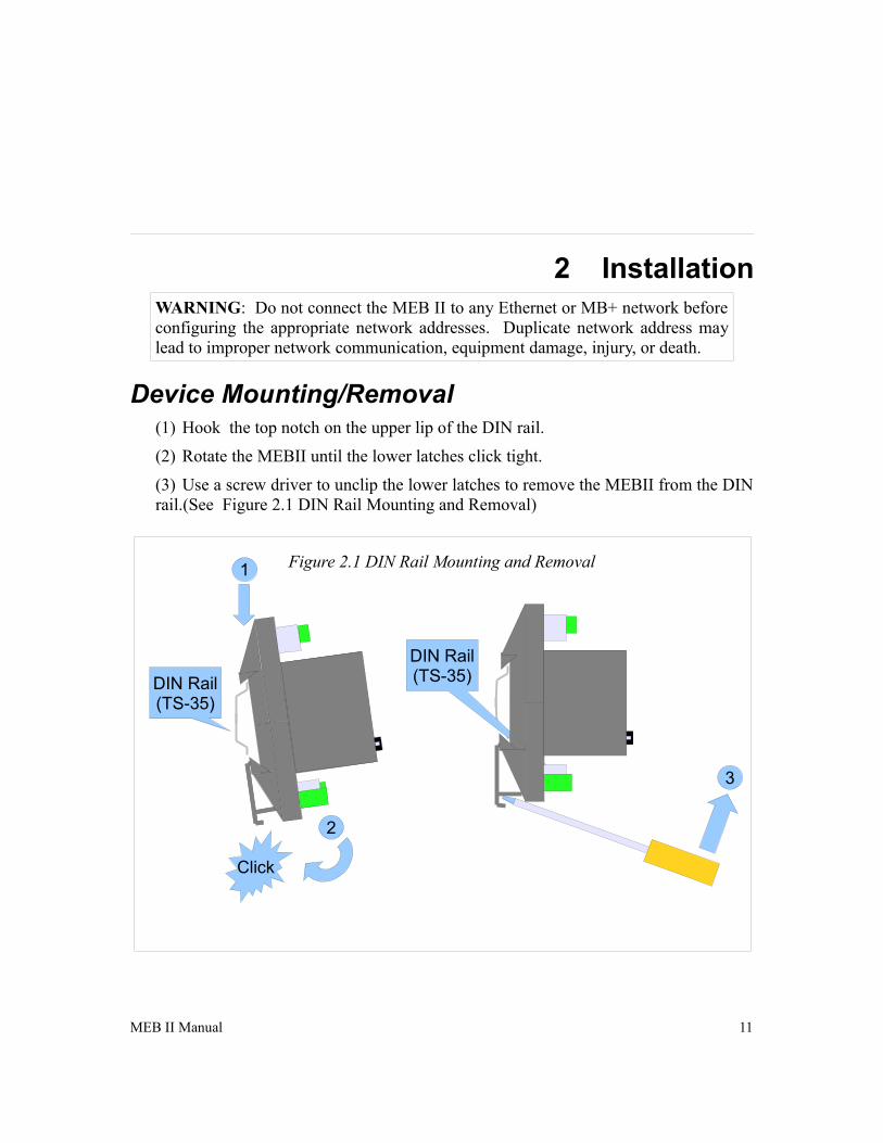
Device Mounting/Removal(1) Hook the top notch on the upper lip of the DIN rail.
(2) Rotate the MEBII until the lower latches click tight.
(3) Use a screw driver to unclip the lower latches to remove the MEBII from the DIN rail.(See Figure 2.1 DIN Rail Mounting and Removal)
MEB II Manual 11
Figure 2.1 DIN Rail Mounting and Removal
3
DIN Rail(TS-35)DIN Rail
(TS-35)
Click
1
2
Power SupplyConnect a suitable 24VDC power to the three position removable connector. The MEB II requires a 5W minimum supply and will operate on 9-30Vdc but 24Vdc is recommended. (See Figure 2.2 Power Supply Diagram) An external fuse is recommended. Typical power supply wire colors are:
• Red = 24Vdc (+)
• Black = 24Vdc (-)
• Green = Earth Ground
12 Installation 2 MEB II Manual
Figure 2.2 Power Supply Diagram
DIN Rail(TS-35)
Fuse Disconnect
24Vdc Power Supply
Ethernet
Setting the IP Address
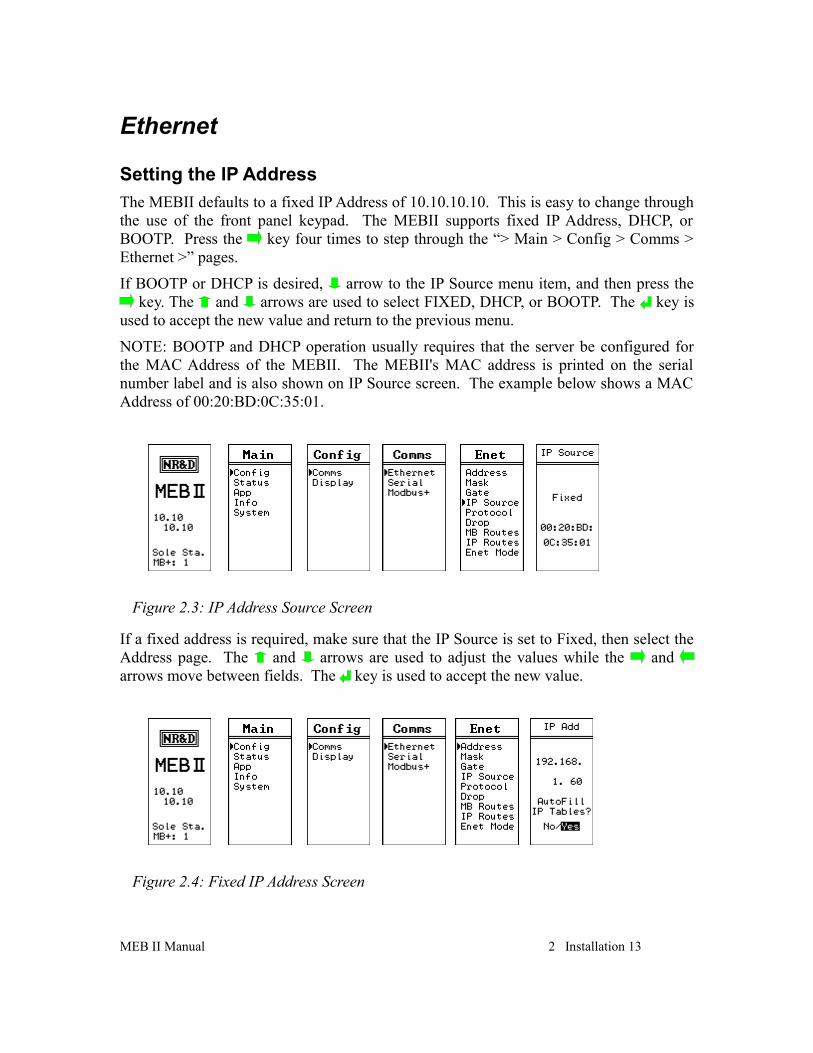
The MEBII defaults to a fixed IP Address of 10.10.10.10. This is easy to change through the use of the front panel keypad. The MEBII supports fixed IP Address, DHCP, or BOOTP. Press the key four times to step through the “> Main > Config > Comms > Ethernet >” pages.
If BOOTP or DHCP is desired, arrow to the IP Source menu item, and then press the key. The and arrows are used to select FIXED, DHCP, or BOOTP. The key is
used to accept the new value and return to the previous menu.
NOTE: BOOTP and DHCP operation usually requires that the server be configured for the MAC Address of the MEBII. The MEBII's MAC address is printed on the serial number label and is also shown on IP Source screen. The example below shows a MAC Address of 00:20:BD:0C:35:01.
If a fixed address is required, make sure that the IP Source is set to Fixed, then select the Address page. The and arrows are used to adjust the values while the and arrows move between fields. The key is used to accept the new value.
MEB II Manual 2 Installation 13
Figure 2.3: IP Address Source Screen
Figure 2.4: Fixed IP Address Screen
The “Autofill IP Tables?” offers the automatic filling of the TCP client table. Each of the 200 entries in the TCP table will be set to the first three octets of the MEBII's IP Address and the last octet will be set to the index number 0-199.
Setting the Subnet Mask
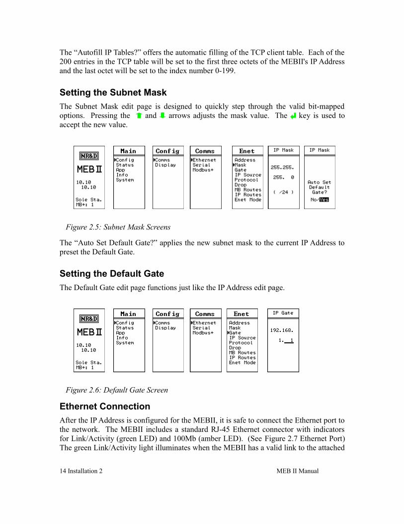
The Subnet Mask edit page is designed to quickly step through the valid bit-mapped options. Pressing the and arrows adjusts the mask value. The key is used to accept the new value.
The “Auto Set Default Gate?” applies the new subnet mask to the current IP Address to preset the Default Gate.
Setting the Default Gate
The Default Gate edit page functions just like the IP Address edit page.
Ethernet Connection
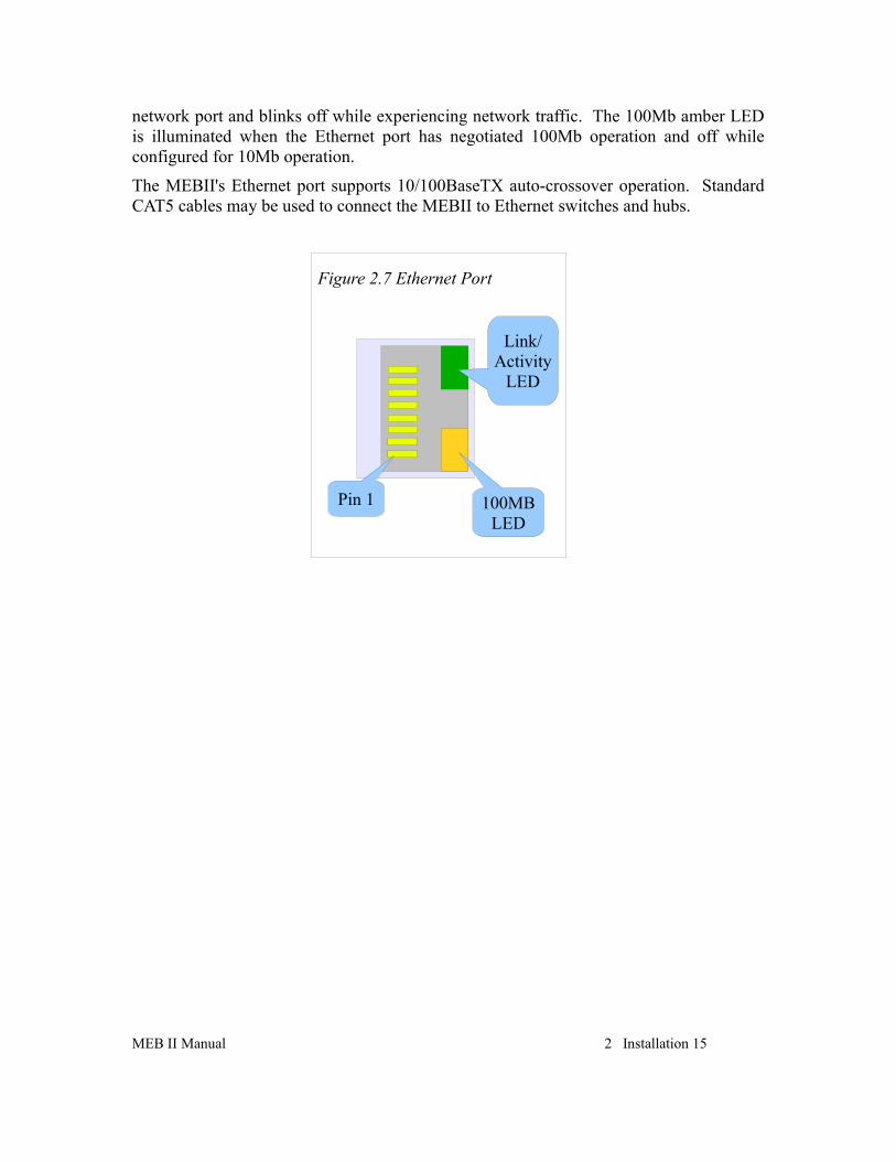
After the IP Address is configured for the MEBII, it is safe to connect the Ethernet port to the network. The MEBII includes a standard RJ-45 Ethernet connector with indicators for Link/Activity (green LED) and 100Mb (amber LED). (See Figure 2.7 Ethernet Port) The green Link/Activity light illuminates when the MEBII has a valid link to the attached
14 Installation 2 MEB II Manual
Figure 2.5: Subnet Mask Screens
Figure 2.6: Default Gate Screen
network port and blinks off while experiencing network traffic. The 100Mb amber LED is illuminated when the Ethernet port has negotiated 100Mb operation and off while configured for 10Mb operation.
The MEBII's Ethernet port supports 10/100BaseTX auto-crossover operation. Standard CAT5 cables may be used to connect the MEBII to Ethernet switches and hubs.
MEB II Manual 2 Installation 15
Figure 2.7 Ethernet Port
Pin 1 100MBLED
Link/Activity
LED
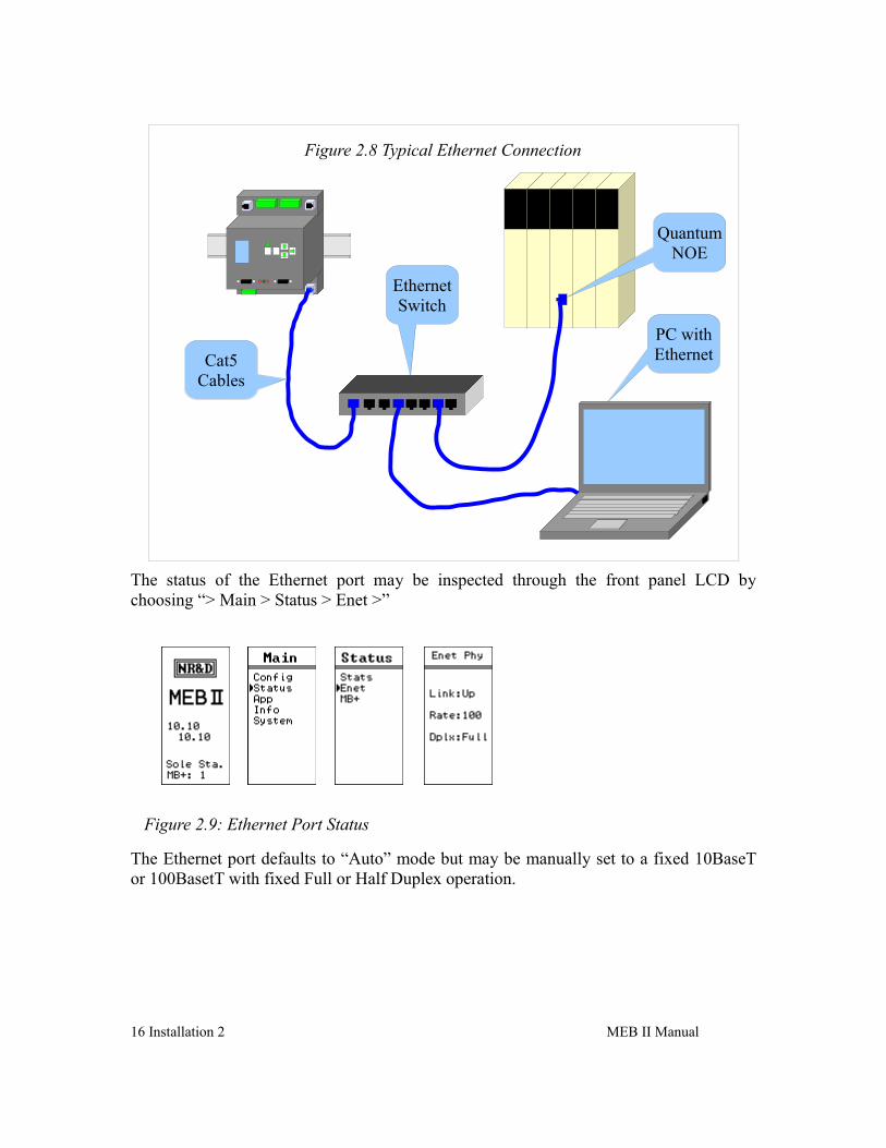
The status of the Ethernet port may be inspected through the front panel LCD by choosing “> Main > Status > Enet >”
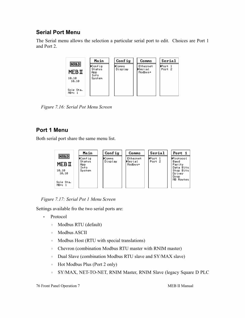
The Ethernet port defaults to “Auto” mode but may be manually set to a fixed 10BaseT or 100BasetT with fixed Full or Half Duplex operation.
16 Installation 2 MEB II Manual
Figure 2.8 Typical Ethernet Connection
QuantumNOE
EthernetSwitch
Cat5Cables
PC withEthernet
Figure 2.9: Ethernet Port Status
Modbus Plus
Modbus Plus Configuration
The Modbus Plus (MB+) node of the MEBII may be assigned an address between 1 and 64 with a default value of 1. This address must be unique within the local MB+ network segment. To edit the MB+ drop number choose:
“> Main > Config > Comms > Modbus+ >“
The and arrows are used to adjust the new MB+ drop. The key is used to accept the new value.
NOTE: If the MEBII is physically connected to the local MB+ network, it will automatically skip MB+ drop numbers that are already in use. The drop numbers of the Ethernet and serial ports will also be skipped if they fall within the valid MB+ range.
After selecting the new MB+ drop number, the screen will change to ask if the user would like to AutoFix the Routing Tables. Choosing Yes will result in the Modbus Routing Tables for the Ethernet and serial ports 1and 2 being updated to include the new drop number of the MB+ port. If No is selected, these tables will not be updated and many of the routes will not longer work properly – they must then be edited manually.
MEB II Manual 2 Installation 17
Figure 2.11: Edit Modbus Plus Drop
Figure 2.10: Ethernet Mode Screen
Modbus Plus Connection
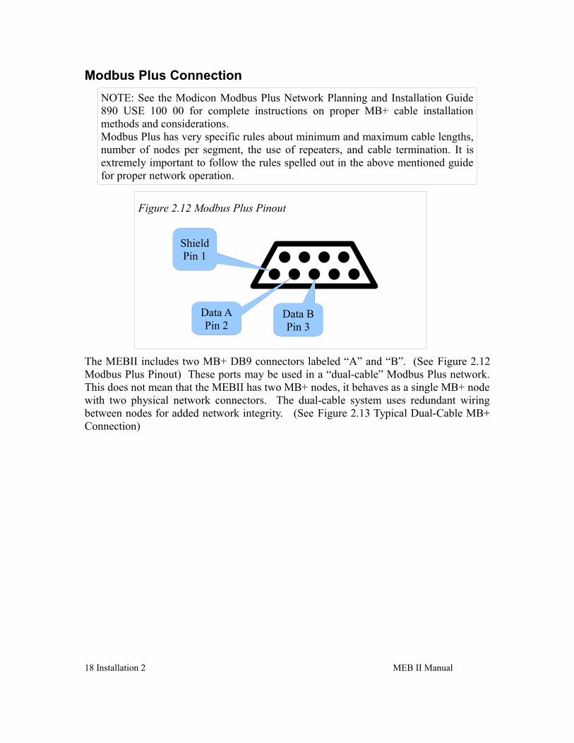
NOTE: See the Modicon Modbus Plus Network Planning and Installation Guide 890 USE 100 00 for complete instructions on proper MB+ cable installation methods and considerations. Modbus Plus has very specific rules about minimum and maximum cable lengths, number of nodes per segment, the use of repeaters, and cable termination. It is extremely important to follow the rules spelled out in the above mentioned guide for proper network operation.
The MEBII includes two MB+ DB9 connectors labeled “A” and “B”. (See Figure 2.12Modbus Plus Pinout) These ports may be used in a “dual-cable” Modbus Plus network. This does not mean that the MEBII has two MB+ nodes, it behaves as a single MB+ node with two physical network connectors. The dual-cable system uses redundant wiring between nodes for added network integrity. (See Figure 2.13 Typical Dual-Cable MB+Connection)
18 Installation 2 MEB II Manual
Figure 2.12 Modbus Plus Pinout
Data BPin 3
Data APin 2
ShieldPin 1
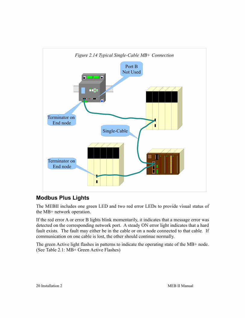
The MEBII may be used in a “single-cable” network by simply connecting the MB+ network to port “A”. (See Figure 2.14 Typical Single-Cable MB+ Connection)
MEB II Manual 2 Installation 19
Figure 2.13 Typical Dual-Cable MB+ Connection
Terminator on End node Terminator on
End node
Terminator on End node
Terminator on End node
Cable B
Cable A
Modbus Plus Lights
The MEBII includes one green LED and two red error LEDs to provide visual status of the MB+ network operation.
If the red error A or error B lights blink momentarily, it indicates that a message error was detected on the corresponding network port. A steady ON error light indicates that a hard fault exists. The fault may either be in the cable or on a node connected to that cable. If communication on one cable is lost, the other should continue normally.
The green Active light flashes in patterns to indicate the operating state of the MB+ node. (See Table 2.1: MB+ Green Active Flashes)
20 Installation 2 MEB II Manual
Figure 2.14 Typical Single-Cable MB+ Connection
Terminator on End node
Terminator on End node
Single-Cable
Port BNot Used
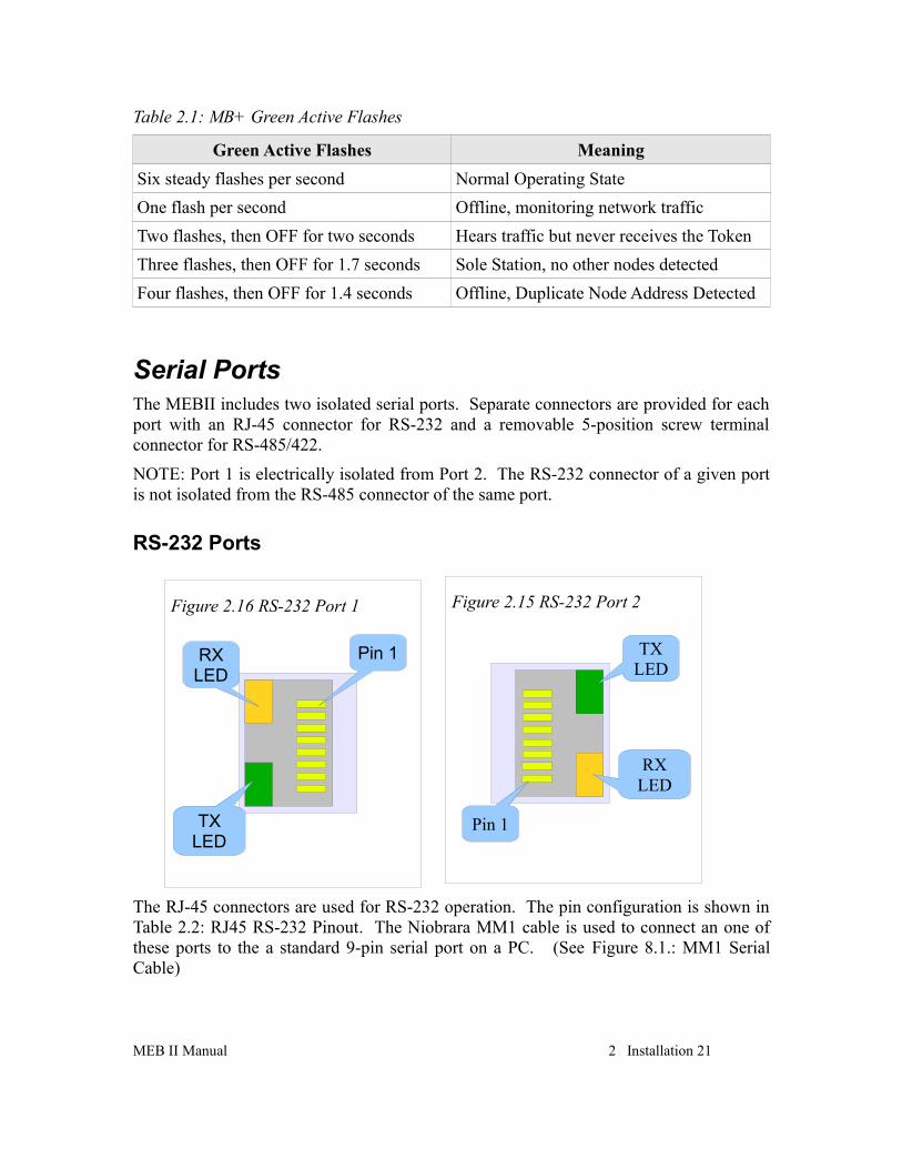
Table 2.1: MB+ Green Active Flashes
Green Active Flashes Meaning
Six steady flashes per second Normal Operating State
One flash per second Offline, monitoring network traffic
Two flashes, then OFF for two seconds Hears traffic but never receives the Token
Three flashes, then OFF for 1.7 seconds Sole Station, no other nodes detected
Four flashes, then OFF for 1.4 seconds Offline, Duplicate Node Address Detected
Serial PortsThe MEBII includes two isolated serial ports. Separate connectors are provided for each port with an RJ-45 connector for RS-232 and a removable 5-position screw terminal connector for RS-485/422.
NOTE: Port 1 is electrically isolated from Port 2. The RS-232 connector of a given port is not isolated from the RS-485 connector of the same port.
RS-232 Ports
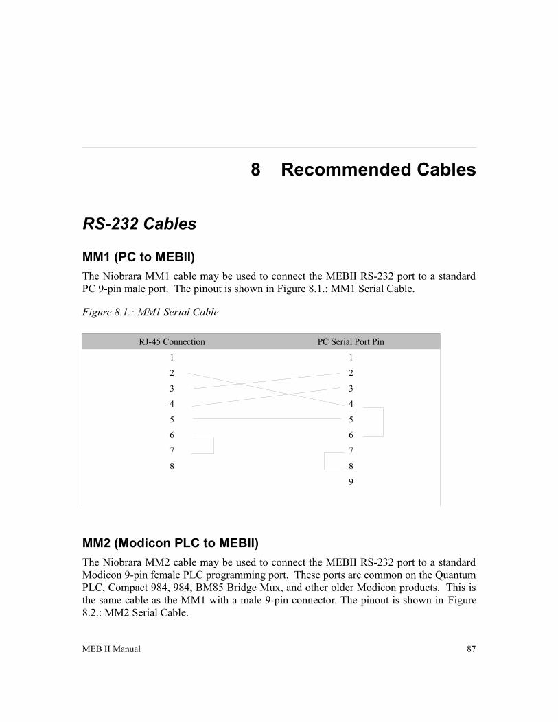
The RJ-45 connectors are used for RS-232 operation. The pin configuration is shown in Table 2.2: RJ45 RS-232 Pinout. The Niobrara MM1 cable is used to connect an one of these ports to the a standard 9-pin serial port on a PC. (See Figure 8.1.: MM1 SerialCable)
MEB II Manual 2 Installation 21
Figure 2.16 RS-232 Port 1 Figure 2.15 RS-232 Port 2
Pin 1
RXLED
TXLED
Pin 1
TXLED
RXLED
Table 2.2: RJ45 RS-232 Pinout
Pin Function
1 No Connection
2 DSR (pulled high)
3 Data TX
4 Data RX
5 Signal GND
6 RTS
7 CTS
8 Chassis GND
22 Installation 2 MEB II Manual
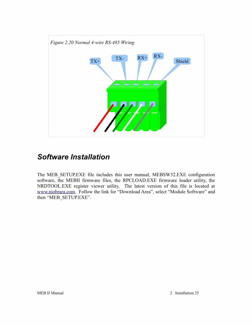
RS-485 Ports
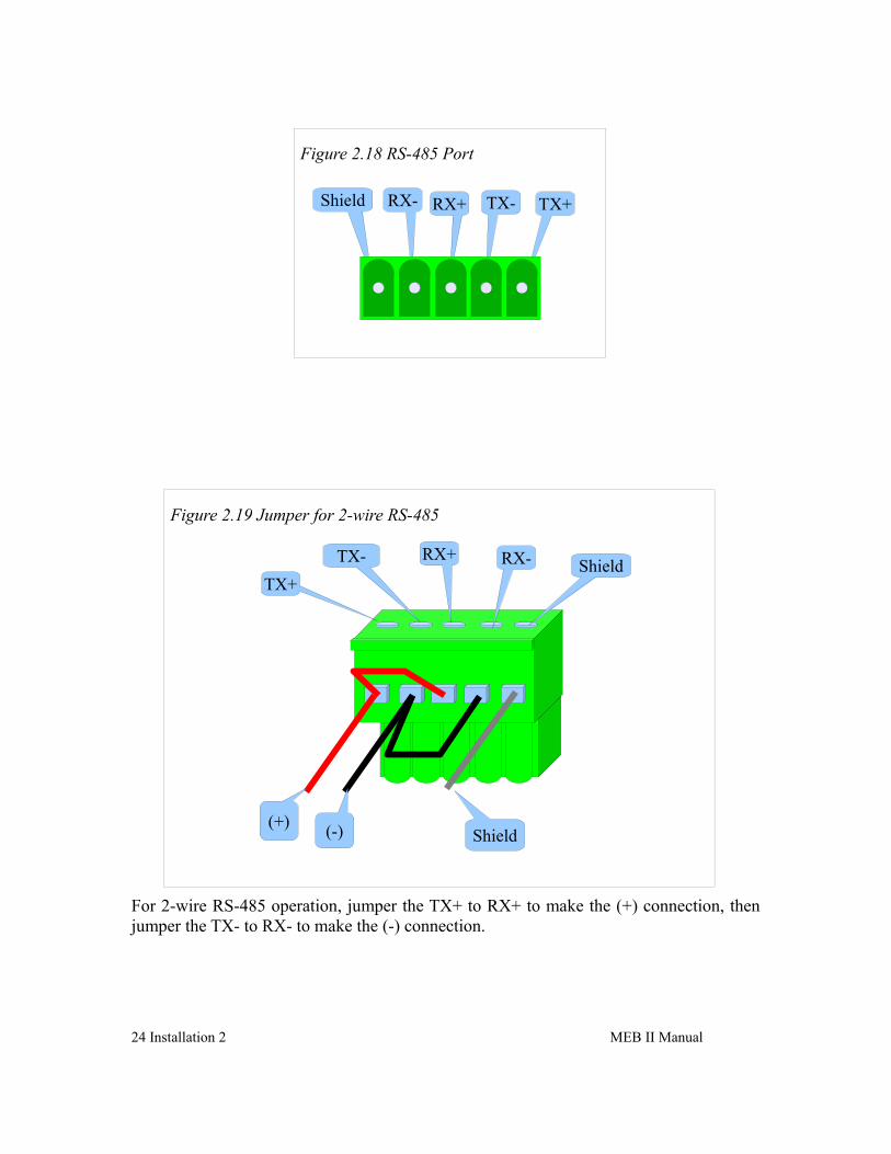
Port 1 and 2 may be used for RS-485 (4-wire or 2-wire) and RS-422 operation. A 5-pin removable screw terminal connector is provided. The pinout is shown in Figure 2.18 RS-485 Port.
Table 2.3: 5-position RS-485 pinout
Pin Function
Shield No internal connection
RX- (-) data into MEBII
RX+ (+) data into MEBII
TX- (-) data out from MEBII
TX+ (+) data out from MEBII
MEB II Manual 2 Installation 23
Figure 2.17 Typical RS-232 Connections
MM1Cable
MM2Cable
Compact 984with 9-pin
RS-232PC with
9-pin RS-232
For 2-wire RS-485 operation, jumper the TX+ to RX+ to make the (+) connection, then jumper the TX- to RX- to make the (-) connection.
24 Installation 2 MEB II Manual
Figure 2.18 RS-485 Port
RX- RX+ TX- TX+Shield
Figure 2.19 Jumper for 2-wire RS-485
ShieldTX+
TX- RX+ RX-
(+)(-) Shield
Software Installation
The MEB_SETUP.EXE file includes this user manual, MEBSW32.EXE configuration software, the MEBII firmware files, the RPCLOAD.EXE firmware loader utility, the NRDTOOL.EXE register viewer utility, The latest version of this file is located at www.niobrara.com. Follow the link for “Download Area”, select “Module Software” and then “MEB_SETUP.EXE”.
Updating the MEBII FirmwareOn occasion it may be necessary to update the operating system of the MEBII.
NOTE: Updating firmware in an Hot MB+ must be done through the Web server. The Primary unit must be updated first. An automatic switchover will occur as the firmware is updated. After the completion of the update, proceed to update the new Primary.
Updating Firmware through the Web server
This action may be quickly done through the built-in web server.
1. Log into the MEBII's web server as user:ADMIN.
2. Click on the “Admin” link in the left green menu column.
3. Click on the “Update Firmware” link in the left green menu column.
4. Click on the “Browse” button and select the “C:\Niobrara\Firmware\MEBII.qrc” file.
5. Press the “Start Download” button to begin the update.
26 Installation 2 MEB II Manual
Updating Firmware using RPCLOAD
The RPCLOAD program may be used to install the MEBII firmware through the Ethernet connection using Modbus/TCP.
If the MEBII already supports the built-in web server, use the firmware update feature of the web server instead of RPCLOAD. The update process is much faster using the web server.
1. Make sure the MEBII is powered and running.
2. Start RPCLOAD.EXE. The Windows Start Menu link is “Start, Programs, Niobrara, MEB, RPCLOAD MEBII Firmware”.
3. Click on the Browse button and select MEBII.qrc.
4. Select the Modbus TCP tab.
5. Enter the IP Address of the target MEBII (i.e. 192.168.0.205)
6. Make sure that the TCP port is set to 502.
7. Make sure that the Modbus Drop is set to 255.
8. Press the “Start Download” button. RPCLOAD will open a progress bar to show the status of the download.
MEB II Manual 2 Installation 27
Figure 2.21: RPCLOAD Screen
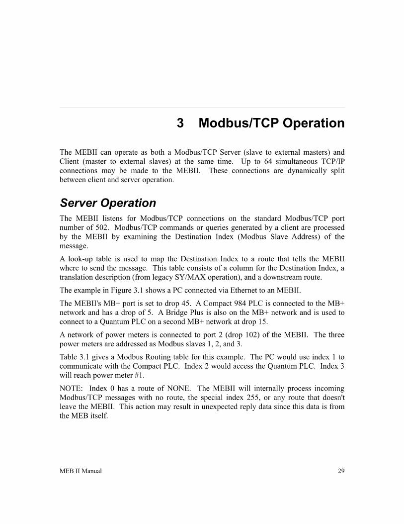
3 Modbus/TCP Operation
The MEBII can operate as both a Modbus/TCP Server (slave to external masters) and Client (master to external slaves) at the same time. Up to 64 simultaneous TCP/IP connections may be made to the MEBII. These connections are dynamically split between client and server operation.
Server OperationThe MEBII listens for Modbus/TCP connections on the standard Modbus/TCP port number of 502. Modbus/TCP commands or queries generated by a client are processed by the MEBII by examining the Destination Index (Modbus Slave Address) of the message.
A look-up table is used to map the Destination Index to a route that tells the MEBII where to send the message. This table consists of a column for the Destination Index, a translation description (from legacy SY/MAX operation), and a downstream route.
The example in Figure 3.1 shows a PC connected via Ethernet to an MEBII.
The MEBII's MB+ port is set to drop 45. A Compact 984 PLC is connected to the MB+ network and has a drop of 5. A Bridge Plus is also on the MB+ network and is used to connect to a Quantum PLC on a second MB+ network at drop 15.
A network of power meters is connected to port 2 (drop 102) of the MEBII. The three power meters are addressed as Modbus slaves 1, 2, and 3.
Table 3.1 gives a Modbus Routing table for this example. The PC would use index 1 to communicate with the Compact PLC. Index 2 would access the Quantum PLC. Index 3 will reach power meter #1.
NOTE: Index 0 has a route of NONE. The MEBII will internally process incoming Modbus/TCP messages with no route, the special index 255, or any route that doesn't leave the MEBII. This action may result in unexpected reply data since this data is from the MEB itself.
MEB II Manual 29
Table 3.1: Ethernet Modbus Routing Table Example
Index Type Route Comments
0 OTHER NONE MEBII Itself
1 MODBUS 45,5 Compact 984 PLC
2 MODBUS 45,6,15 Quantum PLC on far side of Bridge Plus
3 MODBUS 102,1 Power Meter 1
4 MODBUS 102,2 Power Meter 2
5 MODBUS 102,3 Power Meter 3
30 Modbus/TCP Operation 3 MEB II Manual
Figure 3.1 Ethernet Modbus Routing Example
Bridge Plus
MB+ 15
MB+ 5
MB+ 6
MB+ 45
MB 1MB 2MB 3
Drop 102
192.168.0.205
123456
7890
123456
7890
123456
7890
Default Modbus Routing Table
The default Modbus Routing table for the Ethernet port maps Modbus/TCP destination index values 1-64 to the MB+ node on the MEBII's MB+ network. Table entries 1 through 64 are set to have the first drop be the MB+ port number and the second drop be the same as the index for drops 1 through 64. Entries 65 through 96 use Port 1's drop number, 1 through 32. Entries 97 through 128 use Port 2's drop number, 1 though 32.
Table 3.2: Default Ethernet Modbus Routing Table for MB+ Drop 1, Port 1 drop 101, and Port 2 drop 102
Index Type Route
0 OTHER NONE
1 MODBUS 1,1
2 MODBUS 1,2
3 MODBUS 1,3
... MODBUS ...
63 MODBUS 1,63
64 MODBUS 1,64
65 MODBUS 101,1
66 MODBUS 101,2
67 MODBUS 101,3
68 MODBUS 101,4
... MODBUS ...
95 MODBUS 101,31
96 MODBUS 101,32
97 MODBUS 102,1
98 MODBUS 102,2
99 MODBUS 102,3
100 MODBUS 102,4
... MODBUS ...
127 MODBUS 102,31
128 MODBUS 102,32
129 OTHER NONE
MEB II Manual 3 Modbus/TCP Operation 31
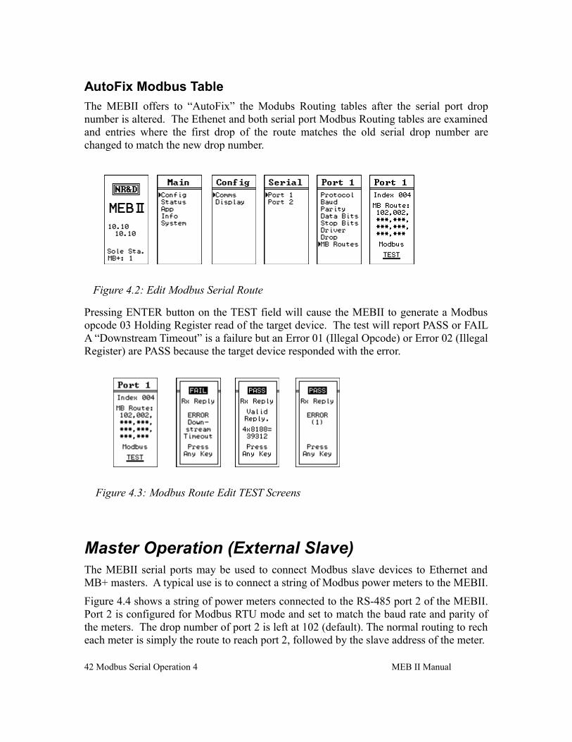
AutoFix Modbus Table
The MEBII offers to “AutoFix” the Modubs Routing tables after the MB+ drop number is altered. The Ethenet and both serial port Modbus Routing tables are examined and entries where the first drop of the route matches the old MB+ drop number are changed to match the new drop number.
32 Modbus/TCP Operation 3 MEB II Manual
Figure 3.2: Edit Modbus Plus Drop
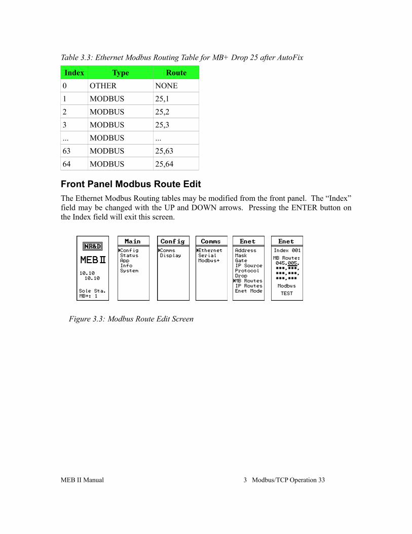
Table 3.3: Ethernet Modbus Routing Table for MB+ Drop 25 after AutoFix
Index Type Route
0 OTHER NONE
1 MODBUS 25,1
2 MODBUS 25,2
3 MODBUS 25,3
... MODBUS ...
63 MODBUS 25,63
64 MODBUS 25,64
Front Panel Modbus Route Edit
The Ethernet Modbus Routing tables may be modified from the front panel. The “Index” field may be changed with the UP and DOWN arrows. Pressing the ENTER button on the Index field will exit this screen.
MEB II Manual 3 Modbus/TCP Operation 33
Figure 3.3: Modbus Route Edit Screen
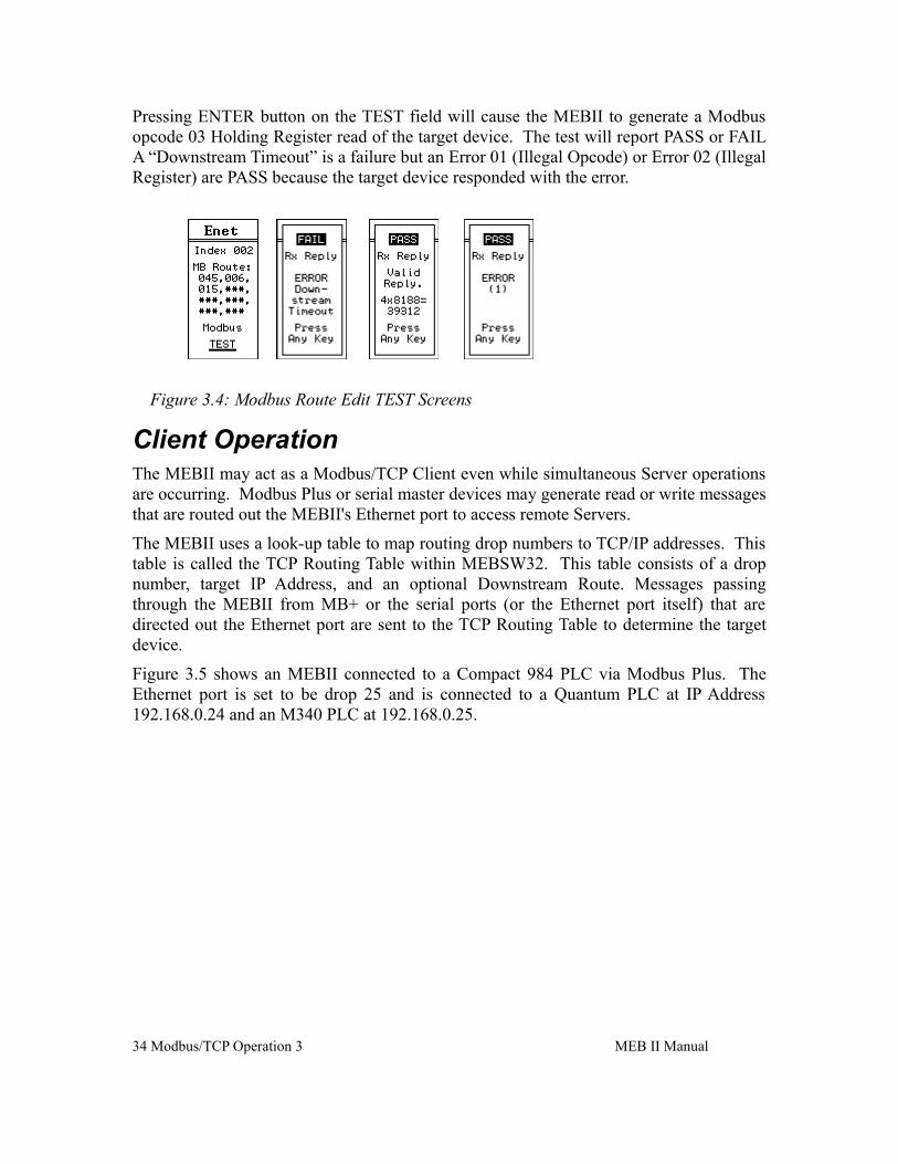
Pressing ENTER button on the TEST field will cause the MEBII to generate a Modbus opcode 03 Holding Register read of the target device. The test will report PASS or FAIL A “Downstream Timeout” is a failure but an Error 01 (Illegal Opcode) or Error 02 (Illegal Register) are PASS because the target device responded with the error.
Client OperationThe MEBII may act as a Modbus/TCP Client even while simultaneous Server operations are occurring. Modbus Plus or serial master devices may generate read or write messages that are routed out the MEBII's Ethernet port to access remote Servers.
The MEBII uses a look-up table to map routing drop numbers to TCP/IP addresses. This table is called the TCP Routing Table within MEBSW32. This table consists of a drop number, target IP Address, and an optional Downstream Route. Messages passing through the MEBII from MB+ or the serial ports (or the Ethernet port itself) that are directed out the Ethernet port are sent to the TCP Routing Table to determine the target device.
Figure 3.5 shows an MEBII connected to a Compact 984 PLC via Modbus Plus. The Ethernet port is set to be drop 25 and is connected to a Quantum PLC at IP Address 192.168.0.24 and an M340 PLC at 192.168.0.25.
34 Modbus/TCP Operation 3 MEB II Manual
Figure 3.4: Modbus Route Edit TEST Screens
Table 3.4: MEBII TCP Table Example
Drop IP Address Downstream Route
Comments
0 0.0.0.0 NONE
1 192.168.0.24 NONE Quantum PLC
2 192.168.0.25 NONE M340 PLC
3 192.168.0.205 NONE MEBII from Figure 3.1
4 0.0.0.0 NONE
MEB II Manual 3 Modbus/TCP Operation 35
Figure 3.5 Modbus Client Routing Example
MB+ 15
MB+ 21
M340Server
192.168.0.25
Quantum Server
192.168.0.24
192.168.0.241 Drop 0
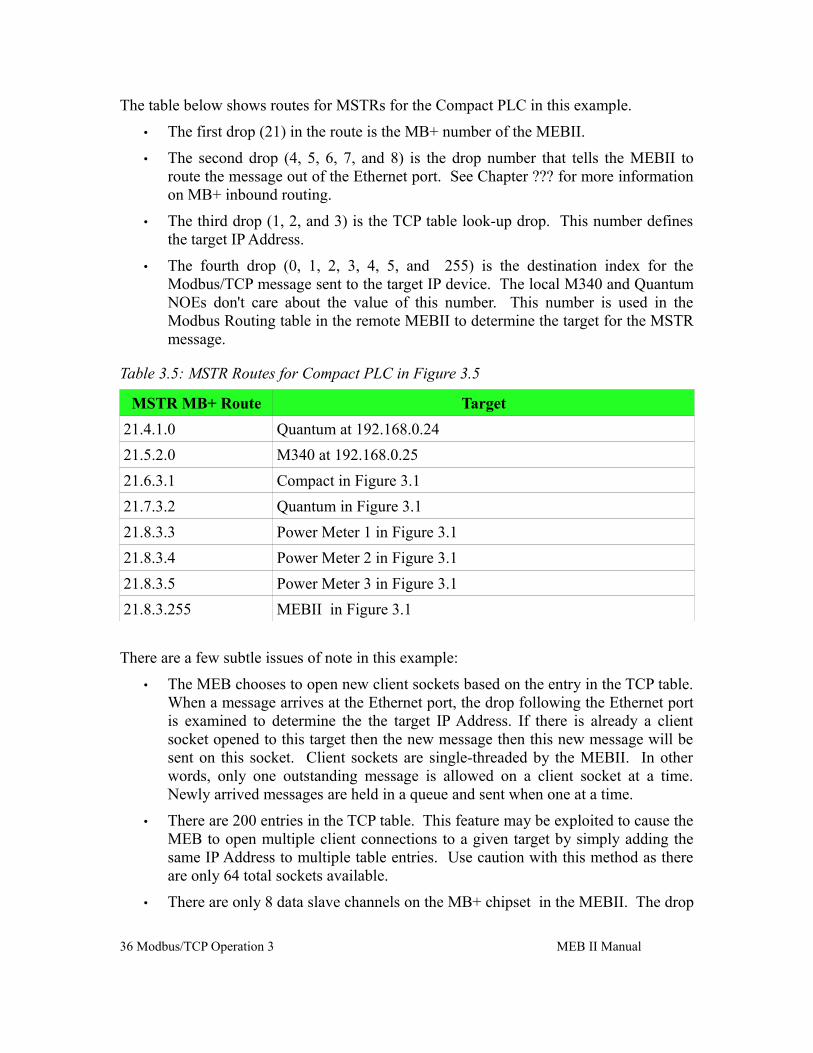
The table below shows routes for MSTRs for the Compact PLC in this example.
• The first drop (21) in the route is the MB+ number of the MEBII.
• The second drop (4, 5, 6, 7, and 8) is the drop number that tells the MEBII to route the message out of the Ethernet port. See Chapter ??? for more information on MB+ inbound routing.
• The third drop (1, 2, and 3) is the TCP table look-up drop. This number defines the target IP Address.
• The fourth drop (0, 1, 2, 3, 4, 5, and 255) is the destination index for the Modbus/TCP message sent to the target IP device. The local M340 and Quantum NOEs don't care about the value of this number. This number is used in the Modbus Routing table in the remote MEBII to determine the target for the MSTR message.
Table 3.5: MSTR Routes for Compact PLC in Figure 3.5
MSTR MB+ Route Target
21.4.1.0 Quantum at 192.168.0.24
21.5.2.0 M340 at 192.168.0.25
21.6.3.1 Compact in Figure 3.1
21.7.3.2 Quantum in Figure 3.1
21.8.3.3 Power Meter 1 in Figure 3.1
21.8.3.4 Power Meter 2 in Figure 3.1
21.8.3.5 Power Meter 3 in Figure 3.1
21.8.3.255 MEBII in Figure 3.1
There are a few subtle issues of note in this example:
• The MEB chooses to open new client sockets based on the entry in the TCP table. When a message arrives at the Ethernet port, the drop following the Ethernet port is examined to determine the the target IP Address. If there is already a client socket opened to this target then the new message then this new message will be sent on this socket. Client sockets are single-threaded by the MEBII. In other words, only one outstanding message is allowed on a client socket at a time. Newly arrived messages are held in a queue and sent when one at a time.
• There are 200 entries in the TCP table. This feature may be exploited to cause the MEB to open multiple client connections to a given target by simply adding the same IP Address to multiple table entries. Use caution with this method as there are only 64 total sockets available.
• There are only 8 data slave channels on the MB+ chipset in the MEBII. The drop
36 Modbus/TCP Operation 3 MEB II Manual
number following the MEB's MB+ drop number directly selects the data slave channel. (Channels 1 and 2 are dedicated to serial ports 1 and 2, channel 3 is dedicated to the MEB's internal registers, and channels 4, 5, 6, 7, and 8 are dedicated to the Ethernet port. MB+ data channels are single-threaded which means that only one message may be outstanding at a time on a given channel. If the PLC only has one MSTR active at a time, then the routes could be changed to only use a single data channel (like 4) with no impact on system throughput.
• Other PLCs on the same MB+ network could use exactly the same routes as this PLC. If multiple MB+ messages attempt to use the same data channel at the same time, the MB+ network takes care of this situation automatically, all of the messages get though, it just slows down a little as they take turns.
• The most efficient way to handle multiple PLCs generating client messages would be to partition data channels to each PLC/MSTR. (Don't configure 10 PLCs to only use a single data channel. It is more efficient to split them between the five possible channels.)
NOTE: When the MEBII's Ethernet port is in Modbus+SYMAX mode, the TCP table is how the unit decides to connect a client message via Modbus/TCP or SY/MAX 802.3. If the IP Address for a given drop number is 0.0.0.0 then the message is sent out as SY/MAX 802.3 to that drop number. See Chapter ???.
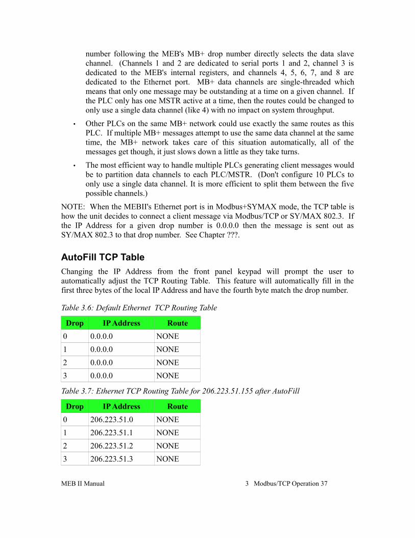
AutoFill TCP Table
Changing the IP Address from the front panel keypad will prompt the user to automatically adjust the TCP Routing Table. This feature will automatically fill in the first three bytes of the local IP Address and have the fourth byte match the drop number.
Table 3.6: Default Ethernet TCP Routing Table
Drop IP Address Route
0 0.0.0.0 NONE
1 0.0.0.0 NONE
2 0.0.0.0 NONE
3 0.0.0.0 NONE
Table 3.7: Ethernet TCP Routing Table for 206.223.51.155 after AutoFill
Drop IP Address Route
0 206.223.51.0 NONE
1 206.223.51.1 NONE
2 206.223.51.2 NONE
3 206.223.51.3 NONE
MEB II Manual 3 Modbus/TCP Operation 37
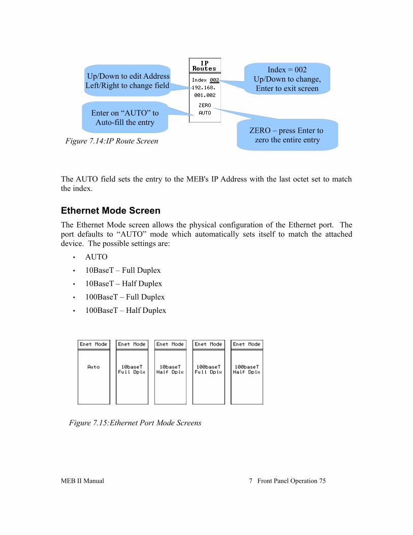
Front Panel Edit of TCP Table
The IP Routes may be edited from the front panel. The UP and DOWN buttons on the INDEX field scroll through the 200 entries. Pressing the ENTER button while on the INDEX field exits the screen.
Pressing the ENTER button while on the ZERO field will zero the IP Address. This is useful in SY/MAX Ethernet applications.
Pressing the ENTER button while on the AUTO field will auto load the AutoFill value for this Index.
38 Modbus/TCP Operation 3 MEB II Manual
Figure 3.6: IP Route Edit Screen
4 Modbus Serial Operation
The MEBII serial ports can operate as both a Modbus Master and Slave using either Modbus RTU and Modbus ASCII protocols. The protocol modes are labeled “Modbus RTU” and “Modbus ASCII”. All Modbus serial modes can dynamically switch between functioning as a Master or a Slave.
NOTE: The mode “MODBUS HOST” is a version of the RTU mode with special message translation features.
Slave Operation (External Master)A Modbus mode port on the MEBII listens for Modbus serial messages whenever it is idle. When a message arrives and has a good checksum, the Modbus Slave Address in the message is examined and compared to entries in the Modbus Routing Table for that serial port. If the entry for that drop number is not empty, then the MEBII will forward that message according to this defined route. If the entry is empty (NONE), then the message is ignored.
A look-up table is used to map the Destination Index to a route that tells the MEBII where to send the message. This table consists of a column for the Destination Index, a translation description (from legacy SY/MAX operation), and a downstream route.
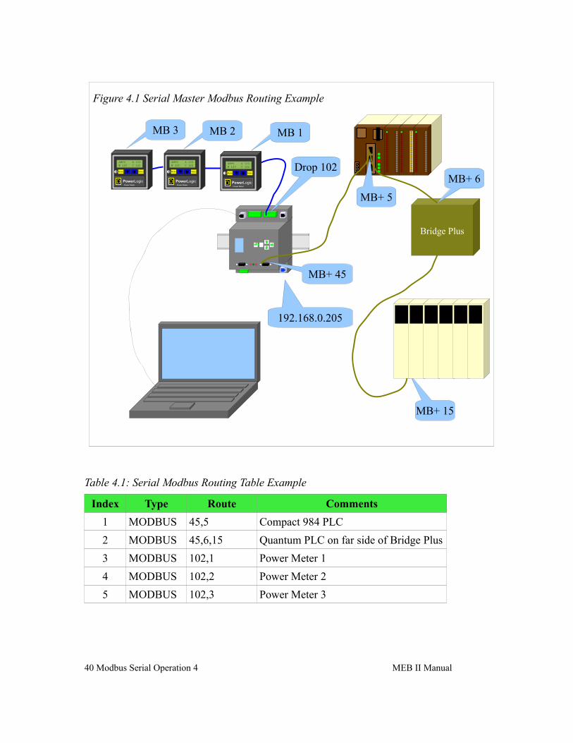
The example in Figure 4.1 shows a PC connected via RS-232 to an MEBII Port 1.
The MEBII's MB+ port is set to drop 45. A Compact 984 PLC is connected to the MB+ network and has a drop of 5. A Bridge Plus is also on the MB+ network and is used to connect to a Quantum PLC on a second MB+ network at drop 15.
A network of power meters is connected to port 2 (drop 102) of the MEBII. The three power meters are addressed as Modbus slaves 1, 2, and 3.
Table 4.1 gives a Modbus Routing table for this example. The PC would use index 1 to communicate with the Compact PLC. Index 2 would access the Quantum PLC. Index 3 will reach power meter #1.
NOTE: The MEBII will internally process incoming Modbus/TCP messages with the special index 255, or any route that doesn't leave the MEBII. This action may result in unexpected reply data since this data is from the MEB itself.
MEB II Manual 39
Table 4.1: Serial Modbus Routing Table Example
Index Type Route Comments
1 MODBUS 45,5 Compact 984 PLC
2 MODBUS 45,6,15 Quantum PLC on far side of Bridge Plus
3 MODBUS 102,1 Power Meter 1
4 MODBUS 102,2 Power Meter 2
5 MODBUS 102,3 Power Meter 3
40 Modbus Serial Operation 4 MEB II Manual
Figure 4.1 Serial Master Modbus Routing Example
Bridge Plus
MB+ 15
MB+ 5
MB+ 6
MB+ 45
MB 1MB 2MB 3
Drop 102
192.168.0.205
AMPS A 123B 125 C 122
Mode Select
PowerLogicPower Meter
D
AMPS A 123B 125 C 122
Mode Select
PowerLogicPower Meter
D
AMPS A 123B 125 C 122
Mode Select
PowerLogicPower Meter
D
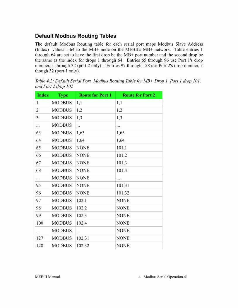
Default Modbus Routing Tables
The default Modbus Routing table for each serial port maps Modbus Slave Address (Index) values 1-64 to the MB+ node on the MEBII's MB+ network. Table entries 1 through 64 are set to have the first drop be the MB+ port number and the second drop be the same as the index for drops 1 through 64. Entries 65 through 96 use Port 1's drop number, 1 through 32 (port 2 only) . Entries 97 through 128 use Port 2's drop number, 1 though 32 (port 1 only).
Table 4.2: Default Serial Port Modbus Routing Table for MB+ Drop 1, Port 1 drop 101, and Port 2 drop 102
Index Type Route for Port 1 Route for Port 2
1 MODBUS 1,1 1,1
2 MODBUS 1,2 1,2
3 MODBUS 1,3 1,3
... MODBUS ... ...
63 MODBUS 1,63 1,63
64 MODBUS 1,64 1,64
65 MODBUS NONE 101,1
66 MODBUS NONE 101,2
67 MODBUS NONE 101,3
68 MODBUS NONE 101,4
... MODBUS NONE ...
95 MODBUS NONE 101,31
96 MODBUS NONE 101,32
97 MODBUS 102,1 NONE
98 MODBUS 102,2 NONE
99 MODBUS 102,3 NONE
100 MODBUS 102,4 NONE
... MODBUS ... NONE
127 MODBUS 102,31 NONE
128 MODBUS 102,32 NONE
MEB II Manual 4 Modbus Serial Operation 41
AutoFix Modbus Table
The MEBII offers to “AutoFix” the Modubs Routing tables after the serial port drop number is altered. The Ethenet and both serial port Modbus Routing tables are examined and entries where the first drop of the route matches the old serial drop number are changed to match the new drop number.
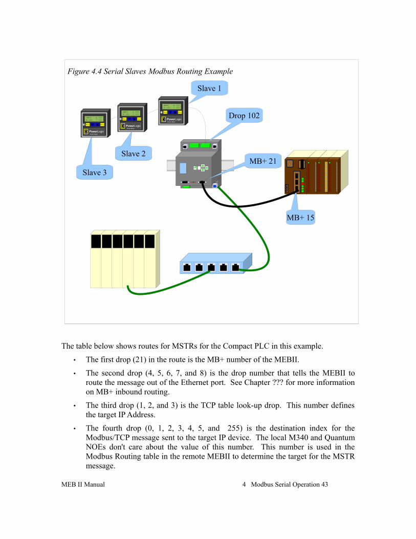
Pressing ENTER button on the TEST field will cause the MEBII to generate a Modbus opcode 03 Holding Register read of the target device. The test will report PASS or FAIL A “Downstream Timeout” is a failure but an Error 01 (Illegal Opcode) or Error 02 (Illegal Register) are PASS because the target device responded with the error.
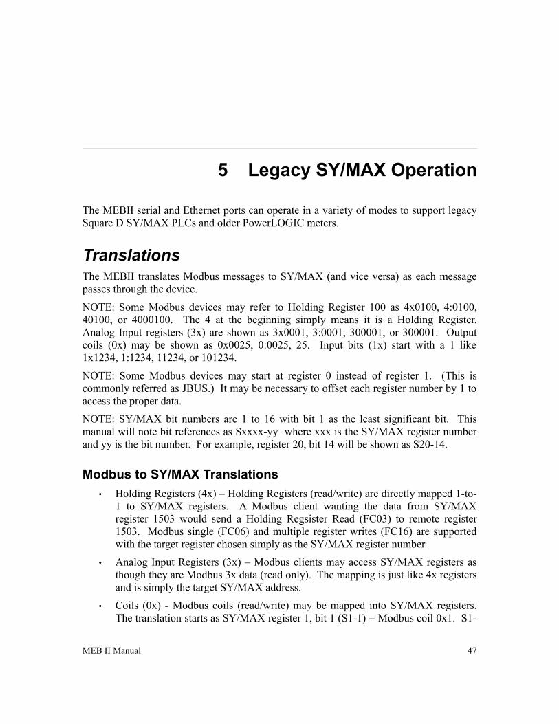
Master Operation (External Slave)The MEBII serial ports may be used to connect Modbus slave devices to Ethernet and MB+ masters. A typical use is to connect a string of Modbus power meters to the MEBII.
Figure 4.4 shows a string of power meters connected to the RS-485 port 2 of the MEBII. Port 2 is configured for Modbus RTU mode and set to match the baud rate and parity of the meters. The drop number of port 2 is left at 102 (default). The normal routing to rech each meter is simply the route to reach port 2, followed by the slave address of the meter.
42 Modbus Serial Operation 4 MEB II Manual
Figure 4.2: Edit Modbus Serial Route
Figure 4.3: Modbus Route Edit TEST Screens
The table below shows routes for MSTRs for the Compact PLC in this example.
• The first drop (21) in the route is the MB+ number of the MEBII.
• The second drop (4, 5, 6, 7, and 8) is the drop number that tells the MEBII to route the message out of the Ethernet port. See Chapter ??? for more information on MB+ inbound routing.
• The third drop (1, 2, and 3) is the TCP table look-up drop. This number defines the target IP Address.
• The fourth drop (0, 1, 2, 3, 4, 5, and 255) is the destination index for the Modbus/TCP message sent to the target IP device. The local M340 and Quantum NOEs don't care about the value of this number. This number is used in the Modbus Routing table in the remote MEBII to determine the target for the MSTR message.
MEB II Manual 4 Modbus Serial Operation 43
Figure 4.4 Serial Slaves Modbus Routing Example
MB+ 15
MB+ 21
Drop 102AMPS A 123B 125 C 122
Mode Select
PowerLogicPower Meter
D
AMPS A 123B 125 C 122
Mode Select
PowerLogicPower Meter
D
AMPS A 123B 125 C 122
Mode Select
PowerLogicPower Meter
D
Slave 1
Slave 2
Slave 3
Table 4.3: MSTR Routes for Compact PLC in Figure 4.4
MSTR MB+ Route Target
21.4.1.0 Quantum at 192.168.0.24
21.5.2.0 M340 at 192.168.0.25
21.6.3.1 Compact in Figure 4.1
21.7.3.2 Quantum in Figure 4.1
21.8.3.3 Power Meter 1 in Figure 4.1
21.8.3.4 Power Meter 2 in Figure 4.1
21.8.3.5 Power Meter 3 in Figure 4.1
21.8.3.255 MEBII in Figure 4.1
There are a few subtle issues of note in this example:
• The MEB chooses to open new client sockets based on the route to the Ethernet port. When a message arrives at the Ethernet port, the drop following the Ethernet port is examined to determine the the target IP Address. If the upstream portion of this route is the same as an already open client socket opened to this target then the new message then this new message will be sent on this socket. Client sockets are single-threaded by the MEBII. In other words, only one outstanding message is allowed on a client socket at a time. Newly arrived messages are held in a queue and sent when one at a time.
• There are 200 entries in the TCP table. This feature may be exploited to cause the MEB to open multiple client connections to a given target by simply adding the same IP Address to multiple table entries. Use caution with this method as there are only 64 total sockets available.
• There are only 8 data slave channels on the MB+ chipset in the MEBII. The drop number following the MEB's MB+ drop number directly selects the data slave channel. (Channels 1 and 2 are dedicated to serial ports 1 and 2, channel 3 is dedicated to the MEB's internal registers, and channels 4, 5, 6, 7, and 8 are dedicated to the Ethernet port. MB+ data channels are single-threaded which means that only one message may be outstanding at a time on a given channel. If the PLC only has one MSTR active at a time, then the routes could be changed to only use a single data channel (like 4) with no impact on system throughput.
• Other PLCs on the same MB+ network could use exactly the same routes as this PLC. If multiple MB+ messages attempt to use the same data channel at the same time, the MB+ network takes care of this situation automatically, all of the messages get though, it just slows down a little as they take turns.
44 Modbus Serial Operation 4 MEB II Manual
• The most efficient way to handle multiple PLCs generating client messages would be to partition data channels to each PLC/MSTR. (Don't configure 10 PLCs to only use a single data channel, split them up between the five possible channels.)
NOTE: When the MEBII's Ethernet port is in Modbus+SYMAX mode, the TCP table is how the unit decides to connect a client message via Modbus/TCP or SY/MAX 802.3. If the IP Address for a given drop number is 0.0.0.0 then the message is sent out as SY/MAX 802.3 to that drop number. See Chapter 5.
AutoFill TCP Table
Changing the IP Address from the front panel keypad will prompt the user to automatically adjust the TCP Routing Table. This feature will automatically fill in the first three bytes of the local IP Address and have the fourth byte match the drop number.
Table 4.4: Ethernet TCP Routing Table for Address 10.10.10.10
Drop IP Address Route
0 0.0.0.0 NONE
1 10.10.10.1 NONE
2 10.10.10.2 NONE
3 10.10.10.3 NONE
Table 4.5: Ethernet TCP Routing Table for 206.223.51.155 after AutoFill
Drop IP Address Route
0 0.0.0.0 NONE
1 206.223.51.1 NONE
2 206.223.51.2 NONE
3 206.223.51.3 NONE
MEB II Manual 4 Modbus Serial Operation 45
5 Legacy SY/MAX Operation
The MEBII serial and Ethernet ports can operate in a variety of modes to support legacy Square D SY/MAX PLCs and older PowerLOGIC meters.
TranslationsThe MEBII translates Modbus messages to SY/MAX (and vice versa) as each message passes through the device.
NOTE: Some Modbus devices may refer to Holding Register 100 as 4x0100, 4:0100, 40100, or 4000100. The 4 at the beginning simply means it is a Holding Register. Analog Input registers (3x) are shown as 3x0001, 3:0001, 300001, or 300001. Output coils (0x) may be shown as 0x0025, 0:0025, 25. Input bits (1x) start with a 1 like 1x1234, 1:1234, 11234, or 101234.
NOTE: Some Modbus devices may start at register 0 instead of register 1. (This is commonly referred as JBUS.) It may be necessary to offset each register number by 1 to access the proper data.
NOTE: SY/MAX bit numbers are 1 to 16 with bit 1 as the least significant bit. This manual will note bit references as Sxxxx-yy where xxx is the SY/MAX register number and yy is the bit number. For example, register 20, bit 14 will be shown as S20-14.
Modbus to SY/MAX Translations
• Holding Registers (4x) – Holding Registers (read/write) are directly mapped 1-to-1 to SY/MAX registers. A Modbus client wanting the data from SY/MAX register 1503 would send a Holding Regsister Read (FC03) to remote register 1503. Modbus single (FC06) and multiple register writes (FC16) are supported with the target register chosen simply as the SY/MAX register number.
• Analog Input Registers (3x) – Modbus clients may access SY/MAX registers as though they are Modbus 3x data (read only). The mapping is just like 4x registers and is simply the target SY/MAX address.
• Coils (0x) - Modbus coils (read/write) may be mapped into SY/MAX registers. The translation starts as SY/MAX register 1, bit 1 (S1-1) = Modbus coil 0x1. S1-
MEB II Manual 47
16 = 0x16. S2-1 = 0x17. The formula to determine the Modbus coil from a SY/MAX bit is: COIL = ((REG – 1) * 16) + (BIT).
• Input Bits (1x) – Modbus discrete inputs (read only) are mapped exactly the same as 0x coils.
Incoming Modbus commands (4x, 3x, 1x, 0x) are translated into Non-Priority SY/MAX Read or Write messages. Coil write messages (FC05 and FC15) are translated as bit-masked NP writes when possible to allow single SY/MAX bits to be modified.
NOTE: FC15 multiple coil write message may not be able to be processed when the bits span multiple SY/MAX registers. The SY/MAX bit-masked NP Write message cannot handle this type of masking operation. The MEBII will send back a Modbus Exception code 5 error when this condition occurs.
NOTE: A few SY/MAX end devices (NIMs for example) do not support Non-Priority messages. It may not be possible for a Modbus client to be able to directly communicate with these devices.
SY/MAX to Modbus Translations
SY/MAX Priority and Non-Priority Read and Write command messages are translated into Holding Register Read (FC03) and Write (FC16) messages. SY/MAX Random Access Read messages are translated into PowerLOGIC's Modbus Random Access Read (FC100).
If the SY/MAX client needs to access other memory spaces on a Modbus serial server, the Modbus Host serial mode may be used. This mode allows the user to manually configure the translation for both the read and the write. Supported Modbus Function Codes are 03 (4x read), 04 (3x read), 02 (1x read), 01 (0x read), 05 (0x single write), 06 (4x single write), 15 (0x multiple write), and 16 (4x multiple write).
NOTE: Standard Priority and non-bit-maksed Non-Priority SY/MAX write messages will translate into 16 FC05 coil messages or one 16-bit FC15 message. All 16 bits will be forced.
NOTE: SY/MAX Read and Write messages support up to 128 registers. Modbus messages are limited to a maximum of 125 registers on a read and 120 registers on a write. Individual servers may have additional register count restrictions.
Error Translations
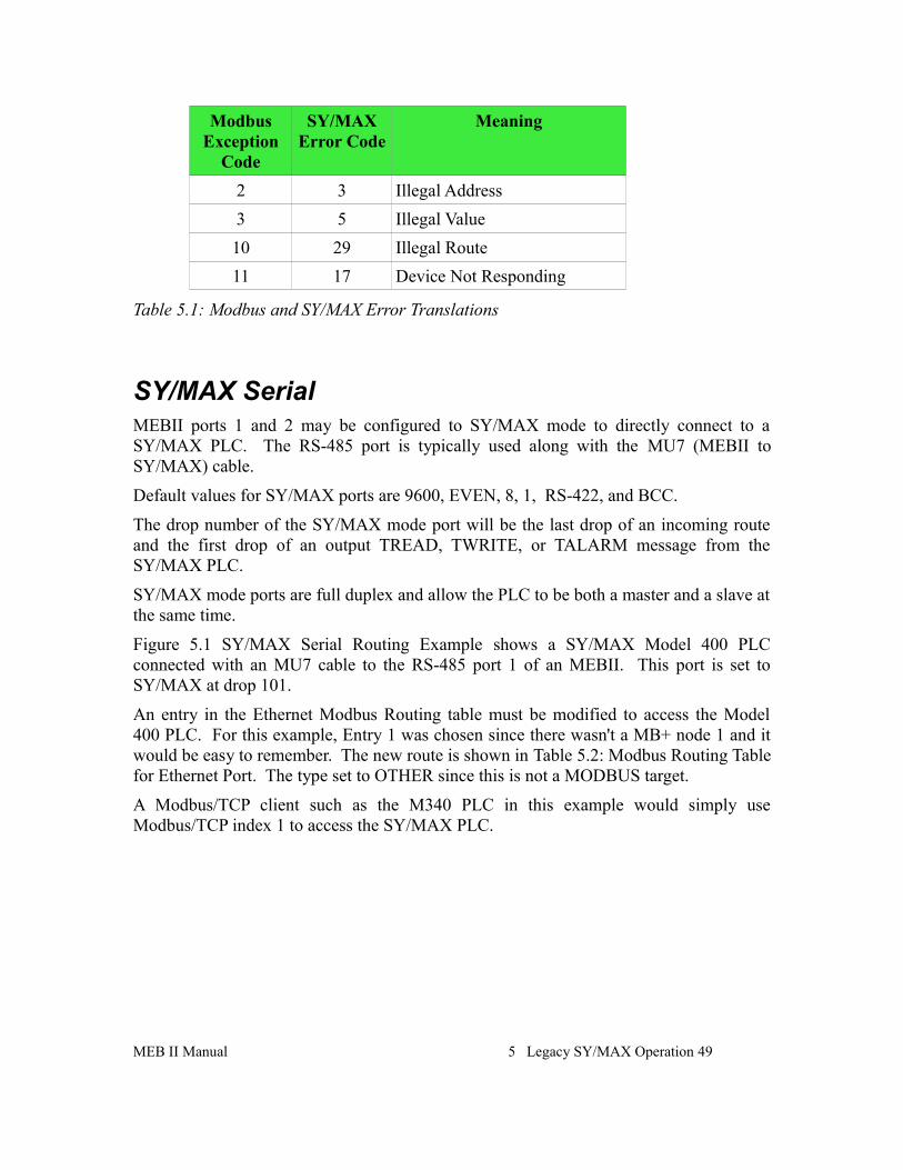
Modbus and SY/MAX do not share the same error messages. Table 5.1 shows the MEBII's translations.
All other errors are passed straight through with no translation.
48 Legacy SY/MAX Operation 5 MEB II Manual
Modbus Exception
Code
SY/MAX Error Code
Meaning
2 3 Illegal Address
3 5 Illegal Value
10 29 Illegal Route
11 17 Device Not Responding
Table 5.1: Modbus and SY/MAX Error Translations
SY/MAX SerialMEBII ports 1 and 2 may be configured to SY/MAX mode to directly connect to a SY/MAX PLC. The RS-485 port is typically used along with the MU7 (MEBII toSY/MAX) cable.
Default values for SY/MAX ports are 9600, EVEN, 8, 1, RS-422, and BCC.
The drop number of the SY/MAX mode port will be the last drop of an incoming route and the first drop of an output TREAD, TWRITE, or TALARM message from the SY/MAX PLC.
SY/MAX mode ports are full duplex and allow the PLC to be both a master and a slave at the same time.
Figure 5.1 SY/MAX Serial Routing Example shows a SY/MAX Model 400 PLC connected with an MU7 cable to the RS-485 port 1 of an MEBII. This port is set to SY/MAX at drop 101.
An entry in the Ethernet Modbus Routing table must be modified to access the Model 400 PLC. For this example, Entry 1 was chosen since there wasn't a MB+ node 1 and it would be easy to remember. The new route is shown in Table 5.2: Modbus Routing Tablefor Ethernet Port. The type set to OTHER since this is not a MODBUS target.
A Modbus/TCP client such as the M340 PLC in this example would simply use Modbus/TCP index 1 to access the SY/MAX PLC.
MEB II Manual 5 Legacy SY/MAX Operation 49
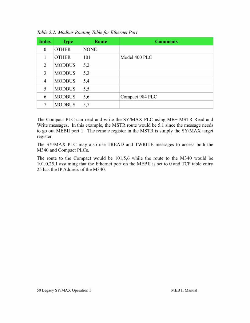
Table 5.2: Modbus Routing Table for Ethernet Port
Index Type Route Comments
0 OTHER NONE
1 OTHER 101 Model 400 PLC
2 MODBUS 5,2
3 MODBUS 5,3
4 MODBUS 5,4
5 MODBUS 5,5
6 MODBUS 5,6 Compact 984 PLC
7 MODBUS 5,7
The Compact PLC can read and write the SY/MAX PLC using MB+ MSTR Read and Write messages. In this example, the MSTR route would be 5.1 since the message needs to go out MEBII port 1. The remote register in the MSTR is simply the SY/MAX target register.
The SY/MAX PLC may also use TREAD and TWRITE messages to access both the M340 and Compact PLCs.
The route to the Compact would be 101,5,6 while the route to the M340 would be 101,0,25,1 assuming that the Ethernet port on the MEBII is set to 0 and TCP table entry 25 has the IP Address of the M340.
50 Legacy SY/MAX Operation 5 MEB II Manual
NET-TO-NET Mode
The MEBII may be connected to a SY/NET network using the NET-TO-NET mode. This mode is used to connect the MEBII to an RS-422 port on a CRM-510 NIM, RS-422 port on a SY/LINK (SFI-510) PC card, Niobrara SPE4, EPE5, or even MEB modules.
The following rules apply to NET-TO-NET ports:
• Both ports must be set to NET-TO-NET mode. This may involve setting DIP switches on the NIM.
• Both ports must be set to the same SY/NET drop number. Set the MEBII port to match the NIM.
• Both ports must have the same baud rate, parity, data bits, stop bits, and
MEB II Manual 5 Legacy SY/MAX Operation 51
Figure 5.1 SY/MAX Serial Routing Example
MB+ 6
192.168.0.25
192.168.0.241
Drop 101 MB+ 5MU7 Cable
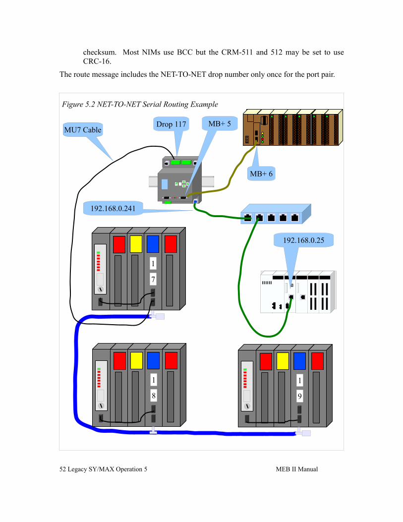
checksum. Most NIMs use BCC but the CRM-511 and 512 may be set to use CRC-16.
The route message includes the NET-TO-NET drop number only once for the port pair.
52 Legacy SY/MAX Operation 5 MEB II Manual
Figure 5.2 NET-TO-NET Serial Routing Example
MB+ 6
192.168.0.25
192.168.0.241
Drop 117 MB+ 5MU7 Cable
1
9
1
8
1
7
Figure 5.2 NET-TO-NET Serial Routing Example show an MEBII port 1 connected NET-TO-NET to a CRM-510 set to node 17. This NIM is on a small “Blue Hose” SY/NET with two other NIMs set to 18 and 19. NIMs 17 and 18 have a PLC connected to the 0xx port with a CC-100 cable. NIM 19 has the PLC connected to port 119. The MEBII is connected to the 117 port so the drop number of the MEBII port 1 must also be set to 117. Both the NIM port and MEBII must be set to NET-TO-NET mode.
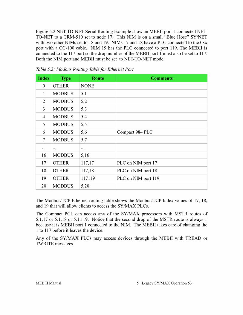
Table 5.3: Modbus Routing Table for Ethernet Port
Index Type Route Comments
0 OTHER NONE
1 MODBUS 5,1
2 MODBUS 5,2
3 MODBUS 5,3
4 MODBUS 5,4
5 MODBUS 5,5
6 MODBUS 5,6 Compact 984 PLC
7 MODBUS 5,7
... ... ...
16 MODBUS 5,16
17 OTHER 117,17 PLC on NIM port 17
18 OTHER 117,18 PLC on NIM port 18
19 OTHER 117119 PLC on NIM port 119
20 MODBUS 5,20
The Modbus/TCP Ethernet routing table shows the Modbus/TCP Index values of 17, 18, and 19 that will allow clients to access the SY/MAX PLCs.
The Compact PCL can access any of the SY/MAX processors with MSTR routes of 5.1.17 or 5.1.18 or 5.1.119. Notice that the second drop of the MSTR route is always 1 because it is MEBII port 1 connected to the NIM. The MEBII takes care of changing the 1 to 117 before it leaves the device.
Any of the SY/MAX PLCs may access devices through the MEBII with TREAD or TWRITE messages.
MEB II Manual 5 Legacy SY/MAX Operation 53
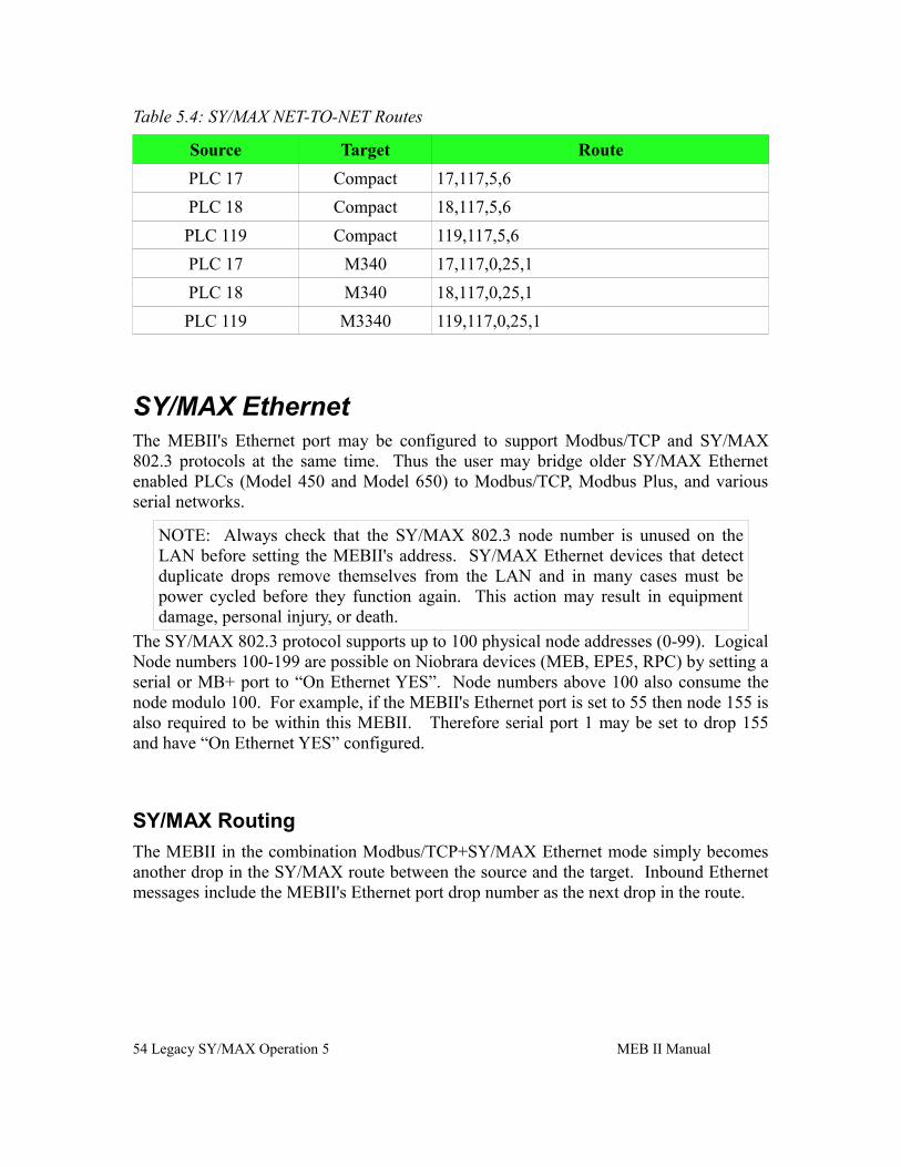
Table 5.4: SY/MAX NET-TO-NET Routes
Source Target Route
PLC 17 Compact 17,117,5,6
PLC 18 Compact 18,117,5,6
PLC 119 Compact 119,117,5,6
PLC 17 M340 17,117,0,25,1
PLC 18 M340 18,117,0,25,1
PLC 119 M3340 119,117,0,25,1
SY/MAX EthernetThe MEBII's Ethernet port may be configured to support Modbus/TCP and SY/MAX 802.3 protocols at the same time. Thus the user may bridge older SY/MAX Ethernet enabled PLCs (Model 450 and Model 650) to Modbus/TCP, Modbus Plus, and various serial networks.
NOTE: Always check that the SY/MAX 802.3 node number is unused on the LAN before setting the MEBII's address. SY/MAX Ethernet devices that detect duplicate drops remove themselves from the LAN and in many cases must be power cycled before they function again. This action may result in equipment damage, personal injury, or death.
The SY/MAX 802.3 protocol supports up to 100 physical node addresses (0-99). Logical Node numbers 100-199 are possible on Niobrara devices (MEB, EPE5, RPC) by setting a serial or MB+ port to “On Ethernet YES”. Node numbers above 100 also consume the node modulo 100. For example, if the MEBII's Ethernet port is set to 55 then node 155 is also required to be within this MEBII. Therefore serial port 1 may be set to drop 155 and have “On Ethernet YES” configured.
SY/MAX Routing
The MEBII in the combination Modbus/TCP+SY/MAX Ethernet mode simply becomes another drop in the SY/MAX route between the source and the target. Inbound Ethernet messages include the MEBII's Ethernet port drop number as the next drop in the route.
54 Legacy SY/MAX Operation 5 MEB II Manual
MEB II Manual 5 Legacy SY/MAX Operation 55
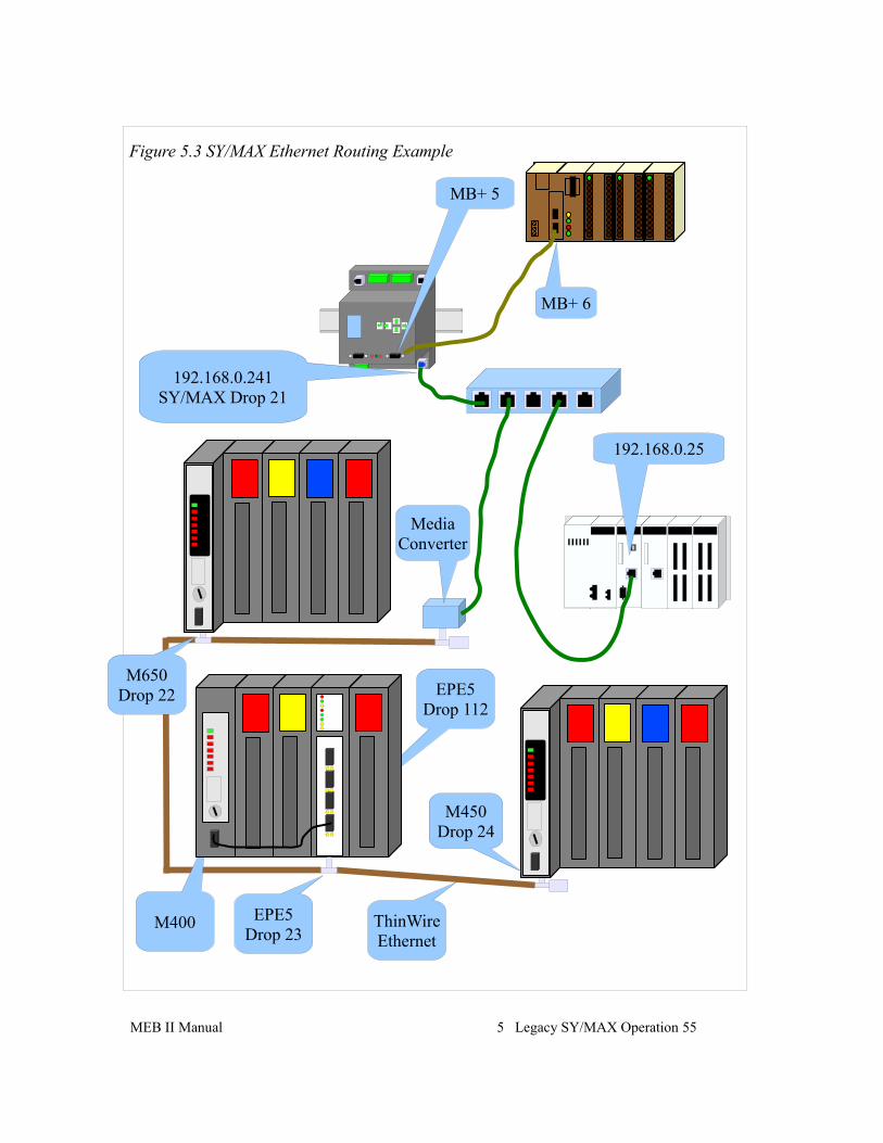
Figure 5.3 SY/MAX Ethernet Routing Example
MB+ 6
192.168.0.25
192.168.0.241SY/MAX Drop 21
MB+ 5
M450Drop 24
EPE5Drop 112
EPE5Drop 23
M650Drop 22
MediaConverter
ThinWireEthernet
M400
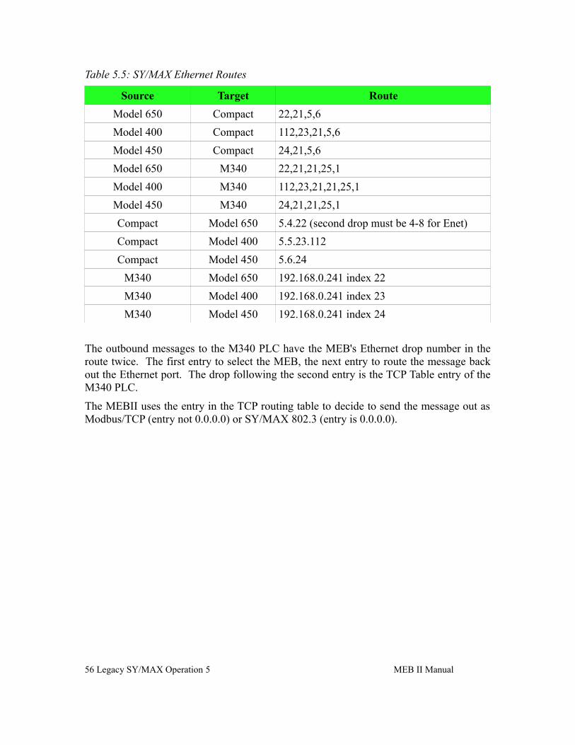
Table 5.5: SY/MAX Ethernet Routes
Source Target Route
Model 650 Compact 22,21,5,6
Model 400 Compact 112,23,21,5,6
Model 450 Compact 24,21,5,6
Model 650 M340 22,21,21,25,1
Model 400 M340 112,23,21,21,25,1
Model 450 M340 24,21,21,25,1
Compact Model 650 5.4.22 (second drop must be 4-8 for Enet)
Compact Model 400 5.5.23.112
Compact Model 450 5.6.24
M340 Model 650 192.168.0.241 index 22
M340 Model 400 192.168.0.241 index 23
M340 Model 450 192.168.0.241 index 24
The outbound messages to the M340 PLC have the MEB's Ethernet drop number in the route twice. The first entry to select the MEB, the next entry to route the message back out the Ethernet port. The drop following the second entry is the TCP Table entry of the M340 PLC.
The MEBII uses the entry in the TCP routing table to decide to send the message out as Modbus/TCP (entry not 0.0.0.0) or SY/MAX 802.3 (entry is 0.0.0.0).
56 Legacy SY/MAX Operation 5 MEB II Manual
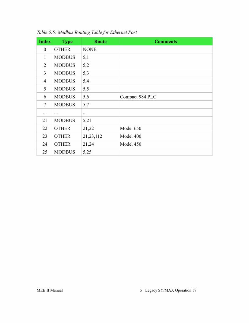
Table 5.6: Modbus Routing Table for Ethernet Port
Index Type Route Comments
0 OTHER NONE
1 MODBUS 5,1
2 MODBUS 5,2
3 MODBUS 5,3
4 MODBUS 5,4
5 MODBUS 5,5
6 MODBUS 5,6 Compact 984 PLC
7 MODBUS 5,7
... ... ...
21 MODBUS 5,21
22 OTHER 21,22 Model 650
23 OTHER 21,23,112 Model 400
24 OTHER 21,24 Model 450
25 MODBUS 5,25
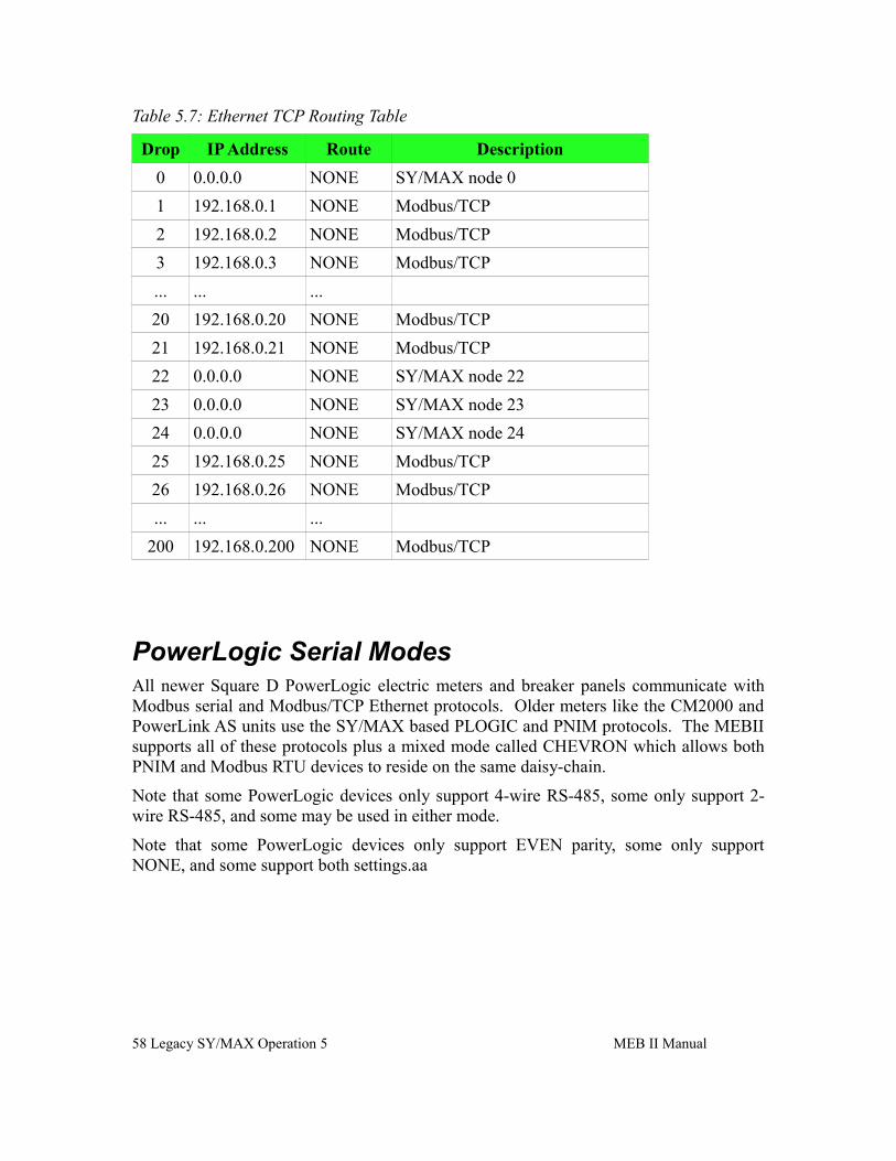
MEB II Manual 5 Legacy SY/MAX Operation 57
Table 5.7: Ethernet TCP Routing Table
Drop IP Address Route Description
0 0.0.0.0 NONE SY/MAX node 0
1 192.168.0.1 NONE Modbus/TCP
2 192.168.0.2 NONE Modbus/TCP
3 192.168.0.3 NONE Modbus/TCP
... ... ...
20 192.168.0.20 NONE Modbus/TCP
21 192.168.0.21 NONE Modbus/TCP
22 0.0.0.0 NONE SY/MAX node 22
23 0.0.0.0 NONE SY/MAX node 23
24 0.0.0.0 NONE SY/MAX node 24
25 192.168.0.25 NONE Modbus/TCP
26 192.168.0.26 NONE Modbus/TCP
... ... ...
200 192.168.0.200 NONE Modbus/TCP
PowerLogic Serial ModesAll newer Square D PowerLogic electric meters and breaker panels communicate with Modbus serial and Modbus/TCP Ethernet protocols. Older meters like the CM2000 and PowerLink AS units use the SY/MAX based PLOGIC and PNIM protocols. The MEBII supports all of these protocols plus a mixed mode called CHEVRON which allows both PNIM and Modbus RTU devices to reside on the same daisy-chain.
Note that some PowerLogic devices only support 4-wire RS-485, some only support 2-wire RS-485, and some may be used in either mode.
Note that some PowerLogic devices only support EVEN parity, some only support NONE, and some support both settings.aa
58 Legacy SY/MAX Operation 5 MEB II Manual
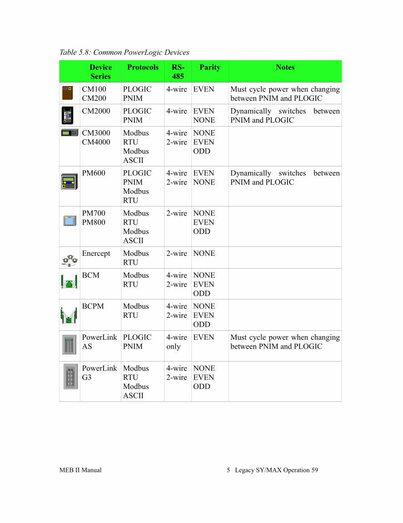
Table 5.8: Common PowerLogic Devices
Device Series
Protocols RS-485
Parity Notes
CM100CM200
PLOGIC PNIM
4-wire EVEN Must cycle power when changing between PNIM and PLOGIC
CM2000 PLOGICPNIM
4-wire EVENNONE
Dynamically switches between PNIM and PLOGIC
CM3000CM4000
Modbus RTUModbus ASCII
4-wire2-wire
NONEEVENODD
PM600 PLOGIC PNIM Modbus RTU
4-wire 2-wire
EVENNONE
Dynamically switches between PNIM and PLOGIC
PM700PM800
Modbus RTUModbus ASCII
2-wire NONEEVENODD
Enercept Modbus RTU
2-wire NONE
BCM Modbus RTU
4-wire 2-wire
NONEEVENODD
BCPM Modbus RTU
4-wire 2-wire
NONEEVENODD
PowerLink AS
PLOGICPNIM
4-wire only
EVEN Must cycle power when changing between PNIM and PLOGIC
PowerLink G3
Modbus RTUModbus ASCII
4-wire 2-wire
NONEEVENODD
MEB II Manual 5 Legacy SY/MAX Operation 59
6 Hot MB+ Operation
Automatic Redundant OperationThe MEBII features a unique operating mode called “Hot MB+” that allows two MEBII units to operate in a fully redundant, hot-backup system. One MEBII acts as the “Primary” unit performing the typical serial, Ethernet, and Modbus Plus message routing and translations, while the “Secondary” unit monitors the Primary and waits for its chance to take over should something fail (power supply, Ethernet link, or Modbus Plus connection). When a changeover event occurs, the Secondary unit becomes the new Primary and assumes it's IP Address and MB+ node number, and all routing information.
Both units are configured exactly the same and online configuration changes are only allowed on the Primary. The Secondary unit monitors the EEPROM configuration of the Primary and if the two units are not configured exactly the same, the Secondary automatically pulls the entire configuration from the Primary.
Requirements and Restrictions
• Port 2 of both MEBIIs are required to be be connected together with either 4-wire RS-422 or RS-232 cables. This serial connection is required for automatic configuration transfers when the Primary and Secondary miss-match. This connection must be full-duplex 4-wire RS-422 or RS-232. 2-wire RS-485 is not permitted.
• The Primary and Secondary units require adjacent TCP/IP Addresses. For example, if the Primary is at address 192.168.5.178, the Secondary will be at address 192.168.5.179.
• The Primary and Secondary units require adjacent MB+ drop numbers. For example, if the Primary is at node 53, the Secondary will be at node 54.
• Online modifications of the configuration are only allowed in the Primary unit. The Secondary unit is effectively “read-only”. The Secondary unit only allows “USER” web access (not “ADMIN”).
• Modifications made in the Primary are only updated in the Secondary after a “Store to EEPROM” operation has occurred. Future “Store to EEPROM” operations are temporarily locked out while the Secondary is fetching the new configuration.
• The transition from Secondary to Primary is not “bumpless”. It takes about 16 seconds for the Modbus Plus chipset to restart to the Primary's address.
• SY/MAX 802.3 Ethernet operation is not supported in Hot MB+ mode at this time.
60 Hot MB+ Operation 6 MEB II Manual
• Modbus serial slave and RNIM slave operation on Port 1 are not supported at this time.
• Modbus serial master, Chevron mode, PNIM, and RNIM master operations on port 1 are supported in RS-485 driver modes allowing redundant access of serial slaves from both Modbus Plus and Ethernet.
• Any PLC programming connection active through the Primary will close during a transfer from Secondary to Primary.
• It is recommended that each MEBII have it's own power supply and Ethernet connection to an independent switch to avoid any singly point of failure.
• MB+ Global Data is used between the Primary and Secondary MEBIIs and is not available for general mailbox use. The Global Data may be used by other MB+ devices to see the state and serial numbers of both Primary and Secondary units.
“Primary” Unit Configuration Procedure
1. Mount one of the MEBII units on a DIN rail. This unit will be the “Primary”.
2. Do not connect any serial, Ethernet, or MB+ cables at this time.
3. Apply power to this unit.
4. It is recommended to perform a Factory Reset on the unit at this time. Select “System”, “Factory”, “Defaults” to reset the unit to a known state.
5. Configure this unit with the Primary IP Address, Modbus Plus drop number, Modbus routing tables, IP tables, and serial port 1 parameters. This configuration may be done through the front panel LCD/keypad and/or web server. Be certain to store the configuration to EEPROM.
6. Connect the Ethernet and MB+ cables to the Primary unit.
7. Test the routing and the rest of the configuration to be sure that everything is operating correctly.
8. If configuring through the front panel:
Select “System”, “Hot MB+”, “Init Prim”. This changes the system operation to Hot MB+ mode and takes control of Port 2 for Hot MB+ interconnection.
If configuring through the web server:
Select “Config”, “Port 2”, and change the mode to “Hot MB+”. Now select “Init Primary” then “Store EEPROM”.
The “Primary” unit is now fully functional.
MEB II Manual 6 Hot MB+ Operation 61
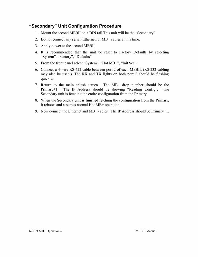
“Secondary” Unit Configuration Procedure
1. Mount the second MEBII on a DIN rail This unit will be the “Secondary”.
2. Do not connect any serial, Ethernet, or MB+ cables at this time.
3. Apply power to the second MEBII.
4. It is recommended that the unit be reset to Factory Defaults by selecting “System”, “Factory”, “Defaults”.
5. From the front panel select “System”, “Hot MB+”, “Init Sec”.
6. Connect a 4-wire RS-422 cable between port 2 of each MEBII. (RS-232 cabling may also be used.). The RX and TX lights on both port 2 should be flashing quickly.
7. Return to the main splash screen. The MB+ drop number should be the Primary+1. The IP Address should be showing “Reading Config”. The Secondary unit is fetching the entire configuration from the Primary.
8. When the Secondary unit is finished fetching the configuration from the Primary, it reboots and assumes normal Hot MB+ operation.
9. Now connect the Ethernet and MB+ cables. The IP Address should be Primary+1.
62 Hot MB+ Operation 6 MEB II Manual
Example
MEB II Manual 6 Hot MB+ Operation 63
Figure 6.1 Hot MB+ Example
To MB+ Network
Port 2 4-wire RS-422
Cable
Reasons for Automatic Switchover• Primary becomes sole station on MB+.
• Primary looses Ethernet link. Both Ethernet ports must loose link on an MEBII+201 for a switchover to occur.
• “Revert to Secondary” command written to Primary via Modbus communication.
• Secondary unit will become Primary if Primary MB+ Global Data is not present and port 2 communications are lost. For example, power is removed from the Primary.
• Firmware update is completed on Primary unit.
• Unequal Firmware in the two units will cause the unit with the oldest firmware to become the Primary. This will allow the oldest unit to have its firmware to be updated because only the Primary unit may have its firmware upgraded through the web page.
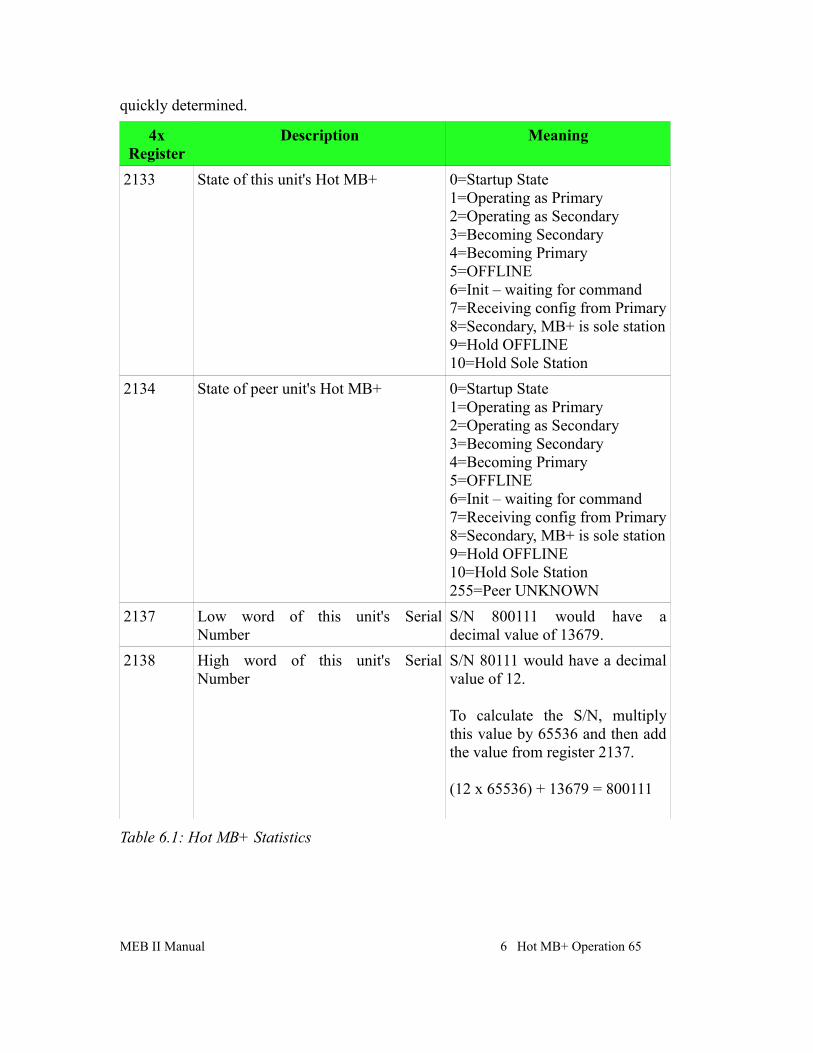
Hot MB+ Statistics and Information RegistersThe Hot MB+ mode uses a number of the standard Port 2 statistical counters with new meanings. Of particular interest are the State values in registers 2133 and 2134 and the MEB's serial number in registers 2137 and 2138.
It may be desirable to have an HMI periodically poll the Primary MEBII to read the state of the Primary and Secondary units. The serial number of the primary unit may also be
64 Hot MB+ Operation 6 MEB II Manual
Figure 6.2 Hot MB+ Port 2 RS-422 Cable
quickly determined.
4x Register
Description Meaning
2133 State of this unit's Hot MB+ 0=Startup State1=Operating as Primary2=Operating as Secondary3=Becoming Secondary4=Becoming Primary5=OFFLINE6=Init – waiting for command7=Receiving config from Primary8=Secondary, MB+ is sole station9=Hold OFFLINE10=Hold Sole Station
2134 State of peer unit's Hot MB+ 0=Startup State1=Operating as Primary2=Operating as Secondary3=Becoming Secondary4=Becoming Primary5=OFFLINE6=Init – waiting for command7=Receiving config from Primary8=Secondary, MB+ is sole station9=Hold OFFLINE10=Hold Sole Station255=Peer UNKNOWN
2137 Low word of this unit's Serial Number
S/N 800111 would have a decimal value of 13679.
2138 High word of this unit's Serial Number
S/N 80111 would have a decimal value of 12.
To calculate the S/N, multiply this value by 65536 and then add the value from register 2137.
(12 x 65536) + 13679 = 800111
Table 6.1: Hot MB+ Statistics
MEB II Manual 6 Hot MB+ Operation 65
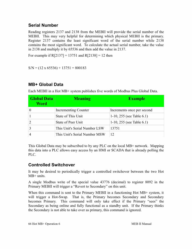
Serial Number
Reading registers 2137 and 2138 from the MEBII will provide the serial number of the MEBII. This may very helpful for determining which physical MEBII is the primary. Register 2137 contains the least significant word of the serial number while 2138 contains the most significant word. To calculate the actual serial number, take the value in 2138 and multiply it by 65536 and then add the value in 2137.
For example if R[2137] = 13751 and R[2138] = 12 then
S/N = (12 x 65536) + 13751 = 800183
MB+ Global Data
Each MEBII in a Hot MB+ system publishes five words of Modbus Plus Global Data.
Global Data Word
Meaning Example
0 Incrementing Counter Increments once per second
1 State of This Unit 1-10, 255 (see Table 6.1)
2 State of Peer Unit 1-10, 255 (see Table 6.1)
3 This Unit's Serial Number LSW 13751
4 This Unit's Serial Number MSW 12
This Global Data may be subscribed to by any PLC on the local MB+ network. Mapping this data into a PLC allows easy access by an HMI or SCADA that is already polling the PLC.
Controlled Switchover
It may be desired to periodically trigger a controlled switchover between the two Hot MB+ units.
A single Modbus write of the special value 43776 (decimal) to register 8092 in the Primary MEBII will trigger a “Revert to Secondary” on this unit.
When this command is sent to the Primary MEBII in a functioning Hot MB+ system, it will trigger a Hot-Swap. That is, the Primary becomes Secondary and Secondary becomes Primary. This command will only take effect if the Primary “sees” the Secondary as being online and fully functional as a standby unit. If the Primary thinks the Secondary is not able to take over as primary, this command is ignored.
66 Hot MB+ Operation 6 MEB II Manual
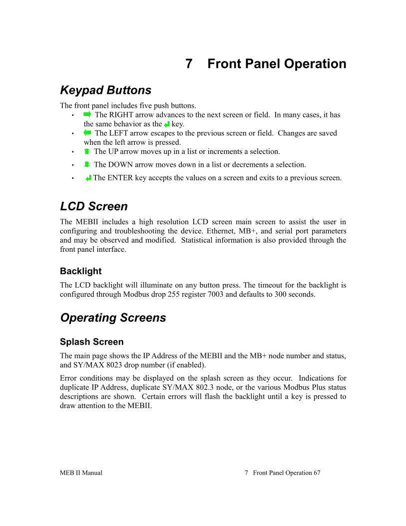
7 Front Panel Operation
Keypad ButtonsThe front panel includes five push buttons.
• The RIGHT arrow advances to the next screen or field. In many cases, it has the same behavior as the key.
• The LEFT arrow escapes to the previous screen or field. Changes are saved when the left arrow is pressed.
• The UP arrow moves up in a list or increments a selection.
• The DOWN arrow moves down in a list or decrements a selection.
• The ENTER key accepts the values on a screen and exits to a previous screen.
LCD ScreenThe MEBII includes a high resolution LCD screen main screen to assist the user in configuring and troubleshooting the device. Ethernet, MB+, and serial port parameters and may be observed and modified. Statistical information is also provided through the front panel interface.
Backlight
The LCD backlight will illuminate on any button press. The timeout for the backlight is configured through Modbus drop 255 register 7003 and defaults to 300 seconds.
Operating Screens
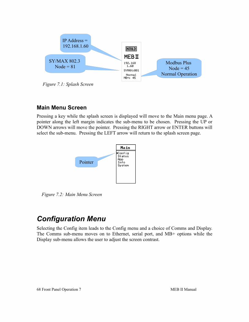
Splash Screen
The main page shows the IP Address of the MEBII and the MB+ node number and status, and SY/MAX 8023 drop number (if enabled).
Error conditions may be displayed on the splash screen as they occur. Indications for duplicate IP Address, duplicate SY/MAX 802.3 node, or the various Modbus Plus status descriptions are shown. Certain errors will flash the backlight until a key is pressed to draw attention to the MEBII.
MEB II Manual 7 Front Panel Operation 67
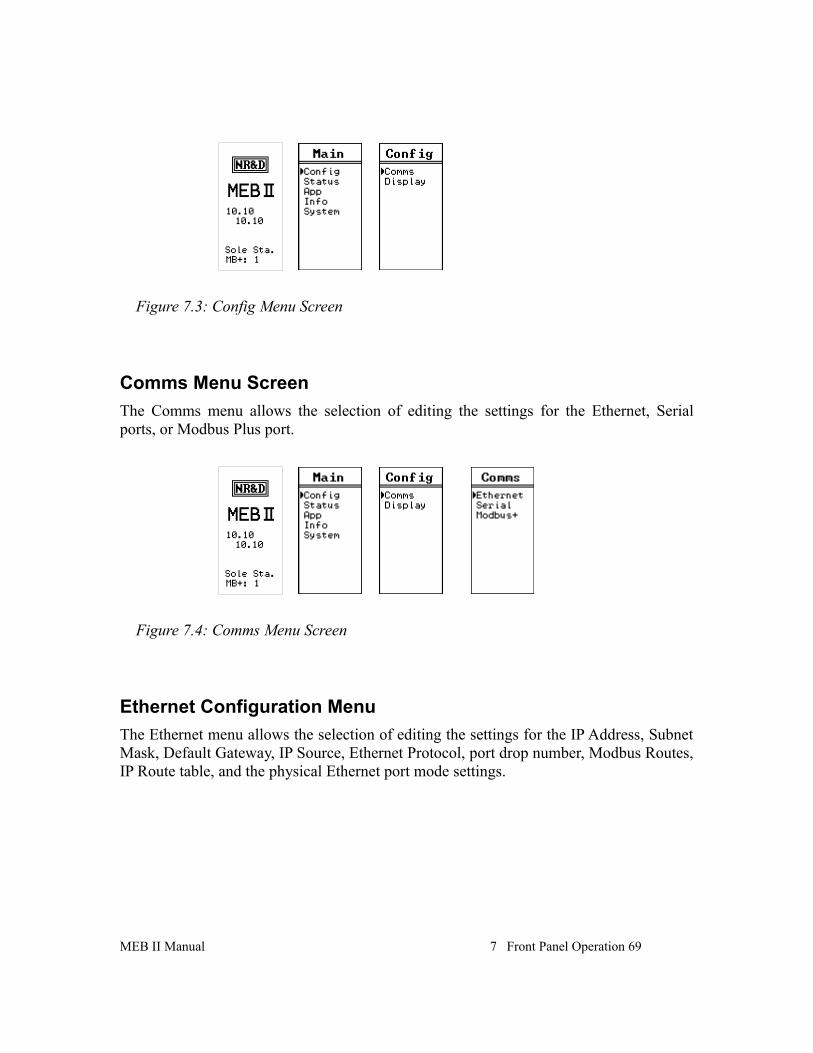
Main Menu Screen
Pressing a key while the splash screen is displayed will move to the Main menu page. A pointer along the left margin indicates the sub-menu to be chosen. Pressing the UP or DOWN arrows will move the pointer. Pressing the RIGHT arrow or ENTER buttons will select the sub-menu. Pressing the LEFT arrow will return to the splash screen page.
Configuration MenuSelecting the Config item leads to the Config menu and a choice of Comms and Display. The Comms sub-menu moves on to Ethernet, serial port, and MB+ options while the Display sub-menu allows the user to adjust the screen contrast.
68 Front Panel Operation 7 MEB II Manual
Figure 7.2: Main Menu Screen
Pointer
Figure 7.1: Splash Screen
Modbus Plus Node = 45
Normal Operation
SY/MAX 802.3 Node = 81
IP Address = 192.168.1.60
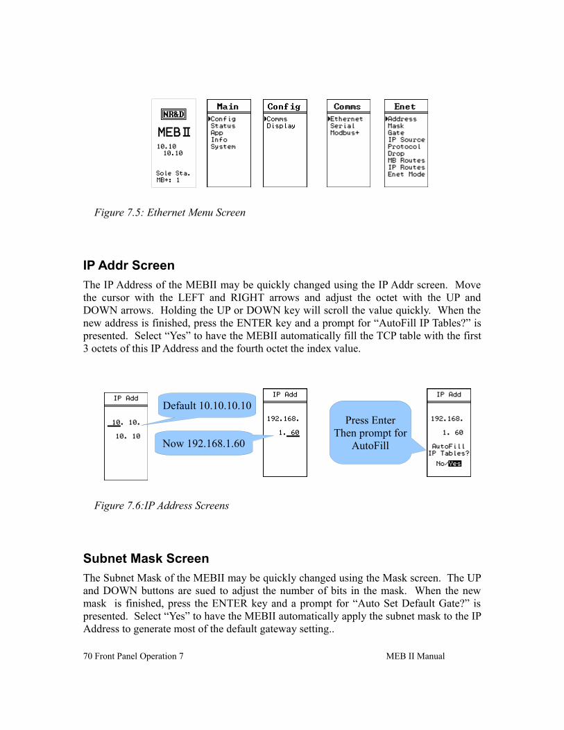
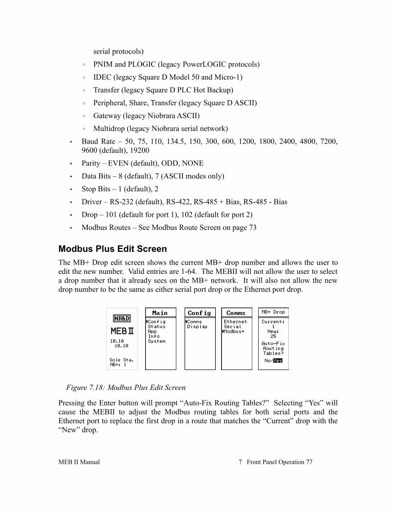
Comms Menu Screen
The Comms menu allows the selection of editing the settings for the Ethernet, Serial ports, or Modbus Plus port.
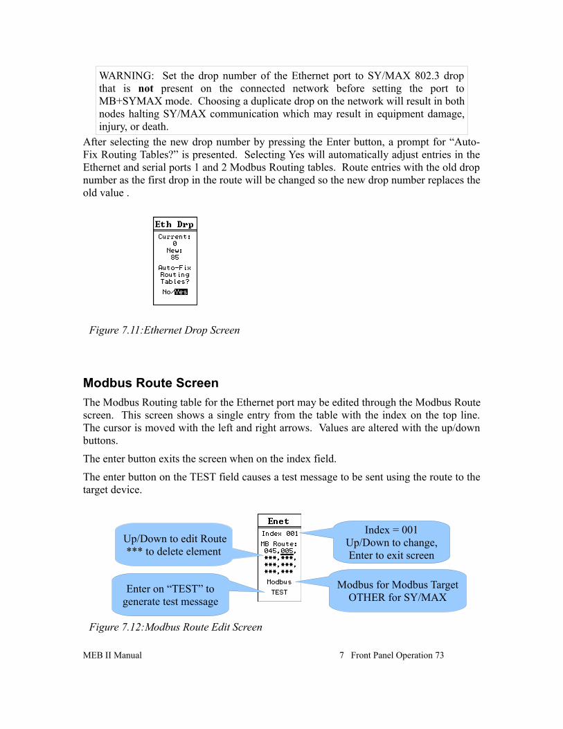
Ethernet Configuration Menu
The Ethernet menu allows the selection of editing the settings for the IP Address, Subnet Mask, Default Gateway, IP Source, Ethernet Protocol, port drop number, Modbus Routes, IP Route table, and the physical Ethernet port mode settings.
MEB II Manual 7 Front Panel Operation 69
Figure 7.3: Config Menu Screen
Figure 7.4: Comms Menu Screen
IP Addr Screen
The IP Address of the MEBII may be quickly changed using the IP Addr screen. Move the cursor with the LEFT and RIGHT arrows and adjust the octet with the UP and DOWN arrows. Holding the UP or DOWN key will scroll the value quickly. When the new address is finished, press the ENTER key and a prompt for “AutoFill IP Tables?” is presented. Select “Yes” to have the MEBII automatically fill the TCP table with the first 3 octets of this IP Address and the fourth octet the index value.
Subnet Mask Screen
The Subnet Mask of the MEBII may be quickly changed using the Mask screen. The UP and DOWN buttons are sued to adjust the number of bits in the mask. When the new mask is finished, press the ENTER key and a prompt for “Auto Set Default Gate?” is presented. Select “Yes” to have the MEBII automatically apply the subnet mask to the IP Address to generate most of the default gateway setting..
70 Front Panel Operation 7 MEB II Manual
Figure 7.5: Ethernet Menu Screen
Figure 7.6:IP Address Screens
Default 10.10.10.10
Now 192.168.1.60
Press EnterThen prompt for
AutoFill
Default Gate Screen
The Default Gateway of the MEBII is edited just like the IP Address. The LEFT and RIGHT buttons move the cursor while the UP and DOWN buttons are sued to adjust the value. Press ENTER to accept the new value.
Set the Default Get to 0.0.0.0 to disable routing operation outside the local subnet.
IP Source Screen
The MEBII may have a fixed IP Address or use BOOTP or DHCP to have its IP settings configured. The IP Source screen allows the user to configure the appropriate setting. Use the UP and DOWN buttons to select the setting. DHCP and BOOTP typically require the server to be configured for the MAC address of the MEBII's Ethernet port.
MEB II Manual 7 Front Panel Operation 71
Figure 7.7:Subnet Mask Screens
Default 255.0.0.0
Now 255.255.255.0
Press EnterThen prompt for
Auto Set DefaultGate
Figure 7.8:Default Gate Screen
After Auto Set
Now 192.168.1.1
This MACC address is shown on the screen in hexadecimal (00:20:BD:0C:35:04).
Ethernet Protocol Screen
The Ethernet port may be configured for only Modbus/TCP or a combination of Modbus/TCP plus SY/MAX 802.3 for support of legacy SY/MAX Ethernet devices. The Protocol screen allows the setting of the mode.
WARNING: Set the drop number of the Ethernet port to SY/MAX 802.3 drop that is not present on the connected network before setting the port to MB+SYMAX mode. Choosing a duplicate drop on the network will result in both nodes halting SY/MAX communication which may result in equipment damage, injury, or death.
Ethernet Drop Screen
The drop number of the Ethernet port defaults to 0 and rarely needs to be changed. This drop number is used to set the SY/MAX 802.3 Ethernet node number when the Ethernet port is set to MB+SYMAX protocol mode.
72 Front Panel Operation 7 MEB II Manual
Figure 7.9:IP Source Screen
Figure 7.10:Ethernet Protocol Screens
WARNING: Set the drop number of the Ethernet port to SY/MAX 802.3 drop that is not present on the connected network before setting the port to MB+SYMAX mode. Choosing a duplicate drop on the network will result in both nodes halting SY/MAX communication which may result in equipment damage, injury, or death.
After selecting the new drop number by pressing the Enter button, a prompt for “Auto-Fix Routing Tables?” is presented. Selecting Yes will automatically adjust entries in the Ethernet and serial ports 1 and 2 Modbus Routing tables. Route entries with the old drop number as the first drop in the route will be changed so the new drop number replaces the old value .
Modbus Route Screen
The Modbus Routing table for the Ethernet port may be edited through the Modbus Route screen. This screen shows a single entry from the table with the index on the top line. The cursor is moved with the left and right arrows. Values are altered with the up/down buttons.
The enter button exits the screen when on the index field.
The enter button on the TEST field causes a test message to be sent using the route to the target device.
MEB II Manual 7 Front Panel Operation 73
Figure 7.11:Ethernet Drop Screen
Figure 7.12:Modbus Route Edit Screen
Index = 001Up/Down to change,Enter to exit screen
Up/Down to edit Route*** to delete element
Enter on “TEST” to generate test message
Modbus for Modbus TargetOTHER for SY/MAX
The TEST message is an opcode 03 Modbus Holdign Register read of remote regsiters 8188. Possible results from this read are:
• A valid reply is received from the target slave. The screen will show PASS along with the decimal value of the remote register 4x8188. On older SY/MAX PLCs, this value is the PLC model number.
• A valid error reply is received from the target slave. The screen will show PASS along with the returned error code. Possible errors are:
◦ Error 01 = Illegal Opcode. This means that the slave does not support Modbus opcode 03 (Holding Register read). The slave is replying to the test message, it just does not support the test message.
◦ Error 02 = Illegal register. This means that the slave does not have Holding Register 4x8182. This is also a PASS condition, it just means that the test message asked for a register that does not exist in the slave.
• The network was unable to receive a reply from the slave. This is a FAIL condition with the error message Downstream Timeout.
• The MEBII was unable to generate the query because the first drop in the route was not a valid drop number of another port in the MEBII. The FAIL message will show
IP Route Screen
The IP Routing table for the Ethernet port may be edited through the IP Route screen. This screen shows a single entry from the table with the index on the top line. The cursor is moved with the left and right arrows. Values are altered with the up/down buttons.
The enter button exits the screen when on the index field.
The enter button on the ZERO field causes the IP Address to be set to 0.0.0.0. This is handy for zeroing an entry for SY/MAX 802.3 Ethernet entries.
74 Front Panel Operation 7 MEB II Manual
Figure 7.13:Modbus Route Test Results Screens
Pass Fail
The AUTO field sets the entry to the MEB's IP Address with the last octet set to match the index.
Ethernet Mode Screen
The Ethernet Mode screen allows the physical configuration of the Ethernet port. The port defaults to “AUTO” mode which automatically sets itself to match the attached device. The possible settings are:
• AUTO
• 10BaseT – Full Duplex
• 10BaseT – Half Duplex
• 100BaseT – Full Duplex
• 100BaseT – Half Duplex
MEB II Manual 7 Front Panel Operation 75
Figure 7.14:IP Route Screen
Index = 002Up/Down to change,Enter to exit screen
Up/Down to edit AddressLeft/Right to change field
Enter on “AUTO” to Auto-fill the entry
ZERO – press Enter to zero the entire entry
Figure 7.15:Ethernet Port Mode Screens
Serial Port Menu
The Serial menu allows the selection a particular serial port to edit. Choices are Port 1 and Port 2.
Port 1 Menu
Both serial port share the same menu list.
Settings available fro the two serial ports are:
• Protocol
◦ Modbus RTU (default)
◦ Modbus ASCII
◦ Modbus Host (RTU with special translations)
◦ Chevron (combination Modbus RTU master with RNIM master)
◦ Dual Slave (combination Modbus RTU slave and SY/MAX slave)
• Drop – 101 (default for port 1), 102 (default for port 2)
• Modbus Routes – See Modbus Route Screen on page 73
Modbus Plus Edit Screen
The MB+ Drop edit screen shows the current MB+ drop number and allows the user to edit the new number. Valid entries are 1-64. The MEBII will not allow the user to select a drop number that it already sees on the MB+ network. It will also not allow the new drop number to be the same as either serial port drop or the Ethernet port drop.
Pressing the Enter button will prompt “Auto-Fix Routing Tables?” Selecting “Yes” will cause the MEBII to adjust the Modbus routing tables for both serial ports and the Ethernet port to replace the first drop in a route that matches the “Current” drop with the “New” drop.
MEB II Manual 7 Front Panel Operation 77
Figure 7.18: Modbus Plus Edit Screen
Display Edit Screen
The Display screen allows the user to adjust the contrast value for the display. The UP and DOWN arrows allow the changing of the setting. The ENTER or LEFT arrows accept the new value.
Status Menu Screens
The Status menu item gives access to physical status and communication statistics for all ports.
Stats Screen
Each port has multiple screens to give statistical counters about communication through the port. LEFT and RIGHT arrows change between ports. UP and DOWN move between pages for a given port. ENTER returns to the previous menu.
78 Front Panel Operation 7 MEB II Manual
Figure 7.19: Display Contrast Edit Screen
Figure 7.20: Status Menu Screen
Enet Status Screen
The Enet status screen shows the current physical connection status of the Ethernet port.
MB+ Status Screen
The MB+ status screen shows information about the state of the MB+ port.
MEB II Manual 7 Front Panel Operation 79
Figure 7.21: Stats Screens
Figure 7.22: Status Menu Screen
Figure 7.23: Status Menu Screen
App MenuThe APP menu allows the user to halt the MEBII application. This feature should only be used when directed by Niobrara Technical Support.
Switch Screen
The Switch screen allows the user to HALT or RUN the MEBII application. The MEM PROT setting is ignored at this time and is the same as RUN.
80 Front Panel Operation 7 MEB II Manual
Figure 7.24: App Menu Screen
Figure 7.25: Switch Screen
Info MenuThe Info Menu provides access to various information about the MEBII firmware and network connections.
MAC Address Screen
The MAC address screen shows the hardware address of the Ethernet port in hexadecimal. This information is useful when the IP Address is set by BOOTP or DHCP.
MEB II Manual 7 Front Panel Operation 81
Figure 7.26: Info Menu Screen
Figure 7.27: MAC Address Screen
Serial Number Screen
This screen shows the serial number of the MEBII.
Versions Screen
The Versions menu gives access to the MEBII firmware, DUCM firmware, and boot version.
MB+ Drops Screen
The MB+ drops screen shows the addresses of local MB+ nodes that are recognized by the MEBII. This page is dynamically updated and may stretch to show more than one screen. The UP and DOWN keys may be used to move between screens if needed.
The MB+ node of the MEBII is highlighted.
82 Front Panel Operation 7 MEB II Manual
Figure 7.28: Serial Number Screen
Figure 7.29: Versions Screen
Enet Drops Screen
The Enet drops screen will show the SY/MAX 802.3 drops accessible to the MEBII. This page may extend beyond a single screen and the UP and DOWN buttons are used to move between screens.
Any drop numbers local the MEBII are highlighted. This includes the Ethernet port and any other port with “ON ETHERNET” set to YES.
MEB II Manual 7 Front Panel Operation 83
Figure 7.30: MB+ Drops Screen
Figure 7.31: SY/MAX Ethernet Drops Screen
System MenuThe System menu provides access to the front panel password, reboot, and reset to factory defaults.
Reboot Screen
This screen allows the user to force a hardware reboot of the MEBII without physically removing the power.
Factory Defaults Screen
The Factory screen allows the user to quickly reset the MEBII to factory defaults. The reset process also includes a reboot. Selecting “NO” will return to the previous menu without altering the current setup.
84 Front Panel Operation 7 MEB II Manual
Figure 7.32: Reboot Screen
Figure 7.33: Factory Defaults Screen
Password Screen
The MEBII may have a password enabled to limit front panel operation. The password is a four digit number (0000-9999) that must be entered before settings are altered. Once the password is entered, it settings may be altered until a reboot or the backlight timeout occurs.
Setting the password to 0000 disables the feature.
MEB II Manual 7 Front Panel Operation 85
Figure 7.34: Password Screen
8 Recommended Cables
RS-232 Cables
MM1 (PC to MEBII)
The Niobrara MM1 cable may be used to connect the MEBII RS-232 port to a standard PC 9-pin male port. The pinout is shown in Figure 8.1.: MM1 Serial Cable.
Figure 8.1.: MM1 Serial Cable
RJ-45 Connection PC Serial Port Pin
1 1
2 2
3 3
4 4
5 5
6 6
7 7
8 8
9
MM2 (Modicon PLC to MEBII)
The Niobrara MM2 cable may be used to connect the MEBII RS-232 port to a standard Modicon 9-pin female PLC programming port. These ports are common on the Quantum PLC, Compact 984, 984, BM85 Bridge Mux, and other older Modicon products. This is the same cable as the MM1 with a male 9-pin connector. The pinout is shown in Figure8.2.: MM2 Serial Cable.
MEB II Manual 87
Figure 8.2.: MM2 Serial Cable
RJ-45 Connection Modicon PLC Serial Port Pin
1 1
2 2
3 3
4 4
5 5
6 6
7 7
8 8
9
MM3 (MEBII to emulate a 9-pin PC port)
The Niobrara MM3 cable may be used to make the MEBII RS-232 port appear as a standard PC 9-pin male port. This cable is often used along with an MM1 cable to connect two RJ-485 RS-232 ports together such as an MEBII to a newer Compact 984 PLC. The pinout is shown in Figure 8.3.: MM3 Serial Cable.
Figure 8.3.: MM3 Serial Cable
RJ-45 Connection PC Serial Port Pin
1 1
2 2
3 3
4 4
5 5
6 6
7 7
8 8
9
88 Recommended Cables 8 MEB II Manual
RS-485 Cables
MU7 (MEBII to SY/MAX)
The Niobrara MU7 cable is used to connect the RS-485 port of the MEBII to a standard SY/MAX DB9 female port. This cable is normally used to connect the MEBI directly to a SY/MAX PLC or NIM module.
NOTE: The MEBII port driver mode is normally set to RS422 when connected to a SY/MAX serial port.
Figure 8.4.: MU7 Serial Cable
Phoenix 5-pin Connection SY/MAX Port
TX(+) 1 TX-
TX(-) 2 TX+
RX(+) 3 RX-
RX(-) 4 RX+
Shield 5
6
7
8
9
Driver Mode: RS-422
MEBII Master to 4-wire RS-485 Slaves
The MEBII may be used to be a master on a 4-wire RS-485 network. An example of this network is a string of PowerLogic meters attached to the MEBII.
An external terminator should be used at the last slave across its RX pair. Normally, this is a 120 ohm resistor or the PowerLogic MCT-485.
The Driver Mode for the MEBII port should be set to RS-422. This mode enables the transmitter of the port at all times to bias the receivers of all of the slaves. This mode also enables the internal termination and bias of the MEBII's receiver.
Belden 8723 or equivalent is recommended for this type of network.
The shield wire should only be grounded at one location - usually at the master. A simple
MEB II Manual 8 Recommended Cables 89
method of grounding the shield is to connect the Shield terminal of the MEB's RS-485 connector to the Earth Ground terminal of the MEBII's power supply connector.
Figure 8.5.: 4-wire RS-485 Master
Phoenix 5-pin Connection
Slave A Slave B Slave C
TX(+) RX(+) RX(+) RX(+)
TX(-) RX(-) RX(-) RX(-)
RX(+) TX(+) TX(+) TX(+)
RX(-) TX(-) TX(-) TX(-)
Shield Shield Shield Shield
Driver Mode: RS-422 (term and bias enabled)
Terminator only on last slave
MEBII to 2-wire RS-485
The MEBII may be used as a master or slave on a 2-wire RS-485 network. An example of this network is a string of 2-wire RS-485 PowerLogic meters attached to the MEBII.
The MEBII must have the TX(+) and RX(+) lines jumpered together to make the (+) connection on a 2-wire network. The TX(-) and RX(-) lines must also be jumpered together to connect to the (-) line.
Terminator should be used at the last slave on each end of the daisy-chain. Normally, this is a 120 ohm resistor.
Bias should only be enabled on one device of the 2-wire network. Typically, the bias is enabled at the Master device since it is required to be active on the network.
If the MEBII is the Master of the network, then it should be located at one end of the daisy-chain and the Driver Mode should be set to RS485+Bias. The RS845+Bias mode enables the internal bias and termination resistors.
NOTE: RS485+Bias mode always enables both the internal termination and bias resistors. If another device on the 2-wire network is providing the bias then the MEBII port must be set for RS485-Bias and an external termination resistor must be used.
Belden 9841 or equivalent is recommended for this type of network.
The shield wire should only be grounded at one location - usually at the master. A simple method of grounding the shield is to connect the Shield terminal of the MEB's RS-485 connector to the Earth Ground terminal of the MEBII's power supply connector.
90 Recommended Cables 8 MEB II Manual
Figure 8.6.: 2-wire RS-485 Network with internal Bias
Phoenix 5-pin Connection
Node A Node B Node C
TX(+) (+) RX(+) RX(+)
TX(-) (-) RX(-) RX(-)
RX(+)
RX(-)
Shield Shield Shield Shield
Driver Mode: RS485+Bias
Terminator on last slave
Figure 8.7.: 2-wire RS-485 Network without internal Bias
Node A Phoenix 5-pin Connection
Node B Node C
RX(+) TX(+) RX(+) RX(+)
RX(-) TX(-) RX(-) RX(-)
RX(+)
RX(-)
Shield Shield Shield Shield
Terminator on last slave
Driver Mode: RS485-Bias
Bias on some slave, could be same as
terminator
Terminator on last slave
MEB II Manual 8 Recommended Cables 91
9 Web Server
The MEBII uses a built-in Web server for remote configuration over the Ethernet network. This Web server requires the use of Javascript.
LoginThe MEBII Web server supports two user access levels: “User” and “Admin”. These usernames are not changeable and are not case sensitive. “User” provides read-only access to view the configuration of the MEBII. “Admin” provides full configuration edit capabilities as well as backup/restore and firmware upgrade.
The Default Password for each user is shown below and are not case sensitive:
Username: user
Password: user
Username: admin
Password: master
Figure 9.1 shows the Login page. Enter the appropriate username and password to gain access to the MEBII.
If the “User” account is used and the operator attempts to modify a setting in the MEBII, a pop-up notification will appear to announce that modifications are not allowed for this user level. (See Figure 9.2)
MEB II Manual 93
94 Web Server 9 MEB II Manual
Figure 9.2 “User” attempting to modify settings
Figure 9.1: Login Screen
Home
The typical web page includes an AJAX status box showing the state of the Javascript communication between the browser and the MEBII. The background of this box turns red when comm errors are occurring.
The menu tree may has the following branches: Home, Configuration, Tools, and Admin.
NOTE: Admin is not present when logged in as “user”.
ConfigurationThe Configuration menu provides access to the settings for Ethernet, Port 1, Port 2, and Modbus Plus.
Ethernet
There are pages for setting the IP Address, Ethernet Protocol, Modbus Routing, TCP Client Routing, and I/O Scanner.
MEB II Manual 9 Web Server 95
Figure 9.3: Home
AJAXComms Status
Menu Tree
Login User ID
IP Settings
The IP Settings page allows the Admin to select the IP Parameters for the module.
96 Web Server 9 MEB II Manual
Ethernet Port Parameters
This page allows the Admin to configure the MEBII to operate in Modbus/TCP or SY/AMX+Modbus/TCP mode and set the SY/MAX 802.3 drop number.
MEB II Manual 9 Web Server 97
Modbus Routing for Ethernet Port
The Ethernet port has 254 entires in its Modbus Routing table. The Route typically consists of the drop number of the outbound MEBII port followed by any additional drops needed to reach the target.
NOTE: Entries with no route will allow that index to access the MEBII's internal registters.
NOTE: Entries with the first drop in the route that does not match a drop number of any port on the MEBII will access the MEBII's internal registers.
NOTE: Using the Ethernet port's drop number as the first drop in the route will cause the message to be routed back out the Ethernet port. This feature allows the MEBII to translate between Modbus/TCP and SY/MAX 802.3 Ethernet.
98 Web Server 9 MEB II Manual
TCP Routing Table
The TCP Routing table is used for Modbus/TCP Client operation.
NOTE: SY/MAX 802.3 Ethernet client operation is selected by setting the drop number IP Address to 0.0.0.0.
MEB II Manual 9 Web Server 99
I/O Scanner
The MEBII includes a Modbus/TCP I/O Scanner. This scanner allows automatic Read, Write, and Read+Write time based messages to be generated between the MEBII and up to 128 Modbus TCP servers. The I/O Scanner operates on the Mailbox registers (1-2048) in the MEBII's internal registers.
100 Web Server 9 MEB II Manual
Serial Ports
Port Parameters
The Port Parameters page will show the settings for a given serial port. Various protocol modes have different settings that may be displayed. Changing the protocol mode will prompt the “Admin” to “Apply typical settings” for the new mode. Selecting “OK” will change many of the settings to match the normal usage of the new mode.
MEB II Manual 9 Web Server 101
Serial Port Modbus Routing Table
Each serial port includes its own 254 entry look-up table for Modbus Slave operation. The first drop in the Route field is the drop number of the outbound MEBII port.
102 Web Server 9 MEB II Manual
Serial Port Auto Scan
Each serial port may be configured to automatically poll attached slave(s) on a timed interval. This table provides the configuration for each of the 48 possible entries.
NOTE: The Auto Scan Table for port 2 is disable when the MEBII is in Hot Modbus Plus operation.
NOTE: Port 2 Auto Scan may be used to generate read/write messages onto MB+ by entering the MB+ port drop number as the first entry in the Route field.
MEB II Manual 9 Web Server 103
Modbus Plus Port Parameters
The MB+ port settings may be altered on this page.
104 Web Server 9 MEB II Manual
Modbus Plus Global Data
The MEBII may be configured to publish up to 32 words of data from its mailbox registers (Holding Registers 1-2048) as port of MB+ Global Data. It may also be configured to subscribe to the Global Data outputs of each of the other 63 nodes on the MB+ network. The subscription data will be placed in the mailbox registers of the MEBII.
NOTE: Hot Modbus Plus operation uses the Global Data output and is thus not available for customer use.
MEB II Manual 9 Web Server 105
106 Web Server 9 MEB II Manual
StatisticsPages are provided for statistical counter pages for each port.
Many of these pages have “Reset Counter” buttons that allow either the “User” or “Admin” to zero the counters.
NOTE: These counters are typically unsigned words and will roll over from 65535 to 0 with no indication that a rollover has occurred.
NOTE: These counters do not survive a power cycle/reboot.
Ethernet Router Stats
The Ethernet Router page shows counters for the SY/MAX / Modbus router for this port.
MEB II Manual 9 Web Server 107
SY/MAX 802.3 Ethernet Nodes
This table shows all of the visible SY/MAX Ethernet devices on the MEBII's local Ethernet network.
NOTE: The MEBII Ethernet port must be set for SY/MAX+Modbus mode for this table to be accurate.
Any SY/MAX Ethernet drop number occupied by this MEBII is highlighted in green. This includes any serial port or the MB+ port that is set for “ON Ethernet YES”. Serial ports that have a drop number greater than 100 and configured for “ON Ethernet YES” will also consume the SY/MAX drop number minus 100.
Drop Number of peer devices are highlighted in blue.
108 Web Server 9 MEB II Manual
Serial Port
Serial ports 1 and 2 have counter pages to show the SY/MAX / Modbus router information associated with that port.
MEB II Manual 9 Web Server 109
Port 2 Hot Modbus Statistics
The statistics page for Port 2 is different when the MEBII is configured for Hot Modbus Plus operation.
110 Web Server 9 MEB II Manual
Modbus Plus Router
The Router statistics page shows the normal SY/MAX / Modbus router counters for the MB+ port.
MEB II Manual 9 Web Server 111
MB+ Chipset
The MB+ Chipset page shows information provided by the MB+ chipset. These counters are not resettable.
112 Web Server 9 MEB II Manual
Modbus Plus Nodes
This table shows all possible 64 MB+ stations on the MEBII's local MB+ network. The MEBII's drop number is highlighted in green. All other visible nodes are highlighted in blue.
MEB II Manual 9 Web Server 113
114 Web Server 9 MEB II Manual
MEB II Manual 9 Web Server 115
Module Info
The Module Info page shows the MEBII's serial number and various firmware versions.
116 Web Server 9 MEB II Manual
Config Overview
The Config Overview page provides a complete listing of all of the configuration of the MEBII. This page may be printed to provide a hard copy of the module's setup.
Note: This page takes several seconds to populate. At the end of the configuration is a text line “This is the end of the Configuration Listing.”
MEB II Manual 9 Web Server 117
Register Viewer
The Register Viewer allows the User or Admin to view/modify register data in a target. The Target is determined using the Modbus Routing Table Index for the Ethernet Port.
NOTE: The present fimware only allows access to Modbus Index 255 (the MEBII itself).
Access to 4x (Holding Registers) or 6x (Files) are supported.
Multiple viewing windows may be opened. Windows may be closed by clicking the “X” in the upper left corner of the window. The polling rate of each viewing window is adjustable with the pull-down in the upper corner of each window.
118 Web Server 9 MEB II Manual
Admin MenuThe Admin menu heading is only shown when the “Admin” account is used for the web login.
Change Passwords
The Change Password page allows the Administrator to modify the “Admin” and/or “User” passwords.
MEB II Manual 9 Web Server 119
Configuration Backup
The configuration of the MEBII may be pulled from the MEBII and saved as an XML file on the PC. The common method is to right click the “here” link and choose “Save Link As...” or “Save Target As...” and then save the file.
The default filename is of the form: config_192_168_1_14.mebii where 192.168.1.14 is the IP Address of the MEB in question.
120 Web Server 9 MEB II Manual
Configuration Restore
The Restore link will allow the Admin to restore a previously saved backup file to the MEBII.
MEB II Manual 9 Web Server 121
Hot Modbus Plus
The Hot Modbus Plus page may be used to initialize the MEBII as the first Primary or Secondary unit.
122 Web Server 9 MEB II Manual
Firmware Update
The Firmware Update page allows the Admin to install a new version of the MEBII.qrc file.
NOTE: It is always recommended that a new backup of the MEBII configuration be done before updating the firmware.
The new firmware is usually installed in the c:\Niobrara\Firmware\ folder.
MEB II Manual 9 Web Server 123
Reset to Factory Defaults
The MEBII may be reset to Factory Defaults by typing “YES” into the text field. Resetting to Factory using this web page will keep the current Ethernet settings (IP Address, Subnet Mask, and Default Gateway) but will revert all other settings to factory default.
NOTE: Resetting the MEBII to Factory Default using the front panel LCD will also revert the IP settings to 10.10.10.10.
124 Web Server 9 MEB II Manual
10 MEBSW32
NOTE: MEBSW32 does not offer full support of the features in the MEBII-X (webserver) versions. The MEBII-X features full 254 entry Modbus routing tables for Ethernet and both serial ports, as well as the I/O Scanner configuration.Do not rely on the MEBSW32 offline configuration for backup. Use the backup/restore feature of the web server.
MEBSW32 is a MS Windows32 console application to allow online/offline configuration of the MEBII and older MEB hardware.
Startup Screen
The fist time that MEBSW32 is started, it will show a screen like Figure 10.1. The date in the upper right corner (06Aug2010) is the revision of MEBSW32. The Error
MEB II Manual 125
Figure 10.1: Startup Screen
notification in the lower right corner indicates that the program is unable to locate the setup file.
Note: Press the F10 key or the Escape (ESC) to move past an error notification.
This particular error will not be displayed if the setup file is saved. Clearing this error will immediately drop into the “Setup, Serial communication” screen.
This screen is used to configure the connection between the PC and the target MEBII. In this case, the connection is Modbus/TCP Ethernet to the target 10.10.10.10 using index 255. See section Serial communication on page 142 for more information.
Pressing “Enter” after selecting the Index field will pop up the “Write setup to startup file?” window. Pressing “Enter” or “y” will save the file and avoid the error on the next startup.
126 MEBSW32 10 MEB II Manual
Figure 10.2: Setup Serial Screen
Main MenuThe Main Menu is shown in Figure . All menu items may be selected by using the arrow keys to move around or by using the yellow shortcut letter.
• “N” for oNline – Edit the configuration directly in the MEBII in real time.
• “F” for oFfline – Edit, Save, Print offline copies of the MEBII's configuration.
• “U” for Utility – View registers, statistics, MB+ station lists.
• “S” for Setup – Configure the PC connection.
• “Q” for Quit – Exit the MEBSW32 program.
MEB II Manual 10 MEBSW32 127
Figure 10.3: Setup Serial Screen
oNline MenuThe oNline menu is used to directly edit parameters in the MEBII.
• Edit port parameters – Adjust settings for the Ethernet, Serial, and MB+ ports.
• edit Modbus routing – Configure routing tables for the Ethernet and serial ports.
• edit Auto scan table – Configure the automatic polling tables for the serial and MB+ ports.
• edit Global data table – Modify the MB+ Global Data Table.
• edit TCP routing – Modify the Modbus/TCP client IP Address table.
128 MEBSW32 10 MEB II Manual
Figure 10.4: Setup Serial Screen
Edit port parameters
The oNline edit port parameters screen has a column for the Ethernet port, each serial port, and the MB+ port. The arrow keys are used to move the highlighted cell around. The space bar and + and – keys are used to modify the values.
MEB II Manual 10 MEBSW32 129
Figure 10.5: oNline Menu
Figure 10.6: oNline edit port parameters Screen
NOTE: Care must be exercised while editing online parameters. Changing settings on the port the computer is using will result in a loos of communication.
Edit Modbus routing
The Modbus Routing screen is used to set the lookup tables for Ethernet clients and serial Modbus master.
The left column is the Modbus slave or Modbus/TCP Index. The Ethernet port has 255 possible entries. Each serial port supports 128 entries. The F4 key is used to alter the starting slave address for the serial port tables. The F4 key also allows the selection of “Micrologic Support”.. Micrologic support is a special feature that takes the route for each of the first 50 drop numbers in the table and automatically support the same route for 50+x, 100+x, and 150+x drops.
The center column is either “MODBUS” or “OTHER”. MODBUS is used when the target device is a Modbus slave. OTHER is used when the target slave is SY/MAX or some other device that is not Modbus.
The ROUTE field is used to define the path to the target. The first drop in the route should be the drop number of the MEBII port heading towards the target slave. The example above shows routes of 1,x where 1 is the drop number of the MB+ port and x is the MB|drop number of the target PLC.
Auto Scan Edit
The Auto Scan feature allows a serial port to automatically generate up to 48 sequential messages on a fixed time interval. The messages may be either a read or a write. Each
130 MEBSW32 10 MEB II Manual
Figure 10.7: Modbus Routing Screen
message includes the starting local mailbox register, the starting remote register, the count, the direction (READ or WRITE), and the route.
F4 edits the Status bit map registers. These registers provide 48 bits to indicate the success or failure of the scan.
F8 auto increments the next entry.
Global Data
The MEBII MB+ port may participate in Global Data. This feature allows each node on the MB+ network to publish up to 32 words that are visible by all other nodes on each token pass. The published mailbox data is set in the OUTPUT field in the lower right corner.
The REG field is the MEBII's mailbox register and must be within the range of 1-2048.
The COUNT field is set to 0 to disable the subscription and has a maximum value of 32.
MEB II Manual 10 MEBSW32 131
Figure 10.8: Auto Scan Screen
TCP Routing
The TCP Routing screen gives access to the 200 entries the table. This table is used to associate the drop number in the route following the Ethernet port drop number to an IP Address. The Downstream Route feature may be used to add the Modbus/TCP Destination Index in the rare situation where all 5 MB+ drops in the route are already used by the time the message reaches the TCP table.
The Auto-Fill feature of the IP table on the MEBII's front panel will automatically place the first three octets of the new IP Address in each of the 200 entires of this table. The fourth octet will simply be the index value for the entry.
132 MEBSW32 10 MEB II Manual
Figure 10.9: Global Data Screen
offline MenuThe oFfline menu allows MEBII configuration without a physical connection to the hardware.
MEB II Manual 10 MEBSW32 133
Figure 10.10: TCP Routing Screen
Figure 10.11: TCP Routing Screen
Read from disk to memory
The oFline, Read from disk to memory menu item allow the MEBSW32 program to read a previously saved configuration file from the computer's hard disk into the offline memory. This file may then be viewed, modified, printed, saved, or sen to an MEBII. The filename must be a maximum of 8 characters and is chosen from files with the extension .MEB.
The arrow keys may be used to move around the list of stored files or the filename may besimply typed into the File to read: box. Moving the cursor around to an item encased by [] will choose that drive letter or folder name.
Write from memory to disk
The oFfline, Write from memory to disk is used to save the current offline memory to a file on the PC. The navigation and file name operation is the same as the “Read from disk to memory”.
Edit configuration in memory
The oFfline, Edit configuration in memory screen works just like the oNline Edit port parameters version on page 129.
134 MEBSW32 10 MEB II Manual
Figure 10.12: Read File from Disk Screen
edit Modbus Routing
The oFfline, edit Modbus routing screen works just like the oNline Edit Modbus routing on page 130.
edit Global data table
The oFfline, edit Global data table screen works just like the oNline,Global Data on page 131
edit TCP routing table
The oFfline, edit TCP routing table screen works just like the oNline, TCP Routing on page 132
Send memory to module
The oFfline, Send memory to module screen sends all of the oFfline data to the MEBII.
NOTICE: This action will overwrite all data in the MEBII and may potentially cause the PC to loose communication with the MEBII.
Note: The data sent to the MEBII will not be saved in the module until Utility, Write setup to EEPROM is completed.
Fetch memory from module
This menu item copies all of the configuration from the MEBII to the oFfline section of MEBSW32.
Print configuration in memory
A hard copy of the oFfline configuration may be created using the Print configuration in memory. Choose LPT1: to print directly to port LPT1. A text file name may also be entered to print directly to a file.
Delete configuration file
This screen is used to remove a .MEB file from the computer. Select the file and pres enter to delete the file from the computer.
Copy offline to module flash
This menu item is to supported by the MEBII. It is only used with the older SY/MAX versions of the MEB.
MEB II Manual 10 MEBSW32 135
Quit offline functions
This menu item returns to the main menu. Pressing the ESC key performs the same task.
Utility MenuThe Utility menu offers several handy features to troubleshoot a system.
View registers
The View registers screen gives a Modbus register viewer/modifier screen that may access Holding (4x) or Analog Input (3x) registers in the target device. Use the Serialcommunication and Register viewer pages to choose the target device and viewable register type and range.
The register data is shown in Hex, unsigned, signed, and binary form. Use the arrow, page up and down, and home keys to move the cursor around. Use the number keys to modify the register's content. Pressing Enter will send the new data to the target.
NOTE: Writing data to a target device may cause unexpected behavior, equipment damage, personal injury or death.
136 MEBSW32 10 MEB II Manual
Figure 10.13: Utility Menu Screen
Jump to a particular register location by typing in a new number while the cursor is in the far left column.
view module Revision
The view module Revision screen will show the MEBII's current firmware revision.
MEB II Manual 10 MEBSW32 137
Figure 10.14: Utility Menu Screen
Figure 10.15: Utility View Module Revision Screen
view Statistics
The MEBII contains many pages of statistical information about the operation of its various ports. There are pages for the Ethernet port, both serial ports, and the MB+ port. Most port pages include multiple screens accessed with the Page Up and Page Down buttons. Pressing the + and – or “space bar” buttons will move between port pages. Use the “z” or “0” key s to zero the counters for a given port.
138 MEBSW32 10 MEB II Manual
Figure 10.16: Ethernet Statistics Screen
Figure 10.17: MB+ Statistics Screen
Terminal emulator
MEBSW32 includes a simple terminal emulator that works with the PC's serial ports. Characters typed on the screen are sent directly out the serial port. Characters received on the serial port are displayed on the screen. Non-printable characters are shown as their hexadecimal values enclosed in <xx> such as <0D> for a carriage return.
The terminal emulator may be exited by pressing Ctrl+End keys at the same time.
Use the F7 key to select a text file to capture all received characters.
F5 key will toggle the screen to hex only display mode.
The Insert key will prompt the user to type in two digit hex codes separated by space characters to send.
CTS monitor
This screen shows the state of the Clear To Send line of the RS-232 ports on the MEBII.
NOTE: the port needs to be in RS-232 mode for this value to make sense.
MEB II Manual 10 MEBSW32 139
Figure 10.18: CTS Monitor Screen
Modbus+ station list
This screen shows the MB+ stations present on the local MB+ network. The node of the MEBII is shown as inverted text.
Ethernet node list
This screen shows the connected SY/MAX 802.3 Ethernet drop numbers on on the local network. The possible nodes 0-99 are viewable.
NOTE: The Ethernet port must be set to MBTCP+SYMAX mode to enable the MEBII to communicate with SY/MAX 802.3 devices.
Press the F2 key to generate a new global poll.
Nodes that are in the MEBII are inverted. Note, this may include serial and MB+ ports set to “On Etherent = YES”.
140 MEBSW32 10 MEB II Manual
Figure 10.19: Modbus+ Station List Screen
downLoad firmware to module
This menu item is not used with the MEBII but is kept in the software for very old SY/MAX MEB-D support. The RPCLOAD.EXE program is used to upgrade the MEBII's software (See page 26).
Write setup to EEPROM
Select this menu item to store the current settings to EEPROM.
NOTE: This operation is required when values are changed using this software. Otherwise the new settings will be lost on a power cycle.
MEB II Manual 10 MEBSW32 141
Figure 10.20: SY/MAX 802.3 Station List Screen
Setup MenuThe Setup menu allows the user to configure the PC's connection to the MEBII.
Serial communication
The Setup, Serial communication screen configures the Modbus or SY/MAX connection between the PC and the MEBII or other target device.
The PC must have its serial port configured to match the attached port of the MEBII or other network device.
The default serial port connection to an MEBII would be Modbus RTU at 9600,EVEN,8,1 with a drop number of 255.
Modbus/TCP connections use the IP Address of the MEBII in the “Host” field and Index 255.
A typical SY/MAX serial direct connection to an MEBII port in SY/MAX mode will be at 9600,EVEN,8,1 with a route of NONE.
A typical Net-to-Net connection will be at 9600,EVEN,8,1 with a route of the drop number of the Net-to-Net port.
142 MEBSW32 10 MEB II Manual
Figure 10.21: Setup Menu Screen
MEB II Manual 10 MEBSW32 143
Figure 10.22: Setup Serial Screen for Modbus/TCP connection
Figure 10.23: Setup Serial Screen for Modbus RTU connection
Terminal emulator
The setup screen for the terminal emulator configures the PC's serial port for use with the Utility, Terminal emulator.
Register viewer
The Utility Register Viewer setup screen allows the configuration of several aspects of the the viewer.
• Priority – SY/MAX mode messages may be Priority or Non-Priority
• Status Registers – Yes or No for SY/MAX PLCs
• Screen Size – Number of registers queried (default = 20)
• Starting Register – defaults to 1
• Register Set – 4x = Modbus Holding Registers, 3x = Modbus Analog Inputs
• Identify Module – Poll register 8188 and show the value at the top of the screen