Page 1
PROJECT REPORT
Mecanum Wheels based platform for Industrial Forklifts
UME801 Mechanical System Design
(January – May 2015)
Submitted to
Mr. A S Jawanda
Assoc. Professor, MED & Course Coordinator – UME801
Under the guidance of
Mr. Devender Kumar
Asst. Professor, MED
Page 2
Contents
Acknowledgement
Chapter 1
1.1 Problem Definition & Introduction:
1.2 System Detailing:
Need:
Constraints:
Criteria:
Specifications:
Working:
Components:
Selection Process of Project:
Work Division, Plan for Coordination of the detailed design and manufacturing:
Planning Gantt chart:
Market Surveying & Material Procurement:
Chapter 2
2.1 Shaft Design
2.2 Chassis Design
2.3 Wheel rim Design:
2.4 Roller and bracket design
2.6 Fabrication
Chapter 3
Group’s learning:
Improvements:
Scope of future Work/Shortcomings:
Overall Conclusion:
Final Gantt chart:
Contribution Matrix:
Brief Notes:
Chapter 4
Production and Assembly Drawings:
References
2
Page 3
Acknowledgement
We have taken efforts in this project. However, it would not have been possible without the
kind support and help of many individuals and the University. We would like to extend my
sincere extend to all of them.
We are highly Indebted to Mr. Devender Kumar, Mr. Rajinder Kumar, Mr. Suresh Prabhakar,
Mr. AS Jawanda, and Mr. Jaipal for their guidance and constant supervision as well as for
providing necessary information regarding the project & also for their support in completing
the project.
We would like to express our gratitude towards our parents & Mechanical Engineering
department for their kind co-operation and encouragement which help us in completion of
this project.
- Jayant Mittal
- Kashish Kanyan
- Kashish Goyal
- Maninder Singh
- Munish Arora
3
Page 4
Chapter 1 1.1 Problem Definition & Introduction: Omni-directional platform has a huge advantage over conventional platform in terms of
mobility in congested environment. These environments are commonly found in factory
shop-floors, offices, hospitals and warehouses.
The Mecanum wheel is one design for a wheel which can move a vehicle in any direction. It
is sometimes called the Ilon wheel after its Swedish inventor, Bengt Ilon, who came up with
the idea in 1973 when he was an engineer with the Swedish company Mecanum AB
It is a conventional wheel with a series of rollers attached to its circumference. These rollers
typically each have an axis of rotation at 45° to the plane of the wheel and at 45° to a line
through the centre of the roller parallel to the axis of rotation of the wheel.
Fig. 1 Conceptual CAD Model
By alternating wheels with left and right-handed rollers, in such a way that each wheel
applies force roughly at right angles to the wheelbase diagonal the wheel is on, the vehicle is
stable and can be made to move in any direction and turn by varying the speed and direction
of rotation of each wheel. Moving all four wheels in the same direction causes forward or
backward movement, running the wheels on one side in the opposite direction to those on the
other side causes rotation of the vehicle, and running the wheels on one diagonal in the
4
Page 5
opposite direction to those on the other diagonal cause sideways movement. Combinations of
these wheel motions allow for vehicle motion in any direction with any vehicle rotation.
Fig. 2 Final Fabricated Product
1.2 System Detailing: Need:
Omni-directional platform has a huge advantage over conventional platform in terms of
mobility in congested environment. These environments are commonly found in factory
shop-floors, offices, hospitals and warehouses.
Constraints:
The load carrying capacity of the platform is designed for 1 ton which is based upon US
Standards for Forklifts. While the size was chosen according to the space provided for walk
paths on shop floors (4ft). This product is designed for use on plane surfaces but can work on
uneven surfaces as well. This product, at present, cannot be used under bad weather
conditions. This Product derive its power form 4 AC Motors which requires a 220V, 60 Hz
supply to work. The power port should be in a range of 20 ft. from the switch board.
Criteria:
The biggest challenge for us was to make this product economical & available to masses at
convenient prices. As the product only needs electricity supply, (or Battery supply if DC
Motor is used which is costly.) Environmental pollution will come under control. Thus
making it a sustainable product. The Wheels are Self-locking thus no brakes were used for
5
Page 6
stopping the vehicle and this also makes it safe to use. The material used is easily available in
the market and is also very cheap. Not much consideration was given to aesthetics due to cost
constraints related to the project. As this product will benefit the society and reduce our
dependence on fuels, 85% of which is imported, it is politically beneficial.
Specifications:
The Specifications of the product are as follows:
Power transferred by each Motor = 94 W
Gear Reduction from Motor to Wheel = 40:1
Load Carrying Capacity = 1 Ton
No. of Independent Drives = 4
RPM = 1360
Working:
Fig. 3 Different Motions produced by changing orientation of rotating wheels
Components:
The components of the platform are as follows:
1. Rim
2. Rollers
3. Brackets (Used to Connect Rollers with Rim)
6
Page 7
4. Chassis
5. Shafts
6. Worm Gears
7. Angular Taper Bearings
8. Motors
Planning Gantt chart: Gantt chart for Jayant Mittal
7
Page 8
Chapter 2 2.1 Shaft Design
Fig. 4 Load Analysis, Stress Analysis & FOS Simulation of Drive Shaft
8
Page 9
Market Surveying & Material Procurement:
Fig. 5 Market Survey
2.2 Design: Chassis Design
The most important objective for designing the chassis was to meet industrial standards to carry load
like forklifts. Industrial Forklifts starts from load capacity of 1000 kg. So, our target was to design a
chassis which could bear a load of 1000 Kg. In order to do that we started will the following designing
consisting of sq. pipes of Cast Iron which are easily available in the market & also are easy to
fabricate. Fig. 6 shows our initial design of chassis.
Fig. 6 Initial chassis design
The problem with this design was that it was unable to fulfil the load criteria. (As shown in fig. 7)
9
Page 10
Fig. 7 Load analysis of the design.
A few iteration were made, but the result wasn’t sufficient to fulfil our requirements.
10
Page 11
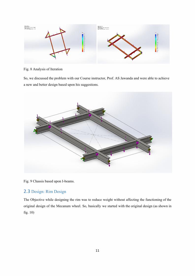
Fig. 8 Analysis of Iteration
So, we discussed the problem with our Course instructor, Prof. AS Jawanda and were able to achieve
a new and better design based upon his suggestions.
Fig. 9 Chassis based upon I-beams.
2.3 Design: Rim Design
The Objective while designing the rim was to reduce weight without affecting the functioning of the
original design of the Mecanum wheel. So, basically we started with the original design (as shown in
fig. 10)
11
Page 12
Fig.10 Original Design of Mecanum Wheel
Looking at the Fig. 10, two things were observed. First, reduce the size of the bolts connecting the
rollers to the rim & second to increase the hole diameter or merge two or more holes.
The iterations made are as shown below (Fig. 11).
Fig. 11 a) Displacement Study
12
Page 13
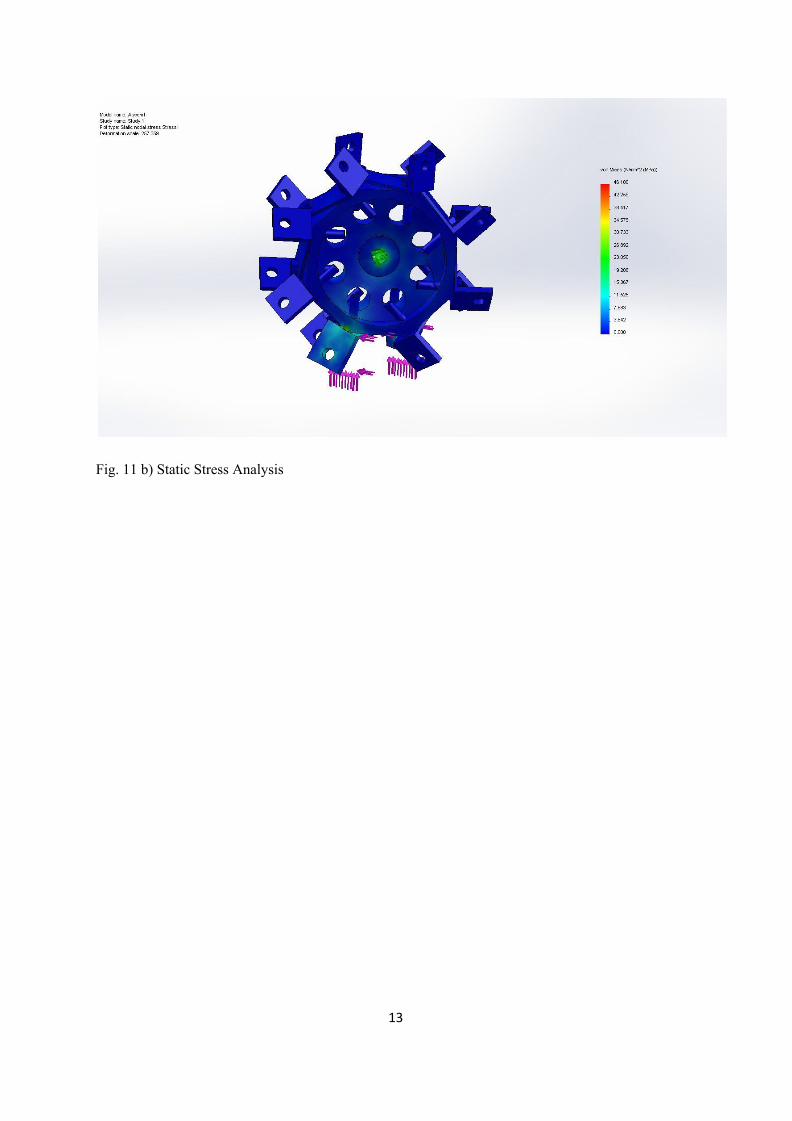
Fig. 11 b) Static Stress Analysis
13
Page 14
Fig.11 c) Modified Design Stress Analysis
So, as shown in Fig. 11 c), the modified design was obtained.
14
Page 15
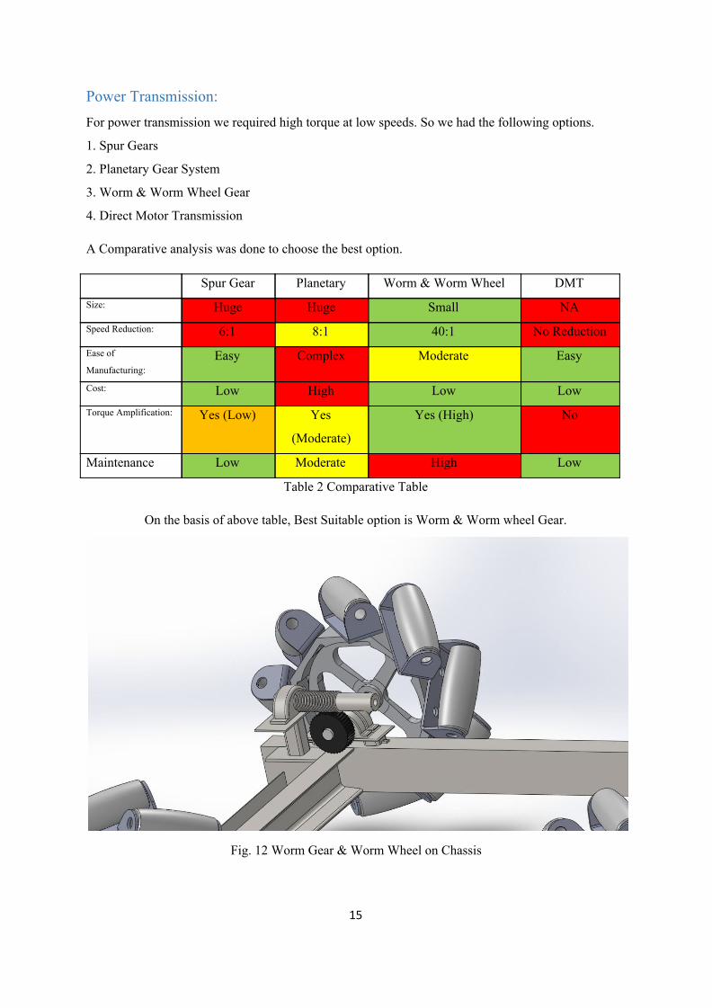
Power Transmission: For power transmission we required high torque at low speeds. So we had the following options.
1. Spur Gears
2. Planetary Gear System
3. Worm & Worm Wheel Gear
4. Direct Motor Transmission
A Comparative analysis was done to choose the best option.
Spur Gear Planetary Worm & Worm Wheel DMT Size: Huge Huge Small NA Speed Reduction: 6:1 8:1 40:1 No Reduction Ease of
Manufacturing: Easy Complex Moderate Easy
Cost: Low High Low Low Torque Amplification: Yes (Low) Yes
(Moderate)
Yes (High) No
Maintenance Low Moderate High Low
Table 2 Comparative Table
On the basis of above table, Best Suitable option is Worm & Worm wheel Gear.
Fig. 12 Worm Gear & Worm Wheel on Chassis
15
Page 16
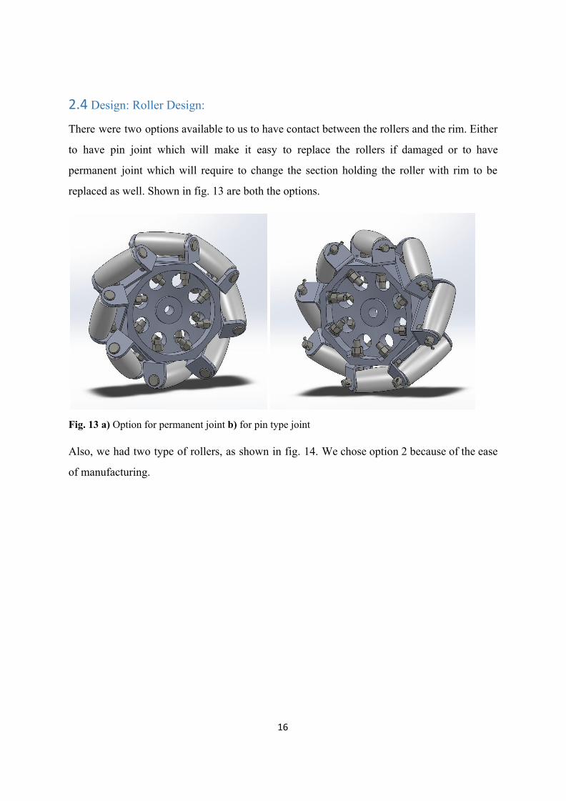
2.4 Design: Roller Design:
There were two options available to us to have contact between the rollers and the rim. Either
to have pin joint which will make it easy to replace the rollers if damaged or to have
permanent joint which will require to change the section holding the roller with rim to be
replaced as well. Shown in fig. 13 are both the options.
Fig. 13 a) Option for permanent joint b) for pin type joint
Also, we had two type of rollers, as shown in fig. 14. We chose option 2 because of the ease
of manufacturing.
16
Page 17
Fig. 14 Options for Rollers
2.5 Individual Contribution of Munish Arora
Design: Brackets
Fig. 15 Bracket designed for rollers
17
Page 18
Fig. 16 Load Analysis, Stress Analysis & FOS Simulation of Bracket
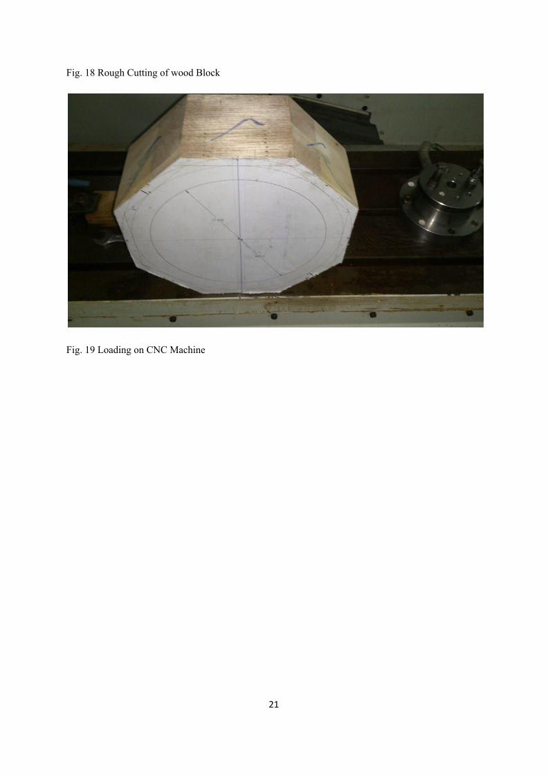
2.6 Fabrication The manufacturing of Wheel Rim. The process is as follows.
1. Pattern Development
after Purchasing the wood block, moisture content was determined before making the pattern.
After that,
Rough Cutting, Tolerances, Final Cut & Finishing was done.
18
Page 19
2. Molding Box Preparation
Mold Box was prepared.
3. Sand Preparation
Sand was first filtered for removing impurities,
then molasses was added with ratio of 1:10
Sand was mixed & finally prepared.
4. Mold Preparation
Mold was prepared & baked with blow torch (using Kerosene oil) till the core became hard.
5. Aluminium Melting
First, Aluminium chipping was done.
Then, Al was melted in furnace using coke.
Borax was added to remove slag.
6. Metal Pouring
Al was poured and the mold was kept for cooling.
7. Extraction of casting
Casting was extracted from the mold after cooling it for two days.
8. Defect Analysis
various defects were encountered during the process.
19
Page 20
Fig. 17 Wood Block used for pattern development
20
Page 21
Fig. 18 Rough Cutting of wood Block
Fig. 19 Loading on CNC Machine
21
Page 22
Fig. 20 Smoothening & Finishing of pattern.
22
Page 23
Fig. 21 Sand collected for Sand Preparation
Fig. 22 Filtering of Sand before Sand Preparation
23
Page 24
Fig. 23 Addition of molasses in sand (1:10 ratio)
Fig. 24 Mixing of Sand & Molasses; Molasses being applied inside moulding box.
24
Page 25
Fig. 25 Pattern inside mould box
Fig. 26 Preparation of mould
25
Page 26
Fig. 27 Ramming of Sand
Fig. 28 Baking of Core
26
Page 27
Fig. 29 Coke burning and Aluminium chipping
Fig. 30 Melting of Aluminium
27
Page 28
Fig. 31 heating of core after Al pouring & Breaking of hardened core after cooling.
Fig. 32 Defects occurred in casting
28
Page 29
Fig. 33 Modification in Pattern
Fig. 34 Milling Operation on Rim
29
Page 30
Fig. 35 Lathe Operation on Rim
Fig. 36 Shafts produced after turning, facing & centre-drilling operation.
30
Page 31
Fig. 37 Brackets after bending operation
Fig. 38 a) 14mm Drilling on brackets b) Drilling operation during Roller fabrication
31
Page 32
Fig. 39 wiring being done.
32
Page 33
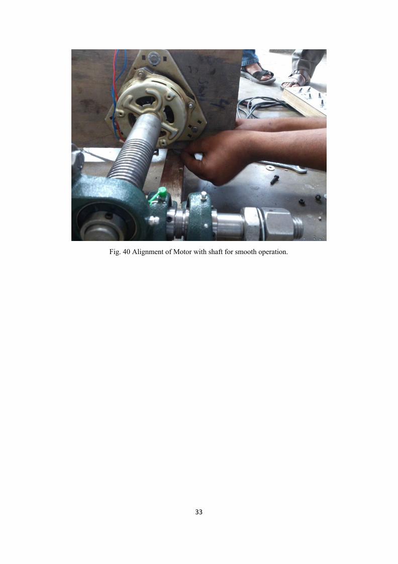
Fig. 40 Alignment of Motor with shaft for smooth operation.
33
Page 34
Fig. 41 Final Product
34
Page 35
Chapter 3 Learning:
The sole motive of this 6 months project is to give an idea what a real life application of
engineering is all about and getting first-hand experience for a market plus production
situation is definitely a thing to be proud of. During training we learnt how to identify real
life difficulties and solve them with brainstorming. The Initial brainstorming sessions were
undertook only to create an entrepreneurial skill among us all. Designing and analysis helped
us to get the hands on experience on the techniques and key-points followed for a quality
product. Real life fabrication, taking place out of this 15 inches computer screen is a real
challenge presented to us by this project.
Improvements:
1. Alloy wheel design of Rim is preferred over flywheel type
2. Rollers used are of Point contact instead of Line contact.
3. To minimize the jerk rubber tube are used.
4. Angular contact bearings UCO205 of 13 degree are installed.
Scope of future Work/Shortcomings:
1. Roller of nylon can be used for optimum performance
2. Shaft alignment
3. Motor of half hp is to be used.
4. A shock absorbing mechanism to absorb unwanted shocks.
5. If more budget is provided DC Motors can be used thus providing mobility.
35
Page 36
Overall Conclusion:
Mechanical System design course has been highly successful in imparting to us a detailed idea of how
a product is developed in industry. We, beginning from scratch and then arriving at a final product
have learnt tremendous practical concepts throughout or journey. This project has familiarized us with
the various CAD/CAE software. We now have an overview of the industrial design and are capable of
taking new initiatives. As far as the manufacturing part is concerned, we had the opportunities to use
most sophisticated as well as the most basic of machines. The understandings and learnings that came
with this were tremendous.
Apart from the common everyday ideas which were worthy of tentative projects, we counted
on various ideation techniques which would give us an idea that is a combination of
innovation, improvement, applicability as well as being able to be manufactured with given
resources. We gathered major info through internet (YouTube, Wikipedia, etc.) and looked
for recently published research papers which had a scope for MSD. Before deciding on the
project topic, we intended to tabulate the applications as well as the different populations our
project will affect. When we finalized the industrial application of Mecanum, Wheel, we
considered it for a forklift design and thus built the prototype for a capacity of 1ton.
The project is an innovation. It takes the concept of a wheel to a whole new level. This
project bears the capacity to shatter our perception that like conventional wheels, all wheels
move in just one direction. It is encouragement to budding engineers as well as researchers to
think beyond the given horizon and generate new ideas. We learnt about new materials
(majorly in plastics) like Teflon, Nylon, PVC, etc. This information was majorly banked on
our industrial exposure as well as researches carried out on the internet. Mecanum wheel is
relatively unexplored field. Due to this fact majority of the population including our teachers
are unaware of this and are oblivious to its working. This made us carry out our own research
and go through with the project.
The project has made us capable of undertaking any new innovation on our own. Although
we may need to add the fact that nothing is perfect in the first attempt and thus several
iterations are necessary to achieve the optimum result.
36
Page 37
Final Gantt chart:
Table 4 Final Gantt Chart
Brief Notes:
1. What sources of information did your group explore to arrive at the list of
problems which could be taken as the project?
Apart from the common everyday ideas which were worthy of tentative projects, we counted
on various ideation techniques which would give us an idea that is a combination of
innovation, improvement, applicability as well as being able to be manufactured with given
resources. We gathered major info through internet (YouTube, Wikipedia, etc.) and looked
for recently published research papers which had a scope for MSD.
2. How many needs were explored to form possible projects? How were the needs
analyzed to from criteria, constraints, specifications for separate project proposals?
37
Page 38
How many models (alternate designs) were considered to formulate solutions to the
need? Briefly describe them.
Before deciding on the project topic, we intended to tabulate the applications as well as the
different populations our project will affect. When we finalized the industrial application of
Mecanum, Wheel, we considered it for a forklift design and thus built the prototype for a
capacity of 1ton.
For the Mecanum wheel project we considered two separate designs but the second one fell
through in feasibility analysis due to cost and manufacturability factors.
3. What analytical, computational and/or experimental methods did your project
group use to obtain solutions to the problems in the project?
For Design problems we referred to our design course material. Worm gear and Drive was
the result of several failed reduction methodologies. We also carried out design optimizations
using CAE but still this was base level. Manufacturing problems required an upper hand in
experience which was countered with the help of Workshop Staff.
4. Did the project give an opportunity to applying mathematics learnt in earlier
courses in the form of differential equations, linear algebra, multivariate calculus,
numerical analysis, optimization, etc.? How.
Although major portions of Egg. Mathematics were not used, still we had a chance to use
optimization techniques. For future scope statistics come into picture when ergonomics of the
vehicle are taken into consideration.
5. Did the project demand demonstration of knowledge of fundamentals, scientific
and/or engineering principles? How.
Our project simple works on the principle of angular/ inclined traction force. Rollers mounted
on the wheels do this job. The drives are just through electrical motors.
6. Where did you applying scientific and/or engineering principles towards solving
problems in the project?
38
Page 39
Chassis design was the crucial area where the concepts of Twisting, Bending, etc. had to be
take into account. Loading of the chassis was done under several different conditions. The
wheels are also completely optimized under different loads like direct compression, twist etc.
Major failure criteria were analyzed for each component and the studies were carried on
further from there.
7. Was applying statistical methods in analyzing data necessary any stage in the
design, analysis, testing?
Ergonomics is the area where statistics comes into picture for our project. Anthropological
data is to be taken into account and the design for 95th percentile is carried out.
8. How did your group shares responsibility and communicate the information of
schedule with others in team to coordinate design and manufacturing dependencies.
This was majorly carried out in the MSD tutorial hors where each of the groups sat together
and shared their individual progress with the class. This is where the problems faced came to
light and synonymous solutions applied.
9. What ethical issues occurred in the course of the project work? What professional
codes of ethics were used to resolve the conflicts?
There was a major motion to get the project completed from an external mechanic/ source.
Even when majority of the groups bowed on this decision our group remained firm and
though good or bad, we still carried out each and every piece of manufacturing within the
campus workshop itself.
10. List the societal and global changes that this project may cause.
The project is an innovation. It takes the concept of a wheel to a whole new level. This
project bears the capacity to shatter our perception that like conventional wheels, all wheels
move in just one direction. It is encouragement to budding engineers as well as researchers to
think beyond the given horizon and generate new ideas.
11. What are the economics tradeoffs in your engineering design? What would be the
cost if they were not made?
39
Page 40
The foremost tradeoff will be the capacity of the drive motor. Due to budget constraints, 1/8
H.P. motor was used which is not capable of driving the vehicle under all circumstances. At
least 2 H.P. motor is mandatory and this sliver of a change would have cost us around Rs.
10000 for a set of four motors.
The other tradeoff was the material for different components like the rollers. Ideally they
would have been made of Teflon but due to cost issues we had to come down to wood itself.
12. Evaluate the environmental factors in the engineering design of this project.
Environmental factors have relatively low effect. Only consideration is the fact that this
vehicle is designed for industrial use and thus ground conditions were taken into account.
Rubber padding was thus provided to aid traction.
13. What resources did you use to learn new materials not taught in class for the course
of the project? Which of these resources, references and new learnings would you keep
for future use / anticipate would be useful in future?
We learnt about new materials (majorly in plastics) like Teflon, Nylon, PVC, etc. This
information was majorly banked on our industrial exposure as well as researches carried out
on the internet.
14. What has this project taught you about the use of self-learning? Does it prepare you
for the future to undertake new and unexplored engineering problems using
self-learning?
Mecanum wheel is relatively unexplored field. Due to this fact majority of the population
including our teachers are unaware of this and are oblivious to its working. This made us
carry out our own research and go through with the project.
Yes, the project has made us capable of undertaking any new innovation on our own.
Although we may need to add the fact that nothing is perfect in the first attempt and thus
several iterations are necessary to achieve the optimum result.
15. Does the project make you appreciate the need to solve problems in real life using
engineering?
40
Page 41
Yes. We made vehicle designed for optimum space utilization. It can work in congested
spaces, industrial environments. Hence, it is a fact that our problem solving skills have
improved.
16. What was the environmental impact, energy requirement / saving / regeneration of
your project? Did the project make you appreciate the impact of engineering decisions
on energy resources?
Our project did not skew towards the energy field. We were more concerned with automobile
aspects.
17. List the engineering equipment, hardware which this project has made you able to
use effectively?
Though the list is very long, we would still like to mention the major few.
Lathe Machine, Milling Machine, Drill Machine, CNC Lathe Machine, CNC Milling
Machine, Reciprocating Band saw, Circular band saw, Planer Machine, Press Brake machine,
Shear Bending Machine, Welding Equipment, and So on…
18. Where was programming of CNC machines, computer programming required in
the project?
We used the CNC machines to fabricate our first pattern for casting wheel rims. Circular
pockets and surfacing was done using CNC Milling machines. Photographs are attached in
the report.
19. List the software tools used to analyze engineering problems in the project.
SolidWorks2012, ProEngineer, KeyShot5, Microsoft Excel, Microsoft Word, Microsoft
PowerPoint, etc.
20. How has the project made you able to use solid modeling software for engineering
applications?
Rigorous design changes and optimizations along with simulation tools and other CAE
products have made us fluent in CAD modelling. Different special purpose modules of these
software were also used to carry out design.
41
Page 42
Chapter 4 Production and Assembly Drawings:
Fig. 42 Main Prototype
42
Page 43
Fig. 43 Final Assembly
43
Page 44
Fig. 44 Chassis
44
Page 45
Fig. 45 Wheel Rim
45
Page 46
Fig. 46 Worm Shaft
46
Page 47
Fig. 47 Worm Gear
47
Page 48
Fig. 48 Bracket
Fig. 49 Rollers
48
Page 49
Fig. 50 Dimensions of final product
49
Page 50
References
1. [O. Diegel, A. Badve, G. Bright, J. Potgieter, S. Table, 2002], Improved Mecanum
Wheel Design for Omni-directional Robots. Massey University, Auckland
2. [Samuel A. Miller, 2005], Network Interface and Fuzzy-Logic Control for A
Mecanum-wheeled Omni-Directional Robot.
3. [Florentina Adăscăliţei, Ioan Doroftei, 2011], Practical Applications for Mobile
Robots based on Mecanum Wheels - a Systematic Survey. Gh. Asachi” Technical
University of Iasi, Romania
4. [Sulabh Kumra, Rajat Saxena, Shilpa Mehta, 2012], Navigation System for
Omni-directional Automatic Guided Vehicle with Mecanum Wheel. ITM University
5. [Abdelrahman, M.; Zeidis, I.; Bondarev, O.; Adamov, B.; Becker, F.; Zimmermann,
K., 2014], A description of the dynamics of a four-wheel Mecanum mobile system as
a basis for a platform concept for special purpose vehicles for disabled persons. 58th
ILMENAU SCIENTIFIC COLLOQUIUM Technische Universität Ilmenau.
6. [Sang Won Yoon, Seong-Bae Park, and Jong Shik Kim, 2015], Kalman Filter Sensor
Fusion for Mecanum Wheeled Automated Guided Vehicle Localization. Hindwai
Publishing Corporation
50