MECH 590: Design of an Electric Aircraft with Wheel Motor-Assisted Take Off Matthew Hall September 11, 2012 Contents 1 Introduction 3 2 Electric Aircraft Design Objectives and the Green Flight Challenges 4 2.1 The Green Flight Challenge ........................... 4 2.2 Green Flight Challenge II ............................ 4 2.3 This Project .................................... 5 3 Existing Electric Aircraft 6 4 Fundamental Theory and ESTOL Design Considerations 9 4.1 Lift and Drag ................................... 10 4.2 Propulsion ..................................... 11 4.3 Range ....................................... 13 4.4 Achieving ESTOL ................................ 14 4.5 Thrust and Lift-Enhancing Approaches .................... 16 5 Power System Technologies 19 5.1 Electric Motors .................................. 19 5.2 Energy Storage .................................. 20 5.2.1 Batteries ................................. 20 5.2.2 Ultracapacitors .............................. 20 6 Design Concepts and Configuration Selection 22 6.1 Design Concepts ................................. 22 6.2 Concept Selection and Future Work ...................... 26 7 Wheel Motor Concept Development 27 1
Transcript
MECH 590: Design of an Electric Aircraft with Wheel
Air travel is a significant contributor to greenhouse gas emissions, primarily because of thetremendous quantity of travel (measured in person-km) that it enables. As well, at highaltitudes the greenhouse effect of emissions is known to be magnified. Petroleum-basedfuels have dominated the aviation industry because of their low price and excellent energydensity (energy per unit mass). In recent years, however, technology improvements inalternative energy carriers and electric motors have spurred some innovative beginnings inelectric-powered aviation.
Though no electrical energy carrier yet exists that can match the affordability and energydensity of conventional aviation fuels, the benefits of using electric motors make a promisingcase for electric-powered aircraft in some situations. Electric motors are highly efficient,so if the energy they use does not come from a particularly dirty source, they can greatlyreduce the associated emissions. They also allow the use of energy generated from non-fossil, renewable sources. Electric motors have power densities several times higher thaninternal combusion (IC) engines, and are able to maintain a high torque and efficieny acrossa wide speed range, providing potential for weight reductions and increased flexibilityin propulsion arrangement. This is particularly promising for achieving short take offand landing (STOL) performance. Electric motors are also quiet, meaning significantnoise reductions can be achieved. The potential to reduce emissions is one key benefit ofan electric power system. The other is that the potential to take off and land in shortdistances with a greatly reduced noise footprint means that electric-powered aircraft havethe potential to serve more distributed, suburban airports in a way that conventional ICengine-powered aircraft are unable to.
This report describes a research project aimed at learning at learning about the currentstate-of-the-art in electric-powered aircraft, exploring different electric aircraft design pos-sibilities, and then examining the potential of a selected electric aircraft concept through adesign optimization study. Section 2 describes the design challenges that form the basis ofthe design goals of this project. Section 3 reviews the existing electric aircraft designs andcapabilities. Section 4 looks at the basic theories applicable to modelling the performanceof electric aircraft. Chapter 5 reviews the capabilities of modern electric power systemcomponents. Chapter 6 presents a number of design concepts that aim to capitalize ondifferent advantages of electric aircraft technologies. Chapter 7 takes one of these conceptsand explores it using a design optimization study that includes a model of the aircraftflight performance using a range of power system options. Chapter 8 states the conclusionsdrawn from the project.
3
2 Electric Aircraft Design Objectives and the Green FlightChallenges
2.1 The Green Flight Challenge
The CAFE Green Flight Challenge is an effort to promote innovation in more efficient andenvironmentally-friendly air travel technologies from “non-traditional” sources - namely,not the major aerospace companies. It is one of six NASA Centennial Challenges, and it isadministered by the CAFE Foundation and sponsored by Google, and stands as the largestaviation prize ever, with a total prize amount of $ 1.6 million.
The goals of the GFC are first per-passenger efficiency and second travel speed. Additionalconstraints exist to promote a practical design and focus the competition on the generalaviation class of aircraft (no jumbo jets here). The key constraints of the GFC are:
• Range: 200 miles, with 30 min. reserve, day VFR at 4000’ MSL over non-mountainous,sparsely-populated coastal terrain
• Efficiency: 200 Passenger-MPGe energy equivalency
• Speed: 100 mph average on each of two 200 mile flights
• Minimum Speed: 52 mph in level flight without stall, power and flaps allowed
• Takeoff Distance: 2000 feet from brake release to clear a 50 foot obstacle
• Community Noise: 78 dBA at full power takeoff, measured 250 feet sideways totakeoff brake release
The score is calculated as 1/((1/mph) + (2/passenger −MPGe)) [1].
2.2 Green Flight Challenge II
A whitepaper by Brien Seeley, president of the CAFE foundation, makes the case forcontinuation of the GFC into two subsequent competitions, with a focus on developingdesigns suitable for “pocket airports” – small suburban airports that facilitate “on-demand,point-to-point air travel in quiet, small aircraft”. NASA expects this to become a significantmode of travel in the next 30 years, heralding an alternative to the inconvenience and wasteof road traffic congestion [2].
The low noise and short take off and landing requirements of such pocket airports bothpoint to electric power systems as the necessary propulsion technology for this new industry.With the “innovator’s dilemma” that makes it difficult for the major aerospace players towant to invest in potentially-disruptive and small-market technologies, Sealy contends that
4
continuation of the Green Flight Challenge is the logical way to support the growth of ahighly-efficient small aircraft industry to support the pocket airport concept. The GFCII challenge he proposed focus first on the noise and STOL requirements of such airports.Details of a third GFC challenge, which would then focus on the navigation and safetyrequirements of having a dense network of air traffic that comes with these pocket airports,are by in large separate from the flight performance of an electric aircraft, and are thereforenot of interest in this electric power system project.
The GFC II would keep the constraints of the original GFC, and add additional require-ments for compatibility with small urban pocket airports. The key short takeoff/landingand noise constraints are recommended to be:
• Takeoff Distance: 400 feet from brake release to clear a 50 foot obstacle
• Community Noise: 60 dBA at full power takeoff, measured 125 feet sideways totakeoff brake release
2.3 This Project
These constraints – those of the GFC and the recommended ones for a GFC II – formthe performance objectives for my aircraft design project. In addition, the aircraft designwill be required to carry four to six people (as a reasonably number for an aircraft usefulfor more than individual transportation) and special emphasis will be put on economicand technical feasibility (to support the intention that this could eventually develop intoan impressive demonstration of electric-powered general aviation). With these objectivesadhered to, the primary finding of this work beyond just the design developed will be thecost – how cheaply these objectives can be met. The assembled set of design objectivesare:
• Range: 200 miles, with 30 min. reserve, day VFR at 4000’ MSL over non-mountainous,sparsely-populated coastal terrain
• Efficiency: 200 Passenger-MPGe energy equivalency
• Speed: 100 mph average on each of two 200 mile flights
• Minimum Speed: 52 mph in level flight without stall, power and flaps allowed
• Takeoff Distance: 400 feet from brake release to clear a 50 foot obstacle (same forlanding)
• Community Noise: 60 dBA at full power takeoff, measured 125 feet sideways totakeoff brake release
• Occupancy: 4-6 adults
5
3 Existing Electric Aircraft
A number of successful manned electric-powered aircraft have been designed and built inthe last ten or so years. This section describes some of the most notable cases.
Lange Aviation Antares 20E
The Antares 20E (Figure 1), an electric motor glider, is perhaps the most establishedelectric aircraft on the market, having been produced for almost ten years. It is a single-person sailplane with a retractable motor mounted on a pylon above the fuselage turninga two-bladed 2 m propeller. It has a purpose-built 42 kW brushless outrunner electricmotor powered by a lithium ion battery pack with a capacity of about 10 kWh [3]. Thoughdesigned for gliding rather than commuting, this design demonstrates the possibilities foraerodynamic efficiency with a retractable electric system.
Figure 1: Antares 20E
Yuneec e430
The Yuneec e430 (Figure 2) is a two-seater design with a highly efficient layout (24:1 glideratio) and a V tail. It features a 40 kW motor brushless outrunner motor and a lithiumpolymer battery system, both manufactured by Yuneec. It has won several prizes includingthe Lindberg Prize for Electric Aviation at the 2010 Oshkosh Air Show [4].
Pipestral Taurus G2/G4
The Taurus Electro G2 (Figure 3) is a two-person motor-glider design adapted to use aretracting electric motor and propellor, similarly to the Antares 20E.
6
Figure 2: Yuneec e430
Figure 3: Taurus G2
The Taurus G4 (Figure 4) is a unique four-person aircraft designed specifically to win theGreen Flight Challenge, which it succeeded in doing! It features twin Taurus G2 fuselagesand tails, with Taurus G2 wings on the outsides and a thicker wing section joining the twofuselages together and supporting a central engine nacelle, which houses a 145 kW motorand a lithium polymer battery system [5].
University of Stuttgart E-Genius
The E-Genius (Figure 5) is a two-person design that looks like a high-wing sailplane, buthas an electric motor and propellor mounted at the top of the vertical stabilizer. It sharesmany similarities to the Antares E20 or Taurus G2, however the more aerodynamic non-retracting motor installation on the vertical stabilizer makes for more efficient powered
7
Figure 4: Taurus G4 - GFC winner
flight [6]. Like the Taurus G4, it was designed for the Green Flight Challenge, and it camein second place, very close behind the Taurus G4 in both speed and efficiency categories[7].
Figure 5: University of Stuttgart E-Genius
8
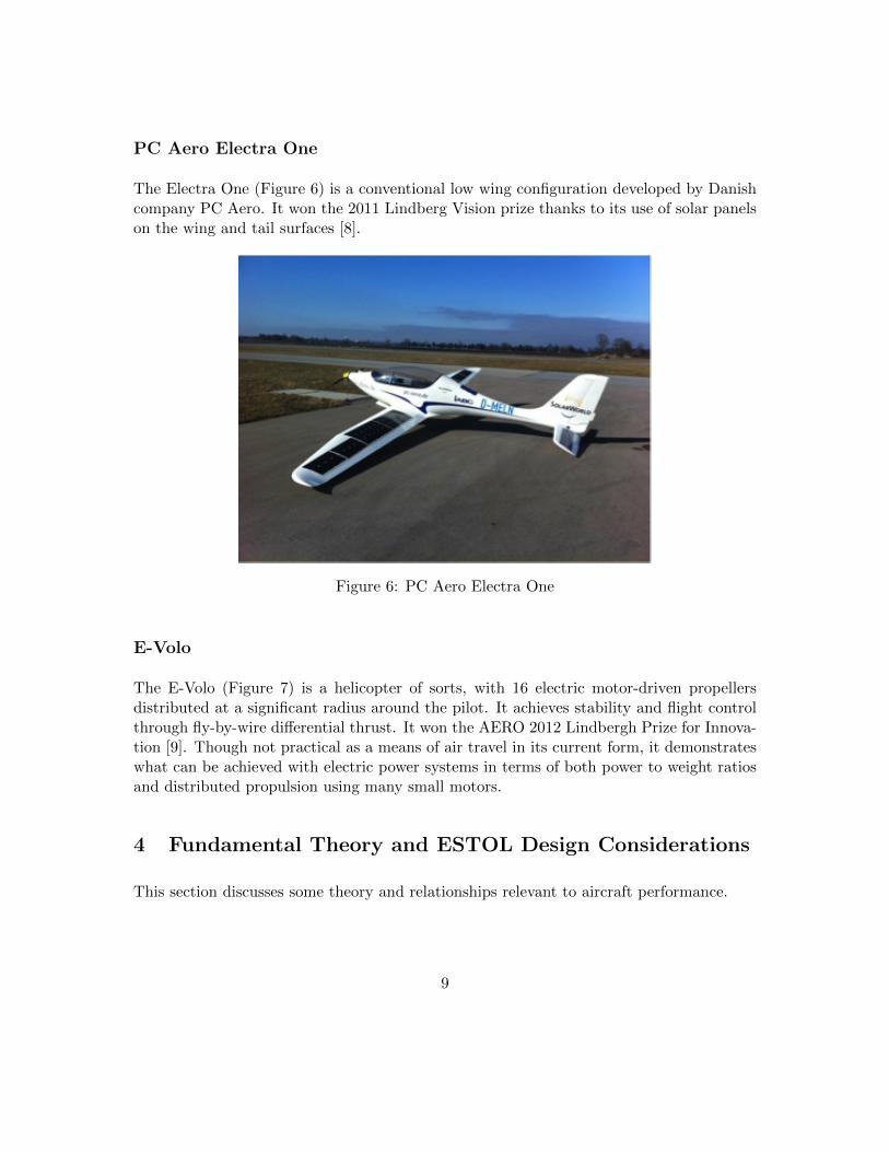
PC Aero Electra One
The Electra One (Figure 6) is a conventional low wing configuration developed by Danishcompany PC Aero. It won the 2011 Lindberg Vision prize thanks to its use of solar panelson the wing and tail surfaces [8].
Figure 6: PC Aero Electra One
E-Volo
The E-Volo (Figure 7) is a helicopter of sorts, with 16 electric motor-driven propellersdistributed at a significant radius around the pilot. It achieves stability and flight controlthrough fly-by-wire differential thrust. It won the AERO 2012 Lindbergh Prize for Innova-tion [9]. Though not practical as a means of air travel in its current form, it demonstrateswhat can be achieved with electric power systems in terms of both power to weight ratiosand distributed propulsion using many small motors.
4 Fundamental Theory and ESTOL Design Considerations
This section discusses some theory and relationships relevant to aircraft performance.
9
Figure 7: E-Volo
4.1 Lift and Drag
Lift and drag forces can be expressed as functions of air density, ρ, flight speed, V , andwing area, S, by using the lift and drag equations:
L = 1/2CLρV2S (1)
D = 1/2CDρV2S (2)
where CL and CD are the lift and drag coefficients - aerodynamic properties of the aircraftand its flight surfaces. Aerodynamic efficiency can then be expresses as the ratio of liftcoefficient to drag coefficient.
Airfoils have well-known lift and drag coefficients, and this lift to drag ratio can be readdirectly off airfoil polar plots. However, additional lift and drag effects from other partsof the aircraft and the finite length of the wings must be taken into account before theoverall lift-drag of the aircraft is obtained. Spanwise flow along the wings caused by thecirculation of trailing wingtip vortices leads to an additional drag force, induced drag. The“tip leakage” around the wing tips, also a result of trailing vortices, causes a reduction inlift.
The simplest ways of approximating these effects make use of the wing’s aspect ratio, AR.The lift coefficient can be adjusted for tip leakage using:
10
CL =CL(airfoil)
1 + 2/AR(3)
And the induced drag coefficient to be added to the overall drag coefficient is:
CDi =C2L
πARe(4)
where e is the Oswald efficiency factor, which can be approximated as:
e = 1 − 0.045A0.68R (5)
Looking at these equations a high aspect ratio can be seen to both increase lift and reducedrag.
4.2 Propulsion
Momentum theory provides some useful relations between an aircraft’s airspeed, V , theswept area of the propeller, Ap, the speed of the propeller jet relative to the aircraft, Vj ,the thrust, F , the propulsive power, Pj , and the shaft power, Pshaft.
The thrust is calculated from the change in energy or change in momentum of the airthrough the propeller disk:
F =1
2ρAp(V
2j − V 2) (6)
F = m(Vj − V ) (7)
Incidentally, combining (6) and (7) shows that the speed through the disk is (V + Vj)/2.Multiplication by V then gives the propulsive power - the power going into propelling theaircraft.
Pprop = FV = mV (Vj − V ) (8)
The mechanical “shaft” power of the propeller is found from the kinetic energy added tothe air [10]:
Pshaft =1
2m(V 2
j − V 2) =1
4ρAp(V + Vj)(V
2j − V 2) (9)
11
The propulsive efficiency is then:
ηp =Pprop
Pshaft=
mV (Vj − V )
(1/2)m(V 2j − V 2)
=2V
V + Vj=
2
1 + Vj/V(10)
Solving (6) for Vj and substituting into (9) gives an expression for the engine power as afunction of thrust, swept area, and airspeed:
Pshaft =1
2F
(V +
√2F
ρA+ V 2
)(11)
This expression, which is independent of jet speed, will be useful for calculating the powerrequirements associated with different propeller sizes.
The rotation of the propeller blades must also be taken into account when calculating thepower required to turn the propeller. The shaft power is the product of torque and angularspeed: Pshaft = ωQ = 2πnQ where Q is torque. Based on the propeller operation, thisshaft power can be calculed as [11]:
Pshaft = CPρn3D5 (12)
and the thrust is:
T = CTρn2D4 (13)
where n is angular speed, D is propeller diameter, and CP and CT are power and thrustcoefficient, which can be measured for a given propellor at a given advance ratio. Advanceratio is calculated as J = V/(nD) and is analagous to the tip speed ratio in wind turbinetheory.
Figure 8 shows the propellor efficiency versus advance ratio, calculated for a number offixed blade pitches [11]. Figure 9 shows a similar plot for propeller thrust coefficient [11].These figures show how for a given pitch, a propellor has a single point of peak efficiencyand that beyond that point (as the advance ratio increases) its ability to produce thrustdecreases rapidly.
Looking at Figure 9, (13), and the exponents of n and D in (12), it can be deduced that ahighly-pitched, quickly-turning propeller is necessary for efficient high-speed flight, whilea low-pitch, slowly-turning, large-diameter propeller is most efficient for low speed flight.
12
Figure 8: Propellor efficiency vs. advance ratio [11]
Figure 9: Propellor thrust vs. advance ratio [11]
Variable-pitch propellers, which operate at nearly constant rotation speeds, improve theefficiency at both high and low flight speeds. However, constant propeller diameter is ahindrance to further efficiency gains across the range of flight speeds.
4.3 Range
For a conventional fuel-burning aircraft, the range calculation takes into account the non-constant weight of the aircraft as it burns fuel. The instantaneous range is:
13
dR
dW=
V
−CT=
V
−CW (D/L)(14)
where R is range, W is weight, and C is specific fuel consumption (fuel weight rate ofchange divided by thrust). Integrating gives the Breguet range equation, which can besimplified if velocity, lift-drag ratio, and specific fuel consumption are constant [12]:
R =
∫ wf
wi
V (L/D)
−CWdW =
V
C
L
DlnWi
Wf(15)
For a power system where the weight change is not significant, the range needs to becalculated differently (again using T = WD/L):
R = VEc
E= V
Ec
TV/ηP=
1
W
L
DηPEc (16)
where Ec is the energy storage capacity, dotE is the power consumption, and ηP is thepropulsive efficiency.
4.4 Achieving ESTOL
Designs have proven than electric aircraft can be feasible in terms of speed and handling,with a limited but usable range, and with a gas-powered generator in a hybrid configuration,can provide almost standard ranges. The 400 ft takeoff run expected in the GFC II howeverexceeds the abilities of all the aircract listed previously.
It is prudent then to explore the various way in which this ESTOL performance could beachieved
The 400 ft takeoff requirement can first be explored in a very simplified way for a conven-tional takeoff technique (where lift comes almost exclusively from the wings). The thrustrequirement can be calculated for a given overall lift ability (or CLS), and aircraft weight(m/g). This is a very preliminary analysis, because it considers only the ground roll portionof takeoff, and neglects the transition period and the 50-ft obstacle clearance requirement.Also in the plots the follow the approximation S = CLS in (18) is used on the groundsthat for such a short takeoff distance the inertial forces dominate the drag forces. As such,this approach is approximate and underestimates the thrust required.
dg =
∫ Vf
Vi
V
adV =
1
2
∫ Vf
Vi
1
ad(V 2) (17)
14
a = F/m =T −D − µ(W − L)
m=T −mgµ+ 1/2ρS(µCL − CD0 −KC2
L)V 2
m(18)
Solving the integral of (17) yields:
dg =m
2KAln
(KT +KAV
2F
KT +KAV 2i
)(19)
where KT = T −mgµ and KA = 1/2ρS(µCL − CD0 −KC2L).
Using this equation, the average thrust required during the takeoff roll for transition at400 ft, as a function of aircraft mass and lifting ability (CLS), is plotted in Figure 10.An intermediate variable, and an important parameter in itself, is the required speed attakeoff, shown in Figure 11.
510
1520
2530
0
0.5
1
1.5
2
x 104
0
10
20
30
40
50
60
CLS (m
2)
m (kg)
T (
kN
)
Figure 10: Thrust required for 400 ft ground roll, according to (17)
These plots show the intuitive increase in takeoff speed and thrust required with increasingweight and with decreasing lifting ability. Not surprisingly, a lighter aircraft with a highlift capability is desireable due to reducing the thrust requirements. Several constraintscome into play at this point:
• the structural limits on light wing loadings (you can only make a wing so light beforeit becomes too fragile)
• the payload requirements (obiously the payload must be included in the mass, andthe required strength to carry the payload has a significant mass)
• the speed objectives of an aircraft (too light a wing loading will result in an aircraftwith a very low cruise speed)
15
510
1520
2530
0
0.5
1
1.5
2
x 104
0
20
40
60
80
100
CLS (m
2)
m (kg)
VT
O (
m/s
)
Figure 11: Takeoff velocity for 400 ft ground roll, according to (17)
The relationships defining these constraints will need to estimated, after which they can beadded to Figure 10 to further define the design space for conventional lifting configurations.
The calculation of the energy required for take off requires prior specification of the propul-sion system and its efficiency. However, the kinetic energy required ino accelerating theaircraft to take off speed is simply the product of the thrust force times the ground rolldistance. This can be visualized by multiplying the thrust axis in Figure 10 by 121.9 m(400 ft).
It is important to remember that short landing is an equally-important criterion for theaircraft design. Having a very high thrust capability may be enable short take off butcontribute nothing to short landing abilities. While powerful aerodynamic braking capa-bilities or even the use of runway-mounted arresting gear such as used on aircraft carriersare a means to achieve short landing distances without low speed flight, there a numberof practical and safety-related reasons why these approaches are not desirable for generalaviation. Therefore, slow-speed flight is an essential part of the short landing design objec-tive. In many cases, propulsion and high-lift go hand-in-hand, as is discussed in the nextsection.
4.5 Thrust and Lift-Enhancing Approaches
There are a number of special techniques that can be used to achieve the high thrustrequired for short take offs, to achieve the high lift required for short take offs and landings,or in some cases to achieve a combination of both.
16
Folding Propellers
Folding propellers are common for powered radio-control gliders, and are now being usedon full scale motor gliders. A folding propellor features blades that are hinged so that theyare free to pivot in the flapwise direction. When they are turning, centripetal accelerationholds the blades at the correct angle, when the motor stops, springs or air drag fold thepropellor blades back into a streamlined shape. An example of a folding propellor systemfor electric aircraft is shown in Figure 12 [13]:
Figure 12: Front Electric Sustainer folding propeller
Some motor gliders take the fold propeller idea a step further, retracting the entire propellerand motor assembly into the back of the aircraft. The use of propellers for takeoff that foldduring cruise is one possibility for achieving boosted take off power without the efficiencypenalty of additional propellers operating during flight.
Tilt-Rotor / Vectored Thrust
For aircraft with high thrust-to-weight ratios, the thrust of the engines can be used directlyto contribute to carrying the weight of the aircraft. This is done by tilting the propellerrotor in an upward direction, mimicking the operation of a helicopter. The goal is usuallypurely-vertical take off and landing (VTOL). Some aircraft (such as the V22 Osprey) pivotthe propellers from facing forward to facing up. Others, such as gyrocopters and the F-22, feature an upward facing propeller/impeller that is seperate from the forward thrustengine.
17
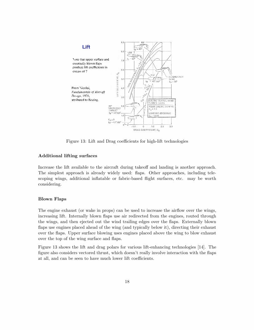
Figure 13: Lift and Drag coefficients for high-lift technologies
Additional lifting surfaces
Increase the lift available to the aircraft during takeoff and landing is another approach.The simplest approach is already widely used: flaps. Other approaches, including tele-scoping wings, additional inflatable or fabric-based flight surfaces, etc. may be worthconsidering.
Blown Flaps
The engine exhaust (or wake in props) can be used to increase the airflow over the wings,increasing lift. Internally blown flaps use air redirected from the engines, routed throughthe wings, and then ejected out the wind trailing edges over the flaps. Externally blownflaps use engines placed ahead of the wing (and typically below it), directing their exhaustover the flaps. Upper surface blowing uses engines placed above the wing to blow exhaustover the top of the wing surface and flaps.
Figure 13 shows the lift and drag polars for various lift-enhancing technologies [14]. Thefigure also considers vectored thrust, which doesn’t really involve interaction with the flapsat all, and can be seen to have much lower lift coefficients.
18
Jet Assisted Take Off
Jet-assisted take off (JATO) is a technique used by military aircraft such as the C-130 toboost the thrust of the aircraft to take off from very short runways via rocket engines.Though the high fuel consumption of this approach makes it unadvisable for a ”Green”Flight Challenge contender, the concept of additional sources of thrust used for takeoffmay prove relevent with the application of other thrust sources.
Wheel Motors
The high powers and torques of external rotor brushless motors has encouraged the devel-opment of “wheel motors”, electric drive motors for vehicles that actually fit within thewheels. For ESTOL electric aircraft where the greatest power requirements is for takeoff,using wheel motors to provide the majority of takeoff acceleration may in fact be a morepractical approach than. They also provide the opportunity for regenerative braking duringlanding.
Towing
Lastly, there is the means by which many unpowered gliders become airborn - being towedby a rope (with either a vehicle, aircraft, or winch system at the other end). While thisapproach is proven effective for gliders, it may be impractical for general aviation uses, orfor requiring tow facilities at airports that do not already have them.
5 Power System Technologies
5.1 Electric Motors
With no previous market for electric airplane motors, there is no well-established generalaviation electric motor industry. However, a closely-related industry has been developingthe sort of light, powerful, slow-turning electric motors needed for some time - the hobbyradio-control aircraft industry. The use of specialized motors for radio control planes isquite well-established, with a high level of convergence to a single motor technology: theexternal rotor brushless motor.
Brushless motors use permanent magnets on the rotor and electrical commutation to avoidthe friction and electrical inefficiency associated with the use of brushes in conventionalDC motors. The motor controller provides an alternating current to the electromagnets
19
of the stator, providing a high degree of control over the motor operation. Advantages inefficiency, cost, and reliability can be gained by designing the motor with a high torque andlow speed such that it can turn a propeller directly rather than using a gearbox. Externalrotor (or “outrunner”) motors were designed for this purpose. As the name implies, therotor in these motors is located on the outside of the stator. Because the rotor is quitethin radially (only containing permanent magnets) while the stator is thicker (containingelectromagnets) an external rotor provides a significantly larger radius/circumference ofthe magnet gap, allowing a greater number of poles in the motor, increasing the motortorque and making it well-suited for lower-speed operation.
These designs have been used in the hobby R/C plane market for many years, and achievehigh efficiencies on the order of 95%. They also provide extremely high power to weightratios of up to 7 kW/kg, require no gearbox, and are produced with power outputs of up to15 kW. These sizes make some hobby motors suited for manned aircraft as-is. A number ofpurpose-built electric aircraft motor lines now exist, that basically expand the capabilitiesof their hobby-level ancestors, with power outputs of up to 145 kW.
5.2 Energy Storage
5.2.1 Batteries
Lithium ion batteries seem to be the choice for all the aircraft listed above. They offerenergy densities of around 100 Wh/kg and power densities of around 100-1000 W/kg [15].It is their high energy density that makes them the prefered choice for powering aircraft.Their power density can be a limiting factor, and a tradeoff has to be made between acell optimized for energy density of for power density when choosing the batteries to use.SAFT is one of the main battery manufacturers, and their cells are used in the Antares20E. Figure 14 plots the power and energy densities for the SAFT lithium ion cells thatcould be used.
5.2.2 Ultracapacitors
Ultracapacitors, while inferior to lithium ion batteries in energy density, have value in theirextremely high power density. Modern ultracapacitors have energy densities on the orderof 4 Wh/kg and power densities on the order of 1000 W/kg [burke]. As with batteries,there is a tradeoff between energy density and power density. A plot showing this tradeofffor an ultracapacitor recently unveiled by Honda for use with its latest fuel cell cars [16] isgiven in Figure 15.
These characteristics make ultracapacitors useful for high-power, short-duration energy
20
0 2 4 6 8 10 12 14 1650
100
150
200
Power density (kW/kg)
En
erg
y d
ensity (
kW
h/k
g)
cell data
fit
Figure 14: Power and energy densities for various SAFT lithium polymer cells
Figure 15: Performance of ultracapacitors according to Honda
demands (such as for buffering in a fuel cell car). Whether there is a use for them inaircraft, which tend to have relatively steady energy demands (even the power throughoutthe takeoff is relatively constant), remains to be seen. Potential exists for synergies betweenthis short power burst potential and the ability of electric motors to vastly increase theirpower output for very short durations (overheating being the limiting factor).
21
6 Design Concepts and Configuration Selection
This section presents a number of concepts for aircraft configurations that could potentiallymeet the design requirements. The common feature of all of these is that electric motorsare an integral part of the design. Whether these concepts would be pure electric or hybridelectric is a secondary consideration, as in most cases either power approach is attainablewith only small changes to the aerodynamic and propulsive configuration.
The main exception is with a “through the air” parallel hybrid approach, in which one ormore propellers are IC engine-driven and one more propellers are electric motor-driven;the approach could require more significant modifications to the configuration and not bepossible with some configurations. Such an approach could include a very small generatorattached to the IC engine to charge the electric power system over the course of a flightin preperation for landing or the next take off. The applicability of the through the airparallel hybrid approach will be noted for applicable configurations.
From a qualitative comparison of the characteristics of each configuration, a configurationswill be selected for continued study and design optimization.
6.1 Design Concepts
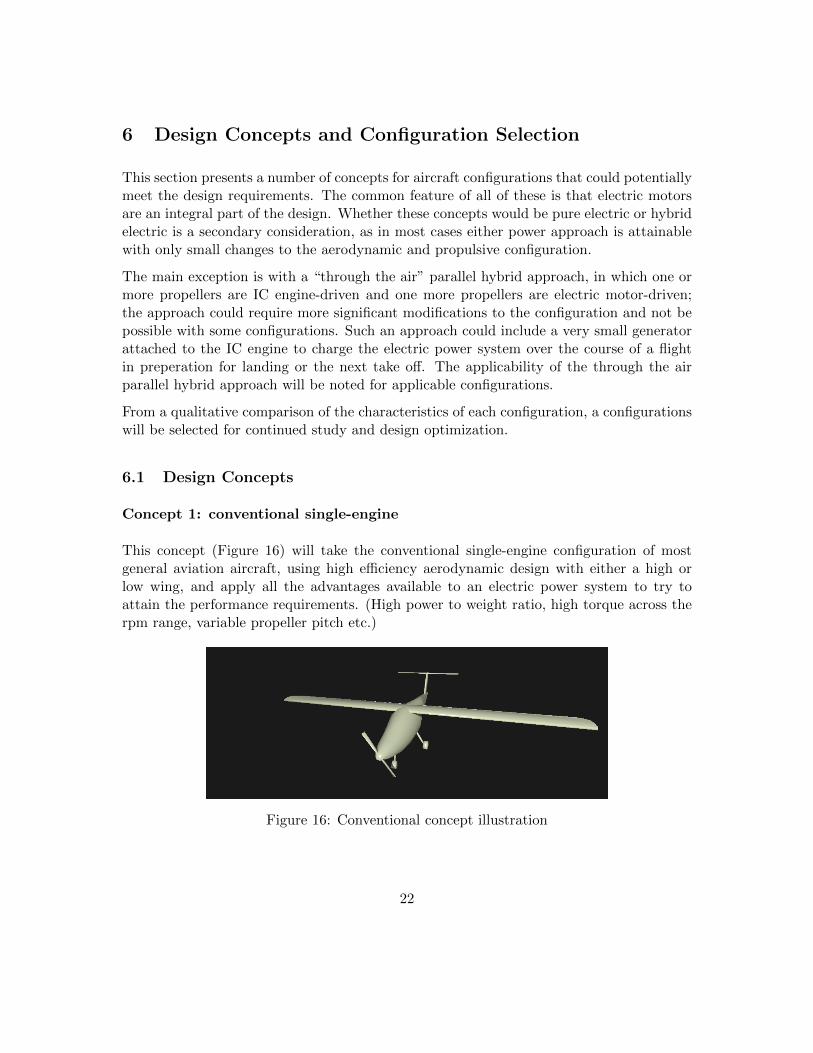
Concept 1: conventional single-engine
This concept (Figure 16) will take the conventional single-engine configuration of mostgeneral aviation aircraft, using high efficiency aerodynamic design with either a high orlow wing, and apply all the advantages available to an electric power system to try toattain the performance requirements. (High power to weight ratio, high torque across therpm range, variable propeller pitch etc.)
Figure 16: Conventional concept illustration
22
Concept 2: canard pusher
This concept (Figure 17) is similar to the previous one, but uses a canard configurationwith a pusher propeller, for potentially improved aerodynamic efficiency.
Figure 17: Canard pusher concept illustration
Concept 3: large-propeller pusher
This concept tries to achieve the biggest propeller size for a single propeller configuration.A pusher configuration is used to allow a higher propeller mounting location (withoutobstructing visibility). To keep the propeller near the CG to avoid ground contact duringtake off and landing rotation, a canard configuration is not used. Rather, a twin tailconfiguration coming from booms on either wing provides stability, while keeping the tailsurfaces out of the prop wash to reduce drag.
This concept uses a relatively conventional aerodynamic configuration but addes wheelmotors in the main landing gear to boost take off acceleration. A risk in this approach isthat the wheel motors result in the aircraft “doing a wheely” or other contrall issues fromloss of traction to either wheel; therefore, the choice of configuration is partially dictatedby these concerns. A tractor canard configuration with a conventional vertical tail providesprop wash on all the flight control surface, improving maneuverability and control at lowspeeds. The canard also provides a powerful down-pitching moment required to combatthe “wheely” risk, and in doing so it provides a downward force (rather than the upwardforce of a conventional elevator) increase the normal force and traction available to thewheels. (Also, with the further-aft location of the wheels to prevent wheelying, an elevatorwould have to provide a very large down force to pitch the aircraft up during rotation.)
This concept will feature two propellers - one tractor and one pusher - and a canard wingconfiguration. The pusher propeller and motor will be sized to provide the most efficientcruise performance. The front propeller will be larger than the rear propeller and alongwith its motor will be designed to provide high thrust for take off. It will fold duringcruise operation. In this way, a high rotor plane area for efficient takeoff thrust but alower rotor plane area for higher-speed cruise is achieved. Also, during the lower airspeedsof takeoff, the lower speed of the front propeller will act to pre-accelerate the air for thehigher-speed pusher propeller, increasing the efficiency of the pusher propeller. All thisavoids the complexity of variable-pitch propellers.
If the rear motor was replaced with an IC engine, this configuration could be well suitedto a through the air parallel hybrid power system.
24
Figure 20: Tractor-pusher concept illustration
Concept 6: quad tilt rotor
This concept uses a canard or tandem wing configuration, and features four or more motor-propeller combinations distributed between the wings. Either the rotors will pivot tovertical to provide vertical takeoff or the entire wings and rotors will pivot together toprovide vertical or extremely short takeoff and landing. The use of four or more rotorsprovides a high degree of control without the complexity of cyclic pitch control. The strongESTOL/VTOL benefits of this configuration are balanced by potentially defficiencies incruise efficiency and the risk of losing lift due to entering a vortex ring state, as has occuredwith the V-22 Osprey tiltrotor.
Figure 21: Quad tilt rotor concept illustration
Concept 7: blown wings
This concept uses a number of small motor-propeller combinations situated in front of thewings to make the majority of the wing surface in propwash during take off and landing.Combining high-lift slotted flaps along the wings, this “blown flap” effect makes for veryhigh lift coefficients, enabling ESTOL performance. The large number of rotors makes for
25
a large combined rotor disc area which improves the low speed thrust needed for takeoff. Acanard configuration, with two propellers mounted ahead of the canard, provides the easiestway of keeping all control surfaces in prop wash, essential for low speed maneuverability.A single larger drive motor and propeller will be mounted at the fuselage aft as a pusherfor cruise, or the two inboard motor-propellers on the main wing will be used for cruise.The remaining motors will be stopped and the propellers folded during cruise for greaterspeed and efficiency.
Using an IC engine to drive the main pusher propeller, this design could be suited for aparallel through the air hybrid power system.
Figure 22: Blown wings concept illustration
6.2 Concept Selection and Future Work
The anticipated strengths and weaknesses of the seven design concepts are compared in sixdifferent categories (take off, climb, cruise, landing, serial hybrid, parallel hybrid) in Table1. These categories represent: the ability to achieve sufficient lift within the required takeoff distance, climb performance, the ability to cruise at a high speed with high efficiency, theability to fly slowly and land within the required distance, the potential for implementinga serial hybrid system, and the potential to instead convert the propulsion system to aparallel “through the air” arrangement, respectively.
In the decision matrix, Concept 7 (the blown wing design) comes out on top, followed bythe Concepts 5 (the tractor-pusher design), 4 (the wheel motor-equipped design), and 6(the quad tilt rotor design).
Concept 7’s augmented lift capability and large combined rotor plane area make for goodlow-speed performance and good acceleration and climb performance. Folding of the ma-jority of the propellers allows fast and efficient cruise performance as well. The optionto use of a single pusher propeller for cruise opens up some interesting possibilities for aparallel hybrid power system for achieving extended range.
26
Table 1: Design Concept Decision Matrix
# name take off climb cruise landing serial hybrid parallel hybrid total score
Though it came in third place in the matrix, Concept 4 is the one selected for furtherstudy. The idea of using wheel motors to boost take off acceleration is too interesting topass up! Furthermore, the design makes good use of the high power-to-weight ratios ofelectric motors and is conducive to a parallel hybrid configuration.
7 Wheel Motor Concept Development
The wheel motor concept was chosen for further exploration, as both an interesting conceptand one that is easily analyzed. Looking into it, it became obvious that the concern of”wheelying” that had prompted the canard configuration shown in Figure 19 was a non-issue; the main landing gear could be easily located far enough behind the center of gravityso that the wheels would lose traction before causing pitching of the aircraft. It alsobecame apparent that to meet the ambitious ESTOL performance targets with the powerdensities of existing motors and still have the required cruise speed, a very large propellerarea would be required. To still use only one propeller, the airframe configuration wastherefore switched to that shown in Figure 18, which allows a very large propeller. Thisconfiguration has a number of additional benefits by virtue of its tail-supporting pylons onthe wings, which provide:
• a convenient structural for supporting the high loads of the power main landing gear,and housing them when they are retracted
• a location for locating the heavy battery packs, that provides ample space for thingslike cooling systems, and also helps distribute the mass across the wing span, reducingthe structural requirements on the wings
• convenient locations for mounting folding propellers for use in the ”through-the-road”hybrid power system configuration. This configuration is illustrated in Figure 23.
27
Figure 23: Final concept illustration, with additional folding propellers for “through-the-air” hybrid configuration
The first order of business is discovering the behaviour of wheel motor-assisted takeoff incombination with a suitable power system and takeoff strategy. Emphasis is placed on theoptimal utilization of the wheel motor technology for ESTOL performance rather than onthe aerodynamics of the aircraft. Therefore, with the exception of the use of a slightlyunusual aerodynamic configuration for allowing larger propeller sizes, the aerodynamics ofthe aircraft are assumed to be relatively standard for a high-performance design, equivalentto other aircraft used in the GFC.
7.0.1 Airframe Assumptions
Before exploring the power system and takeoff strategy optinos for wheel motor-assistedtakeoff, some generic airframe constants need to be defined. These can be refined later,after the optimal power system has been determined.
Weight is a major factor in the power system sizing. As the weights of all the power systemcomponents are variables in the analysis, the weight of the aircraft excluding the powersystem needs to be defined seperately. This weight is assumed constant in this analysis,and is set to the sum of the payload weight (90 kg * 4 passengers) and the weight of theaircraft structure (estimated to be 300 kg, based on some weight information for similarelectric aircraft).
A high lift coefficient is a crucial requirement for ESTOL performance without eitherextreme accelerations, impractically-light wing loadings or powered lift. The desire to keepthe airframe relatively conventional and focus on the innovative use of wheel motors for
28
Figure 24: Polar plot of GAW-2 airfoil with single-slotted fowler flaps
the design concept means that conventional high-lift devices - namely, flaps - are the wayto go. Single-slotted fowler flaps were chosen. These take the very high lift ability of fowlerflaps but avoid the complexity of multi-slotted flaps as found on larger aircraft.
The choice of airfoil was guided by the desire for a reputable high-performance low-speedairfoil, and the practical necessity of finding an airfoil for which fowler flap polar data wasavailable. The GAW-2 proved to be such an airfoil. Extensive wind tunnel data on it,including with control surfaces and fowler flaps, is available in [17]. The polar plot fromwhich the airfoil lift and drag coefficients used in the analyses are taken is shown in Figure24.
The choice of wing planform for lift and drag calculations was made based on existinghigh-efficiency electric aircraft designs. The aspect ratio was chosen to be 20, which gives ahigh Oswalde efficiency factor assuming a rectangular wing planform. After experimentingwith difference empirical models, a drag coefficient for the fuselage and all other non-wingfeatures was chosen such that the overall glide ratio of the aircraft matches that of amiddle-range-efficiency electric aircraft, the Yuneec E-430, at 25:1 [4]. Again, these choicesare intended to give a reasonable representation of a typical high-efficiency airframe.
7.0.2 Propeller Model
The propeller is modelled using power and thrust curves taken from [18]. The choice ofpropeller is dictated by two constraints.
29
The first constraint relates to the low noise objectives of the project. According to [2], tomeet the 60 dBA noise constraint, the propeller tip speeds must be under 400 ft/s (122m/s). With a desired cruise speed of 45 m/s, an advance ratio of 1.5 is suitable to keepthe propeller tip speeds within the constraints (from the equation defining advance ratio).For simplicity and weight savings, and with the wheel motors to provide extra accelerationduring the ground roll, a fixed-pitch propeller is assumed. According to the curves in[18], the propeller pitch that gives the greatest efficiency at an advance ratio of 1.5 (as isexpected at cruise) is 35 degrees.
The second constraint relates to the size of the propeller. The aspect ratio of the propelleris kept fixed because the focus of the work is not on propeller design, so the remainingvariable most affecting the propeller’s ability to efficiently produce thrust is it’s diameter.With the limitations of the modelling approach used, larger propeller diameters are alwaysmore efficient. The upper limit on propeller diameter comes from the ground clearanceneeded. Therefore, the propeller diameter is assumed to be the maximum permissiblediameter within this constraint. This is taken to be 3 m for the main propeller and 2m for the additional pylon-mounted propellers in the ”parallel through-the-air hybrid”configuration.
7.0.3 Power System Component Models
Main Electric Motor
As electric motors operate efficiently over a large range of speeds, and the specific speedand torque characteristics of brushless outrunner motors is easily customized based onthe number of poles, electric motor efficiency and power density are treated as constantregardless of motor size and speed. The propellor operates over a relatively narrow speedrange so low-speed torque limitations of the motor are not expected to be a problem.Efficiency is taken to be 90%. Power density is taken to be 2 kW/kg, as per the values ofthe commercially-available Yuneec power systems [19].
Wheel Motor
Wheel motor specifications are taken from the Protean drive system, a system that isalready in use in commercial EVs [20]. The torque curves for this system were normalizedby system mass; they can then be scaled by wheel motor mass in the model. These curvesare shown in Figure 25. The peak values are used, because the ground roll lasts only aboutfive seconds. Another wheel motor design, the Launchpoint motor (which features Halbacharrays), while having a higher power density, was built for a much faster speed than what
30
Figure 25: Performance curves for Protean wheel motor [20]
could be expected based on takeoff speed and wheel radius, so the more appropriately-spec’d Protean design was selected. It’s power density is similar to that of the propellermotor, suggesting it is a relatively weight-efficient design.
Throughout the analysis, the torque output of the wheel motors are limited to avoid skid-ding, based on a wet-runway friction coefficient of 0.4.
Batteries
A lithium-ion battery chemistry is assumed. To deal with the range of battery performanceoptions (some with higher power densities and some with higher energy densities), the rangeof cells manufactured by SAFT were plotted in terms of power and energy density, and thena curve fit was made of the data points (Figure 14). The model assumes that a batterydesign for any point along the curve fit is available. During the analysis, an algorithmselects the lightest weight battery option from this curve based on the energy and peakpower involved in the flight.
Ultra-capacitors were investigated as a way to reduce the peak power demanded of thebattery, thereby allowing a battery chemistry with less power capability but greater energydensity, reducing overall battery weight. However, an ultracapacitor’s power density is notso much greater than a battery’s, and it’s energy density is drastically lower. Thoughusing ultracapacitors to provide part of the ground roll power can halve the peak powerdraw on the battery pack and enable the use of batteries with a perhaps 40% greaterenergy density, the extremely low energy density of the ultracapacitors results in an overallincrease in aircraft weight. The peak power demands are basically too long in duration for
31
ultracapacitors to be useful. They were not used in the final analysis.
Range Extender
Specifications for a range extender for use in a serial hybrid configuration were based ona Lotus RE20 Range Extender. Lotus is one of the leaders in range extender technology.As with the other components, the specifications are scaled on a per-kW basis, assumingpower and mass scale linearly. The specifications are [21]:
• Displacement: 866 cc
• Rated generator power: 20 kW
• total mass: 70 kg
• IC engine brake specific fuel consumption 0.24 kg/kWh
• Peak generator efficiency: 91%
IC Engine
For parallel hybrid configurations, engine specifications based on a Rotax 582 engine areused. Rotax engines such as this one are very popular for light aircraft because of theirsmall sizes and high power to weight ratios. As such, they are an appropriate representationof what might be used for a highly-efficient electric aircraft. The 582 engine has a peakefficiency very near it’s maximum power output. Therefore, in hybrid configurations whereonly a constant output will be expected of it anyway, it is assumed to operate only at thispeak efficiency power setting. The corresponding specifications at this operating point are[22]:
• Displacement: 580 cc
• Power: 38 kW
• Mass: 48 kg
• Brake specific fuel consumption: 0.41 kg/kWh
The system mass includes a high-ratio gearbox. The propellor selection is based on cruisespeed conditions, where the IC engine supplies the entire motive power. The availabilityof a speed reduction gearbox to match the power setting to the desired cruise RPM isimplicitly assumed.
32
Fuel
Standard gasoline is the chosen fuel for the IC engine and the range extender. Withthe uncertain GHG contribution of many biofuels, using standard fuel for the sake ofemmissions scoring is the safest and most stringent approach. It is also guaranteed to workin the IC engines being considered, and the brake specific fuel consumption values of thoseengines can be used without modification.
7.1 Flight Analysis
A flight model was built to evaluate the performance of different aircraft designs in terms ofESTOL capability and cruise performance. The two-dimensional model is based on numer-ical integration of force balances about the longitudinal and vertical axes of the aircraft.Changes in pitch are assumed to be instantaneous and pitch stability considerations areneglected. The model includes the aircraft mass, lift and drag forces from a single wing, adrag coefficient from the fuselage, thrust from the propellor(s), and thrust from the wheelmotors during the ground roll.
The wing lift and drag model are based on the equations presented in Section 4.1. Themodels of the remaining system components, from propeller thrust to battery performance,are as described in Sections 7.0.2 and 7.0.3.
The model simulates a number of stages of climb, as defined in the FAA Pilot’s Handbook[23], as well as cruise.
Conventional (without wheel motors) aircraft achieve the shortest takeoff distance (to ob-stacle clearance) by transitioning as soon as possible, at just over the stall speed. Standardsafety margins dictate that takeoff speed is 1.1Vstall and climb speed is 1.2Vstall [12]. Usingthese values gives the minimum safe takeoff distance for a given conventional aircraft.
The situation is different, however, with wheel motor-assisted aircraft. It is desirable todelay takeoff because the added thrust of the wheel motors is only available during theground roll. For this reason, the analysis considers liftoff speeds ranging from just abovethe stall speed to double the stall speed. The aircraft then flies with maximum propellerpower to pass the 50 ft obstacle height in as short a distance as possible while maintaininga safe flight speed. Takeoff transition trajectories for a number of liftoff speeds for a givendesign are shown in Figure 26.
The extreme climb angles and speed variations enabled by this varied takeoff speed violatethe assumptions of the standard takeoff transition analysis techniques. This was one ofthe reasons a numerical analysis was needed. The numerical analysis requires a controlscheme to decide on the appropriate angle of attack at each time step in order to achieve
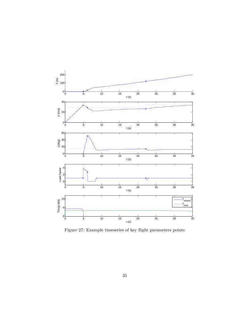
the greatest obstacle clearance. This control strategy is quite complex, requiring a differentcontrol scheme after the obstacle is cleared in order to smoothly transition to a steady climbtrajectory while avoiding rapid accelerations or unsafe flight conditions (in terms of speedand attitude) in case of engine failure. The control system uses a proportional controllerto adjust the angle of attack based on flight speed and climb angle goals, within the liftand drag conditions described by the aircraft polar curves. It’s operation is demonstratedin Figure 27, which shows the timeseries of aircraft altitude, speed, climb angle (γ), loadfactor, and thrust during the takeoff, transition, and initial climb for an example aircraft.The three stars in each plot indicate the points of liftoff, obstacle clearance, and flapretraction. The dashed lines in the speed and climb angle plots represent the optimalclimb conditions for the current flap setting.
The plots show that the control strategies are quite effective. The altitude curve provides areference to the climb trajectory. The speed and climb angle curves show how the aircraftlifts off at a speed greater than its flaps-deployed optimal climb speed and uses that excessspeed to transition to a very high climb angle, before settling down to a more normal climbangle and recovering speed to approach a more sustainable climb condition. The controlsystem can be seen to handle these large speed and climb angle variations effectively, andavoid dangerously-low flight speeds or less-than-ideal climb angles. In fact, as a safetymeasure, the controller ensures that the aircraft is at is optimal climb angle and speedright at the moment it clears the obstacle, as the plots show. At t =22 s the flaps areretracted and the controller can be seen to effectively adjust to the new optimal climbconditions. The load factor plot shows that throughout these transitions, accelerationsstay within reasonable bounds and are for the most part quite smooth. The thrust plotshows both the propeller thrust and the wheel motor thrust during the ground roll. Justbefore liftoff, the drop in the wheel motor thrust indicates that the motors have reachedtheir maximum power output. The small variations in the propeller thrust with flight speeddemonstrate the operation of the performance-curve-based propeller model.
34
0 5 10 15 20 25 30 350
100
200
t (s)
Y (
m)
0 5 10 15 20 25 30 350
20
40
t (s)
V (
m/s
)
0 5 10 15 20 25 30 350
20
40
60
t (s)
γ (d
eg)
0 5 10 15 20 25 30 35
0
2
4
t (s)
Load
Fac
tor
0 5 10 15 20 25 30 350
5
10
t (s)
Thr
ust (
kN)
Twheels
Tprop
Figure 27: Example timeseries of key flight parameters points
35
After clearing the 50 (15.24 m) ft obstacle height, the aircraft continues at full power,intercepting what has been calculated as the maximum climb gradient (as can be seen inFigure 26), until it has cleared 400 ft. This provides the greatest ability to turn aroundand land in the event of an engine failure at these low altitudes. The aircraft then retractsits flaps and accelerates to intercept the maximum climb gradient and speed with no flapsand 90% power - to represent a more sustainable power level for the motor - and thenclimbs to a safe altitude of 1500 ft. The remaining climb to the 4000 ft cruise altitude isdone at the most energy-efficient climb setting.
The aircraft then cruises for 200 miles plus 30 minutes further, at the conditions that havebeen calculated for most efficient cruise. Energy required for descent and landing is notconsidered significant given the high glide ratio of the aircraft, and is assumed to comeout of the 30-minute reserve energy capacity. Landing is only analyzed in terms of thedeceleration required given the stall speed of the aircraft, making sure this falls well withinthe traction limits of the wheels on wet pavement. By this measure, the short landingrequirement was determined to not be an issue.
7.2 Power System Design Optimization
With the scheme created to determine the size of the various power system components,the only decision variables required to specify a design of a given configuration are mainmotor shaft power and wheel motor power. Various other parameters, such as the wingarea and the storage system mass, are contingent on those variables. The optimal designin terms of minimum energy expenditure, specified by these two variables, is found usinga Matlab-based optimizer.
The optimal liftoff speed for obstacle clearance needs to be determined for each design.This is treated as a third decision variable in the optimization. The benefit of delayingliftoff comes from prolonging the contribution of thrust from the wheel motors and thereduced drag from having the flaps retracted during the ground roll. Not surprisinglythen, the optimal liftoff speed varies depending on the amount of thrust contributed bythe wheel motors. It is typically around 20% to 40% greater than stall speed.
Perhaps the next most crucial variable is wing area. Wing area correlates positively withESTOL performance and negatively with cruise speed. Because these constraints act inopposition on wing area, it can be expected that an optimal design will be be on thefrontier of both these constraints. Being on the frontier of the cruise speed constraint (i.e.Vcruise = 45), where cruise speed is a function of weight and wing area (given the wing isoperating at it’s most efficient angle of attack), implies that wing area and aircraft weightare functions of only each other. Equation (1) indicates that this relationship is in factconstant:
36
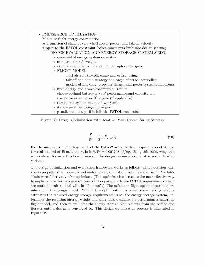
• FMINSEARCH OPTIMIZATIONMinimize flight energy consumptionas a function of shaft power, wheel motor power, and takeoff velocitysubject to the ESTOL constraint (other constraints built into design scheme)
– DESIGN EVALUATION AND ENERGY STORAGE SYSTEM SIZING∗ guess initial energy system capacities∗ calculate aircraft weight∗ calculate required wing area for 100 mph cruise speed∗ FLIGHT MODEL
· model aircraft takeoff, climb and cruise, using:- takeoff and climb strategy and angle of attack controllers- models of lift, drag, propeller thrust, and power system components
∗ from energy and power consumption results,choose optimal battery E-vs-P performance and capacity andsize range extender or IC engine (if applicable)
∗ recalculate system mass and wing area∗ iterate until the design converges∗ penalize the design if it fails the ESTOL constraint
Figure 28: Design Optimization with Iterative Power System Sizing Strategy
S
W=
1
2ρV 2
cruiseC∗L (20)
For the maximum lift to drag point of the GAW-2 airfoil with an aspect ratio of 20 andthe cruise speed of 45 m/s, the ratio is S/W = 0.001298m2/kg. Using this ratio, wing areais calculated for as a function of mass in the design optimization, so it is not a decisionvariable.
The design optimization and evaluation framework works as follows. Three decision vari-ables - propeller shaft power, wheel motor power, and takeoff velocity - are used in Matlab’s“fminsearch” derivative-free optimizer. (This optimizer is selected as the most effective wayto implement performance-based constraints - particularly the ESTOL requirement - whichare more difficult to deal with in “fmincon”.) The noise and flight speed constraints areinherent in the design model. Within this optimization, a power system sizing moduleestimates the required energy storage requirements, sizes the energy storage system, de-termines the resulting aircraft weight and wing area, evaluates its performances using theflight model, and then re-evaluates the energy storage requirements from the results anditerates until a design is converged to. This design optimization process is illustrated inFigure 28.
37
7.3 Design Optimization Results
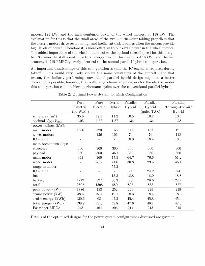
Results from the framework were obtained for the four power system configurations con-sidered: pure electric, serial hybrid, parallel hybrid, and “through-the-air” parallel hybrid.The results are compared in greater detail in Table 2. Except where mentioned otherwise,all of these results sit on the edge of the cruise speed and ESTOL constraints, having acruise speed of 100 mph and clearing a 50 ft height 400 ft from the beginning of the groundroll.
7.3.1 Pure Electric
The most basic power system configuration uses only a single electric motor to power thepropeller and does not use wheel motors to assist with ground roll acceleration. The designoptimization scheme was unable to produce a feasible design with this simple configuration.With the available motor power density and battery energy density, wing lift and dragcoefficients, and the cruise speed and range requirement, a power-to-weight ratio and wingloading combination sufficient to clear the 50 ft obstacle from takeoff was not possible. Thenearest a design of this configuration could come to need clearing the obstacle was within2 m. This is remarkable close, but the tremendous size of the design, with a mass of 2800kg, shows that this configuration is highly impractical for achieving ESTOL performance.
Adding in the use of wheel motors makes a remarkable difference in performance. For thepure electric configuration with a motor driving the propeller and wheel motors drivingthe main landing gear, an aircraft with a mass of 1400 kg was found to satisfy the designrequirements (i.e. having ESTOL capability, 100 mph cruise speed, and 200 mile range).The optimized design is an aircraft with a 320 kW main motor and a combined wheelmotor power rating of 136 kW. The required battery mass is 527 kg. The wing area is17.8 m2. The optimal takeoff speed is 1.35 times the stall speed, to extend the use of thewheel motors. The total energy consumed in a flight (consisting of takeoff, climb, and 200miles plus 30 minutes of cruise) is 72.6 kWh. The equivalent per-passenger fuel economy forthis flight, measured as passenger miles-per-gallon equivalent and based on the equivalencyvalues in [24], is 464 PMPGe.
7.3.2 Series Hybrid
The series hybrid configuration builds on the pure-electric configuration with the additionof a range extender motor-generator and a fuel tank. This takes advantage of the highpower density of gasoline to displace some of the lower power density battery capacity,achieving greater range with less weight, while not affecting the drive system. Because theIC engine needs only be sized to meet the steady cruise power requirements rather than
38
the peak power requirements, and electric motors can be much lighter than IC engines, thisconfiguration can achieve a lighter power system with more peak power than a conventionalIC power system, and more range than an all-electric power system.
First, for illustrative purposes, the battery mass was reduced from 527 kg to 100 kg (enoughcapacity for four full takeoffs) and the reduced weight was taken up by an appropriately-sized range extender system and a fuel tank to maintain the same overall weight. Thischange of only the energy source was calculated to boost the range of the aircraft by about4200 miles (a nearly twenty-fold increase!). This demonstrates the much greater energydensity of gasoline compared to batteries, and also the performance potential of usinghybrid rather than pure electric power systems. The fuel economy of this aircraft, unfor-tunately, was calculated to be 164 PMPGe, less than desired target. However, the powersystem of this aircraft was not optimized. Furthermore, the significant weight reductionas fuel is burnt was not included in the model, so the fuel economy was most certainlyunderpredicted. Regardless, it is important to adhere to the range specifications of theproject to maintain an equal basis for comparison.
A more realistic and comparable exploration of the series hybrid configuration requires thesystem to be optimized and the original range objectives to be adhered to. This was done,with the constraint that the range extender provides the amount of power required forcruise throughout the flight envelope, and the battery only needs to supply the energy inexcess of that power level, during takeoff and climb.
This optimization results in a nearly 40% reduction in the size and weight of the aircraft.The total mass becomes just 880 kg and the wing area becomes 11.2 m2. The main motordownsizes to 155 kW while the wheel motors downsize a lesser amount to 106 kW. Theenergy consumed in the flight is 49.8 kWh. The equivalent fuel economy, now calculatedas a combination of gasoline and electrical energy, is 206 PMPGe, significantly lower thanthe all-electric configuration but still greater than the 200 PMPGe design goal.
7.3.3 Parallel Hybrid
The parallel hybrid configuration achieves similar benefits as the series hybrid configura-tion, but rather than using the IC engine to generate electricity to power the drive motor,it uses an IC engine to drive the propeller in parallel with the electric motor, avoidingthe efficiency losses of electrical-mechanical conversions. This arrangement is particularlysuited to constant-speed propeller aircraft, where the near-constant propeller speed meansthat the IC engine can always operate near its peak efficiency.
A parallel power system can be arranged so that either the torques add, or the speedsadd (by using a differential). For a constant-pitch propeller as used here, the torqueaddition approach is more appropriate because at lower flight speeds where greater power
39
is needed (during takeoff and climb), it is torque rather than speed that is the limitingfactor on propulsive power. This approach is also simpler and lighter, allowing the ICengine and motor to share the same shaft and avoiding a differential. The electric motorcan also be used as a generator, enabling battery recharging without a separate component.Disconnecting the motor during cruise by means of a clutch may be desirable for bestefficiency. The design optimization was done with the IC engine sized to provide all of thepower during cruise. In one design, the IC engine is used throughout the flight. In the otherdesign, the IC engine is not used during the takeoff and climb to maintain quiet operationduring those times. The results for both these designs are very similar, indicating that forthese sorts of power system configurations it is very feasible to avoid using the IC engineduring takeoff without any performance penalty.
The optimization results in a slightly lighter aircraft than the series hybrid configuration.For the quiet takeoff design, the main electric motor rating is 153 kW, the combined wheelmotor rating is 76 kW, and the IC engine shaft power rating is 18.4 kW. The batterymass is 28.6 kg and 18.9 kg of fuel is required for the flight. The total aircraft mass is838 kg and the wing area is 10.7 m2. The total energy consumed in a flight is 48.1 kWhand the fuel economy is 213 PMPGe, both a marginal improvement over the series hybridconfiguration.
7.3.4 “Through-the-Air” Parallel hybrid
The ”through-the-air” parallel hybrid configuration is analogous to the ”through-the-road”parallel hybrid configuration used in ground vehicles, in which an electric motor drives oneset of wheels and an IC engine drives another set of wheels, avoiding mechanical couplingbetween the two power systems. Avoiding the mechanical coupling is advantageous forweight-sensitive aircraft. The configuration is also advantageous if folding propellers areused for the electric motor-driven propellers. This way, the IC engine and propeller can beoptimized to provide all required cruise thrust, while additional propeller area is availableduring takeoff and climb, where maximum propulsive power output is critical but aero-dynamic efficiency is less crucial. (The additional propeller area provides a more efficientpower-to-thrust conversion, but may be less efficient than a single propeller during cruiseoperation.) For the configuration, two electric motor-driven folding propellers are situatedon the fronts of the pylons and the main pusher propeller is driven solely by an IC engine.The pylons work very well for this purpose because folding propellers are most aerodynamicwhen folded if on the front rather than mounted as pushers.
The optimized design for this configuration is very similar in performance to the otherparallel hybrid design, with 827 kg total mass, a 10.5 m2 wing area, and a total flightenergy consumption of 47.6 kWh. The IC engine is again sized to provide cruise power, at18.3 kW. The difference in this configuration is the lower combined power of the electric
40
motors, 121 kW, and the high combined power of the wheel motors, at 118 kW. Theexplanation for this is that the small areas of the two 2-m-diameter folding propellers thatthe electric motors drive result in high and inefficient disk loadings when the motors providehigh levels of power. Therefore it is more effective to put extra power in the wheel motors.The added importance of the wheel motors raises the optimal takeoff speed for this designto 1.38 times the stall speed. The total energy used in this design is 47.6 kWh and the fueleconomy is 215 PMPGe, nearly identical to the normal parallel hybrid configuration.
An important disadvantage of this configuration is that the IC engine is required duringtakeoff. This would very likely violate the noise constraints of the aircraft. For thatreason, the similarly performing conventional parallel hybrid design might be a betterchoice. It is possible, however, that with larger-diameter propellers for the electric motorthis configuration could achieve performance gains over the conventional parallel hybrid.
Table 2: Optimal Power System for Each Configuration
Pure Pure Serial Parallel Parallel ParallelElectric Electric Hybrid Hybrid Hybrid “through-the air”
peak power (kW) 1886 453 252 226 229 219cruise power (kW) 48.5 27.4 19.1 18.3 18.4 18.3cruise energy (kWh) 120.6 68 47.3 45.4 45.8 45.4
total energy (kWh) 138.7 72.6 49.8 47.6 48.1 47.6Passenger-MPGe 243 464 206 214 213 215
Details of the optimized designs for the power system configurations discussed are given in
41
Table 2. The table shows the distribution of mass in the aircraft between energy storageand power conversion equipment, as well as the overall energy expenditure and peak powerlevels during the flight. The similar performance of all of the hybrid configurations isapparent. Clearly there is a trade off between the lower emissions of an all-electric designand the greater performance of a hybrid design. In addition to proving the feasibility ofthe wheel motor concept, this trade off is one of the main findings of this project. However,the trade off is extremely dependent on where the aircraft’s electricity comes from - GFCvalues were used in this report but for a more serious analysis, more attention would needto be paid to these equivalency values. Lastly, in addition to more accurate representationof this trade off, cost factors would need to be considered in order to be able to decidewhich power configuration is best.
8 Conclusion
Electric-powered aircraft are becoming increasingly feasible, both technically and econom-ically, as electric power system technologies improve, reducing greenhouse gas emissionsbecomes a more widely-accepted priority, and increasing levels of travel congestion promptinterest in alternative transportation paradigms such as “pocket airport” networks. Thequietness and high power densities of electric motors make electric-powered aircraft es-pecially promising for urban applications where noise and takeoff distance are impossibleconstraints for conventionally powered aircraft.
The many high-efficiency and/or high-lift technologies applicable with electric-poweredaircraft, as discussed in Section 4.5, can lead to creative aircraft concepts that have thepossibility of achieving new levels of performance. Some examples were given in Section 6.1.Out of these concepts, the configuration using wheel motors to boost takeoff performancewas chosen for further exploration.
After establishing reasonable performance specifications for the airframe, propellers, mo-tors, engines, and batteries, a design optimization framework was constructed. This frame-work combines an optimizer for power system component sizes, a two-dimensional numeri-cal flight performance model with associated flightpath controllers, and a number of built-indesign tools to find and evaluate the optimal specifications for a given power system con-figuration. Using this tool over a range of configurations - from a pure-electric powersystem to one combining electric motors and an IC engine in a parallel hybrid arrange-ment - provided data from which a number of conclusions can be made relating to a wheelmotor-assisted, ESTOL, electric aircraft.
• The use of wheel motors greatly improves the ESTOL performance of electric aircraft,to the extent that the aircraft considered here cannot otherwise meet the GFC IIESTOL requirement.
42
• Takeoff speeds of 30% to 40% above stall speed become optimal for ESTOL perfor-mance when wheel motors and fast-actuating flaps are used.
• Using a pure-electric power system with wheel motors, the requirements of the GFCII can be met, and a very high equivalent fuel economy of more than double the 200PMPGe requirement can be realized.
• Using a hybrid power system configuration can greatly extend the aircraft rangewithout affecting ESTOL performance.
• A hybrid power system can also significantly reduce the size and weight of the aircraft,however the equivalent fuel economy, using the equivalency data of the GFC, issignificantly reduced.
• Performance differences between serial hybrid, parallel hybrid, and parallel “through-the-air” hybrid configurations are minimal for the aircraft concept examined here.The choice of hybrid configuration may therefore be more a question of cost, noise,and reliability rather than of flight performance.
There are a number of steps that could be taken to further support this design explorationwork, before continuing into more detailed design. The arbitrary parasite drag coefficientselected to result in a 25:1 glide ratio could be checked against the reality of the airframeby using empirically-determined drag coefficients for the fuselage and wing pylons andalso accounting for the drag of the vertical and horizontal stabilizers. The feasibility ofthe 300 kg base structural weight could be checked by performing some simple structuralsizing given the loads on the aircraft. And, very importantly, a cost estimate of the designshould be made to determine whether they concept is at all feasible in an economic sense.Comparing the costs of the different hybrid configurations would be a valuable addition tothis work.
43
References
[1] D. P. Wells, “NASA green flight challenge: Conceptual design approaches andtechnologies to enable 200 passenger miles per gallon,” 2011. [Online]. Available:http://www.nasa.gov/pdf/584453main Green Flight Challenge TAGGED.pdf
[2] B. A. Seeley, “Faster and greener - pocket airports,” CAFE Foundation, Nov. 2010.[Online]. Available: http://cafefoundation.org/public/2010 08 16/P8.Essay.Final -sm.pdf
[3] “Antares 20E,” Lange Aviation. [Online]. Available: http://www.lange-aviation.com/htm/english/products/antares 20e/antares 20E.html
[4] “Yuneec e430,” Yuneec Inc. [Online]. Available:http://yuneeccouk.site.securepod.com/Aircraft specification.html
[5] “Taurus g4 flies at the NASA GFC!” [Online]. Available:http://www.pipistrel.si/news/taurus-g4-is-flying-at-the-nasa-gfc/
[10] W. A. Mair and D. L. Birdsall, Aircraft Performance, ser. Cambridge Aerospace Series.Cambridge, UK: Press Syndicate of the University of Cambridge, 1992, no. 5.
[12] D. P. Raymer, Aircraft Design: A Conceptual Approach, 4th ed. Reston, Virginia:American Institute of Aeronautics and Astronautics, 2006.
[13] “Future of gliding - front electric sustainer.” [Online]. Available: http://www.front-electric-sustainer.com/technology.php
[14] W. H. Mason, “Configuration aerodynamics - part 2 - powered lift systems.” [Online].Available: http://www.dept.aoe.vt.edu/ mason/Mason f/HiLiftPresPt2.pdf
[15] A. F. Burke, “Batteries and ultracapacitors for electric, hybrid, and fuel cellvehicles,” in Proceedings of the IEEE, vol. 95. IEEE, Apr. 2007. [Online].
44
Available: http://lifepo4.info/Battery study/Batteries/Batteries and Ultracapaci-tors for Electric Hybrid and Fuel Cell Vehicles.pdf
[17] W. H. Wentz, “Wind tunnel tests of the GA (W)-2 airfoil with20/25/State University, Tech. Rep., Jan. 1977. [Online]. Available:http://www.reaa.ru/yabbfilesB/Attachments/19790001850 1979001850.pdf
[18] B. W. McCormick, Aerodynamics, Aeronautics, and Flight Mechanics, second edi-tion ed. Danvers: John Wiley and Sons, 1995.
[19] Power drive system specifications. Yuneec Inc. [Online]. Available:http://yuneeccouk.site.securepod.com/PowerMotor Tech spec.html