Mechanical Actuators Mechanical systems Although now electronic systems are being used for many functions that previously were fulfilled by mechanism; mechanisms are still being used to provide the following functions: 1. Force amplification e.g. levers 2. Change of speed e.g. gears 3. Transfer of rotation about one axis to rotation about another axis e.g. belt 4. Particular types of motion e.g. that given by a quick return mechanism This section introduce kinematics analysis of the mechanism i.e. consideration of motion without regard to forces
Transcript
Mechanical ActuatorsMechanical systems
Although now electronic systems are being used for many functions that previously were fulfilled by mechanism; mechanisms are still being used to provide the following functions:
1. Force amplification e.g. levers
2. Change of speed e.g. gears
3. Transfer of rotation about one axis to rotation a bout another axis e.g. belt
4. Particular types of motion e.g. that given by a q uick return mechanism
This section introduce kinematics analysis of the me chanism i.e.consideration of motion without regard to forces
Figure 8.1 Types of motion: (a) translational, (b) rotational
Types of Motion: Freedom & ConstraintsThe motion of any rigid body can be considered to be a combination of translation and rotational motions
Translation motion is a movement which can be resolved into components along one or more of the three axis x,y or zA rotational motion is one which has components rotating about one or more of the axis
Types of Motion:
• A complex motion is the combination of the translation and rotation motions
• Example of complex motion :• Instruct a robot to pickup a pencil
from a table: you should breakup motion into small simple motion, e.g. instruct joint 1 to rotate by 20 degree then link 2 to be extended by 4 mm….etc
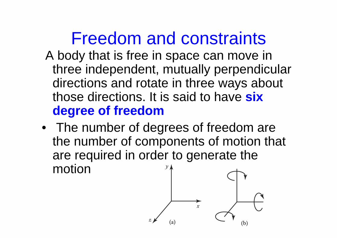
Freedom and constraintsA body that is free in space can move in
three independent, mutually perpendicular directions and rotate in three ways about those directions. It is said to have six degree of freedom
• The number of degrees of freedom are the number of components of motion that are required in order to generate the motion
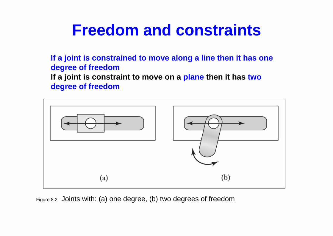
Figure 8.2 Joints with: (a) one degree, (b) two degrees of freedom
If a joint is constrained to move along a line then it has one degree of freedomIf a joint is constraint to move on a plane then it has two degree of freedom
Freedom and constraints
• The problem in a design is to reduce the number of degrees of freedom which requires an appropriate number and orientation of constraint
• Fixed body implies zero degree of freedom implies 6 constraints
• Concept in design: In fixing a body or guiding it to a particular type of motion, the minimum number of constraints should be used “kinematics design”
Freedom and constraints
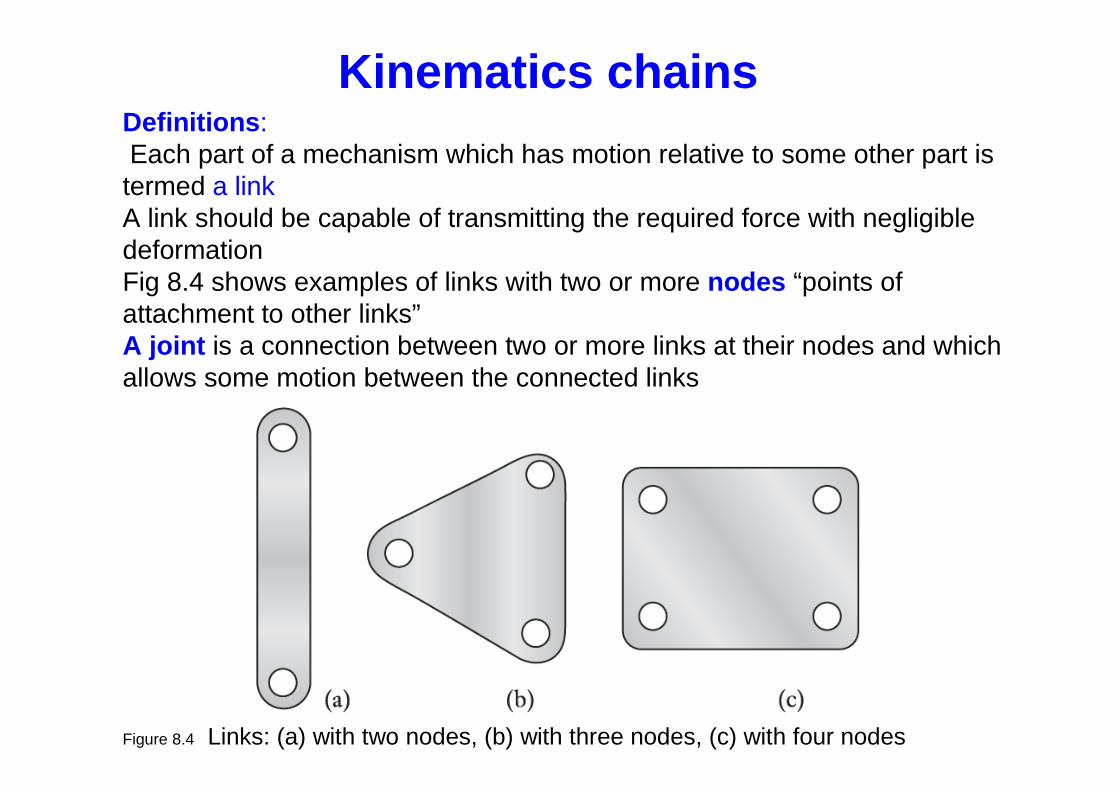
Figure 8.4 Links: (a) with two nodes, (b) with three nodes, (c) with four nodes
Definitions :Each part of a mechanism which has motion relative to some other part is termed a linkA link should be capable of transmitting the required force with negligible deformationFig 8.4 shows examples of links with two or more nodes “points of attachment to other links”A joint is a connection between two or more links at their nodes and which allows some motion between the connected links
Kinematics chains
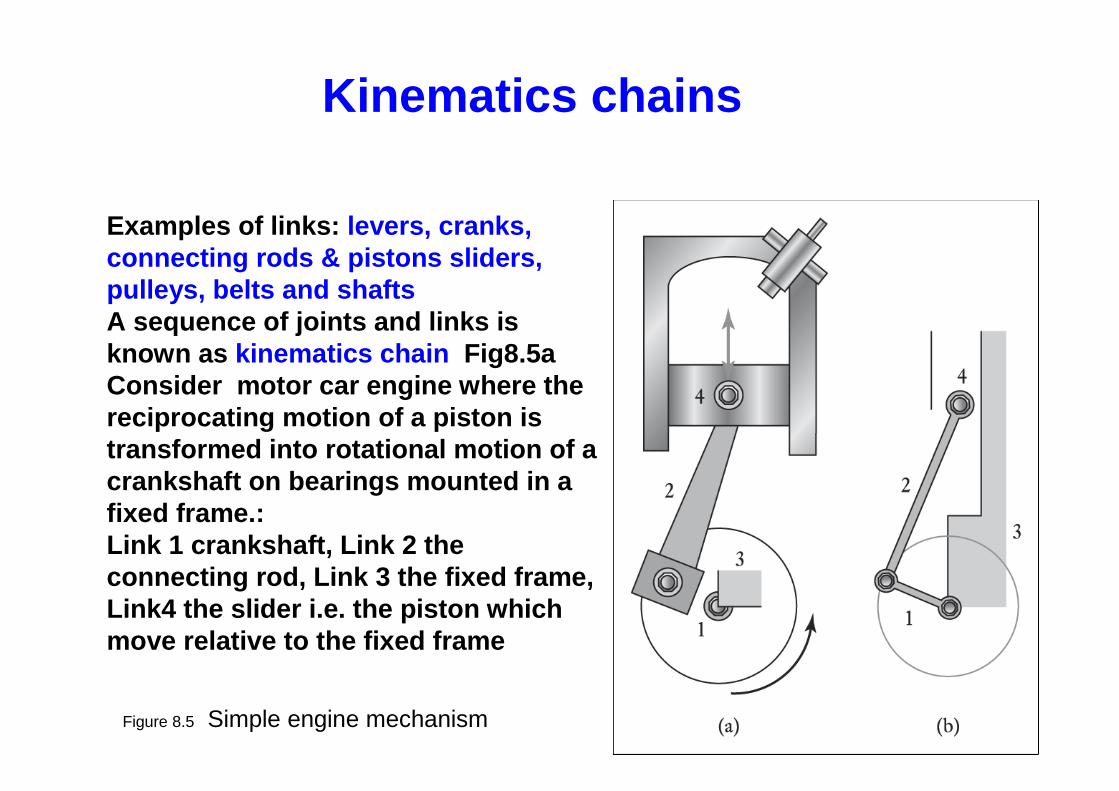
Figure 8.5 Simple engine mechanism
Examples of links: levers, cranks, connecting rods & pistons sliders, pulleys, belts and shaftsA sequence of joints and links is known as kinematics chain Fig8.5aConsider motor car engine where the reciprocating motion of a piston is transformed into rotational motion of a crankshaft on bearings mounted in a fixed frame.: Link 1 crankshaft, Link 2 the connecting rod, Link 3 the fixed frame, Link4 the slider i.e. the piston which move relative to the fixed frame
Kinematics chains
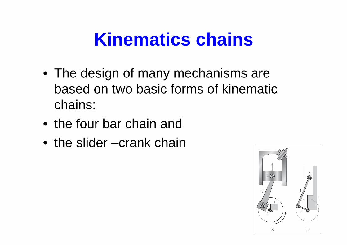
• The design of many mechanisms are based on two basic forms of kinematic chains:
• the four bar chain and • the slider –crank chain
Kinematics chains
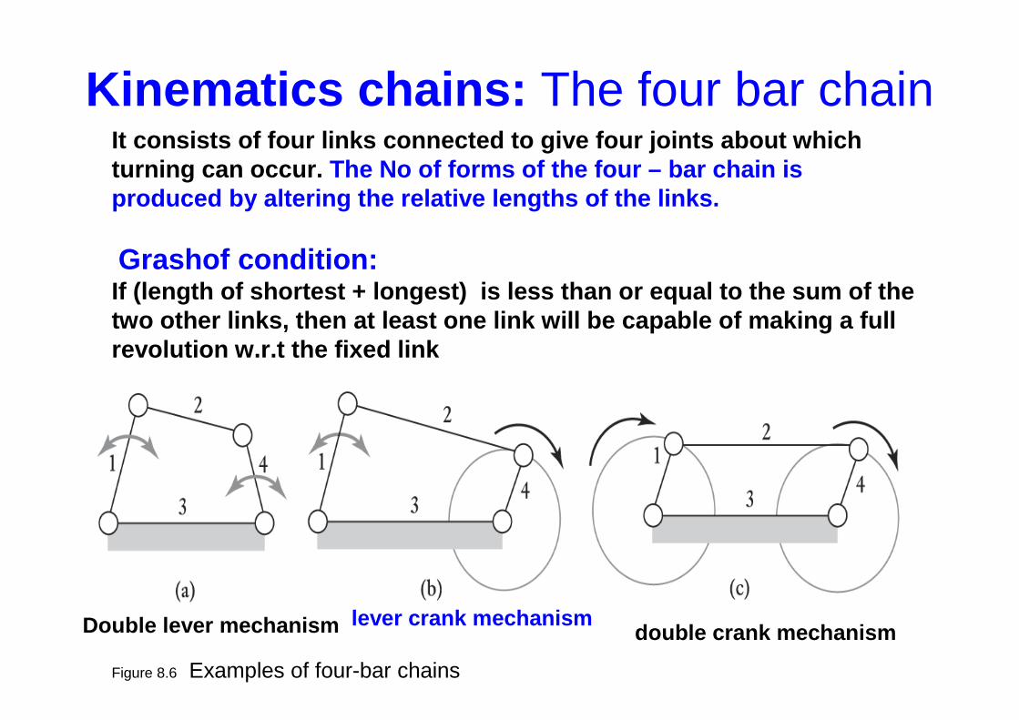
Figure 8.6 Examples of four-bar chains
It consists of four links connected to give four join ts about which turning can occur. The No of forms of the four – bar chain is produced by altering the relative lengths of the links .
Grashof condition:If (length of shortest + longest) is less than or equa l to the sum of the two other links, then at least one link will be capa ble of making a full revolution w.r.t the fixed link
Kinematics chains: The four bar chain
Double lever mechanism lever crank mechanismdouble crank mechanism
Kinematics chains:Slider–crank mechanism
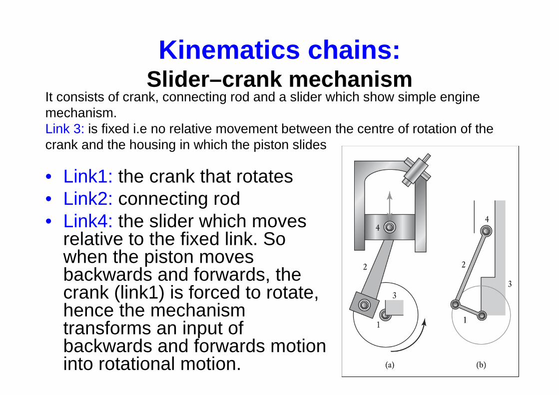
• Link1: the crank that rotates• Link2: connecting rod• Link4: the slider which moves
relative to the fixed link. So when the piston moves backwards and forwards, the crank (link1) is forced to rotate, hence the mechanism transforms an input of backwards and forwards motion into rotational motion.
It consists of crank, connecting rod and a slider which show simple engine mechanism. Link 3: is fixed i.e no relative movement between the centre of rotation of the crank and the housing in which the piston slides
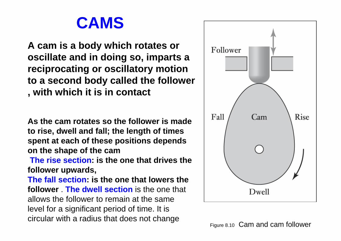
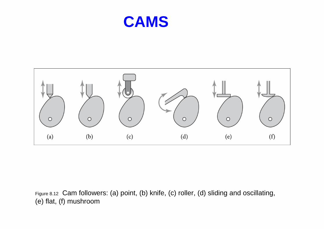
Figure 8.10 Cam and cam follower
A cam is a body which rotates or oscillate and in doing so, imparts a reciprocating or oscillatory motion to a second body called the follower , with which it is in contact
CAMS
As the cam rotates so the follower is made to rise, dwell and fall; the length of times spent at each of these positions depends on the shape of the camThe rise section : is the one that drives the follower upwards, The fall section : is the one that lowers the follower . The dwell section is the one that allows the follower to remain at the same level for a significant period of time. It is circular with a radius that does not change
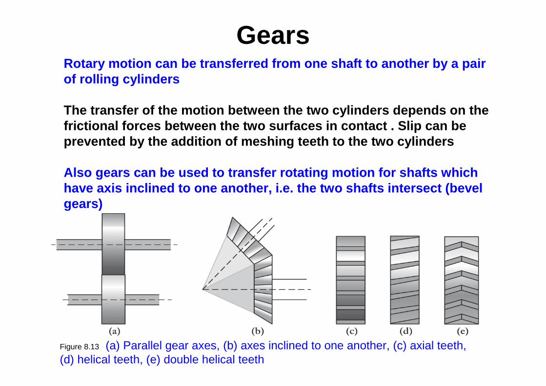
Rotary motion can be transferred from one shaft to a nother by a pair of rolling cylinders
The transfer of the motion between the two cylinders d epends on the frictional forces between the two surfaces in contact . Slip can be prevented by the addition of meshing teeth to the tw o cylinders
Also gears can be used to transfer rotating motion for shafts which have axis inclined to one another, i.e. the two shaf ts intersect (bevel gears)
Gears
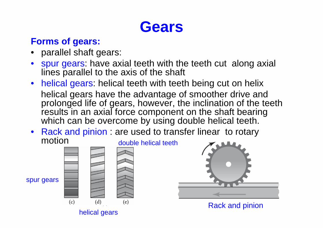
Forms of gears:• parallel shaft gears:• spur gears: have axial teeth with the teeth cut along axial
lines parallel to the axis of the shaft• helical gears: helical teeth with teeth being cut on helix
helical gears have the advantage of smoother drive and prolonged life of gears, however, the inclination of the teeth results in an axial force component on the shaft bearing which can be overcome by using double helical teeth.
• Rack and pinion : are used to transfer linear to rotary motion
Gears
Rack and pinion
spur gears
helical gears
double helical teeth
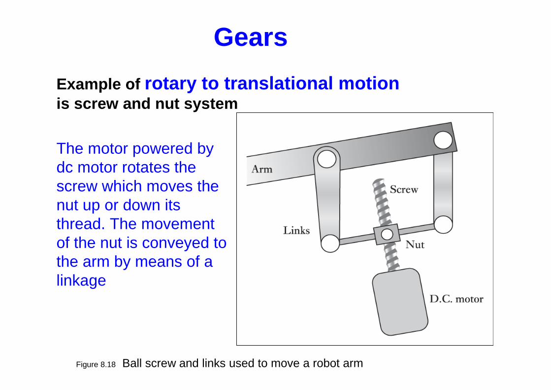
Figure 8.18 Ball screw and links used to move a robot arm
The motor powered by dc motor rotates the screw which moves the nut up or down its thread. The movement of the nut is conveyed to the arm by means of a linkage
Example of rotary to translational motionis screw and nut system
Gears
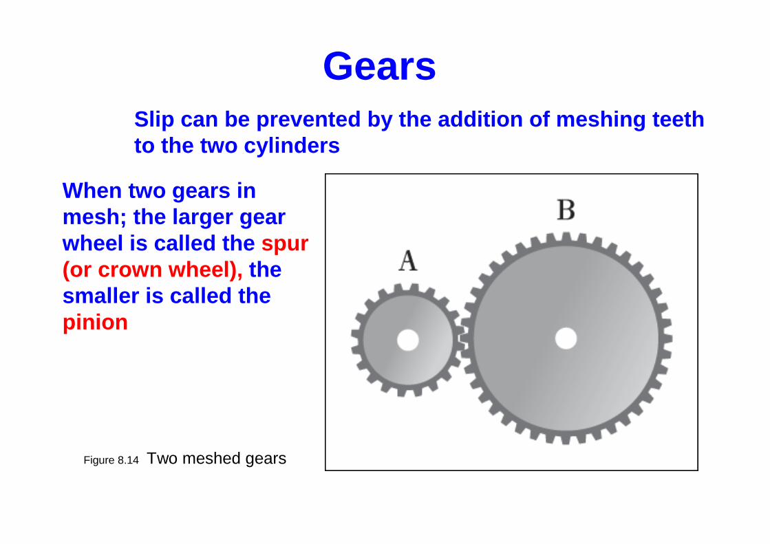
Figure 8.14 Two meshed gears
When two gears in mesh; the larger gear wheel is called the spur (or crown wheel), the smaller is called the pinion
Slip can be prevented by the addition of meshing te eth to the two cylinders
Gears
Figure 8.14 Two meshed gears
Gears: ratio
BA
B
A
AonteethofNo
BonteethofNo
ωωωω
2
240
80
=
===
2=== ratiogeard
d
A
B
B
A
ωω
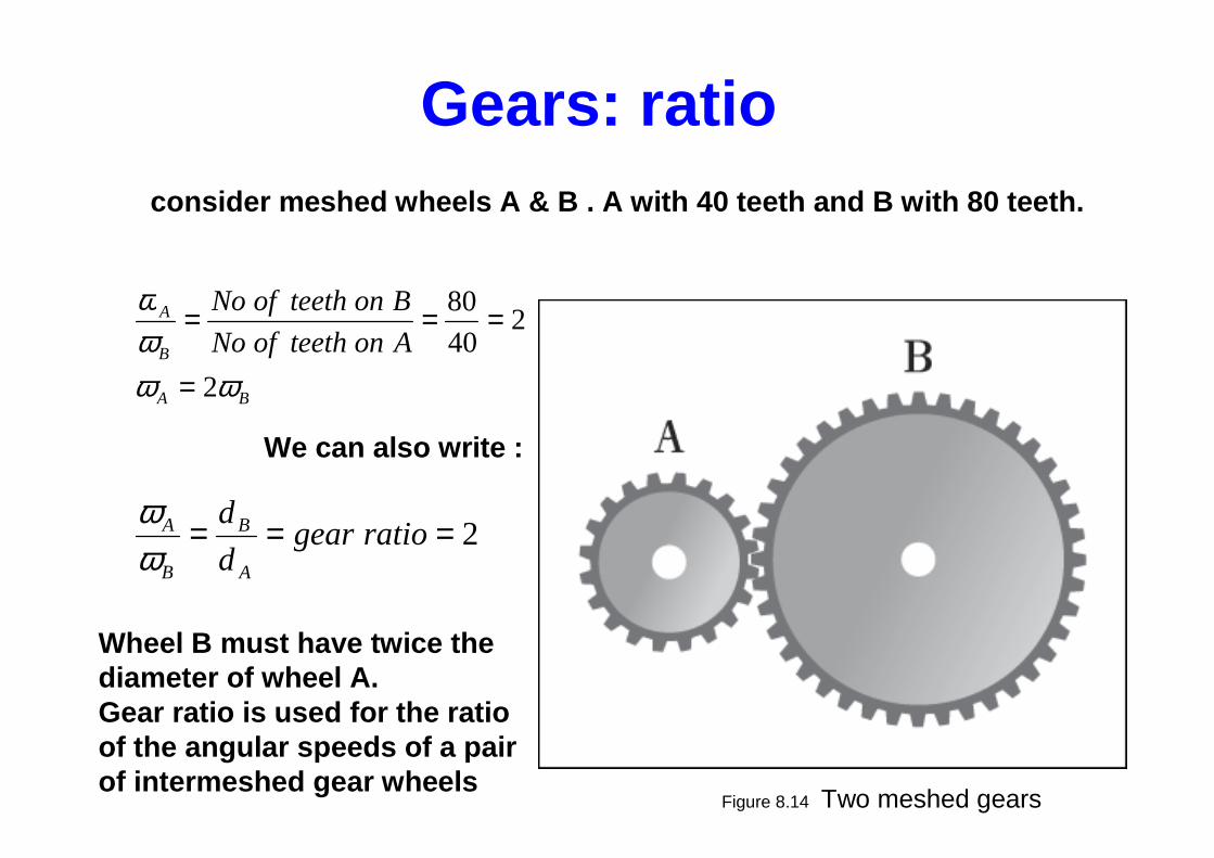
consider meshed wheels A & B . A with 40 teeth and B with 80 teeth.
We can also write :
Wheel B must have twice the diameter of wheel A.Gear ratio is used for the ratio of the angular speeds of a pair of intermeshed gear wheels
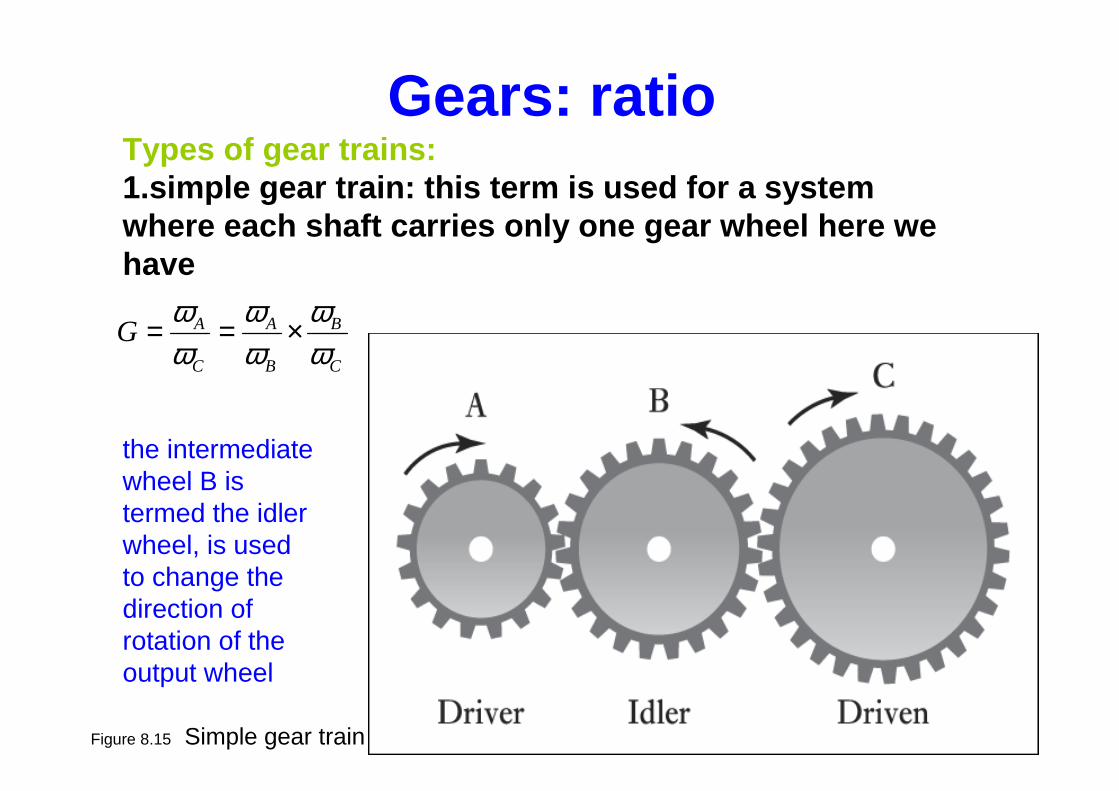
Figure 8.15 Simple gear train
Types of gear trains:1.simple gear train: this term is used for a system where each shaft carries only one gear wheel here w e have
C
B
B
A
C
AGωω
ωω
ωω
×==
the intermediate wheel B is termed the idler wheel, is used to change the direction of rotation of the output wheel
Gears: ratio
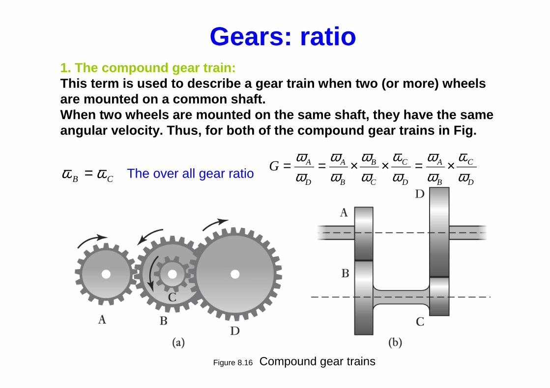
Figure 8.16 Compound gear trains
CB ωω =D
C
B
A
D
C
C
B
B
A
D
AGωω
ωω
ωω
ωω
ωω
ωω
×=××==
1. The compound gear train:This term is used to describe a gear train when two ( or more) wheels are mounted on a common shaft.When two wheels are mounted on the same shaft, they have the same angular velocity. Thus, for both of the compound gear trains in Fig.
The over all gear ratio
Gears: ratio
CDBA rrrr +=+
D
AGωω
==×= 418
36
15
30
rpmAD 404/160
4===
ωω
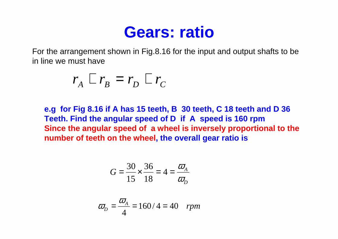
For the arrangement shown in Fig.8.16 for the input and output shafts to be in line we must have
e.g for Fig 8.16 if A has 15 teeth, B 30 teeth, C 18 teeth and D 36 Teeth. Find the angular speed of D if A speed is 160 rpmSince the angular speed of a wheel is inversely propo rtional to the number of teeth on the wheel , the overall gear ratio is
Gears: ratio
Figure 8.19 Ratchet and pawl
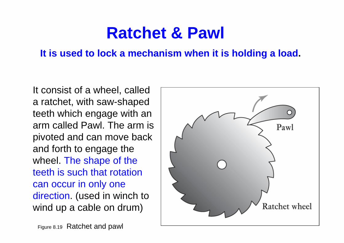
It consist of a wheel, called a ratchet, with saw-shaped teeth which engage with an arm called Pawl. The arm is pivoted and can move back and forth to engage the wheel. The shape of the teeth is such that rotation can occur in only one direction. (used in winch to wind up a cable on drum)
Ratchet & PawlIt is used to lock a mechanism when it is holding a load .
BB
AA r
v
r
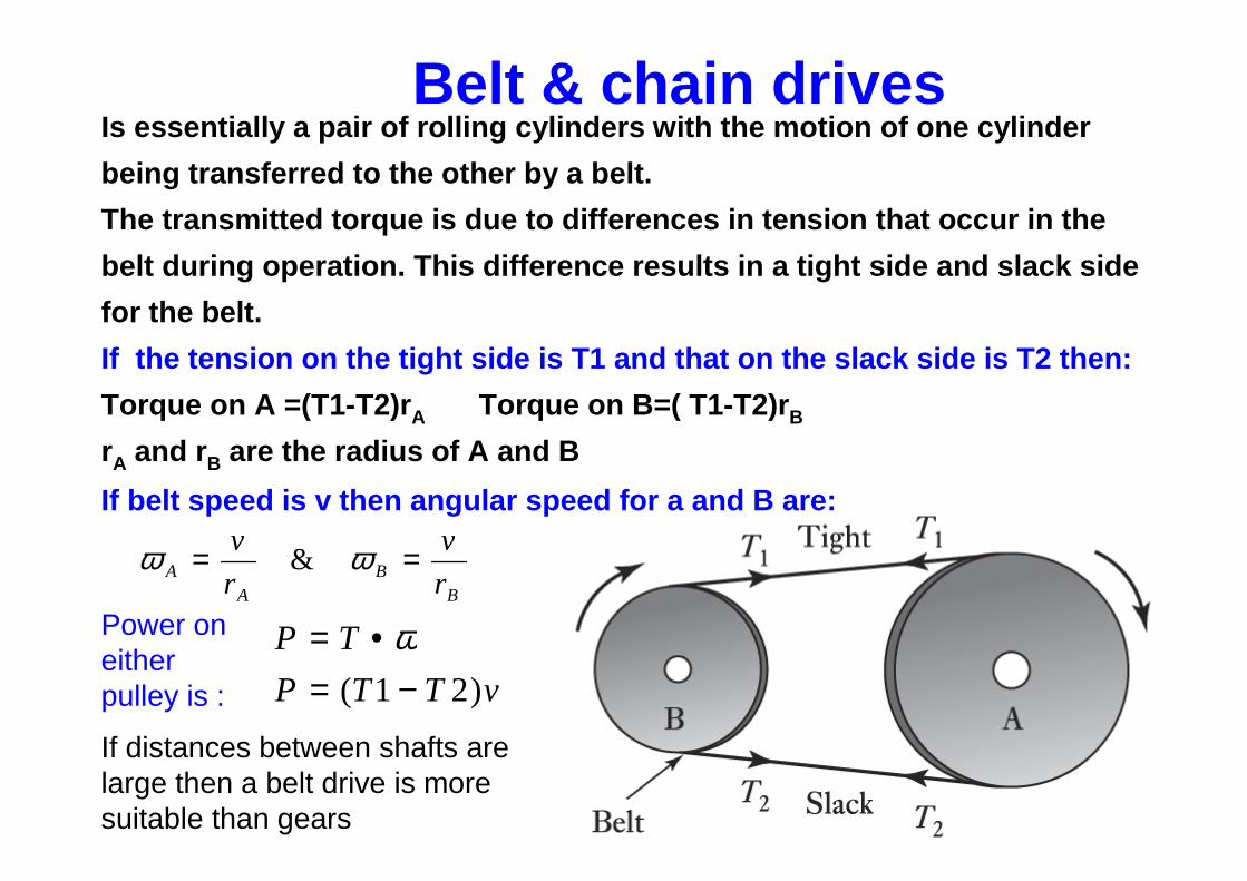
v == ωω &
vTTP
TP
)21( −=•= ω
Is essentially a pair of rolling cylinders with the mo tion of one cylinder
being transferred to the other by a belt.
The transmitted torque is due to differences in tensi on that occur in the
belt during operation. This difference results in a tig ht side and slack side
for the belt.
If the tension on the tight side is T1 and that on the slack side is T2 then:
Torque on A =(T1-T2)r A Torque on B=( T1-T2)r B
rA and r B are the radius of A and B
Power on either pulley is :
If distances between shafts are large then a belt drive is more suitable than gears
Belt & chain drives
If belt speed is v then angular speed for a and B are :
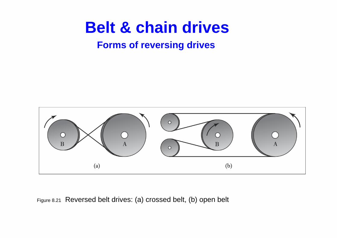
Figure 8.21 Reversed belt drives: (a) crossed belt, (b) open belt
Forms of reversing drives
Belt & chain drives
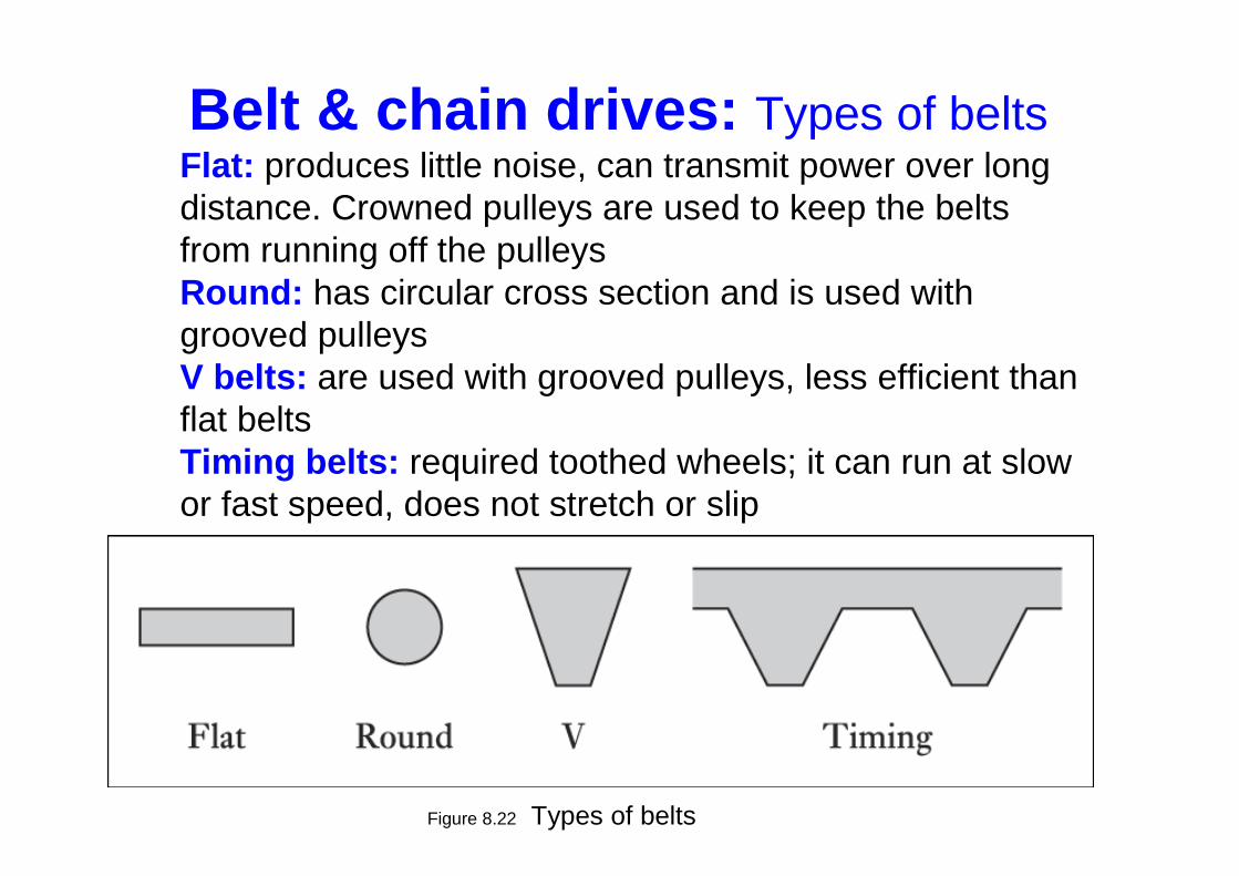
Figure 8.22 Types of belts
Flat: produces little noise, can transmit power over long distance. Crowned pulleys are used to keep the belts from running off the pulleysRound: has circular cross section and is used with grooved pulleysV belts: are used with grooved pulleys, less efficient than flat beltsTiming belts: required toothed wheels; it can run at slow or fast speed, does not stretch or slip
Belt & chain drives: Types of belts
Chains
• Slip can be prevented by the use of chains which lock into teeth on the rotating cylinders.
• The drive mechanism used with bicycle is an example of a chain drive.
• It enables a number of shafts to be driven by single wheel and so give a multiple drive
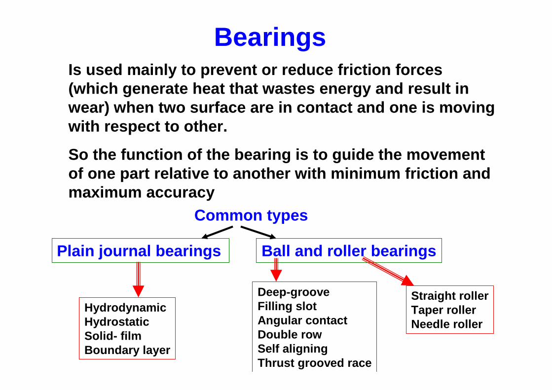
BearingsIs used mainly to prevent or reduce friction forces (which generate heat that wastes energy and result in wear) when two surface are in contact and one is mo ving with respect to other.
So the function of the bearing is to guide the move ment of one part relative to another with minimum fricti on and maximum accuracy
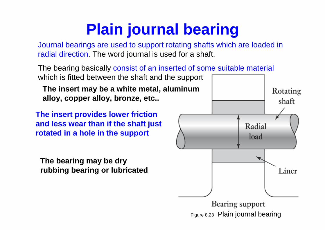
Journal bearings are used to support rotating shafts which are loaded in radial direction. The word journal is used for a shaft.
The bearing basically consist of an inserted of some suitable materialwhich is fitted between the shaft and the support
The insert may be a white metal, aluminum alloy, copper alloy, bronze, etc..
The insert provides lower friction and less wear than if the shaft just rotated in a hole in the support
The bearing may be dry rubbing bearing or lubricated
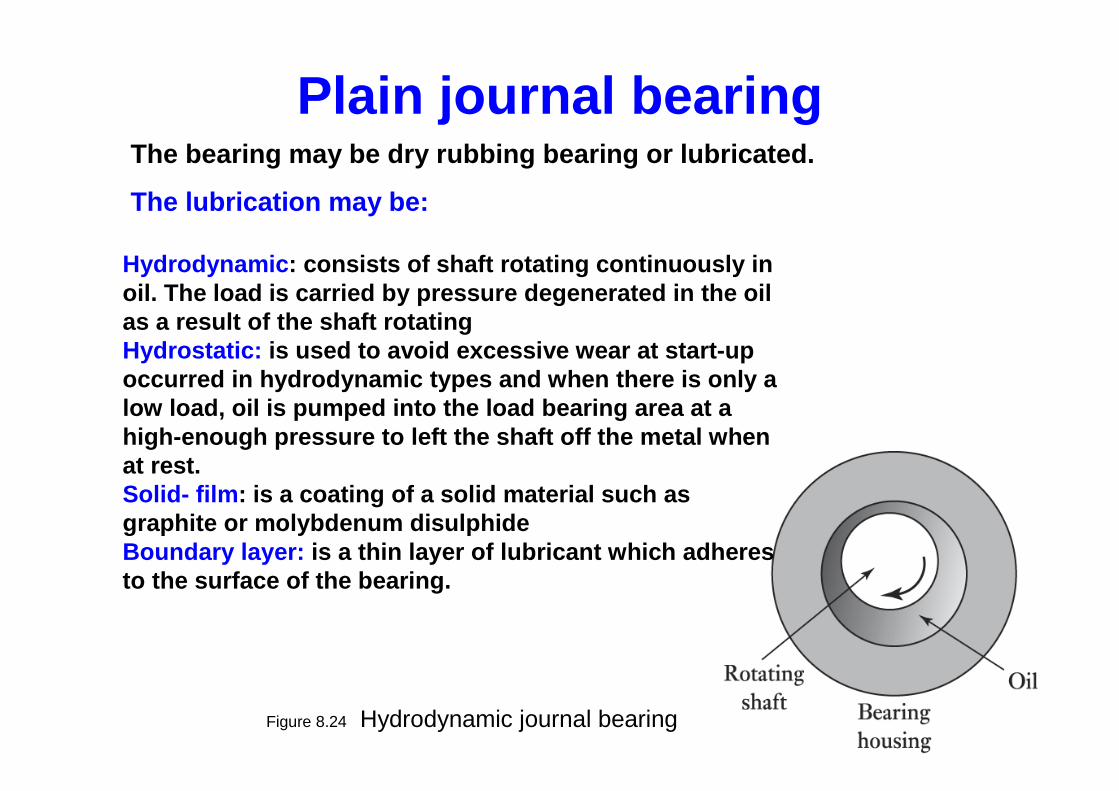
Figure 8.24 Hydrodynamic journal bearing
The bearing may be dry rubbing bearing or lubricated.
The lubrication may be:
Plain journal bearing
Hydrodynamic : consists of shaft rotating continuously in oil. The load is carried by pressure degenerated in the oil as a result of the shaft rotatingHydrostatic: is used to avoid excessive wear at start-up occurred in hydrodynamic types and when there is on ly a low load, oil is pumped into the load bearing area at a high-enough pressure to left the shaft off the meta l when at rest. Solid- film : is a coating of a solid material such as graphite or molybdenum disulphideBoundary layer: is a thin layer of lubricant which adheres to the surface of the bearing.
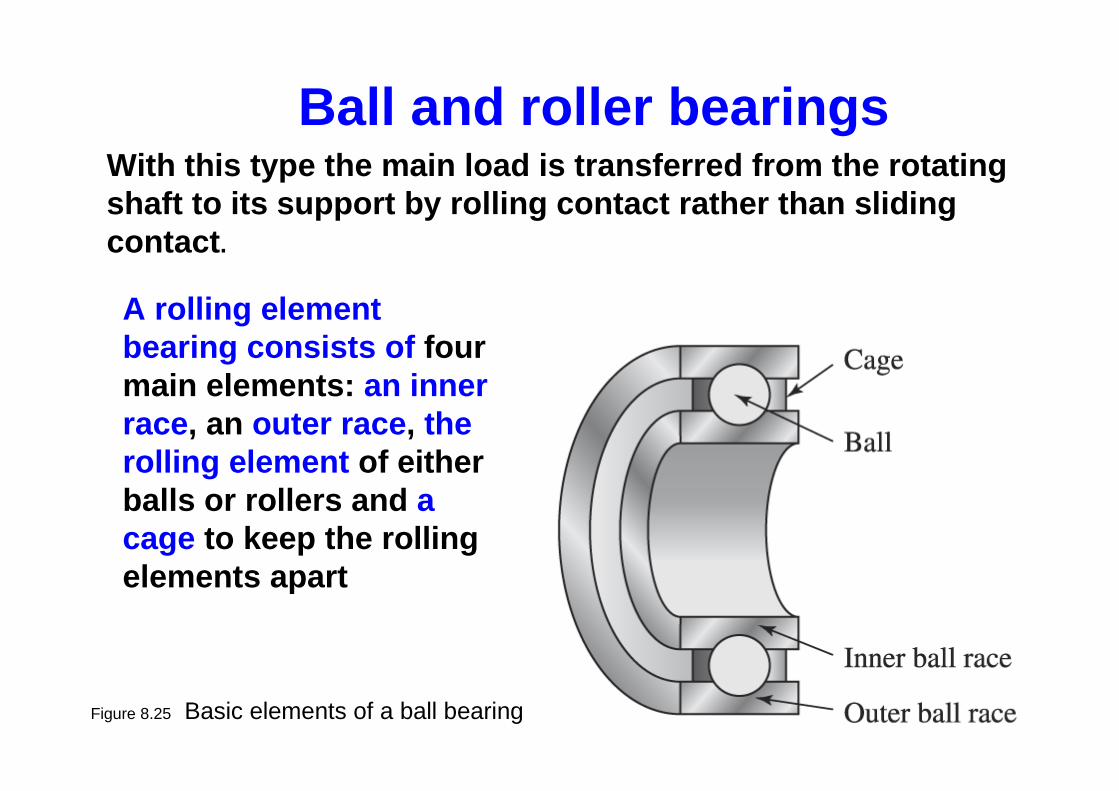
Figure 8.25 Basic elements of a ball bearing
Ball and roller bearingsWith this type the main load is transferred from th e rotating shaft to its support by rolling contact rather than sliding contact .
A rolling element bearing consists of four main elements: an inner race, an outer race , the rolling element of either balls or rollers and a cage to keep the rolling elements apart
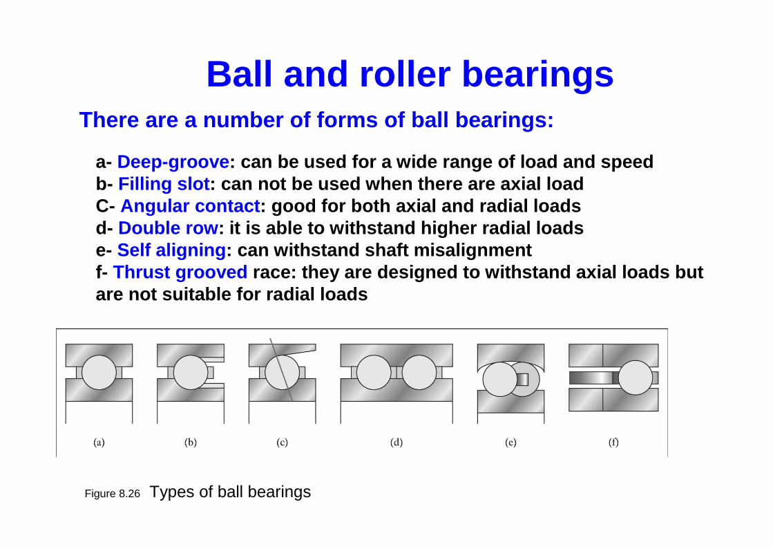
Figure 8.26 Types of ball bearings
Ball and roller bearingsThere are a number of forms of ball bearings:
a- Deep-groove : can be used for a wide range of load and speed b- Filling slot : can not be used when there are axial loadC- Angular contact : good for both axial and radial loads d- Double row : it is able to withstand higher radial loadse- Self aligning : can withstand shaft misalignment f- Thrust grooved race: they are designed to withstand axial loads but are not suitable for radial loads
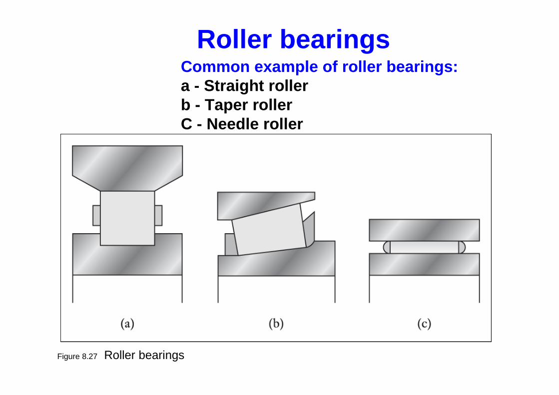
Figure 8.27 Roller bearings
Common example of roller bearings:a - Straight rollerb - Taper rollerC - Needle roller