50
LICENTIATE THESIS Mechanical Characterization of Heterogeneous Brittle Materials Laura Suarez Collazos Solid Mechanics

LICENTIATE T H E S I S
Laura Suarez Collazos M
echanical Characterization of H
eterogeneous Brittle M
aterials
Mechanical Characterization of Heterogeneous Brittle Materials
Laura Suarez Collazos
Solid Mechanics

Mechanical Characterization ofHeterogeneous Brittle Materials
Laura Suarez Collazos
Division of Solid MechanicsDepartment of Engineering Sciences and Mathematics
Lulea University of TechnologyLulea, Sweden
Licentiate Thesis in Solid Mechanics

ii

Preface
This thesis was carried out at the Division of Solid Mechanics, Department of EngineeringSciences and Mathematics at Lulea University of Technology, Sweden. This work wassupported by EIT Raw Materials ”GREENY”, Grinding Energy Efficiency, upscalingproject grant number 18009.
I would like to express my gratitude to my main supervisor, Prof. Par Jonsen andco-supervisors Assoc. Prof Jorgen Kajberg and Dr. Simon Larsson, for their supportand guidance throughout my arrival to Sweden, PhD studies at the division and workwithin the European project. I would also like to thank Ulf Stenman and Lars Friskfor their help with the manufacturing and preparation of the samples and particularly,Jan Granstrom for his patience and contribution to the experimental work. I would liketo extend my sincere thanks to my colleagues at the division and close friends for theirunhesitating support and belief in me. Last but not least, I would like to express mygratitude to my parents, my brother and my Swedish family that, without their support,this work would not have been possible.
iii

iv

Abstract
Comminution is one of the highest energy-consuming processes in the mining and mineralprocessing industry by consuming around 4% of the global generated energy with anoverall efficiency of 1-3%. Different approaches to the optimization of processes havebeen developed, but there is still room for improvement. The macro events where energyis mostly spent require numerical methods, so an overall optimization of the system isperformed by the analysis and optimization of individual subsystems, such as machinesand material to be crushed. One of the challenges when applying numerical analysis lieson the calibration of the models with mechanical parameters inherent to the constitutivelaws and physics of the system.
It has been seen that mineral material is exposed to a great variety of time-dependentforces within the crushing process. A baseline to understand the interaction of thematerial with the machines is the analysis of fracture processes under different loadingconditions. This thesis focuses on the mechanical characterization of manganese slag corematerial for the development, calibration and validation of constitutive models via directand indirect measurements of the strength and fracture behavior. Diametrial and axialcompressive tests under quasi-static and dynamic conditions were used together withoptical techniques to obtain information about the evolution of damage. Digital imagecorrelation in 2D and 3D was implemented, considering that it is a method virtuallyindependent of the geometry, size, material and deformation rate.
The aim of this work was to study the effect of different loading conditions on themechanical behavior and material parameters of unprocessed slag for the future devel-opment of numerical models of large-scale comminution processes. Quasi-static tests onboth Brazilian disc and unconfined axial compression configurations exposed a mechan-ical behavior of composite-like material where random failure of the components causedhigh variability of the elastic parameters. Irreversible damage was perceived globally asnon-linearities of load-strain curves, while cyclic loading revealed a degradation of thematerial affecting the elastic modulus where a weakening of the matrix and dominantbehavior of the inclusions on the mechanical response is perceived. Dynamic tests wereperformed using an in-house built Split Hopkinson Pressure Bar which generates mechan-ical waves by the impact of a pressure driven projectile. In order to obtain informationabout the crack initiation and fracture process, 2D high speed imaging with a samplingfrequency of 380,000 fps for axially and and 663,200 fps for diametrically loaded sampleswas performed. Full-field deformations showed a staggered fracture process where onsetof fracture points vary due to the internal events happening in the material. Localizedfrictional occurrences and inertial effects acting on the pre-cracked matrix have a strong
v

effect on the global mechanical response and, therefore, a great variability of ultimatecompressive and tensile strengths was found. The overall strain/loading rate dependencyof the material was perceived as a general increase of the Unconfined Compression Tests(UCT) and maximum load compared to quasi-static values.
vi

Thesis
This is a compilation thesis consisting of a synopsis and the following scientific articles:
Paper A:Laura Suarez, Jorgen Kajberg, Par Jonsen. “Mechanical Characterization of Highly Het-erogeneous Brittle Materials by Optical Techniques”. Submitted to Minerals Engineering,Elsevier
Paper B:Laura Suarez, Jorgen Kajberg, Par Jonsen. “Dynamic Characterization of ManganeseSlag Core Material using Split Hopkinson Pressure Bar”. To be submitted
Contributions by the present author: The present author carried out the manu-facturing and preparation process of specimens, calibration of the machines, axial anddiametral compression tests under quasi-static and dynamic conditions, as well as post-processing and analysis of the results, with support of the co-authors and laboratorytechnicians. In addition, the present author wrote the major part of both papers.
vii

viii

ContentsSynopsis 1
Chapter 1 – Introduction 31.1 Background and Motivation . . . . . . . . . . . . . . . . . . . . . . . . . 31.2 Aim and Objective . . . . . . . . . . . . . . . . . . . . . . . . . . . . . . 5
Chapter 2 – Rock Mechanics: State of Stress 72.1 Diametral Compression Tests . . . . . . . . . . . . . . . . . . . . . . . . 72.2 Axial Compression Tests . . . . . . . . . . . . . . . . . . . . . . . . . . . 11
Chapter 3 – Characterization of Rate Dependence 153.1 Quasi-Static Characterization . . . . . . . . . . . . . . . . . . . . . . . . 163.2 Dynamic Characterization . . . . . . . . . . . . . . . . . . . . . . . . . . 17
Chapter 4 – Digital Image Correlation 23
Chapter 5 – Summary of Appended Papers 275.1 Paper A . . . . . . . . . . . . . . . . . . . . . . . . . . . . . . . . . . . . 275.2 Paper B . . . . . . . . . . . . . . . . . . . . . . . . . . . . . . . . . . . . 28
Chapter 6 – Conclusions and Outlook 29
References 33
Appended Papers 39
Paper A 41
References 63
Paper B 67
References 87
ix

x

Synopsis
1

2
Chapter 1
Introduction
The main objective of this first part of the thesis is to introduce the scientific back-ground and principles from which, the methodology implemented in the appended pa-pers was based on. This includes as well the motivation, objective, scope and limitationswhich, in a general context, give an insight on the importance of the understanding,from a mechanical point of view, the process of fracture of brittle materials in industrialapplications.
1.1 Background and Motivation
Mining is an energy-intensive industry which is characterized by having a faster growthof the energy consumption than an industrial output [1]. Comminution is one of the mostexpensive processes energetically speaking. It refers to the reduction of the particle sizeof mineral material by mechanical procedures: crushing and grinding, for example. Theamount of energy spent on this kind of processes is nearly to 4% of the global generatedenergy [2] and the overall efficiency is around 1-3% [3]. As a consequence, the reductionof the size of ores must be performed in stages where the equipment varies depending onthe reduction ratio (ratio between the size of the feed and the product of the crushingequipment).
Besides, mineral liberation processes involve both mineral recovery operations andreduction of the particle size of the raw material. Powell et al. [4] states that, referringto King [5], fracture in a multi-level system “. . . can be synthesised from the univer-sal single-particle breakage function once the patterns of energy distribution and stressapplication are known”. This approach gives a wide range of options to work on the op-timization of mining processes, such as experimental techniques and numerical methods.Three of the most used procedures in industrial chain processes applied to comminutionare power based-models, population balance-based models and energy-based models [4].Each of these have their own advantages and disadvantages, but a common feature isthat extensive tests in lab scale and pilot scale facilities shall be performed. Above all,these, in most cases, take into account the entire process and do not give detailed infor-
3

4 Introduction
mation about sub-processes such as crushing and grinding when using specific machinesor equipment.
Different kind of machines can be used to crush mineral material, for example jawcrushers, cone crushers or impact crushers, among others. Energy losses during the oper-ation are due to vibrations, friction, electrical loss, and heat of the system. Wear is oneof the most relevant phenomenon of rock crushers [6]. Modeling of forces, motion, flowand pressure have shown results of the capacity of the machine, compression ratios andrelative velocities and motions along the normal and tangential directions. This informa-tion gives a baseline on wear coefficients due to inter-particle breakage [7] under differentgeometrical setups e.g. particle-wall interactions. In general, physical and mechanicalproperties during the process of crushing have a great impact on the energy consumptionof crushers and hence on global procedures.
The complexity of the analysis of rocks comes along with the nature of the structure ofmineral material and its surrounding engineering environment. In the micro-scale, a greatnumber of irregular defects affect the mechanical behavior and physical properties of thematerial. The evolution of damage is introduced assuming a homogeneous and isotropicmaterial. It is defined by the density of micro-cracks, and the length of the “wing-cracks”(consequence of a high stress applied to the material that induces a shear traction on thecrack plane and results in frictional slipping tensile stress concentrations). Constitutivemodels take into account a specific distribution of micro-cracks along the sample. As thedistribution is random, it is not easy to predict where does the failure begin, therefore,failure criteria have been expressed in terms of critical stress intensity factors. Thesefactors are defined via parameters that depend on the material and particular conditionssuch as grain size and strain-hardening, among many others [8].
Generally, when reviewing the nature of rock material, it is possible to identify threemain concepts that are important to take into account in order to capture, in the mostadequate way, its mechanical behavior when subjected to external loads:
• Intrinsic heterogeneity manifested by complex mechanical behavior
• Unequal behavior under tensile and compressive conditions
• Damage and failure as an accumulative effect of releasing internal energy duringthe relative motion of the micro-structure
1.1.1 Slag
The slag is a waste material from metallurgical industrial processes. It is a by-productthat allows the removal of impurities during the steel production by forming oxides andalso allowing reaction exchanges with liquid metal. Slag results from the separation ofmetal from its ore, therefore its morphology depends on the metal being produced. Ironand steel slag covers great part of the global production with more than 400 million tonsyearly [9], compared to a production up to 60 million tons from non-ferrous industries[10, 11]. This material has a high risk to become a significant source of pollution andcontamination, but the slag itself has a great value. New technologies have emerged

1.2. Aim and Objective 5
and, according to the National Slag Association (http://www.nationalslag.org/), somecommon uses include:
• Aggregate in granular base for engineering fill
• Aggregate in concrete for structural constructions
• Isolation mechanism in domestic and industrial applications
• Mineral filter and erosion control for humid environments
The applicability of this co-product depends on refinement processes. The reductionof the particle size to reach suitable aggregate distribution and to facilitate its trans-portation can be performed with mineral crushers. The quality and performance of thecomminution process is assessed by measuring the particle size distribution. The crusherchoice depends strongly on the material size, desired end product and operating costs,among others [6].
Quantitative techniques, such as quantitative micro-structural analysis (QMA), min-eralogical quantification (QEMSCAN) or chemical analysis (XRF), are mostly used forthe characterization of raw materials, but experimental procedures have an economiclimiting factor [12, 13]. Existing defects and given phase structure can weaken the struc-ture making it easier to comminute, or vice versa. The complex structure may increaseboth strength and apparent ductility e.g. modify the mechanical behavior of the ma-terial [14]. Recent studies show that the inclusions of slag have a significant effect onthe mechanical properties and so, on the fracture behavior. Although, there is no clearinformation about the mechanical behavior of pre-processed slag, in other words, slag tobe comminuted for secondary applications such as aggregate to concrete.
1.2 Aim and Objective
Engineering studies have proven the importance of the analysis of mineral material,particularly an overall characterization in terms of composition and mechanical behavior.Widening the idea of mineral material, brittle materials have been target of study dueto its versatility in engineering applications and industrial processes. In most cases,refinement processes are required, leading researchers to focus on the study of failure andfracture for the optimization of industrial operations. The central question lies arounda strategy to link isolated data obtained from experimental procedures useful for thecontribution to energy efficient processes.
The aim of this thesis is to increase the knowledge of the fracture behavior of heteroge-neous materials. The main objective is to develop and execute experimental methodolo-gies to analyze the mechanical response at different loading conditions and create data forthe future calibration and validation of numerical models. As case of study, manganeseslag core material is chosen for the thesis work due to its heterogeneous morphology andcomposition.

6 Introduction
Accordingly, the research questions are:
1. How does unprocessed slag behave at different loading conditions?
2. What are the factors governing the macro-response and damage evolution of slag?
Consequently, the following sub-objectives of this work are to:
(i) Test heterogeneous brittle material under quasi-static and dynamic conditions byimplementing innovative techniques.
(ii) Process mechanical and optical data to increase the knowledge of fracture processes.
(iii) Analyze and collect data for the calibration and validation of future numericalmodels

Chapter 2
Rock Mechanics: State of Stress
Rock material is mostly heterogeneous, containing defects such as voids, grain bound-aries, micro-cracks and pores and therefore, failure becomes a consequence of accumulateddamage perceived as a discontinuity of a continuum [15]. Brittle fracture is described as adiscrete event with insignificant prior deformation. In particular, shear fracture appearswhen the relative displacement is parallel to the fracture surface while extension fracture,when separation is normal to the surface. The latter is best know from its occurrenceunder compressive conditions [8].
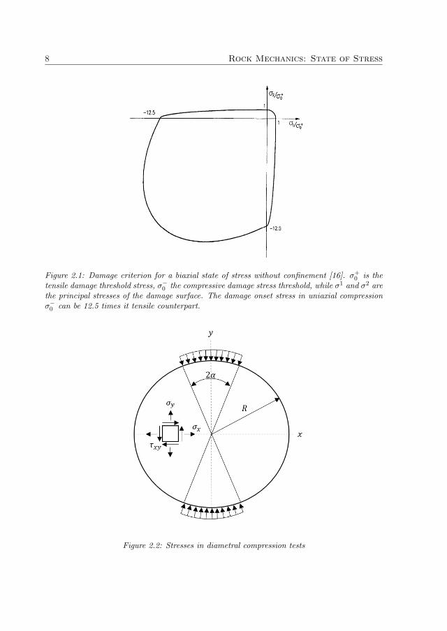
Unequal tensile and compressive strengths are a consequence of the stress-inducedevolution of internal cracks and its strong dependency on the direction of the appliednormal stress. This unequal behavior is characteristic of rock material, where the com-pressive threshold can be larger, more than 10 times, than the tensile limit (see Fig. 2.1).It is important then to characterize both, the tensile and compressive behavior, in orderto get a wide picture of the fracture behavior of the mineral material.
2.1 Diametral Compression Tests
Diametrial compression tests, also known as Brazilian disc tests, are useful to determinethe tensile strength of brittle and quasi-brittle materials due to the difficulty of grippingthe specimen e.g. dog-bone shape, in such way to obtain reproducible data as for astandard tensile test configuration [8]. It is a bi-axial test that consists of compressing athin disc across the diameter under increasing load until failure. In this case, the elasticsolution in a Cartesian coordinate system (x, y), with the origin located at the centerof the disc, is obtained when considering compressive forces of magnitude P along thevertical direction [17, 18].
The stresses are expressed as:
σx(x, y) =2P
πDt− 2P
πt
(x2(R− y)
(x2 + (R− y)2)2+
x2(R + y)
(x2 + (R + y)2)2
)(2.1a)
7
8 Rock Mechanics: State of Stress
Figure 2.1: Damage criterion for a biaxial state of stress without confinement [16]. σ+0 is the
tensile damage threshold stress, σ−0 the compressive damage stress threshold, while σ1 and σ2 are
the principal stresses of the damage surface. The damage onset stress in uniaxial compressionσ−0 can be 12.5 times it tensile counterpart.
Figure 2.2: Stresses in diametral compression tests

2.1. Diametral Compression Tests 9
σy(x, y) =2P
πDt− 2P
πt
((R− y)3
(x2 + (R− y)2)2+
(R + y)3
(x2 + (R + y)2)2
)(2.1b)
τxy(x, y) =2P
πt
(x(R− y)2
(x2 + (R− y)2)2+
x(R + y)2
(x2 + (R + y)2)2
)(2.1c)
where t is the thickness and D the diameter. Accordingly, σx is the normal stressin the perpendicular direction to the loading, σy in the parallel direction, and τxy is theshear stress (see Fig. 2.2).
The compression along the diametral direction induces tensile stresses normal to thevertical diameter which are considered constant over a region around the center (see Eq.(2.1a)). The tensile strength is calculated based on the assumption that failure occursat the center of the disc. Likewise, it is assumed that the friction stresses between theloading platens and the specimen are neglected and that, the material is homogeneous,isotropic and elastic before brittle failure [19]. In addition to this, a distributed load Pover a small area on the circumference can be used in order to prevent premature failure.The maximum tensile stress at the center of the disc is described by Eq. (2.2a) and, aslong as small angles (α) are assumed, Eq. (2.2b) can be considered.
σx(0, 0) =2P
παDt(sin 2α− α) (2.2a)
σx(0, 0) =2P
πDt(2.2b)
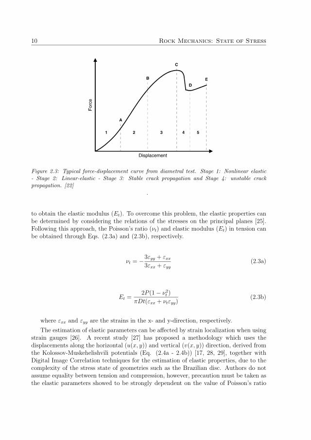
Accounting for the characteristic fracture process of diametral compression tests, ithas been shown that non-linear stages at the beginning of the test, followed by linearelastic deformations, stable crack extension and finally unstable crack propagation (seeFig. 2.3) might be found for load vs. displacement relations [20–22]. In general, during atensile fracture process, the material experiences a stage in which the inelastic behaviordominates the macro-response due to the high activity caused by pre-existing and newlycreated micro-cracks. By an increase of the displacement, a continuous separation ofsurfaces and macro-cracks follows, although the structure is able to support the load.Cohesive effects become relevant until a maximum point is reached and damage extendsbeyond the crack tips [23].
The validity of this test has been discussed for a long time and it depends on thelocation of the crack initiation, as mentioned before. It has been found that the loadingpoint has a great influence on stress concentration and localized strain zone close to theplatens. This affects directly the point of crack initiation and therefore, its propagationpath and failure of the material [24]. Discrepancies between the theoretical analysis andexperimental observations result from the selected failure criteria, besides other influenc-ing factors such as intermediate principal stress, anisotropic nature and heterogeneousmicro-structure [19].
Often, the estimation of material parameters is based on the assumption of equalitybetween tension and compression, so that a unique value of Poisson’s ratio (ν) is used
10 Rock Mechanics: State of Stress
Figure 2.3: Typical force-displacement curve from diametral test. Stage 1: Nonlinear elastic- Stage 2: Linear-elastic - Stage 3: Stable crack propagation and Stage 4: unstable crackpropagation. [22]
.
to obtain the elastic modulus (Et). To overcome this problem, the elastic properties canbe determined by considering the relations of the stresses on the principal planes [25].Following this approach, the Poisson’s ratio (νt) and elastic modulus (Et) in tension canbe obtained through Eqs. (2.3a) and (2.3b), respectively.
νt = −3εyy + εxx3εxx + εyy
(2.3a)
Et =2P (1− ν2
t )
πDt(εxx + νtεyy)(2.3b)
where εxx and εyy are the strains in the x- and y-direction, respectively.
The estimation of elastic parameters can be affected by strain localization when usingstrain gauges [26]. A recent study [27] has proposed a methodology which uses thedisplacements along the horizontal (u(x, y)) and vertical (v(x, y)) direction, derived fromthe Kolossov-Muskehelishvili potentials (Eq. (2.4a - 2.4b)) [17, 28, 29], together withDigital Image Correlation techniques for the estimation of elastic properties, due to thecomplexity of the stress state of geometries such as the Brazilian disc. Authors do notassume equality between tension and compression, however, precaution must be taken asthe elastic parameters showed to be strongly dependent on the value of Poisson’s ratio

2.2. Axial Compression Tests 11
in compression (νc) due to the assumption of proportionality given by
(νtEt
=νcEc
).
u(x, y) = − P
4πµ
{(1− κ) tan−1
(2Rx
x2 + y2 −R2
)+
(1− κ)x
R− 4Rx(R2 − y2 + x2
(R2 + x2 − 2Ry + y2)(R2 + x2 + 2Ry + y2)
} (2.4a)
v(x, y) = − P
4πµ
{(1 + κ)
2ln
(2Rx
x2 + y2 −R2
)+
(1− κ)y
R− 8Rx2y
(R2 + x2 − 2Ry + y2)(R2 + x2 + 2Ry + y2)
} (2.4b)
In general, both experimental and numerical efforts have focused on the analysis of theeffect of contact between the specimen and loading platens, stress analysis in 3D and theeffect of the thickness, deformation and failure of weakening micro-structure, influenceof initiated cracks and their propagation and characterization of material in general.Nevertheless, to the author’s knowledge, information of complex micro-structures suchas slag is missing.
2.2 Axial Compression Tests
The uniaxial compression test (UCT) is widely used to determine the Ultimate Compres-sion Strength (UCS) of rocks. Due to its easy implementation, it is possible to performfurther measurements such as lateral strain, dilatancy or velocity of elastic waves [8].In contrast to the Brazilian disc configuration, the specimen is loaded along the axialdirection of the cylinder and compared to the triaxial compression test, there is no hydrostatic pressure acting on the material. The compressive stress turns to be described byEq. (2.5), where the Ultimate Compressive Strength (UCS) corresponds to its maximumvalue:
σc =P
A0
(2.5)
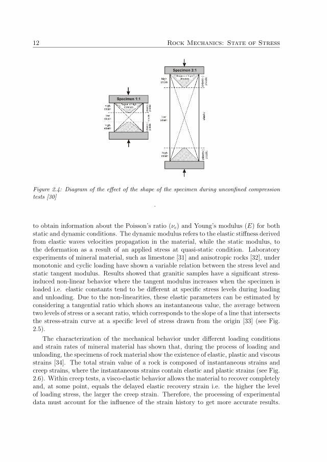
where P is the applied load and A0 the initial cross sectional area.Studies have shown that the results are sensitive to the shape of specimen; a high
stress region is found closer to the loading devices due to friction [30]. A local plasticityeffect is found showing a high strain region, so it is recommendable to work within 2/3of the specimen when analyzing material parameters (see Fig. 2.4).
Studies have focused their efforts in the development of methodologies to characterizethe elastic properties of mineral material. The UCT was introduced due to its versatility
12 Rock Mechanics: State of Stress
Figure 2.4: Diagram of the effect of the shape of the specimen during unconfined compressiontests [30]
.
to obtain information about the Poisson’s ratio (νc) and Young’s modulus (E) for bothstatic and dynamic conditions. The dynamic modulus refers to the elastic stiffness derivedfrom elastic waves velocities propagation in the material, while the static modulus, tothe deformation as a result of an applied stress at quasi-static condition. Laboratoryexperiments of mineral material, such as limestone [31] and anisotropic rocks [32], undermonotonic and cyclic loading have shown a variable relation between the stress level andstatic tangent modulus. Results showed that granitic samples have a significant stress-induced non-linear behavior where the tangent modulus increases when the specimen isloaded i.e. elastic constants tend to be different at specific stress levels during loadingand unloading. Due to the non-linearities, these elastic parameters can be estimated byconsidering a tangential ratio which shows an instantaneous value, the average betweentwo levels of stress or a secant ratio, which corresponds to the slope of a line that intersectsthe stress-strain curve at a specific level of stress drawn from the origin [33] (see Fig.2.5).
The characterization of the mechanical behavior under different loading conditionsand strain rates of mineral material has shown that, during the process of loading andunloading, the specimens of rock material show the existence of elastic, plastic and viscousstrains [34]. The total strain value of a rock is composed of instantaneous strains andcreep strains, where the instantaneous strains contain elastic and plastic strains (see Fig.2.6). Within creep tests, a visco-elastic behavior allows the material to recover completelyand, at some point, equals the delayed elastic recovery strain i.e. the higher the levelof loading stress, the larger the creep strain. Therefore, the processing of experimentaldata must account for the influence of the strain history to get more accurate results.

2.2. Axial Compression Tests 13
Figure 2.5: Diagram of the different ways to estimate the elastic properties from a dependentand independent variable relation. As an example, the Young’s modulus can be estimated fromthe stress-strain relation being the stress the dependent variable and the strain the independentvariable
.
Figure 2.6: Stress-strain relation during multi-level loading and unloading cyclic tests [34]
.
The damage evolution is then a key component in the study of heterogeneous materialsas micro-cracks are intrinsic and random allowing variability of the results that have tobe approached by statistical analyses and considered for oncoming numerical models.

14 Rock Mechanics: State of Stress

Chapter 3
Characterization of RateDependence
Mineral liberation processes involve fracture in multi-level systems.The incorpora-tion of heterogeneity can be performed through stochastic distribution of elastic andstrength parameters; lattice models by varying the size and strength of the bonds; dig-ital image photography to include the actual spatial distribution of mineral grains orVoronoi tessellation techniques to include the mechanical effect of the mineral grains[35]. Understanding this phenomenon requires the characterization of the raw material.Mineralogical and chemical evaluation allows to know more about the structure of thesystem and hence the behavior of the material during comminution.
An extensive work on methodologies to characterize the mechanical behavior of min-eral materials such as granite and concrete has been done by different researchers. Dif-ferent type of tests have been developed by considering, for most of them, the simpleprinciple of homogeneous stress. Two primary measurements obtained from these arethe stress and strain under different loading conditions, which are used for the derivationof constitutive models of both, the micro and macro mechanical behavior of the material.Tests developed to analyze the tensile, compressive and shear response of the system toexternal loading can be performed under quasi-static or dynamic conditions.
Comminution processes require a mechanical characterization of the ore under dif-ferent loading conditions. A great diversity of equipment is available on the market forcrushing processes such as cone crushers, jaw crushers and impact crushers. The maindifference among them is not only the geometrical design, but also the controlling break-age mechanism which is strongly related to the rate of deformation. When real particleswith irregular shapes and not evenly distributed morphology are loaded through smallcontact points, it is possible to identify breakage mechanisms characterized by the threemodes of fracture (tension, compression and shear) [36, 37]. Therefore, when studying thefracture behavior of mineral material, it is valuable to characterize the rate dependenceof the material. The following section presents methodologies to characterize the me-chanical behavior of mineral material keeping in mind its applicability to the calibration
15

16 Characterization of Rate Dependence
and validation of numerical models.
3.1 Quasi-Static Characterization
The creation of new surfaces consumes energy, changing the total energy of the system bythe propagation of induced cracks and suggesting that the heterogeneity of the materialmight be related to its brittleness. Two conditions are crucial when analyzing the crackpropagation and macro-response of this kind of material: the intensity of the availableenergy and the morphology of the crack, particularly the critical length [38]. In order toisolate the events, steady-state conditions shall be implemented so that inertial effectsare negligible
Quasi-static tests are not only useful for the classification of rock material for the eval-uation of properties and applications, but also for increasing knowledge on the fractureprocess and damage evolution. This type of tests are performed at strain rates rangingbetween 10−4 − 10−2 s−1 with electro-mechanical or hydraulic machines equipped withdisplacement transducers that allow controlling the load and time intervals. Accordingto the standard ASTM D7012-14, the axial load shall be applied continuously and, insuch manner, to produce either a stress rate between 0.5-1 MPa/s or a strain rate as con-stant as possible throughout the test [39]. As a result, stress-strain relations are obtainedand mechanical properties such as the unconfined compression strength (UCS) can beestimated.
In this work, two set of experiments were developed: The first set consisted of mono-tonic loading test to obtain information about the Ultimate Tensile Strength (UTS),Ultimate Compressive Strength (UCS), and evolution of both, the strain field and elas-tic properties. Here, the monotonic loading refers to a standard failure test where thesample is loaded continuously until failure is reached. The second set consisted of cyclicloading of Brazilian discs to obtain additional information of behavior of the structureand evolution of damage seen as “degradation” under tensile conditions.
3.1.1 Cyclic Loading
The state of stress of a continuous media can be described by a linear elastic state ofstress (Hooke’s law), although it must be taken into account that brittle material canalso experience temporary or permanent inelastic deformation seen as a hysteric effectoccurring at high levels of stress [40]. These deviations can be a result of the heterogeneityof the material either because of random distributions of inclusions, preferred particleorientation or layered material, just to give some examples. Hence, cyclic loading testsbecome a good way to obtain information about cumulative damage and mechanicalbehavior of the matrix under repetitive loading. There are two loading methods thatcan be used for this purpose [41]: a Systematic loading, where the tests have a constantamplitude or a Damage-controlled, where tests involve an incremental loading amplitude;both can be conducted using a load-controlled or displacement-controlled conditions.
3.2. Dynamic Characterization 17
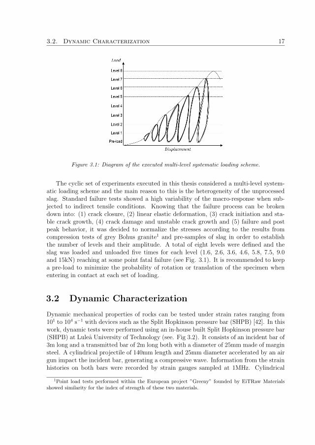
Figure 3.1: Diagram of the executed multi-level systematic loading scheme.
The cyclic set of experiments executed in this thesis considered a multi-level system-atic loading scheme and the main reason to this is the heterogeneity of the unprocessedslag. Standard failure tests showed a high variability of the macro-response when sub-jected to indirect tensile conditions. Knowing that the failure process can be brokendown into: (1) crack closure, (2) linear elastic deformation, (3) crack initiation and sta-ble crack growth, (4) crack damage and unstable crack growth and (5) failure and postpeak behavior, it was decided to normalize the stresses according to the results fromcompression tests of grey Bohus granite1 and pre-samples of slag in order to establishthe number of levels and their amplitude. A total of eight levels were defined and theslag was loaded and unloaded five times for each level (1.6, 2.6, 3.6, 4.6, 5.8, 7.5, 9.0and 15kN) reaching at some point fatal failure (see Fig. 3.1). It is recommended to keepa pre-load to minimize the probability of rotation or translation of the specimen whenentering in contact at each set of loading.
3.2 Dynamic Characterization
Dynamic mechanical properties of rocks can be tested under strain rates ranging from101 to 104 s−1 with devices such as the Split Hopkinson pressure bar (SHPB) [42]. In thiswork, dynamic tests were performed using an in-house built Split Hopkinson pressure bar(SHPB) at Lulea University of Technology (see. Fig 3.2). It consists of an incident bar of3m long and a transmitted bar of 2m long both with a diameter of 25mm made of marginsteel. A cylindrical projectile of 140mm length and 25mm diameter accelerated by an airgun impact the incident bar, generating a compressive wave. Information from the strainhistories on both bars were recorded by strain gauges sampled at 1MHz. Cylindrical
1Point load tests performed within the European project ”Greeny” founded by EiTRaw Materialsshowed similarity for the index of strength of these two materials.

18 Characterization of Rate Dependence
Figure 3.2: Split Hopkinson pressure bar setup complemented with high-speed imaging full-fieldmeasurement system
samples were placed between the incident and the transmitted bars, in such way thatdiametral and axial loading was achieved, depending on the case.
Standard dynamic compressive studies use cylindrical rocks placed in such mannerthat the pulsating waves are able to pass through the axial direction of the specimen.The bars are usually made of steels raging yield strengths of 1750 MPa to achieve a1D elastic wave propagation and a homogeneous deformation of the sample. The timehistories of strain within the sample of the dynamic compression test are obtained fromthe velocities at the interfaces (see Fig. 3.3) given by Eq. (3.1).
v1 = C0(εi − εr) (3.1a)
v2 = C0(εt) (3.1b)
where v1 and v2 are the interfaces between the incident bar-sample and sample-transmitted bar, respectively; εi, εr and εt, the incident, reflected and transmitted pulsesignals and C0 is the longitudinal wave velocity of the bars.
The calculated strain rate of axially loaded samples is given by:
ε(t) =v1 − v2
L=
C0
L(εi − εr − εt) (3.2)
So that the strain during a certain period of time would be,
ε(t) =
∫ t
0
εdt =C0
Ls
∫ t
0
(εi − εr − εt)dt (3.3)
3.2. Dynamic Characterization 19
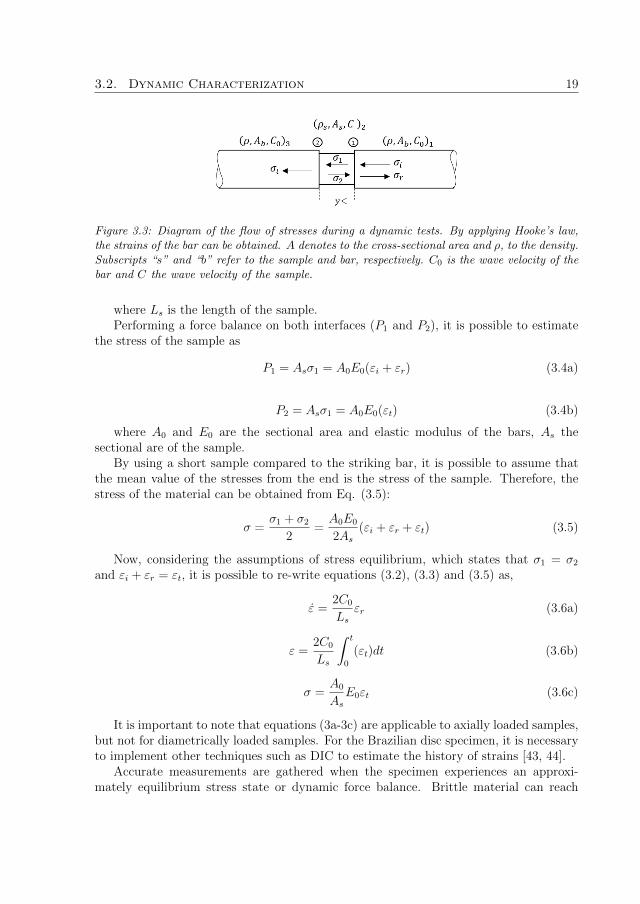
Figure 3.3: Diagram of the flow of stresses during a dynamic tests. By applying Hooke’s law,the strains of the bar can be obtained. A denotes to the cross-sectional area and ρ, to the density.Subscripts “s” and “b” refer to the sample and bar, respectively. C0 is the wave velocity of thebar and C the wave velocity of the sample.
where Ls is the length of the sample.Performing a force balance on both interfaces (P1 and P2), it is possible to estimate
the stress of the sample as
P1 = Asσ1 = A0E0(εi + εr) (3.4a)
P2 = Asσ1 = A0E0(εt) (3.4b)
where A0 and E0 are the sectional area and elastic modulus of the bars, As thesectional are of the sample.
By using a short sample compared to the striking bar, it is possible to assume thatthe mean value of the stresses from the end is the stress of the sample. Therefore, thestress of the material can be obtained from Eq. (3.5):
σ =σ1 + σ2
2=
A0E0
2As
(εi + εr + εt) (3.5)
Now, considering the assumptions of stress equilibrium, which states that σ1 = σ2
and εi + εr = εt, it is possible to re-write equations (3.2), (3.3) and (3.5) as,
ε =2C0
Ls
εr (3.6a)
ε =2C0
Ls
∫ t
0
(εt)dt (3.6b)
σ =A0
As
E0εt (3.6c)
It is important to note that equations (3a-3c) are applicable to axially loaded samples,but not for diametrically loaded samples. For the Brazilian disc specimen, it is necessaryto implement other techniques such as DIC to estimate the history of strains [43, 44].
Accurate measurements are gathered when the specimen experiences an approxi-mately equilibrium stress state or dynamic force balance. Brittle material can reach

20 Characterization of Rate Dependence
failure strain < 0.2%, causing a non-uniform behavior when exposed to high strain rates[45]. Therefore, it is recommendable during dynamic analysis to have a pulse durationat least 10 times larger than the transit time of the longitudinal wave length across thediameter of the bar in order to minimize the dispersion of the propagating pulse [46].
Studies have shown that the peak stress increases with an increase of the loadingrate from quasi-static to dynamic regimes. For materials such as Kota sandstone, thepeak increases at a rate of 13-14% until a strain rate of 1800/s is reached and 25-45%above that level; Dholpur sandstone increases at 10% during the first range and increasesabruptly to 51.47% above 1800/s [43]. In general, there was found a strong correlationbetween the change of the mechanical response of the material when subjected to highstrain-rates and its heterogeneous micro-structure in compressive settings.
In dynamic tests, inertial and wave propagation effects are of great importance [47].Brittle material cannot yield locally increasing the probability of high stress concentra-tions due to poor flatness of the contact surfaces, misalignment of the bars and indenta-tion of the specimen caused when testing stiff materials [48]. In addition, it is importantto consider pulse shaping techniques to minimize the effects of dispersion and obtaindynamic equilibrium of the sample. The main reason to this is to decrease the inertialeffects that might be induced by the stress wave, as well as the high-frequency oscillations[49].
In light of the validity of the dynamic tests, a step-by-step methodology is recom-mended. This can be summarized as follows:
1. Dynamic experiment: the selection of configurations to be tested (e.g. diametricallyor axially loaded samples), external conditions (e.g. confinement, temperature, con-tact conditions, etc), as well as the data acquisition system (software and hardware)such as strain gauges and the high speed camera.
2. Specimen design: it is known from literature that the slenderness ratio of the sampleis related to inertial effects which can induce premature failure. The recommendedratio for Brazilian disc samples is L/D ≈ 0.5, while for UCT, L/D ≤ 1 [50].
3. Calibration of the system: selection of the magnitude and shape of the input signal,correction of dispersion and management of the intensity of the output signal.
Considering the heterogeneity of the material and, in order to minimize sources of errorfrom the experimental set up, special emphasis was made on the calibration of the system.The following section presents the methodology implemented for the calibration of theSHPB system.
3.2.1 Calibration of the SHPB
In this study, the calibration of the system was performed using a semi closed-loopfeedback technique due to the limited amount of specimens available. The semi closed-loop feedback (see Figure 3.4) started by selecting the striker and establishing an initialimpact velocity considering the stress of the incident bar given by Eq. (3.7) [51].

3.2. Dynamic Characterization 21
Figure 3.4: Semi closed-loop feedback technique used for the calibration of the system
σi =1
2ρbarcbarV (3.7)
and the duration of the pulse given by Eq. (3.8)
∆t =2lscbar
(3.8)
where ρbar is the mass density of the incident bar, cbar, the elastic longitudinal stresswave velocity of the bar (cbar =
√Ebar/ρbar) and V the velocity of the striker; Ebar the
Young’s modulus of the bar, and ls the length of the striker.Once the striker and velocity were defined, a set of two blank tests were performed
to check the incident, reflected and transmitted pulses. The first blank test was a free-end reflection with the main objective of identifying any phase delay of the incident andreflective pulses and checking the shape of the incident pulse. The second blank test wasan input-output bar configuration without specimen which allowed to measure the strainwave velocity and energy losses of the system.
Afterwards, a dummy material is tested using the same parameters. In this case, twowell-studied dummy materials were used: grey Bohus granite and diabase. The main rea-son to working with these materials is the availability of information in literature abouttheir mechanical behavior to compare with. Besides, they are characterized for havingdifferent micro-structural features, where the grey Bohus granite has larger grains com-pared to the well-packed diabase, giving different mechanical responses when subjected

22 Characterization of Rate Dependence
to time-dependent loads. Thus, the database of signals and parameters would have beingfed with counterpart mechanical responses, allowing to interpolate data to test the slag.
The signals from these tests were analyzed along with of the high speed digital images(see Chapter 4) in order to check the amplitude of the signal and response to rising timewhich was also compared to the digital images to identify the type of fracture (singlefracture, multiple fracture or crushing). If the results were not satisfactory, the param-eters were modified, the blank tests were performed once again and then the dummymaterial was tested. This loop was performed until enough data was collected for bothdummy materials. These baselines work not only to calibrate the system, but also tofeed a database of signals to test heterogeneous material such as slag.
Chapter 4
Digital Image Correlation
Most of the mechanical tests to characterize the behavior of materials are based on theconstitutive relation stress-strain. Tensile and compression tests are used to determinematerial parameters such as the Poisson’s ratio and Young’s modulus, among others.These tests require the measurement of displacements and load in order to transformthose values into stress and strains. Strain gauges are often mounted on the specimensto determine the deformation under loading.
The Digital Image Correlation (DIC) is a method to calculate the displacement anddeformation by analyzing full-field images. The main advantage of this method is thevirtual independence to the geometry, size, material or deformation rate of the speci-men. DIC techniques have been used to analyze complex materials such as composites,biological e.g. bones, and heterogeneous brittle materials when global data, acquired byin-situ techniques, is not enough. Local data is needed to calibrate and validate complexmechanical behavior when the system undergoes plastic deformations or reaches failureunder steady or cyclic loading [52, 53].
The application of digital image correlation to determine the mechanical properties ofrock materials was initially proposed by Chu et al. [54] taking as a basis the theory of de-formation. The method consists of taking a series of images of the surface of interest andperforming a triangulation of homologous identified points via facets. Reference pointsare allocated to identify individual areas of the stochastic image information. Softwareslike ARAMIS® and GOM Correlate® use adaptive approaches under the assumptionthat casual connections exist between the original state and deformed state (Eq. (4.1a)).Therefore a correlation function c(∆x,∆y) (Eq. (4.1b)) provides a rate of similarity oftwo signals f(x, y) and g(xt, yt) [55].
f(x, y) ↔ g(xt, yt) (4.1a)
c(∆x,∆y) =f(x, y), g(x+∆x, y +∆y)
| f(x, y) | · | g(x, y) |(4.1b)
When it comes to the analysis of rock material, it is important to consider the brittlenature of the system. A possible application of this method is the study of the crack
23

24 Digital Image Correlation
(a)
(b)
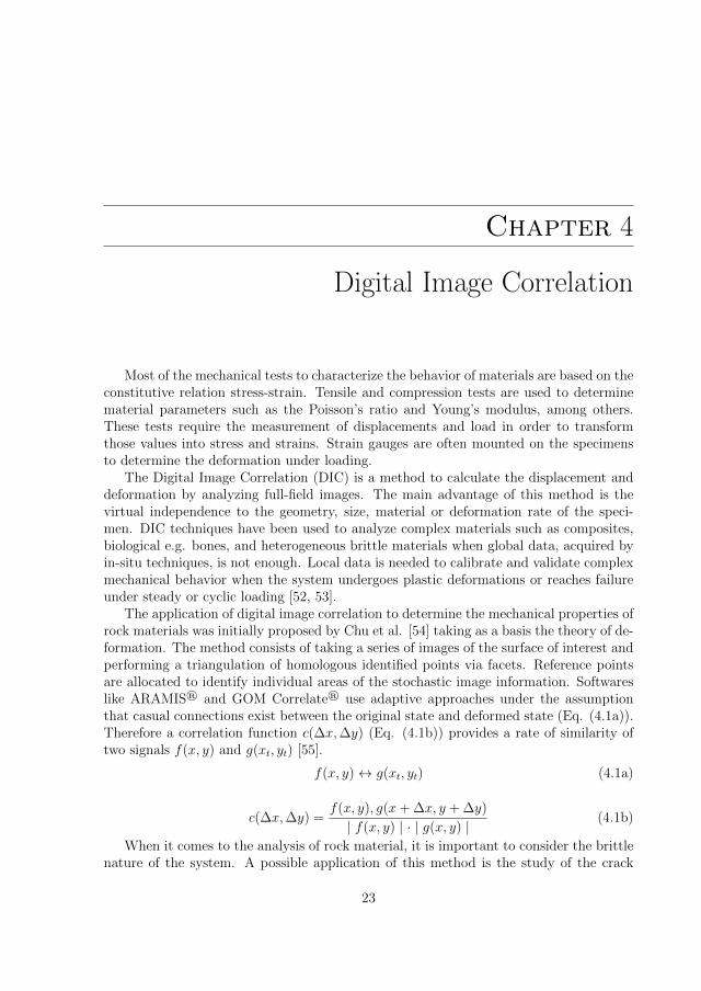
Figure 4.1: Region of Interest (ROI) of (a) Brazilian disc specimens and (b) unconfined axiallyloaded specimens
growth behavior, damage evolution and deterioration of observable macroscopic materialparameters. Comparisons of the results from studies of the crack propagation character-istics of mineral material by means of crack propagation gauges (CPG) and digital imagecorrelation have shown that the independence of the DIC to the geometry and materialallows to get reliable information when considering a strain threshold of 2-3% [56]. Onthe other hand, the quantification of the relation between the tensile damage and straingradients during quasi-static conditions by means of uniaxial tension test of granite usinga dog-bone geometry revealed valuable information regarding strain localization bandsduring the stages prior to failure [57]. DIC has also been used to obtain the displacementfield on the surface of a Brazilian disc specimen during loading, unloading and failurestages to estimate elastic parameters [17]. This methodology, implemented initially onthe elastic material, gives a basis for working with DIC for the study of brittle mate-rial to obtain material parameters such as the elastic modulus and Poisson’s ratio forboth, plane stress and plane strain formulations, and to establish a failure criterion ofheterogeneous material with complex states of stress.
Nonetheless, it is important to highlight that the accuracy of the data is stronglydependent of the correlation parameters. Strains are sensitive to the size and the dis-tance between facets. An investigation of the influence of the transverse anisotropy andorientation of the planes of rock samples when subjected to diametrial compression teststhrough DIC and strain gauges showed that the correlation is more sensitive to the sizeof the facet than to the spacing [58]. Additional factors to be taken into account are thedensity and size of the speckles [59], step size and strain window size [60] and adherenceto the material surface. In high velocity tests, it is necessary to take images with ahigh speed camera to capture the crack initiation point and propagation during loading[61]. Factors such as the maximum frame rate, exposure time resolution, lightening, and

25
resolution [62] must be taken into account in addition to the ones stated before.Adding together the previous information, it was decided to take images at 1-2 fps
for quasi-static tests, while dynamic Brazilian disc at 663,200 fps and dynamic axial testsat 380,000 fps. The post-process was performed with the integrated software from GOMAramis Digital Correlation systems (GOM mbH, Germany). Aramis v6 series uses thestochastic image information adjusted by size and distance between them to obtain areasof control called facets. The strain value of the center point of a rectangular field givesinformation about the evolution of the damage for the samples. The strain field givesinformation about local data, although to determine the elastic properties of the materialis necessary to synthesize the information into a global value. Global information wasobtained by averaging local data from the region of interest (ROI) for each time step (seeFig. 4.1) allowing to reduce the effect of strain localization. The ROI was defined byan effective area with a length ranging between 65-80% of the diameter accounting forthe brittle behavior of the material under tension and considering the theory of centralcrack initiation [25] for Brazilian disc tests. In both Brazilian disc and axial tests, theROI tries to minimize the probability of selecting high strain regions close to the contactpoints.

26 Digital Image Correlation

Chapter 5
Summary of Appended Papers
The work was aimed to increase the knowledge of the mechanical behavior of unpro-cessed slag and feed future numerical models. As a result of the study of unprocessedslag, two papers were written:
5.1 Paper A
Summary: This work is a study of the mechanical behavior of unprocessed manganeseslag under quasi-static conditions considering a simple loading scheme. Specimens fromcore material were classified, prepared and tested with an electro-mechanical loading ma-chine together with digital photography. Samples were loaded diametrically and axiallyunder controlled monotonic and cyclic conditions. For the cyclic tests, the evolution ofdamage was recorded and analyzed by digital correlation techniques. History of strainfields were used to reconstruct stress-strain curves, for axially loaded specimens, and load-strain curves, for Brazilian discs. Representative results from axially loaded samples fromdifferent categories were chosen to estimate the elastic properties of the material undercompression, while one single representative Brazilian disc was used for tensile condi-tions. This considering that the estimation of the elastic parameters can be performedas long as the strain field is similar to the analytical solution, where the load-strain curveshows a proportional dependence and brittle behavior. Degradation of the material underrepetitive loading and its effect on the elastic modulus was also investigated. Generalresults exposed a mechanical behavior of composite-like material where random failureof the components caused high variability of the elastic parameters.
Relation to thesis: The paper investigates a highly heterogeneous material giving aninsight of methodologies and challenges when manufacturing samples, testing them underquasi-static conditions by means of simple loading schemes and, processing mechanicaland optical data. Increased knowledge of the estimation of elastic properties of brittlematerials under compression and tension was also achieved.
27

28 Summary of Appended Papers
5.2 Paper B
Summary: This work is a study of the mechanical response of unprocessed manganeseslag subjected to time-dependent loads. Full-field deformations and evolution of fracturewere captured by 2D high speed digital image correlations techniques. Pulse shapingtechniques were implemented to impact axially and diametrically slag samples. Historyof strain fields were used to reconstruct stress-strain curves, for axially loaded specimens,and load-strain curves, for Brazilian discs. Different stages of fracture were identifiedand correlated to digital images, so that information of the crack initiation and evolutionof damage was obtained. Critical points such as the onset of fracture point, fractureand maximum stress were correlated and analyzed, with the aim of capturing an overallperspective of the macro-response. Two dominant mechanisms of energy dissipationwere identified via Brazilian disc tests, as well as the crack propagation path for sampleswith a high amount of inclusions. A highly dependent behavior on the composition andstructure of the specimen was perceived. In general, results exposed a good insight ofthe mechanical-behavior of the material, although internal events and contributions ofinertial effects to non-uniform deformations were present.Relation to thesis: The paper investigates the macro-response of highly heterogeneousmaterials subjected to time-dependent loads. This allowed to increase the knowledge onthe calibration of the Split Hopkinson pressure bar machine, dynamic testing of brittlecomposite-like materials and post-processing of the data. In addition, relevant informa-tion to the processing and crushing regarding the rate-dependent behavior of slag wasacquired.

Chapter 6
Conclusions and Outlook
A wide range of studies have being applied to the characterization of the fractureprocess i.e evolution of damage and crack propagation for brittle materials. Parameterssuch as Young’s modulus, Poisson’s ratio and ultimate strengths have been of interest,as well, due to their applicability to material models used for finite element formulationsand for the estimation of micro-parameters using discrete approximations. The latesttrend within optimization techniques is the implementation of multi-scale models, wheresubsystems are analyzed separately and coupled by homogenization frameworks. Thesenumerical models go by the hand of experimental techniques as they give the baseline ofknowledge to model the material and its interaction with the environment.
Researchers have spent time understanding, analyzing and characterizing the me-chanical behavior of mineral material such as granite and limestone by numerical andexperimental techniques. Although, information about the mechanical behavior of het-erogeneous brittle material such as unprocessed slag is lacking.
This thesis focused on the mechanical characterization of unprocessed slag which ishighly heterogeneous not only in structure but also in composition. Figure 6.1 presentsthe methodology implemented in this work. After the development of the experimentalprocedure, quasi-static and dynamic tests of manganese slag sample loaded axially anddiametrically were performed to obtain information about the behavior under compres-sion and indirect tension. The history of strains was recorded by optical techniques inorder to have a global perspective of the development of the deformation field by havingaccess to local information on the surface of the specimen. It is also important to high-light that great part of the manufacturing process was performed at Lulea Universityof Technology and it consisted of classifying, drilling, cutting, polishing, sandblasting,painting and obtaining physical properties for each sample.
Quasi-static tests were performed with an open system configuration under simpleloading schemes in order to have information about the evolution of damage. The maingoal for using a monotonic loading was to investigate on the load-strain relation, ultimatetensile strength and elastic parameters such as the Poisson’s ratio and elastic modulus.From indirect tensile tests, a stiffness modulus was estimated which, combined with cyclic
29

30 Conclusions and Outlook
loading results, allowed to obtain data about the degradation of the material and macro-response when subjected to repetitive loading. Particularly, the execution under bothconfigurations exposed not only a bi-modularity of the slag, but also a variable Poisson’sratio under tensile conditions dependent on the load. Detailed results of this study arepresented in Paper A.
On the other hand, dynamic tests were performed using an in-house built SHPB. Anextensive calibration of the system consisting of selection of the velocity of the projectile,intensity and shape of the input signal and correction of dispersion by means of pulseshaping techniques and testing of dummy materials was performed to normalized theexperiments and control the reproducibility of the tests. Results showed that strain his-tories are a good indicator of the evolution of damage of the material although internalevents take place inducing non-uniform deformation of the matrix. It was also remarkablethe predominance of two mechanisms of fracture under tensile conditions: fragmentationand splitting. Detailed results of this study are presented in Paper B.
The major outcomes from this work, and according to the research questions, are:How does unprocessed slag behave at different loading conditions?
• The evolution of the strain captured by digital image correlation techniques isevidence of mechanical behavior of composite-like material where the random failureof the components cause dispersion of the data.
• The major insight from the rate-dependence relation was that the material tendsto increase its fracture strength as the rate of deformation increases.
What are the factors governing the macro-response and damage evolution of slag?
• Compression of manganese slag samples resulted in three main mechanical re-sponses for both Brazilian disc and axial samples tests, which are highly correlatedto the structure and composition of the material
• A great dependency of the strength to the inclusion density, distribution and levelof attachment to the matrix was found.
A macroscopic view of fracture behavior of a highly heterogeneous material was ob-tained from local information of the surface of the specimens by means of innovativetechniques and simple loading schemes. Having in mind the importance of numericalmodels for the optimization of comminution processes, future work shall be focused onthe development of models using as a baseline data and knowledge acquired from thisthesis.

31
Figure 6.1: Methodology implemented in the thesis for the testing and analysis of heterogeneousmaterial

32 Conclusions and Outlook

References[1] V. Golik, V. Komashchenko, V. Morkun, N. Morkun, and S. Hryshchenko. “Energy
Saving in Mining Production”. In: Science and innovation 14.3 (2018), pp. 29–39.
[2] J. Jeswiet and A. Szekeres. “Energy Consumption in Mining Comminution”. In:2016.
[3] D. Tromans. “Mineral comminution: Energy efficiency considerations”. In: Miner.Eng. 21.8 (July 2008), pp. 613–620.
[4] M. S. Powell and R. D. Morrison. “The future of comminution modelling”. In:International Journal of Mineral Processing 84.1-4 (2007), pp. 228–239.
[5] R. King. “Comminution research - a success story that has not yet ended”. In:Proceedings XVIII Int Min Proc Congress. Vol 1. Sydney: AUSIMM, 1993, pp. 39–45.
[6] J. Terva, K. Valtonen, P. Siitonen, and V.-t. Kuokkala. “Correlation of wear andwork in dual pivoted jaw crusher tests”. In: Journal of Engineering Tribology 234.3(2020), pp. 334–349.
[7] M. Lindqvist and C. M. Evertsson. “Linear wear in jaw crushers”. In: MineralsEngineering 16.1 (Jan. 2003), pp. 1–12.
[8] M. S. Paterson and Teng-fong Wong. Experimental Rock Deformation - The BrittleField. 2nd Editio. The Netherlands: Springer Berlin Heidelberg, 2005.
[9] L. Holappa, M. Kekkonen, A. Jokilaakso, and J. Koskinen. “A Review of CircularEconomy Prospects for Stainless Steelmaking Slags”. In: Journal of SustainableMetallurgy 2021 7:3 7 (3 June 2021), pp. 806–817.
[10] N. S. Association. Common Uses for Slag. Tech. rep. Coatesville , PA: NationalSlag Association.
[11] A. G. Vayghan, L. Horckmans, R. Snellings, A. Peys, P. Teck, J. Maier, B. Friedrich,and K. Klejnowska. “Use of treated non-ferrous metallurgical slags as supplemen-tary cementitious materials in cementitious mixtures”. In: Appl. Sci. 11.9 (2021).
[12] M. Hesse, O. Popov, and H. Lieberwirth. “Increasing efficiency by selective com-minution”. In: Minerals Engineering 103-104 (Apr. 2017), pp. 112–126.
[13] L. G. Leon, K. Johan Hogmalm, and Magnus Bengtsson. “Understanding MineralLiberation during Crushing”. In: Minerals 10.164 (2020), pp. 1–20.
33

34 References
[14] M. Lindroos, T. Andersson, A. Laukkanen, L. Suarez, J. Kajberg, P. Jonsen, J.Terva, and M. Kallio. “Micromechanical and multi-scale modeling of manganesecontaining slag comminution in the design of energy efficient secondary raw materialbene ciation processes”. In: Preprint submitted to Minerals Engineering (2020),pp. 1–38.
[15] H. Xie and F. Gao. “The mechanics of cracks and a statistical strength theoryfor rocks”. In: International Journal of Rock Mechanics and Mining Sciences 37.3(2000), pp. 477–488.
[16] V. a. Lubarda, D. Krajcinovic, and S. Mastilovic. “Damage model for brittle elasticslids with unequal tensile and comopressive strengths”. In: Engineering FracrureMechrmics 49.5 (1994), pp. 681–697.
[17] C. Liu and M.L. Lovato. “Elastic Constants Determination and Deformation Ob-servation Using Brazilian Disk Geometry”. In: Proceedings of the XIth InternationalCongress and Exposition. 7. Orlando, Florida USA: Society for Experimental Me-chanics Inc, 2008, pp. 1025–1039.
[18] P. Jonsen, H. A. Haggblad, and K. Sommer. “Tensile strength and fracture energyof pressed metal powder by diametral compression test”. In: Powder Technology176.2-3 (2007), pp. 148–155.
[19] D. Li and L. N. Y. Wong. “The brazilian disc test for rock mechanics applications:Review and new insights”. In: Rock Mechanics and Rock Engineering 46.2 (2013),pp. 269–287.
[20] P. Jonsen. “Fracture and Stress in Powder Compacts”. PhD thesis. Lulea tekniskauniversitet, 2006.
[21] M. Cai. “Fracture Initiation and Propagation in a Brazilian Disc with a PlaneInterface: a Numerical Study”. In: Rock Mechanics and Rock Engineering 201246:2 46 (2 Nov. 2012), pp. 289–302.
[22] P. Jonsen, H. A. Haggblad, and K. Sommer. “Tensile strength and fracture energy ofpressed metal powder by diametral compression test”. In: Powder Technol. 176.2-3(2007), pp. 148–155.
[23] J. F. Labuz, S. P. Shah, and C. H. Dowding. “MEASUREMENT AND DESCRIP-TION OF TENSILE FRACTURE IN GRANITE”. In: J. Eng. Mech. 115 (9 1989),pp. 1935–1949.
[24] V. J. Garcıa, C. O. Marquez, A. R. Zuniga-Suarez, B. C. Zuniga-Torres, andL. J. Villalta-Granda. “Brazilian Test of Concrete Specimens Subjected to Dif-ferent Loading Geometries: Review and New Insights”. In: Int. J. Concr. Struct.Mater. 11.2 (2017), pp. 343–363.
[25] G. Hondros. “The evaluation of Poisson’s ratio and the modulus of materials of lowtensile resistance by the Brazilian (Indirect tensile) test with particular referenceto concrete”. In: Aust. J. Appl. Sci. 10.3 (1959), pp. 243–268.

References 35
[26] H. Munoz, A. Taheri, and E. K. Chanda. “Pre-Peak and Post-Peak Rock StrainCharacteristics During Uniaxial Compression by 3D Digital Image Correlation”.In: Rock Mech. Rock Eng. 49.7 (2016), pp. 2541–2554.
[27] S. Patel and C. D. Martin. “Evaluation of Tensile Young’s Modulus and Poisson’sRatio of a Bi-modular Rock from the Displacement Measurements in a BrazilianTest”. In: Rock Mech. Rock Eng. 51.2 (2018), pp. 361–373.
[28] S. Roux, F. Hild, and S. Pagano. “A stress scale in full-field identification proce-dures: A diffuse stress gauge”. In: European Journal of Mechanics, A/Solids 24.3(2005), pp. 442–451.
[29] F. Hild and S. Roux. “Digital image correlation: From displacement measurementto identification of elastic properties - A review”. In: Strain 42.2 (2006), pp. 69–80.
[30] K. Thuro, R. J. Plinninger, S. Zah, and S. Schutz. “Scale effects in rock strengthproperties. Part 1: Unconfined compressive test and Brazilian test”. In: ISRM Re-gional Symposium, 3-7 June (2001), pp. 169–174.
[31] N. A. Al-Shayea. “Effects of testing methods and conditions on the elastic propertiesof limestone rock”. In: Eng. Geol. 74.1-2 (2004), pp. 139–156.
[32] M. Nejati, M. L. T. Dambly, and M. O. Saar. “A methodology to determine theelastic properties of anisotropic rocks from a single uniaxial compression test”.In: Journal of Rock Mechanics and Geotechnical Engineering 11.6 (Dec. 2019),pp. 1166–1183.
[33] L. Dong, H. Xu, P. Fan, and Z. Wu. “On the Experimental Determination ofPoisson’s Ratio for Intact Rocks and Its Variation as Deformation Develops”. In:Adv. Civ. Eng. 2021 (2021), pp. 1–10.
[34] Y. Li and C. Xia. “Time-dependent tests on intact rocks in uniaxial compression”.In: International Journal of Rock Mechanics and Mining Sciences 37.3 (Apr. 2000),pp. 467–475.
[35] O. K. Mahabadi, B. S. Tatone, and G. Grasselli. “Influence of microscale hetero-geneity and microstructure on the tensile behavior of crystalline rocks”. In: Journalof Geophysical Research: Solid Earth 119.7 (2014), pp. 5324–5341.
[36] B. A. Wills and J. A. Finch. Wills’ mineral processing technology: An introductionto the practical aspects of ore treatment and mineral recovery. Elsevier Inc., 2015,pp. 1–498.
[37] V. Hajiabdolmajid, P. K. Kaiser, and C. D. Martin. “Modelling brittle failure ofrock”. In: Int. J. Rock Mech. Min. Sci. 39.6 (2002), pp. 731–741.
[38] P. Semsari Parapari, M. Parian, and J. Rosenkranz. “Breakage process of mineralprocessing comminution machines - An approach to liberation”. In: Adv. PowderTechnol. 31.9 (2020), pp. 3669–3685.
[39] A. International. D7012-14: Standard test method for compressive strength andelastic moduli of intact rock core specimens under varying states of stress and.Tech. rep. February. ASTM, 2004, pp. 4–11.

36 References
[40] N. Burdine. Rock Failure Under Dynamic Loading Conditions. 1963.
[41] R. Shirani Faradonbeh, A. Taheri, and M. Karakus. “Post-peak behaviour of rocksunder cyclic loading using a double-criteria damage-controlled test method”. In:Bull. Eng. Geol. Environ. 80 (2021), pp. 1713–1727.
[42] S. Nemat-nasser and S. Diego. “Introduction to High Strain Rate Testing”. In:ASM Handb. Vol. 8. 2000, pp. 427–428.
[43] B. K. Mishra and C. V. Murty. “On the determination of contact parameters forrealistic DEM simulations of ball mills”. In: Powder Technology 115.3 (Apr. 2001),pp. 290–297.
[44] J. Kajberg and K. G. Sundin. “Material characterisation using high-temperatureSplit Hopkinson pressure bar”. In: J. Mater. Process. Technol. 213.4 (2013), pp. 522–531.
[45] K. Xia, F. Dai, and R. Chen. “Split Hopkinson pressure bar tests of rocks”. In:Advances in Rock Dynamics and Applications May (2011), pp. 35–77.
[46] G. Subhash. “Split-Hopkinson Pressure Bar Testing of Ceramics Review of Tradi-tional Split-Hopkinson Pressure Bar Operational Principles”. In: 8 (2000), pp. 497–504.
[47] Q.B Zhao and J. Zhang. “A Review of Dynamic Experimental Techniques andMechanical Behaviour of Rock Materials Compact tension Direct tension”. In: RockMech Rock Eng 47 (2014), pp. 1411–1478.
[48] W. W. Chen and B. Song. Split Hopkinson (Kolsky) Bar: Design, Testing andApplications. Mechanical. Boston, MA: Springer, 2011.
[49] F. Dai, S. Huang, K. Xia, and Z. Tan. “Some Fundamental Issues in DynamicCompression and Tension Tests of Rocks Using Split Hopkinson Pressure Bar”. In:Rock Mech Rock Eng 43 (2010), pp. 657–666.
[50] B. A. Gama, S. L. Lopatnikov, and J. W. Gillespie. “Hopkinson bar experimentaltechnique: A critical review”. In: Appl. Mech. Rev. 57.1-6 (2004), pp. 223–250.
[51] Z. G. Wang and L. W. Meyer. “On the Plastic Wave Propagation Along the Spec-imen Length in SHPB Test”. In: Exp. Mech. 50 (2010), pp. 1061–1074.
[52] A. S. Dickinson, A. C. Taylor, H. Ozturk, and M. Browne. “Experimental Validationof a Finite Element Model of the Proximal Femur Using Digital Image Correlationand a Composite Bone Model”. In: Journal of Biomechanical Engineering 133.1(Dec. 2010).
[53] J. Montesano, M. Selezneva, M. Levesque, and Z. Fawaz. “Modeling fatigue dam-age evolution in polymer matrix composite structures and validation using in-situdigital image correlation”. In: Composite Structures 125 (July 2015), pp. 354–361.
[54] T. C. Chu, W. F. Ranson, and M. A. Sutton. “Applications of digital-image-correlation techniques to experimental mechanics”. In: Experimental Mechanics25.3 (1985), pp. 232–244.

References 37
[55] GOM GmbH. GOM Testing: Technical Documentation as of V8 SR1. Tech. rep.Germany: GOM Gmhb, 2016, pp. 1–30.
[56] M. Ju, J. Li, Q. Yao, X. Li, and J. Zhao. “Rate effect on crack propagation mea-surement results with crack propagation gauge, digital image correlation, and visualmethods”. In: Engineering Fracture Mechanics 219 (Oct. 2019), p. 106537.
[57] G. Yang, Z. Cai, X. Zhang, and D. Fu. “An experimental investigation on the dam-age of granite under uniaxial tension by using a digital image correlation method”.In: Optics and Lasers in Engineering 73 (Oct. 2015), pp. 46–52.
[58] Z. Aliabadian, G. F. Zhao, and A. R. Russell. “Crack development in transverselyisotropic sandstone discs subjected to Brazilian tests observed using digital imagecorrelation”. In: International Journal of Rock Mechanics and Mining Sciences119.May (2019), pp. 211–221.
[59] G. Crammond, S. W. Boyd, and J. M. Dulieu-Barton. “Speckle pattern qualityassessment for digital image correlation”. In: Optics and Lasers in Engineering 51(12 Dec. 2013), pp. 1368–1378.
[60] Y. Wang, P. Lava, S. Coppieters, M. D. Strycker, P. V. Houtte, and D. Debruyne.“Investigation of the Uncertainty of DIC Under Heterogeneous Strain States withNumerical Tests”. In: Strain 48 (6 Dec. 2012), pp. 453–462.
[61] M. Sharafisafa and L. Shen. “Experimental Investigation of Dynamic Fracture Pat-terns of 3D Printed Rock-like Material Under Impact with Digital Image Corre-lation”. In: Rock Mechanics and Rock Engineering 2020 53:8 53 (8 Apr. 2020),pp. 3589–3607.
[62] P. L. Reu and T. J. Miller. “The application of high-speed digital image correla-tion”. In: J. Strain Anal. Eng. Des. 43.8 (2008), pp. 673–688.

38 References

ISSN 1402-1757ISBN 978-91-7790-936-1 (print)ISBN 978-91-7790-937-8 (pdf )
Luleå University of Technology 2021
Laura Suarez Collazos M
echanical Characterization of H
eterogeneous Brittle M
aterials
Department of Engineering Sciences and MathematicsDivision of Solid Mechanics
Print: Lenanders Grafiska, 139870


