91
ERT 313 : BIOSEPARATION ENGINEERING Mechanical - Physical Separation Process
ERT 313 :
BIOSEPARATION ENGINEERING
Mechanical - Physical Separation Process
Students should be able to;
APPLY and CALCULATE based on
filtration principles; ANALYZE cake
filtration, Constant Pressure Filtration,
Continuous Filtration and Constant Rate
Filtration.
Introduction
• Filtration is a solid-liquid separation where the
liquid passes through a porous medium to remove
fine suspended solids according to the size by
flowing under a pressure differential.
• The main objective of filtration is to produce high-
quality drinking water (surface water) or high-
quality effluent (wastewater)
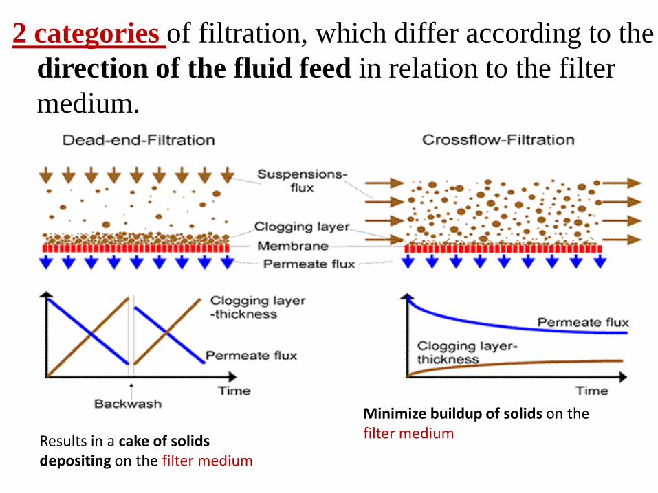
2 categories of filtration, which differ according to the
direction of the fluid feed in relation to the filter
medium.
Results in a cake of solids depositing on the filter medium
Minimize buildup of solids on the filter medium
Application of Filtration in
Bio-industry
Recovery of crystalline solids
Recovery of cells from fermentation medium
Clarification of liquid and gasses
Sterilization of liquid for heat sensitive compound
Filtration Equipment
Filtration for biological materials is generally completed using batch filtration, rotary drum filtration, or ultrafiltration methods.
1. Batch Filtration
• Usually performed under constant pressure with a pump that moves the broth or liquor through the filter
• Filter cake will build-up as filtration proceeds and resistance to broth flow will increase
• The filter press is the typical industrial version of a batch vacuum filter, using a plate and frame arrangement
• Can be used to remove cells, but does not work particularly well for animal cell debris or plant seed debris
Cont….Filtration Equipment
2. Rotary Drum Filtration
• Rotary vacuum filters can be used to efficiently remove mycelia, cells, proteins, and enzymes, though a filter aid or precoat of the septum may be necessary
3. Ultrafiltration
• Utilizes a membrane to separate particles that are much larger than the solvent used
• Successful removal occurs in the partical size range of 10 solvent molecular diameters to 0.5 μ
Filter Media • To act as an impermeable barrier for particulate matter.
• Filtration media for cross-flow filtration are generally referred as “MEMBRANE”
• First and foremost, it must remove the solids to be filtered from the slurry and give a clear filtrate
• Also, the pores should not become plugged so that the rate of filtration becomes too slow
• The filter medium must allow the filter cake to be removed easily and cleanly
• Some widely used filter media (for conventional filtration) like filter paper, ceramics, synthetic membrane, sinterd & perforated glass, woven materials (woven polymer fiber).
Filter Aids
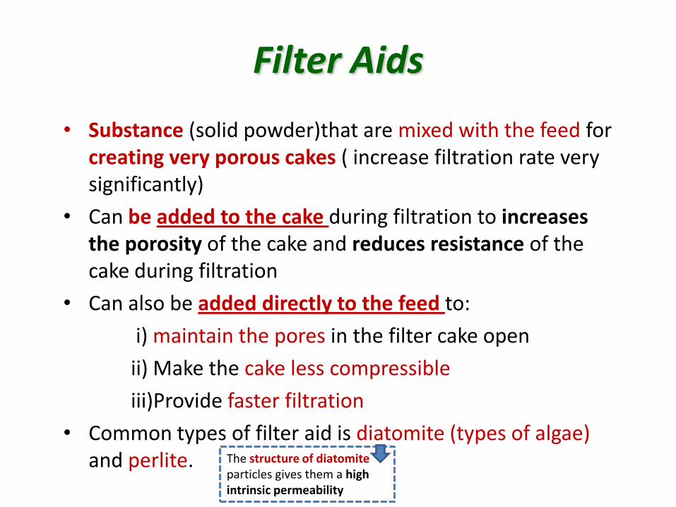
• Substance (solid powder)that are mixed with the feed for creating very porous cakes ( increase filtration rate very significantly)
• Can be added to the cake during filtration to increases the porosity of the cake and reduces resistance of the cake during filtration
• Can also be added directly to the feed to:
i) maintain the pores in the filter cake open
ii) Make the cake less compressible
iii)Provide faster filtration
• Common types of filter aid is diatomite (types of algae) and perlite.
The structure of diatomite particles gives them a high intrinsic permeability
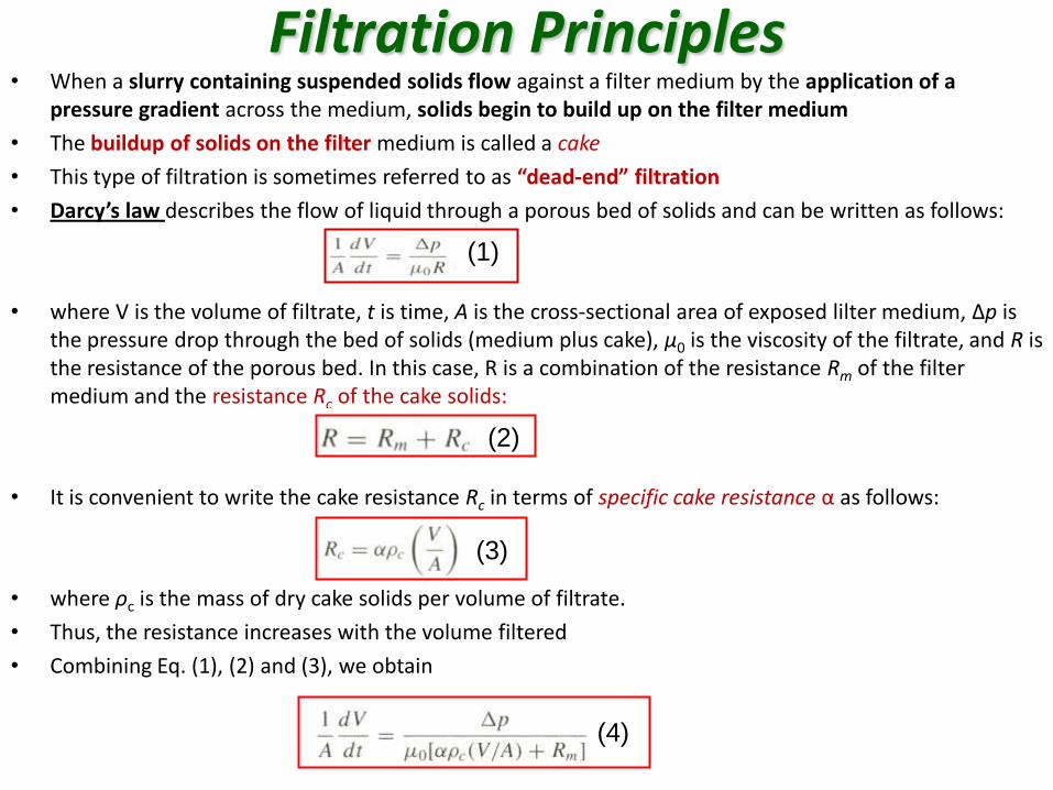
Filtration Principles • When a slurry containing suspended solids flow against a filter medium by the application of a
pressure gradient across the medium, solids begin to build up on the filter medium
• The buildup of solids on the filter medium is called a cake
• This type of filtration is sometimes referred to as “dead-end” filtration
• Darcy’s law describes the flow of liquid through a porous bed of solids and can be written as follows:
• where V is the volume of filtrate, t is time, A is the cross-sectional area of exposed lilter medium, Δp is the pressure drop through the bed of solids (medium plus cake), µ0 is the viscosity of the filtrate, and R is the resistance of the porous bed. In this case, R is a combination of the resistance Rm of the filter medium and the resistance Rc of the cake solids:
• It is convenient to write the cake resistance Rc in terms of specific cake resistance α as follows:
• where ρc is the mass of dry cake solids per volume of filtrate.
• Thus, the resistance increases with the volume filtered
• Combining Eq. (1), (2) and (3), we obtain
(1)
(2)
(3)
(4)
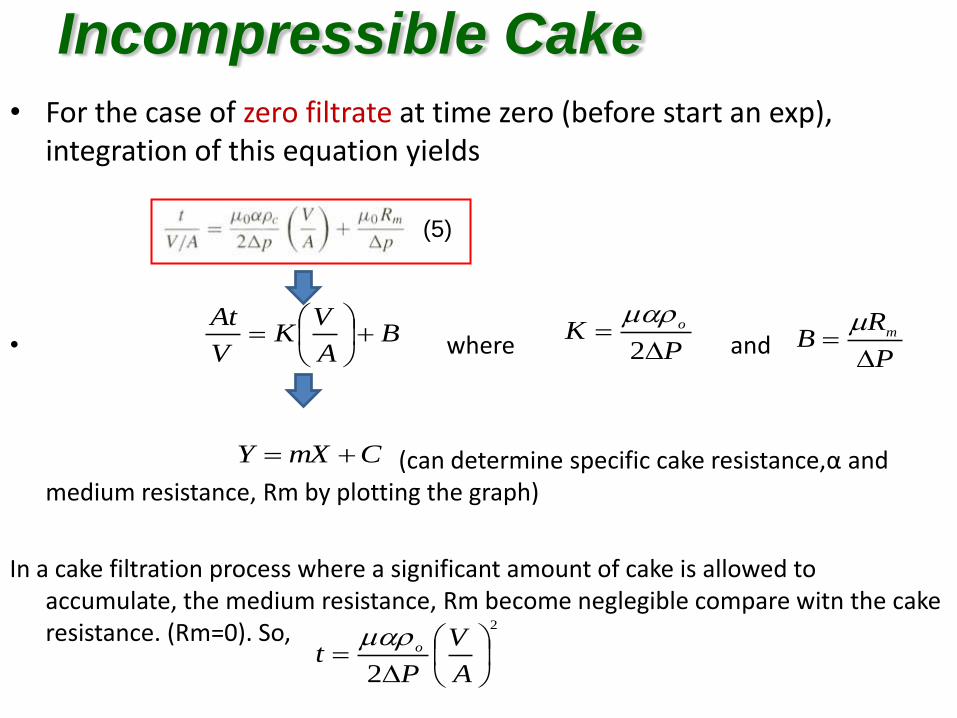
• For the case of zero filtrate at time zero (before start an exp), integration of this equation yields
• where and
(can determine specific cake resistance,α and medium resistance, Rm by plotting the graph)
In a cake filtration process where a significant amount of cake is allowed to accumulate, the medium resistance, Rm become neglegible compare witn the cake resistance. (Rm=0). So,
Incompressible Cake
(5)
BA
VK
V
At
PK o
2
P
RB m
CmXY
2
2
A
V
Pt o
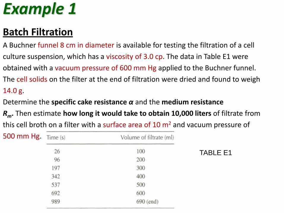
Example 1 Batch Filtration A Buchner funnel 8 cm in diameter is available for testing the filtration of a cell
culture suspension, which has a viscosity of 3.0 cp. The data in Table E1 were
obtained with a vacuum pressure of 600 mm Hg applied to the Buchner funnel.
The cell solids on the filter at the end of filtration were dried and found to weigh
14.0 g.
Determine the specific cake resistance α and the medium resistance
Rm. Then estimate how long it would take to obtain 10,000 liters of filtrate from
this cell broth on a filter with a surface area of 10 m2 and vacuum pressure of
500 mm Hg.
TABLE E1
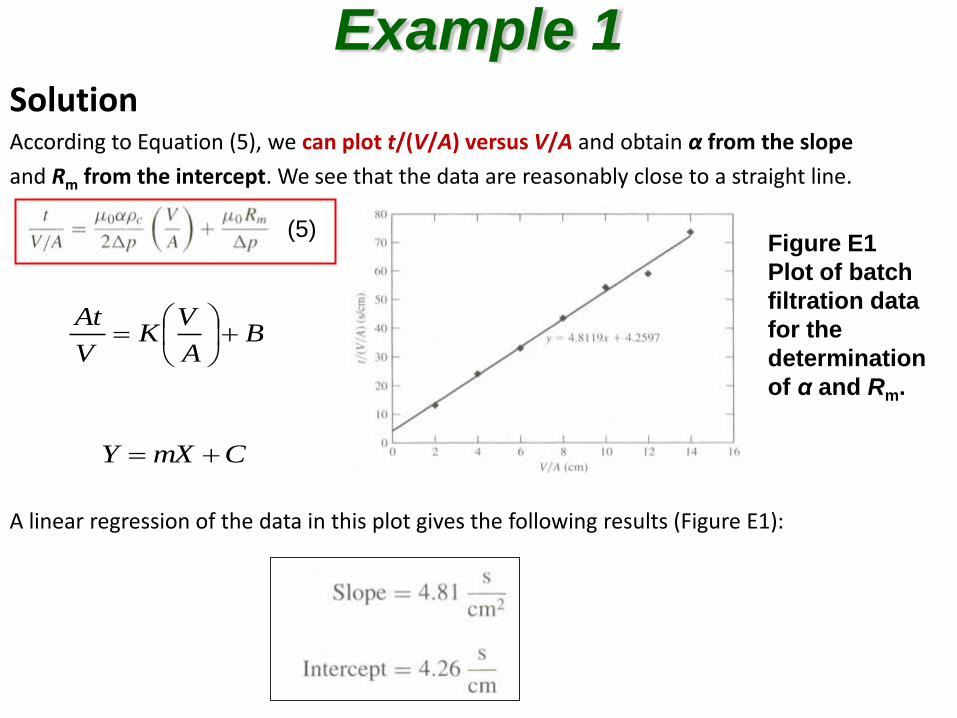
Solution According to Equation (5), we can plot t/(V/A) versus V/A and obtain α from the slope
and Rm from the intercept. We see that the data are reasonably close to a straight line.
A linear regression of the data in this plot gives the following results (Figure E1):
Example 1
Figure E1
Plot of batch
filtration data
for the
determination
of α and Rm.
(5)
BA
VK
V
At
CmXY
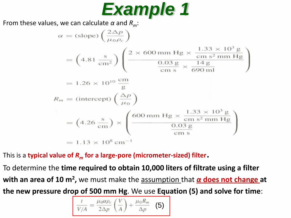
From these values, we can calculate α and Rm:
This is a typical value of Rm for a large-pore (micrometer-sized) filter. To determine the time required to obtain 10,000 liters of filtrate using a filter
with an area of 10 m2, we must make the assumption that α does not change at
the new pressure drop of 500 mm Hg. We use Equation (5) and solve for time:
Example 1
(5)
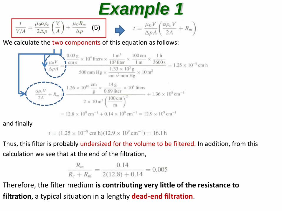
We calculate the two components of this equation as follows:
and finally
Thus, this filter is probably undersized for the volume to be filtered. In addition, from this
calculation we see that at the end of the filtration,
Therefore, the filter medium is contributing very little of the resistance to
filtration, a typical situation in a lengthy dead-end filtration.
Example 1 (5)
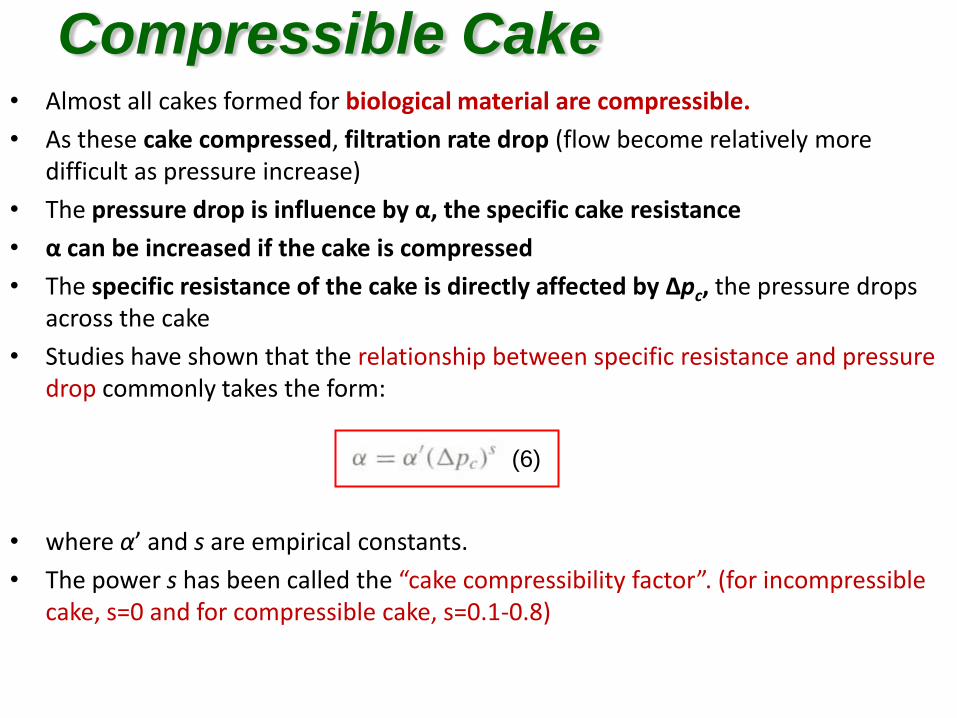
• Almost all cakes formed for biological material are compressible.
• As these cake compressed, filtration rate drop (flow become relatively more difficult as pressure increase)
• The pressure drop is influence by α, the specific cake resistance
• α can be increased if the cake is compressed
• The specific resistance of the cake is directly affected by Δpc, the pressure drops across the cake
• Studies have shown that the relationship between specific resistance and pressure drop commonly takes the form:
• where α’ and s are empirical constants.
• The power s has been called the “cake compressibility factor”. (for incompressible cake, s=0 and for compressible cake, s=0.1-0.8)
Compressible Cake
(6)
Cake Washing
• After filtration, the cake contains a significant amount of solute-rich liquid broth that usually removed by washing the cake
• 2 function of washing:
A) displaces the solute-rich broth trapped in pores in the cake
B) allows diffusion of solute out of the biomass in the cake(enhance recovery if the desired product is in the biomass)
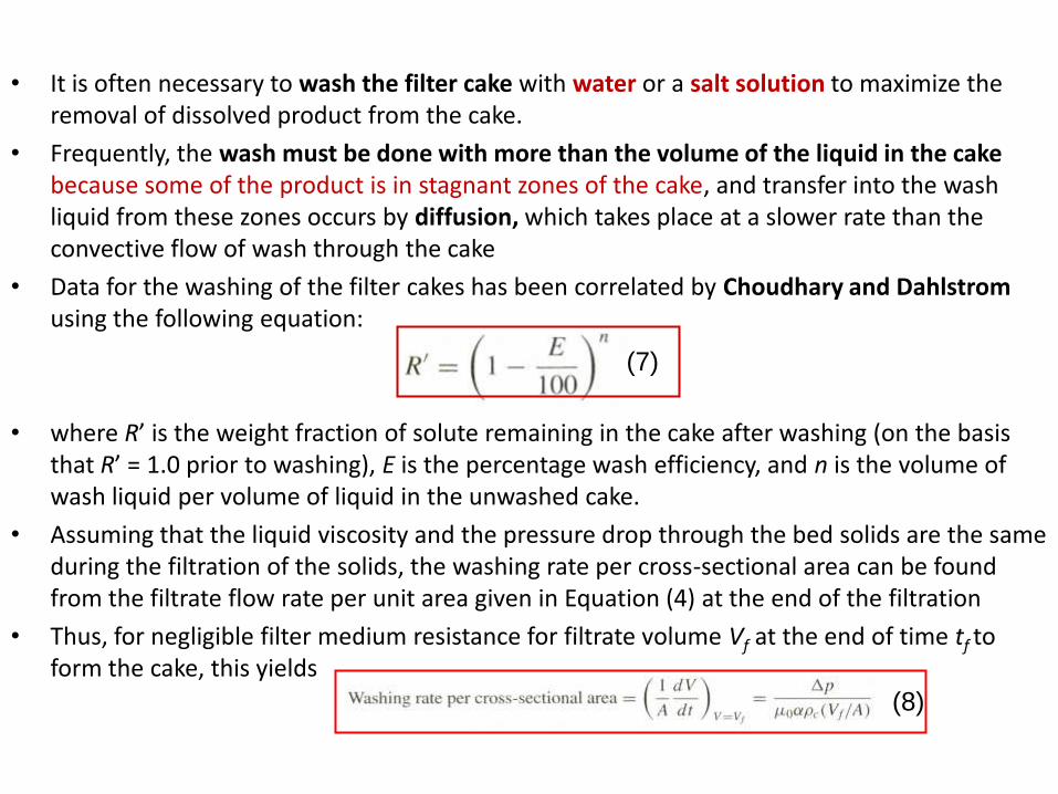
• It is often necessary to wash the filter cake with water or a salt solution to maximize the removal of dissolved product from the cake.
• Frequently, the wash must be done with more than the volume of the liquid in the cake because some of the product is in stagnant zones of the cake, and transfer into the wash liquid from these zones occurs by diffusion, which takes place at a slower rate than the convective flow of wash through the cake
• Data for the washing of the filter cakes has been correlated by Choudhary and Dahlstrom using the following equation:
• where R’ is the weight fraction of solute remaining in the cake after washing (on the basis that R’ = 1.0 prior to washing), E is the percentage wash efficiency, and n is the volume of wash liquid per volume of liquid in the unwashed cake.
• Assuming that the liquid viscosity and the pressure drop through the bed solids are the same during the filtration of the solids, the washing rate per cross-sectional area can be found from the filtrate flow rate per unit area given in Equation (4) at the end of the filtration
• Thus, for negligible filter medium resistance for filtrate volume Vf at the end of time tf to form the cake, this yields
(7)
(8)
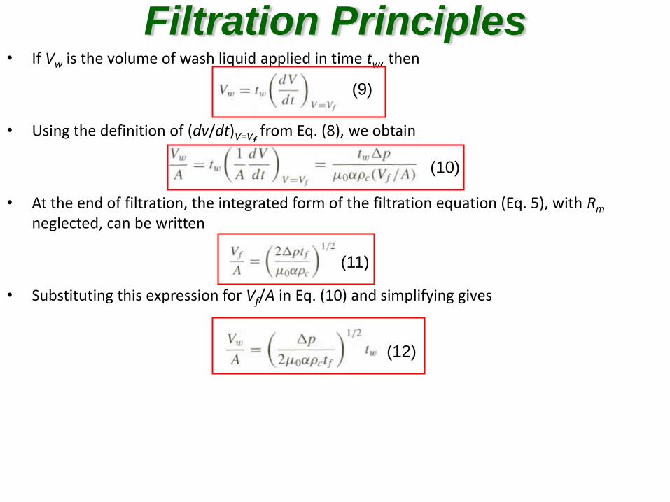
• If Vw is the volume of wash liquid applied in time tw, then
• Using the definition of (dv/dt)V=Vf from Eq. (8), we obtain
• At the end of filtration, the integrated form of the filtration equation (Eq. 5), with Rm neglected, can be written
• Substituting this expression for Vf/A in Eq. (10) and simplifying gives
Filtration Principles
(9)
(10)
(11)
(12)
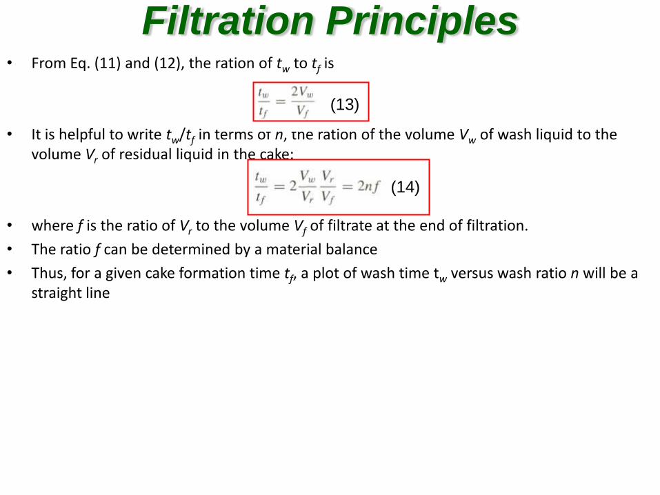
• From Eq. (11) and (12), the ration of tw to tf is
• It is helpful to write tw/tf in terms of n, the ration of the volume Vw of wash liquid to the volume Vr of residual liquid in the cake:
• where f is the ratio of Vr to the volume Vf of filtrate at the end of filtration.
• The ratio f can be determined by a material balance
• Thus, for a given cake formation time tf, a plot of wash time tw versus wash ratio n will be a straight line
Filtration Principles
(13)
(14)
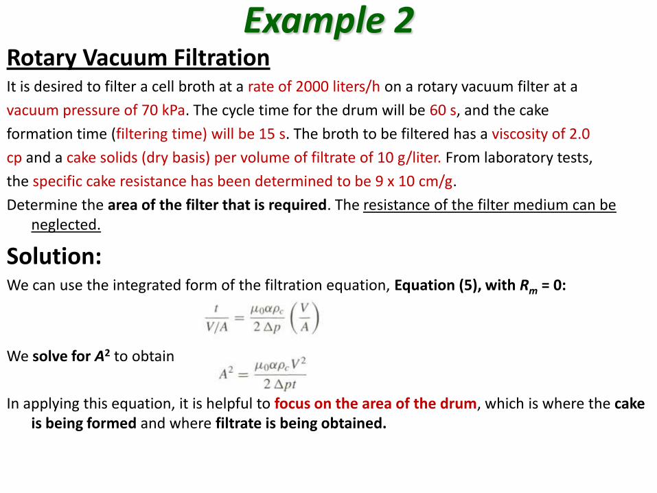
Example 2 Rotary Vacuum Filtration It is desired to filter a cell broth at a rate of 2000 liters/h on a rotary vacuum filter at a
vacuum pressure of 70 kPa. The cycle time for the drum will be 60 s, and the cake
formation time (filtering time) will be 15 s. The broth to be filtered has a viscosity of 2.0
cp and a cake solids (dry basis) per volume of filtrate of 10 g/liter. From laboratory tests,
the specific cake resistance has been determined to be 9 x 10 cm/g.
Determine the area of the filter that is required. The resistance of the filter medium can be neglected.
Solution: We can use the integrated form of the filtration equation, Equation (5), with Rm = 0:
We solve for A2 to obtain
In applying this equation, it is helpful to focus on the area of the drum, which is where the cake is being formed and where filtrate is being obtained.
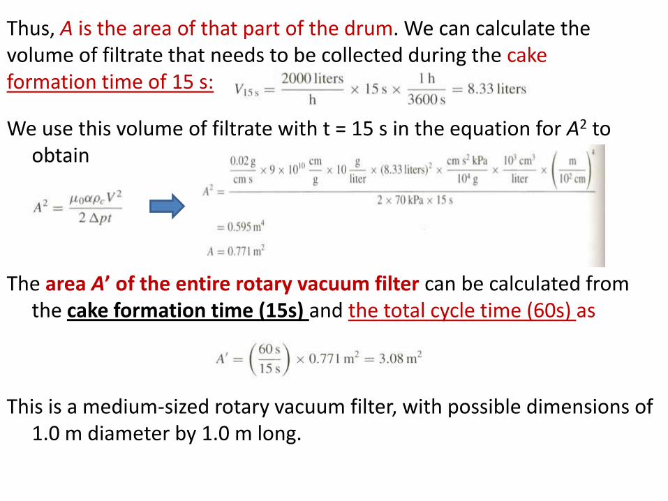
We use this volume of filtrate with t = 15 s in the equation for A2 to obtain
The area A’ of the entire rotary vacuum filter can be calculated from the cake formation time (15s) and the total cycle time (60s) as
This is a medium-sized rotary vacuum filter, with possible dimensions of 1.0 m diameter by 1.0 m long.
Thus, A is the area of that part of the drum. We can calculate the volume of filtrate that needs to be collected during the cake formation time of 15 s:
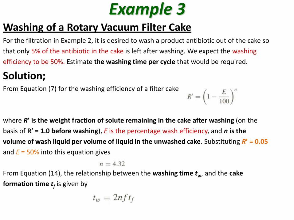
Example 3 Washing of a Rotary Vacuum Filter Cake For the filtration in Example 2, it is desired to wash a product antibiotic out of the cake so
that only 5% of the antibiotic in the cake is left after washing. We expect the washing
efficiency to be 50%. Estimate the washing time per cycle that would be required.
Solution; From Equation (7) for the washing efficiency of a filter cake
where R’ is the weight fraction of solute remaining in the cake after washing (on the
basis of R’ = 1.0 before washing), E is the percentage wash efficiency, and n is the
volume of wash liquid per volume of liquid in the unwashed cake. Substituting R’ = 0.05
and E = 50% into this equation gives
From Equation (14), the relationship between the washing time tw, and the cake
formation time tf is given by
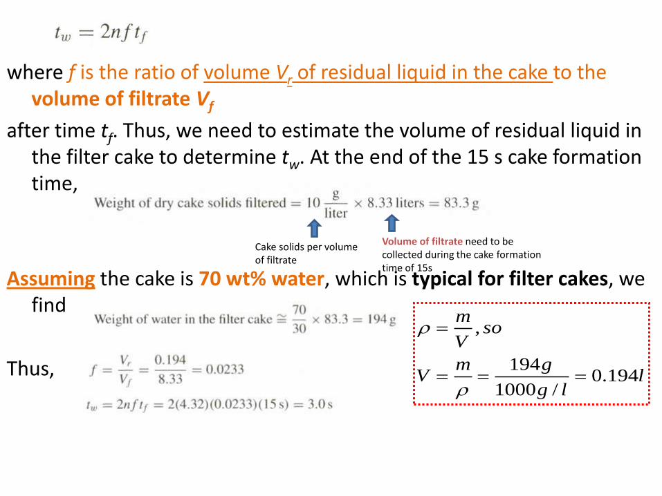
where f is the ratio of volume Vr of residual liquid in the cake to the volume of filtrate Vf
after time tf. Thus, we need to estimate the volume of residual liquid in the filter cake to determine tw. At the end of the 15 s cake formation time,
Assuming the cake is 70 wt% water, which is typical for filter cakes, we find
Thus,
Cake solids per volume of filtrate
Volume of filtrate need to be collected during the cake formation time of 15s
llg
gmV
soV
m
194.0/1000
194
,
Crossflow filtration
as for conventional filtration, scale up of crossflow requires data from laboratory or pilot-scale units
the determination of the size of a plant unit can be done by a direct scaleup of the filtration area based on the feed or output flow rate
continued
for this scaleup, however, it is important that the following variables be kept constant:
inlet and outlet pressures
crossflow (or tangential) velocity
flow channel sizes (height and width)
Feed stream properties – test slurries should be representative of the actual process streams
Membrane type and configuration – test data from one design cannot directly be used to design another geometry
four basic modes of operation of CFF: batch concentration, diafiltration, purification and complete recycle (figure 3.11)
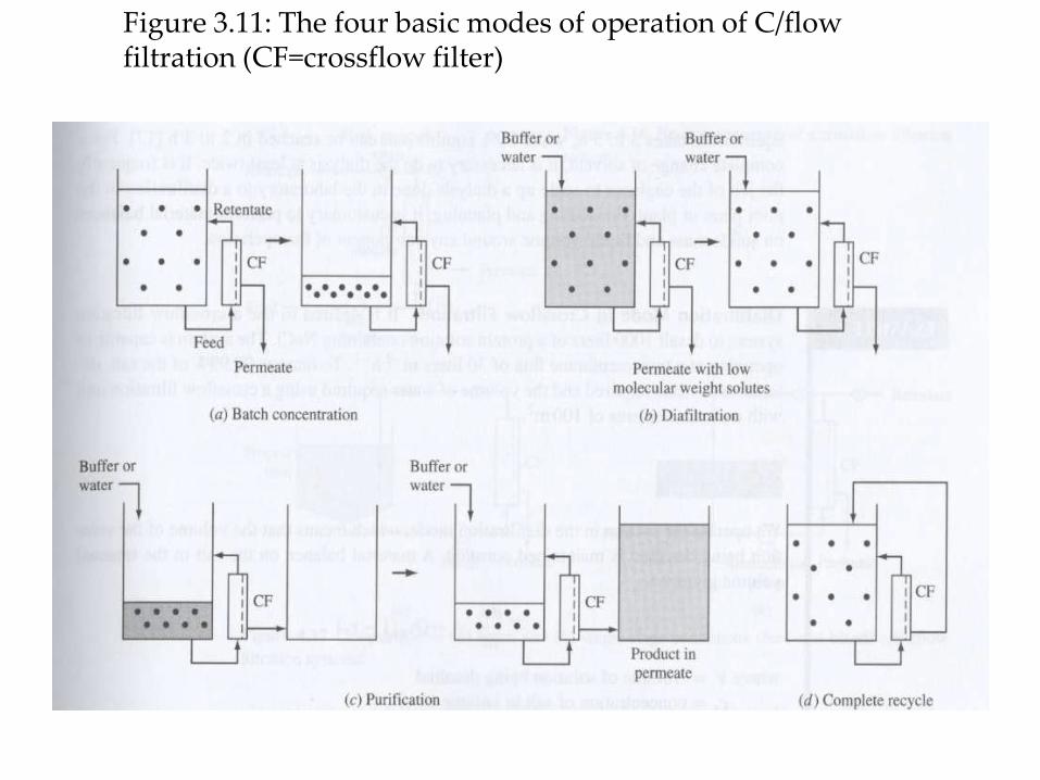
Figure 3.11: The four basic modes of operation of C/flow filtration (CF=crossflow filter)
continued
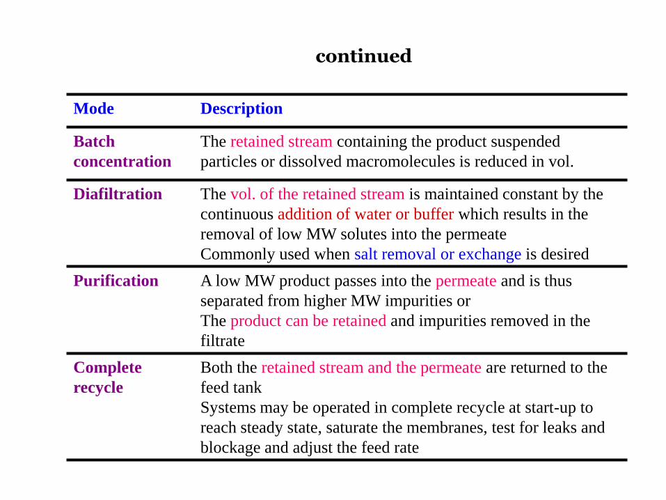
Mode Description
Batch
concentration
The retained stream containing the product suspended
particles or dissolved macromolecules is reduced in vol.
Diafiltration The vol. of the retained stream is maintained constant by the
continuous addition of water or buffer which results in the
removal of low MW solutes into the permeate
Commonly used when salt removal or exchange is desired
Purification A low MW product passes into the permeate and is thus
separated from higher MW impurities or
The product can be retained and impurities removed in the
filtrate
Complete
recycle
Both the retained stream and the permeate are returned to the
feed tank
Systems may be operated in complete recycle at start-up to
reach steady state, saturate the membranes, test for leaks and
blockage and adjust the feed rate
continued
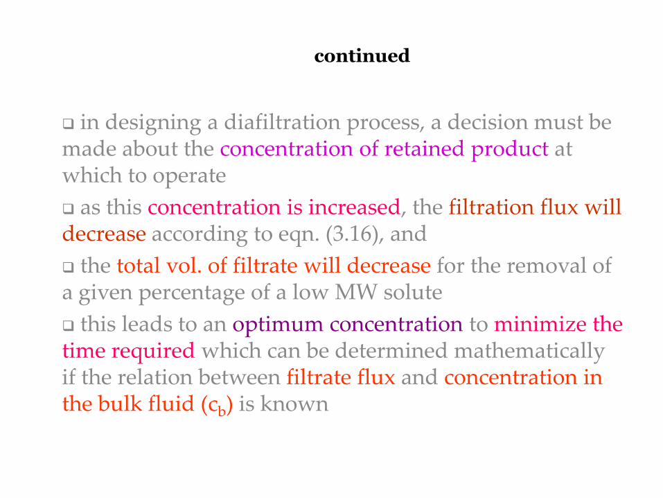
in designing a diafiltration process, a decision must be made about the concentration of retained product at which to operate
as this concentration is increased, the filtration flux will decrease according to eqn. (3.16), and
the total vol. of filtrate will decrease for the removal of a given percentage of a low MW solute
this leads to an optimum concentration to minimize the time required which can be determined mathematically if the relation between filtrate flux and concentration in the bulk fluid (cb) is known
continued
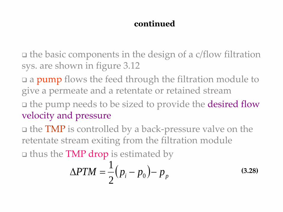
the basic components in the design of a c/flow filtration sys. are shown in figure 3.12
a pump flows the feed through the filtration module to give a permeate and a retentate or retained stream
the pump needs to be sized to provide the desired flow velocity and pressure
the TMP is controlled by a back-pressure valve on the retentate stream exiting from the filtration module
thus the TMP drop is estimated by
pi pppPTM 02
1(3.28)
continued
where pi and po are the retentate pressures in and out of the module respectively and
pp = the pressure of the outlet permeate
in designing a CFF system – important to minimize the occurrence of gas-liquid interfaces, since bioproduct denaturation, especially of proteins, can occur at these interfaces in the presence of mechanical shear and turbulent flow
continued
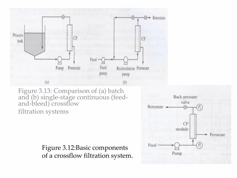
Figure 3.13: Comparison of (a) batch and (b) single-stage continuous (feed-and-bleed) crossflow filtration systems
Figure 3.12:Basic components of a crossflow filtration system.
continued
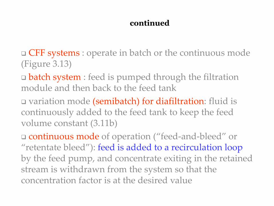
CFF systems : operate in batch or the continuous mode (Figure 3.13)
batch system : feed is pumped through the filtration module and then back to the feed tank
variation mode (semibatch) for diafiltration: fluid is continuously added to the feed tank to keep the feed volume constant (3.11b)
continuous mode of operation (“feed-and-bleed” or “retentate bleed”): feed is added to a recirculation loop by the feed pump, and concentrate exiting in the retained stream is withdrawn from the system so that the concentration factor is at the desired value
continued
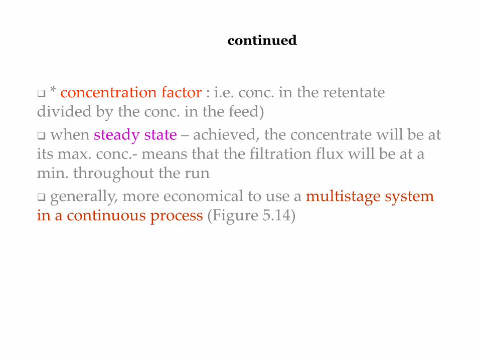
* concentration factor : i.e. conc. in the retentate divided by the conc. in the feed)
when steady state – achieved, the concentrate will be at its max. conc.- means that the filtration flux will be at a min. throughout the run
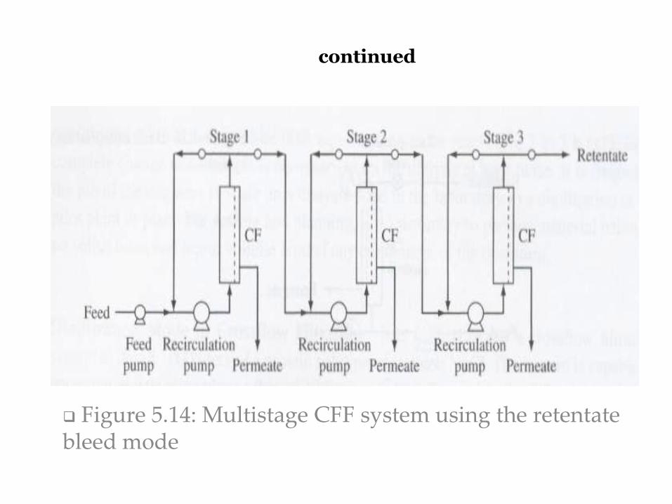
generally, more economical to use a multistage system in a continuous process (Figure 5.14)
continued
Figure 5.14: Multistage CFF system using the retentate bleed mode
continued
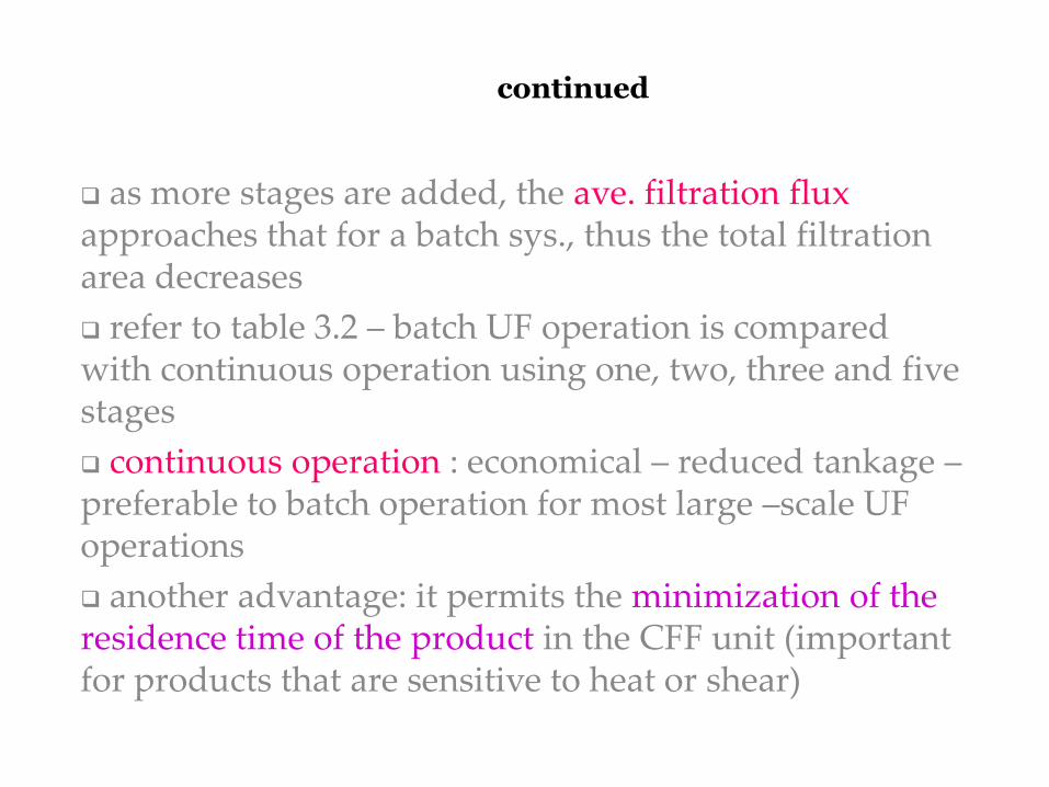
as more stages are added, the ave. filtration flux approaches that for a batch sys., thus the total filtration area decreases
refer to table 3.2 – batch UF operation is compared with continuous operation using one, two, three and five stages
continuous operation : economical – reduced tankage – preferable to batch operation for most large –scale UF operations
another advantage: it permits the minimization of the residence time of the product in the CFF unit (important for products that are sensitive to heat or shear)
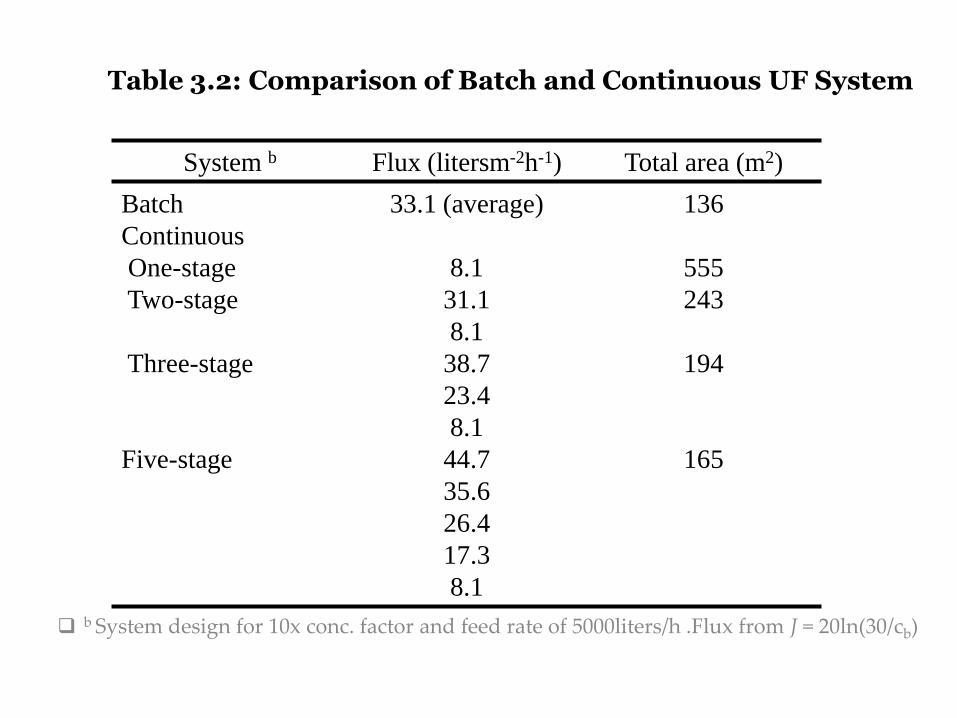
Table 3.2: Comparison of Batch and Continuous UF System
b System design for 10x conc. factor and feed rate of 5000liters/h .Flux from J = 20ln(30/cb)
System b Flux (litersm-2h-1) Total area (m2)
Batch
Continuous
One-stage
Two-stage
Three-stage
Five-stage
33.1 (average)
8.1
31.1
8.1
38.7
23.4
8.1
44.7
35.6
26.4
17.3
8.1
136
555
243
194
165
Biotechnological products produced by different
types of cells can be intracellular or extracellular.
If these are intracellular (inside the cell), the cells
have to be disrupted to release these products
before further separation can take place.
Cell disruption / lysis is a method or process for
releasing biological molecules from inside a cell
(breaking / lysing cells and tissues)
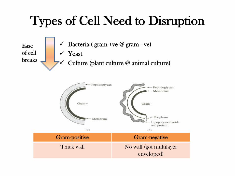
Types of Cell Need to Disruption
Bacteria ( gram +ve @ gram –ve)
Yeast
Culture (plant culture @ animal culture)
Ease
of cell
breaks
Gram-positive Gram-negative
Thick wall No wall (got multilayer
enveloped)
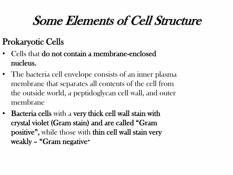
Some Elements of Cell Structure
Prokaryotic Cells
• Cells that do not contain a membrane-enclosed
nucleus.
• The bacteria cell envelope consists of an inner plasma
membrane that separates all contents of the cell from
the outside world, a peptidoglycan cell wall, and outer
membrane
• Bacteria cells with a very thick cell wall stain with
crystal violet (Gram stain) and are called “Gram
positive”, while those with thin cell wall stain very
weakly – “Gram negative”
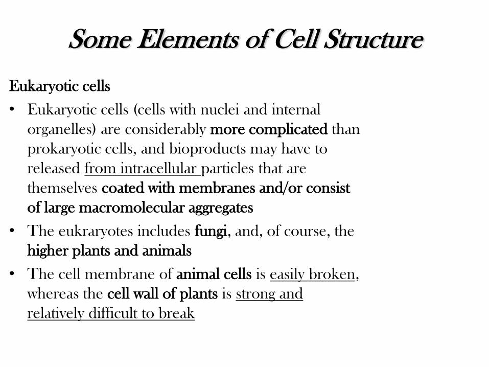
Eukaryotic cells
• Eukaryotic cells (cells with nuclei and internal
organelles) are considerably more complicated than
prokaryotic cells, and bioproducts may have to
released from intracellular particles that are
themselves coated with membranes and/or consist
of large macromolecular aggregates
• The eukraryotes includes fungi, and, of course, the
higher plants and animals
• The cell membrane of animal cells is easily broken,
whereas the cell wall of plants is strong and
relatively difficult to break
Some Elements of Cell Structure
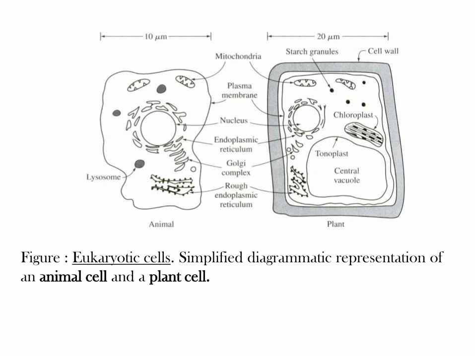
Figure : Eukaryotic cells. Simplified diagrammatic representation of
an animal cell and a plant cell.
Different cell disruption techniques are used. These
include:
Physical methods
•Disruption in ball mill or pebble mill
•Disruption using a colloid mill
•Disruption using French press
•Disruption using ultrasonic vibrations
Chemical methods
•Disruption using detergents
•Disruption using enzymes e.g. lysozyme
•Combination of detergent and enzyme
•Disruption using solvents
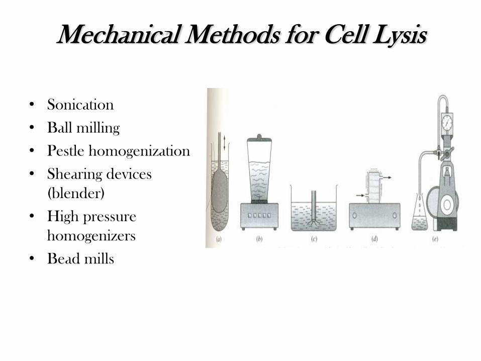
Mechanical Methods for Cell Lysis
• Sonication
• Ball milling
• Pestle homogenization
• Shearing devices
(blender)
• High pressure
homogenizers
• Bead mills
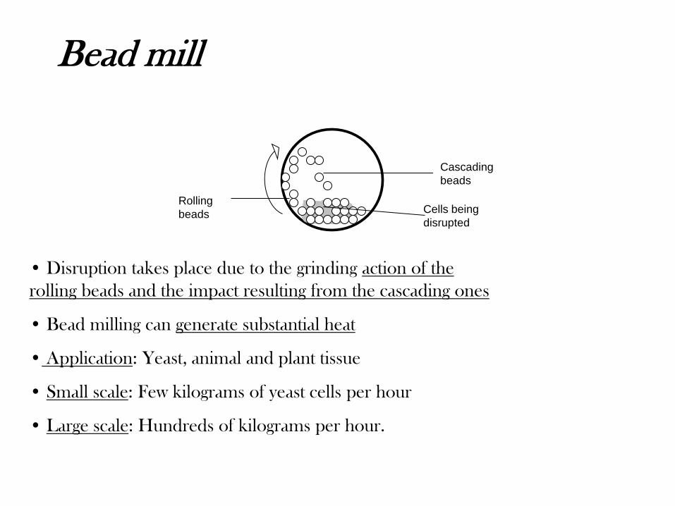
Bead mill
Cascading
beads
Cells being
disrupted
Rolling
beads
• Disruption takes place due to the grinding action of the
rolling beads and the impact resulting from the cascading ones
• Bead milling can generate substantial heat
• Application: Yeast, animal and plant tissue
• Small scale: Few kilograms of yeast cells per hour
• Large scale: Hundreds of kilograms per hour.
ERT 313/4 BIOSEPARATION ENGINEERING
SEM 2 (2010/2011)
ERT 313/4 BIOSEPARATION ENGINEERING
SEM 2 (2010/2011)
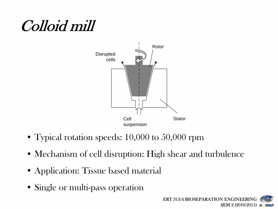
Colloid mill
Cell
suspension
Rotor
Stator
Disrupted
cells
• Typical rotation speeds: 10,000 to 50,000 rpm
• Mechanism of cell disruption: High shear and turbulence
• Application: Tissue based material
• Single or multi-pass operation
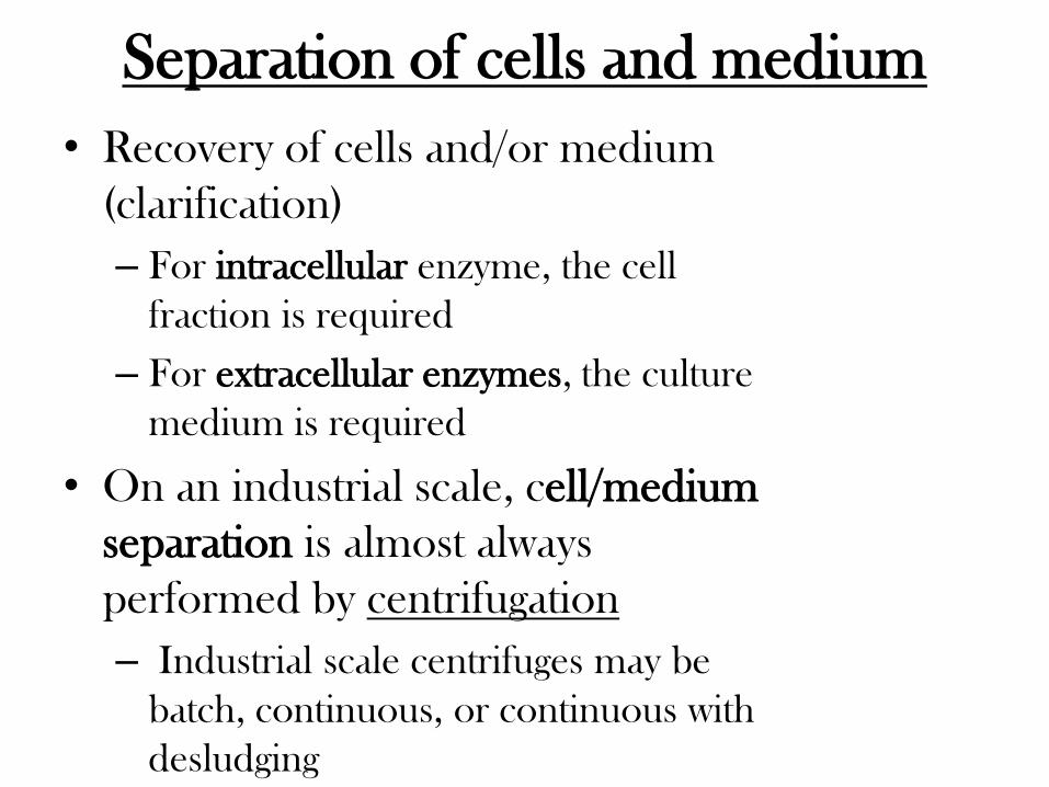
Separation of cells and medium
• Recovery of cells and/or medium
(clarification)
– For intracellular enzyme, the cell
fraction is required
– For extracellular enzymes, the culture
medium is required
• On an industrial scale, cell/medium
separation is almost always
performed by centrifugation
– Industrial scale centrifuges may be
batch, continuous, or continuous with
desludging

CENTRIF UGATION
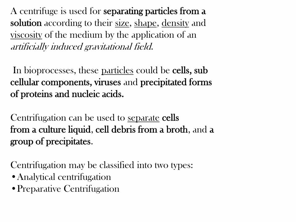
A centrifuge is used for separating particles from a
solution according to their size, shape, density and
viscosity of the medium by the application of an
artificially induced gravitational field.
In bioprocesses, these particles could be cells, sub
cellular components, viruses and precipitated forms
of proteins and nucleic acids.
Centrifugation can be used to separate cells
from a culture liquid, cell debris from a broth, and a
group of precipitates.
Centrifugation may be classified into two types:
•Analytical centrifugation
•Preparative Centrifugation

Tubular Bowl Centrifuge
• Most useful for solid-liquid separation with enzymatic isolation
• Can achieve excellent separation of microbial cells and animal, plant, and most microbial cell debris in solution
Disc Bowl Centrifuge
• Widely used for removing cells and animal debris
• Can partially recover microbial cell debris and protein precipitates
Industrial centrifuges
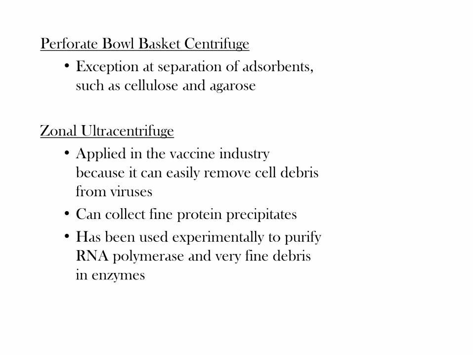
Perforate Bowl Basket Centrifuge
• Exception at separation of adsorbents,
such as cellulose and agarose
Zonal Ultracentrifuge
• Applied in the vaccine industry
because it can easily remove cell debris
from viruses
• Can collect fine protein precipitates
• Has been used experimentally to purify
RNA polymerase and very fine debris
in enzymes
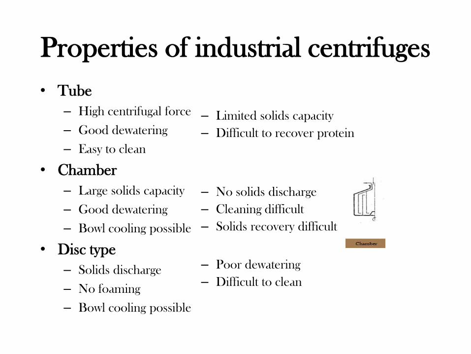
Properties of industrial centrifuges
• Tube
– High centrifugal force
– Good dewatering
– Easy to clean
• Chamber
– Large solids capacity
– Good dewatering
– Bowl cooling possible
• Disc type
– Solids discharge
– No foaming
– Bowl cooling possible
– Limited solids capacity
– Difficult to recover protein
– No solids discharge
– Cleaning difficult
– Solids recovery difficult
– Poor dewatering
– Difficult to clean
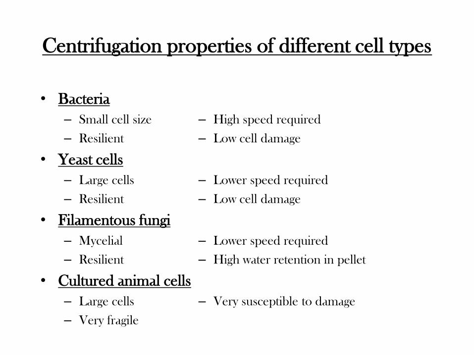
Centrifugation properties of different cell types
• Bacteria
– Small cell size
– Resilient
• Yeast cells
– Large cells
– Resilient
• Filamentous fungi
– Mycelial
– Resilient
• Cultured animal cells
– Large cells
– Very fragile
– High speed required
– Low cell damage
– Lower speed required
– Low cell damage
– Lower speed required
– High water retention in pellet
– Very susceptible to damage
Forced Developed in Centrifugal Separation
1. Introductions
• Centrifugal separators use the common principal
that an object whirled about an axis or center
point a constant radial distance from the point is
acted on by a force
• The object is constantly changing direction and is
thus accelerating, even though the rotational
speed is constant
• This centripetal force acts in a direction toward
the center of rotation
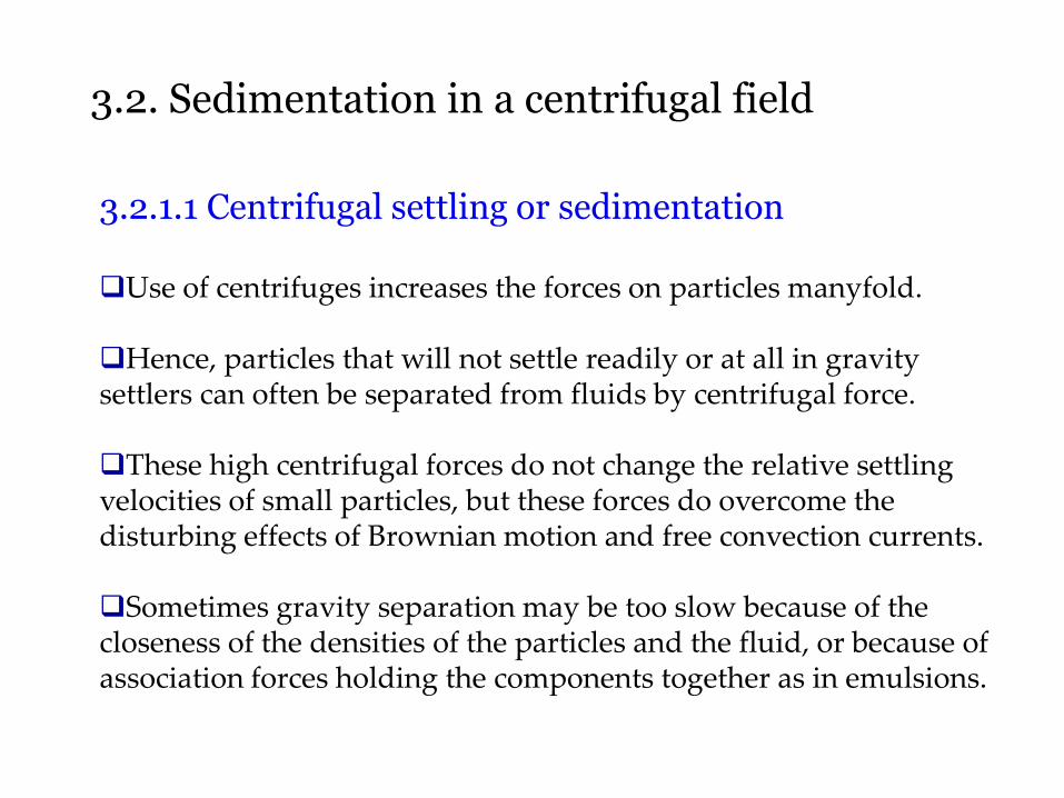
3.2. Sedimentation in a centrifugal field
3.2.1.1 Centrifugal settling or sedimentation Use of centrifuges increases the forces on particles manyfold. Hence, particles that will not settle readily or at all in gravity settlers can often be separated from fluids by centrifugal force. These high centrifugal forces do not change the relative settling velocities of small particles, but these forces do overcome the disturbing effects of Brownian motion and free convection currents. Sometimes gravity separation may be too slow because of the closeness of the densities of the particles and the fluid, or because of association forces holding the components together as in emulsions.
continued
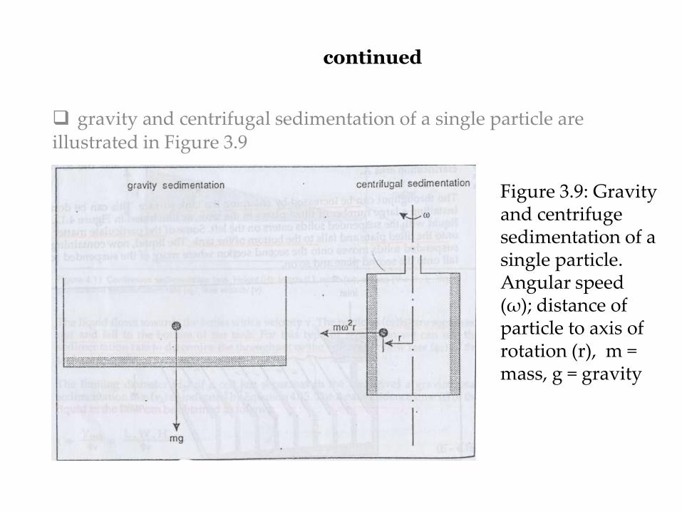
gravity and centrifugal sedimentation of a single particle are illustrated in Figure 3.9
Figure 3.9: Gravity and centrifuge sedimentation of a single particle. Angular speed (ω); distance of particle to axis of rotation (r), m = mass, g = gravity
continued
An example in the dairy industry is the separation of cream from whole milk, giving skim milk.
Gravity separation takes hours, while centrifugal separation is accomplished in minutes in a cream separator.
Centrifugal settling or separation is employed in many food industries, such as breweries, vegetable-oil processing, fish-protein-concentrate processing, fruit juice processing to remove cellular materials, and so on.
Centrifugal separation is also used in drying crystals and for separating emulsions into their constituent liquids or solid—liquid
continued
3.2.1.2 Centrifugal filtration Centrifuges are also used in centrifugal filtration, where a centrifugal force is used instead of a pressure difference to cause the flow of slurry in a filter where a cake of solids builds up on a screen. The cake of granular solids from the slurry is deposited on a filter medium held in a rotating basket, washed, and then spun ‘dry.’ Centrifuges and ordinary filters are competitive in most solid—liquid separation problems.
If the object being rotated is a cylindrical container, the contents of fluid and solids exert an equal and opposite force, called centrifugal force, outward to the walls of the container. This is the force that causes settling or sedimentation of particles through a layer of liquid or filtration of a liquid through a bed of filter cake held inside a perforated rotating chamber In Fig. 3.10a cylindrical bowl is shown rotating, with a slurry feed of solid particles and liquid being admitted at the center
3.2.2 Forces developed in centrifugal separation
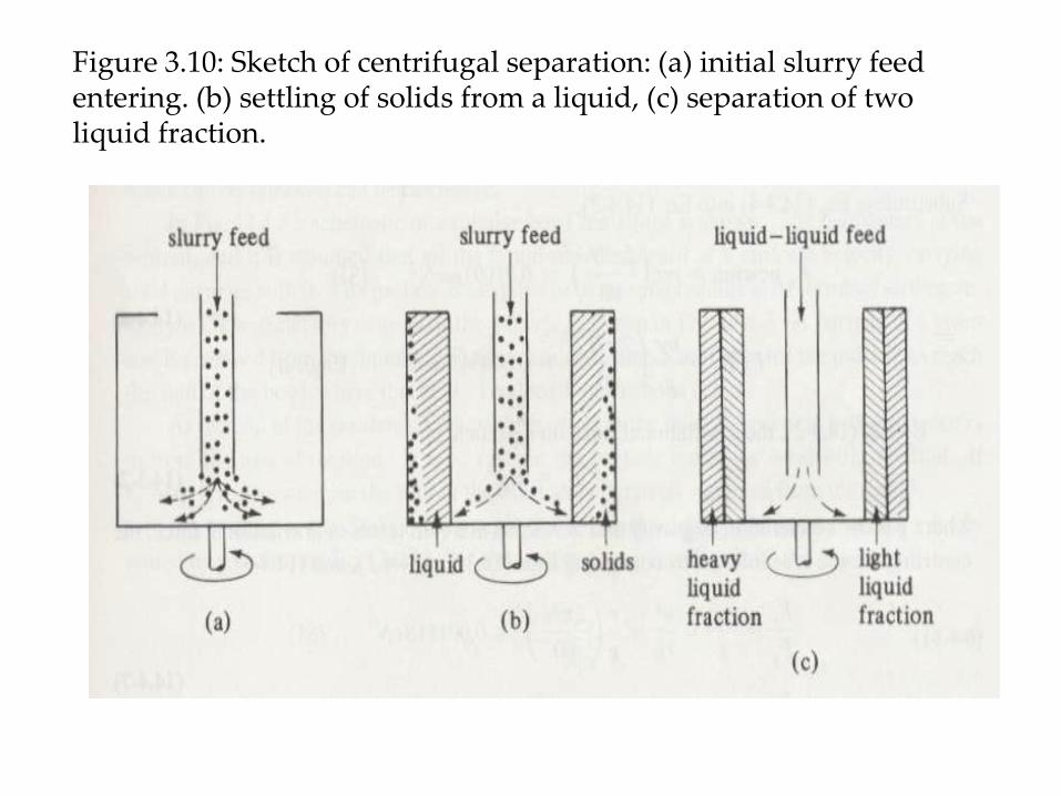
Figure 3.10: Sketch of centrifugal separation: (a) initial slurry feed entering. (b) settling of solids from a liquid, (c) separation of two liquid fraction.
continued
The feed enters and is immediately thrown outward to the walls of the container, as in Fig. 3.10b. The liquid and solids are now acted upon by the vertical gravitational force and the horizontal centrifugal force. The centrifugal force is usually so large that the force of gravity may he neglected. The liquid layer then assumes the equilibrium position, with the surface almost vertical. The particles settle horizontally out ward and press against the vertical bowl wall. in Fig. 3.10c two liquids having different densities are being separated by the centrifuge. The denser fluid will occupy the outer periphery since the centrifugal force on it is greater.
3.2.2.1 Equations for centrifugal force
In Fig 3.11 a schematic of a tubular-bowl centrifuge is shown. The feed enters at the bottom, and it is assumed that all the liquid moves upward at a uniform velocity carrying solid particles with it. The particle is assumed to be moving radially at its terminal settling velocity υt. The trajectory or path of the particle is shown in Fig. 3.10. A particle of a given size is removed from the liquid if sufficient residence time is available for the particle to reach the wall of the bowl where it is held. The length of the bowl is b m. At the end of the residence time of the particle in the fluid, the particle is at a distance rB m from the axis of rotation. If rB < r2, then the particle leaves the bowl with the fluid.
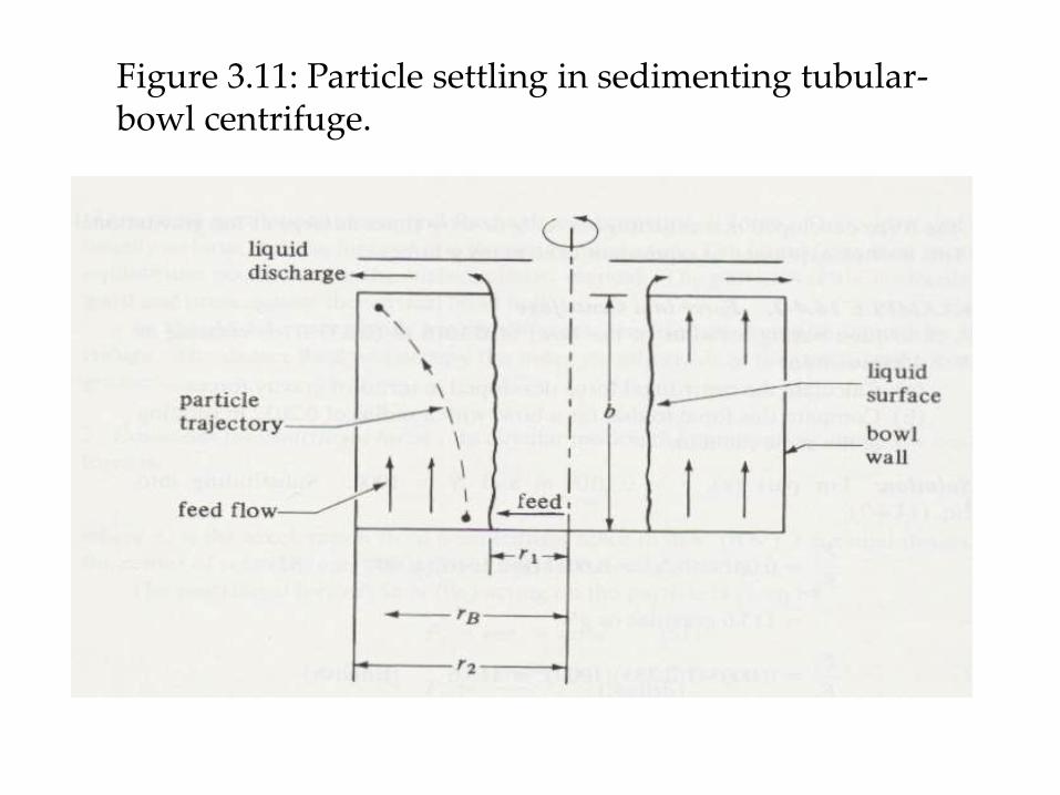
Figure 3.11: Particle settling in sedimenting tubular-bowl centrifuge.
continued
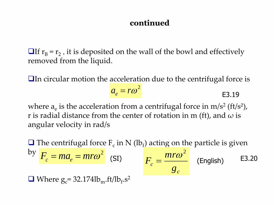
If rB = r2 , it is deposited on the wall of the bowl and effectively removed from the liquid.
In circular motion the acceleration due to the centrifugal force is where ae is the acceleration from a centrifugal force in m/s2 (ft/s2), r is radial distance from the center of rotation in m (ft), and ω is angular velocity in rad/s The centrifugal force Fc in N (lbf) acting on the particle is given by
Where gc= 32.174lbm.ft/lbf.s
2
2rae E3.19
2mrmaF ec
c
cg
mrF
2 E3.20 (SI) (English)
continued
r
m
rmrFc
22
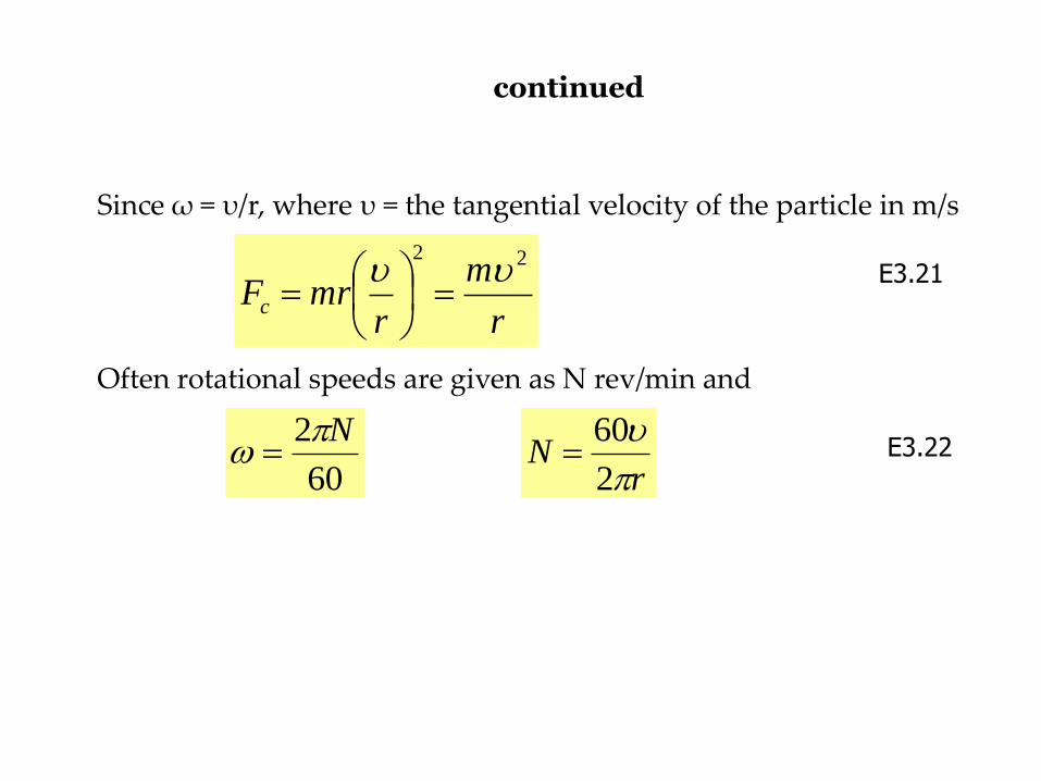
Since ω = υ/r, where υ = the tangential velocity of the particle in m/s Often rotational speeds are given as N rev/min and
E3.21
60
2 N
rN
2
60 E3.22
continued
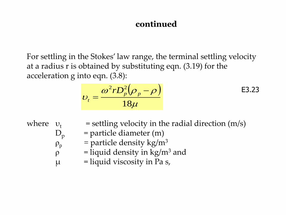
For settling in the Stokes’ law range, the terminal settling velocity at a radius r is obtained by substituting eqn. (3.19) for the acceleration g into eqn. (3.8): where υt = settling velocity in the radial direction (m/s) Dp = particle diameter (m) ρp = particle density kg/m3 ρ = liquid density in kg/m3 and μ = liquid viscosity in Pa s,
18
22
pp
t
rD E3.23
continued
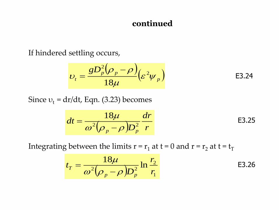
If hindered settling occurs, Since υt = dr/dt, Eqn. (3.23) becomes Integrating between the limits r = r1 at t = 0 and r = r2 at t = tT
p
pp
t
gD
2
2
18
E3.24
r
dr
Ddt
pp
22
18
1
2
22ln
18
r
r
Dt
pp
T
E3.25
E3.26
continued
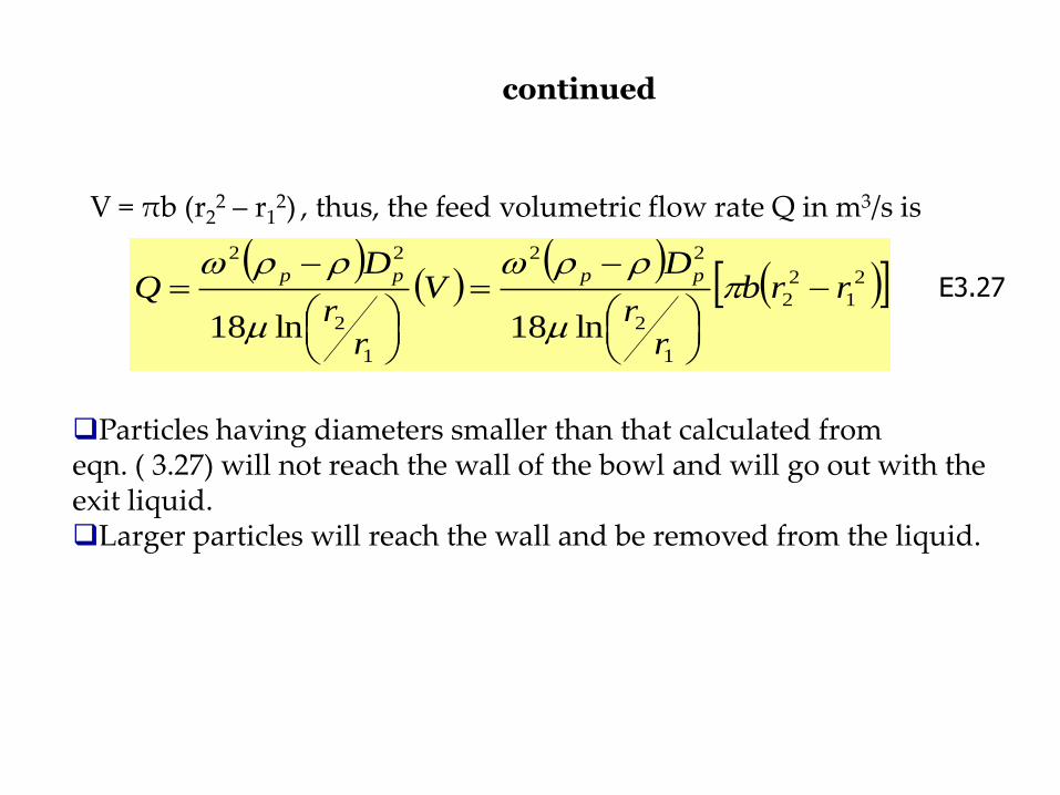
V = πb (r22 – r1
2) , thus, the feed volumetric flow rate Q in m3/s is
2
1
2
2
1
2
22
1
2
22
ln18ln18
rrb
rr
DV
rr
DQ
pppp
E3.27
Particles having diameters smaller than that calculated from eqn. ( 3.27) will not reach the wall of the bowl and will go out with the exit liquid. Larger particles will reach the wall and be removed from the liquid.
Notes:
centrifugation is most effective when the particles to be separated are large, the liquid viscosity is low and the density difference between particles and fluid is great
it is also assisted by large centrifuge radius and high rotational speed
in centrifugation of biological solids such as cells, the particles are very small, the viscosity of the medium can be relatively high and the particle density is very similar to the suspending fluid. These disadvantages – easily overcome in the lab with small centrifuges operated at high speed
continued
however, problems arise in industrial centrifugation
when large quantities of material must be treated
centrifuge capacity cannot be increased by simply increasing the size of equipment without limit; mechanical stress in centrifuges increases in proportion to (radius)2 so that safe operating speeds are substantially lower in large equipment
the need for continuous throughput of material in industrial applications also restricts practical operating speeds
to overcome these difficulties, a range of centrifuges has been developed for bioprocessing industry
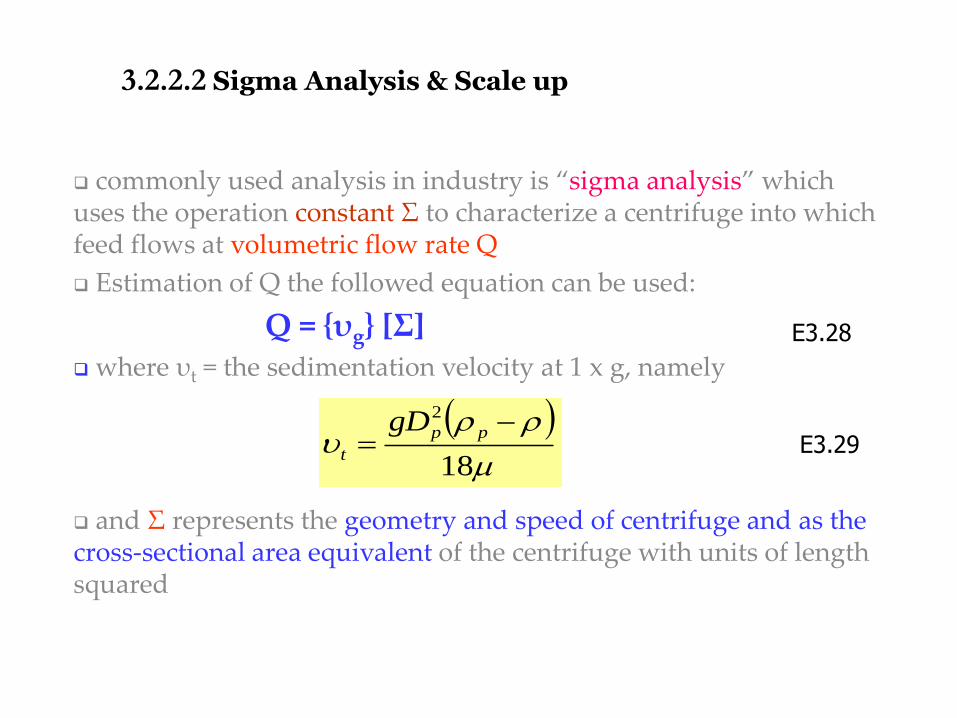
3.2.2.2 Sigma Analysis & Scale up
commonly used analysis in industry is “sigma analysis” which uses the operation constant Σ to characterize a centrifuge into which feed flows at volumetric flow rate Q
Estimation of Q the followed equation can be used:
Q = {υg} [Σ] where υt = the sedimentation velocity at 1 x g, namely
and Σ represents the geometry and speed of centrifuge and as the cross-sectional area equivalent of the centrifuge with units of length squared
E3.28
E3.29
18
2
pp
t
gD
continued
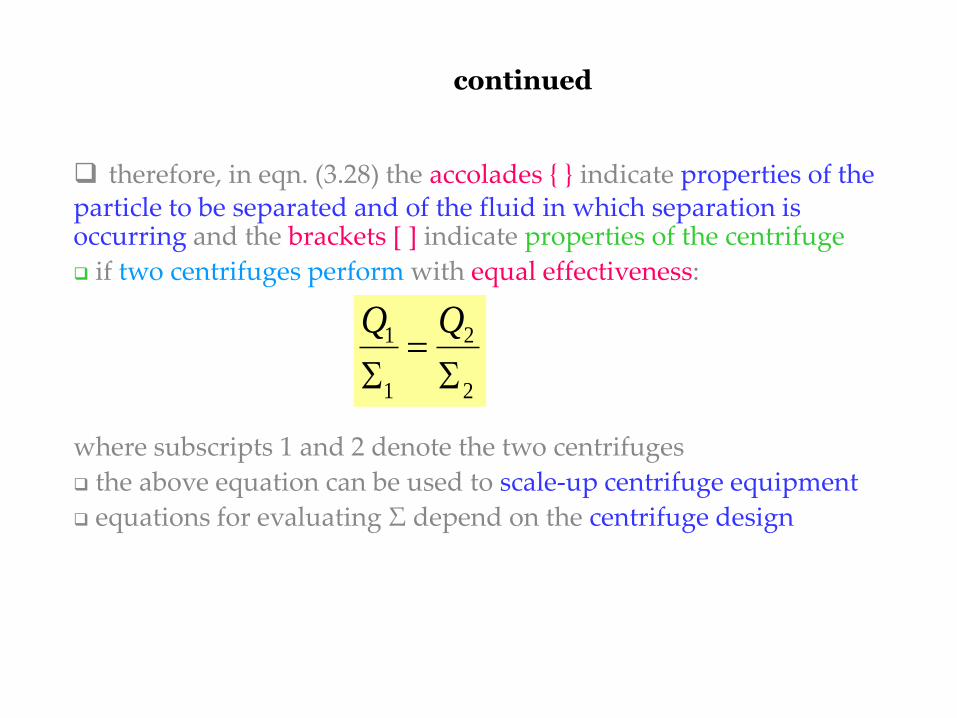
therefore, in eqn. (3.28) the accolades { } indicate properties of the particle to be separated and of the fluid in which separation is occurring and the brackets [ ] indicate properties of the centrifuge
if two centrifuges perform with equal effectiveness:
where subscripts 1 and 2 denote the two centrifuges
the above equation can be used to scale-up centrifuge equipment
equations for evaluating Σ depend on the centrifuge design
2
2
1
1
continued
the above equations for Σ are based on ideal operating conditions
Because different types of centrifuge deviate to varying degrees from ideal operation that equation cannot generally be used to compare different centrifuge configurations
performance of any centrifuge can deviate from theoretical production due to factors such as
Particle shape and size distribution
Aggregation of particles
Non-uniform flow distribution in the centrifuge and
Interaction between particles during sedimentation
Experimental tests must be performed to account for these factors
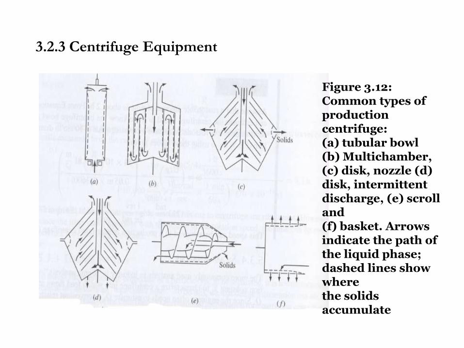
Figure 3.12: Common types of production centrifuge: (a) tubular bowl (b) Multichamber, (c) disk, nozzle (d) disk, intermittent discharge, (e) scroll and (f) basket. Arrows indicate the path of the liquid phase; dashed lines show where the solids accumulate
3.2.3 Centrifuge Equipment
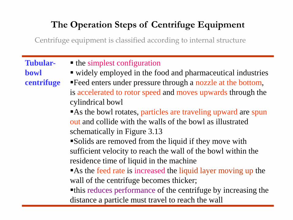
The Operation Steps of Centrifuge Equipment
Tubular-
bowl
centrifuge
the simplest configuration
widely employed in the food and pharmaceutical industries
Feed enters under pressure through a nozzle at the bottom,
is accelerated to rotor speed and moves upwards through the
cylindrical bowl
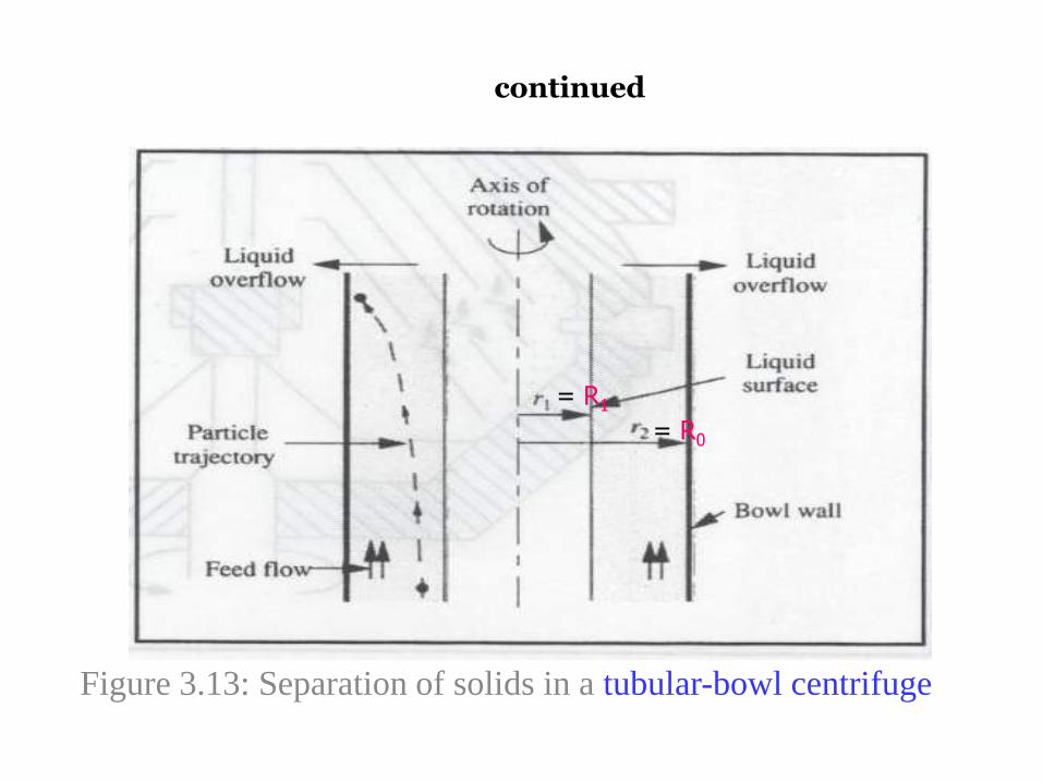
As the bowl rotates, particles are traveling upward are spun
out and collide with the walls of the bowl as illustrated
schematically in Figure 3.13
Solids are removed from the liquid if they move with
sufficient velocity to reach the wall of the bowl within the
residence time of liquid in the machine
As the feed rate is increased the liquid layer moving up the
wall of the centrifuge becomes thicker;
this reduces performance of the centrifuge by increasing the
distance a particle must travel to reach the wall
Centrifuge equipment is classified according to internal structure
continued
Figure 3.13: Separation of solids in a tubular-bowl centrifuge
= R1
= R0
continued
liquid from the feed spills over a weir at the top of the bowl;
solids which have collided with the walls are collected
separately
when the thickness of sediment collecting in the bowl reaches
the position of the liquid-overflow weir, separation efficiency
declines rapidly.This limits the capacity of the centrifuge
applied mainly for difficult separations requiring high
centrifugal forces
solids in tubular centrifuges are accelerated by forces between
13 000 and 16 000 times the force of gravity
continued
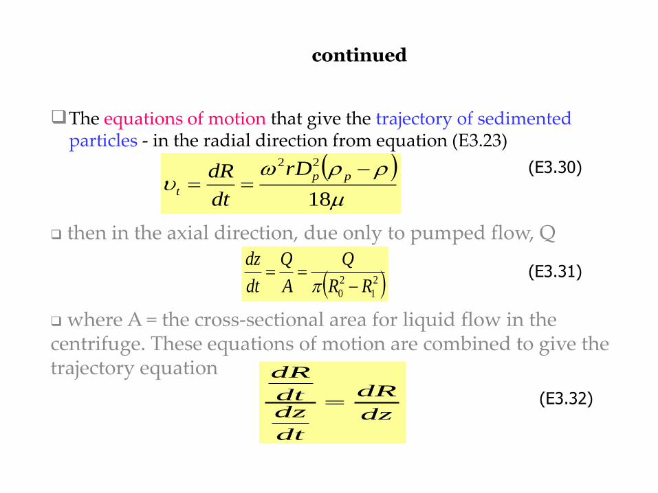
then in the axial direction, due only to pumped flow, Q
where A = the cross-sectional area for liquid flow in the centrifuge. These equations of motion are combined to give the trajectory equation
2
1
2
0 RR
Q
A
Q
dt
dz
(E3.30)
dz
dR
dt
dzdt
dR
(E3.31)
The equations of motion that give the trajectory of sedimented particles - in the radial direction from equation (E3.23)
18
22
pp
t
rD
dt
dR
(E3.32)
continued
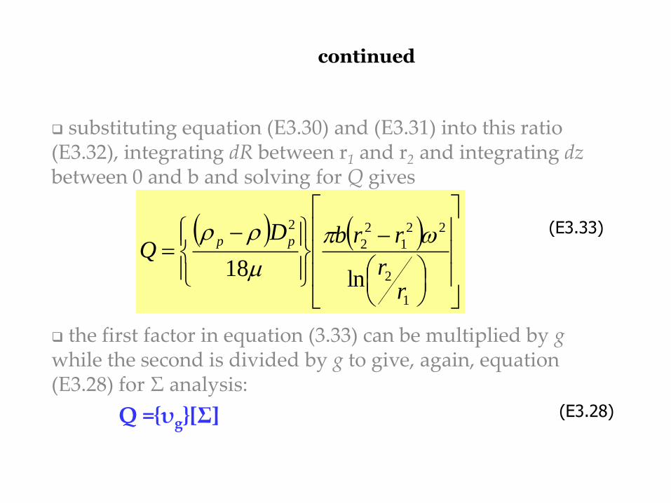
substituting equation (E3.30) and (E3.31) into this ratio (E3.32), integrating dR between r1 and r2 and integrating dz between 0 and b and solving for Q gives
the first factor in equation (3.33) can be multiplied by g while the second is divided by g to give, again, equation (E3.28) for Σ analysis:
Q ={υg}[Σ]
(E3.33)
(E3.28)
1
2
22
1
2
2
2
ln18r
r
rrbDQ
pp
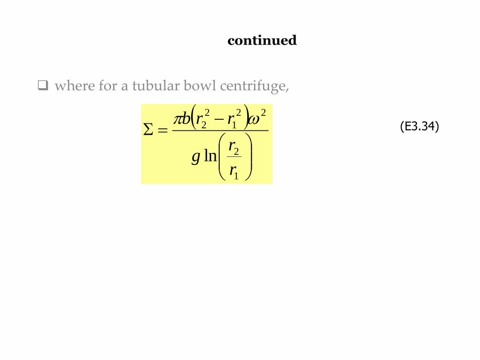
continued
where for a tubular bowl centrifuge,
1
2
22
1
2
2
lnr
rg
rrb (E3.34)
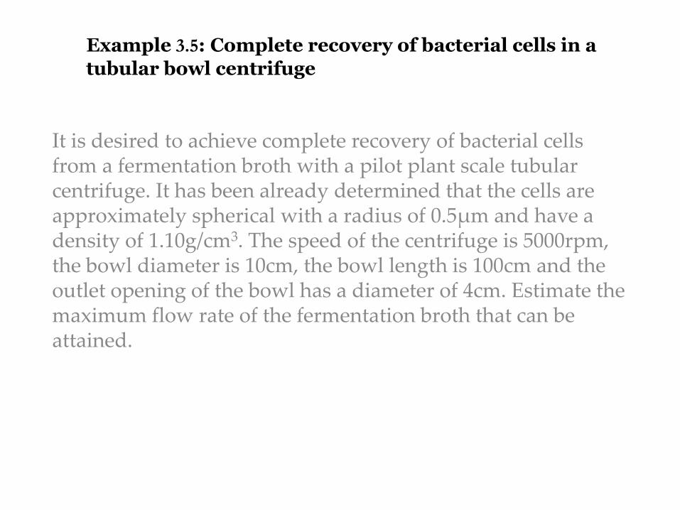
Example 3.5: Complete recovery of bacterial cells in a
tubular bowl centrifuge
It is desired to achieve complete recovery of bacterial cells from a fermentation broth with a pilot plant scale tubular centrifuge. It has been already determined that the cells are approximately spherical with a radius of 0.5μm and have a density of 1.10g/cm3. The speed of the centrifuge is 5000rpm, the bowl diameter is 10cm, the bowl length is 100cm and the outlet opening of the bowl has a diameter of 4cm. Estimate the maximum flow rate of the fermentation broth that can be attained.

Solution
continued
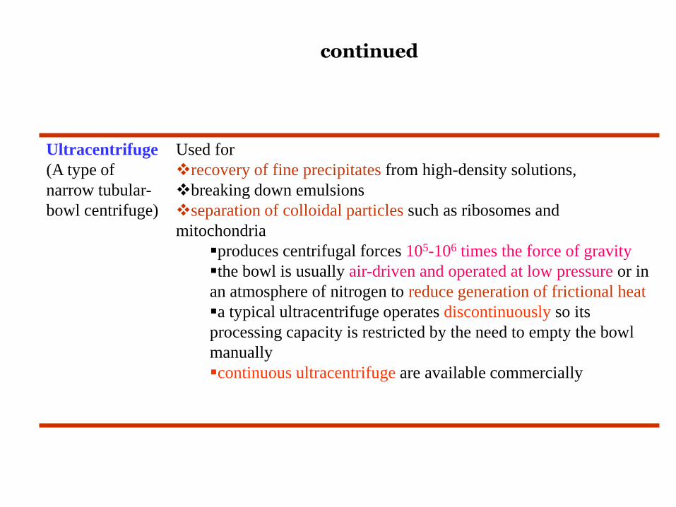
Ultracentrifuge
(A type of
narrow tubular-
bowl centrifuge)
Used for
recovery of fine precipitates from high-density solutions,
breaking down emulsions
separation of colloidal particles such as ribosomes and
mitochondria
produces centrifugal forces 105-106 times the force of gravity
the bowl is usually air-driven and operated at low pressure or in
an atmosphere of nitrogen to reduce generation of frictional heat
a typical ultracentrifuge operates discontinuously so its
processing capacity is restricted by the need to empty the bowl
manually
continuous ultracentrifuge are available commercially
continued
Disc-stack
bowl
centrifuge
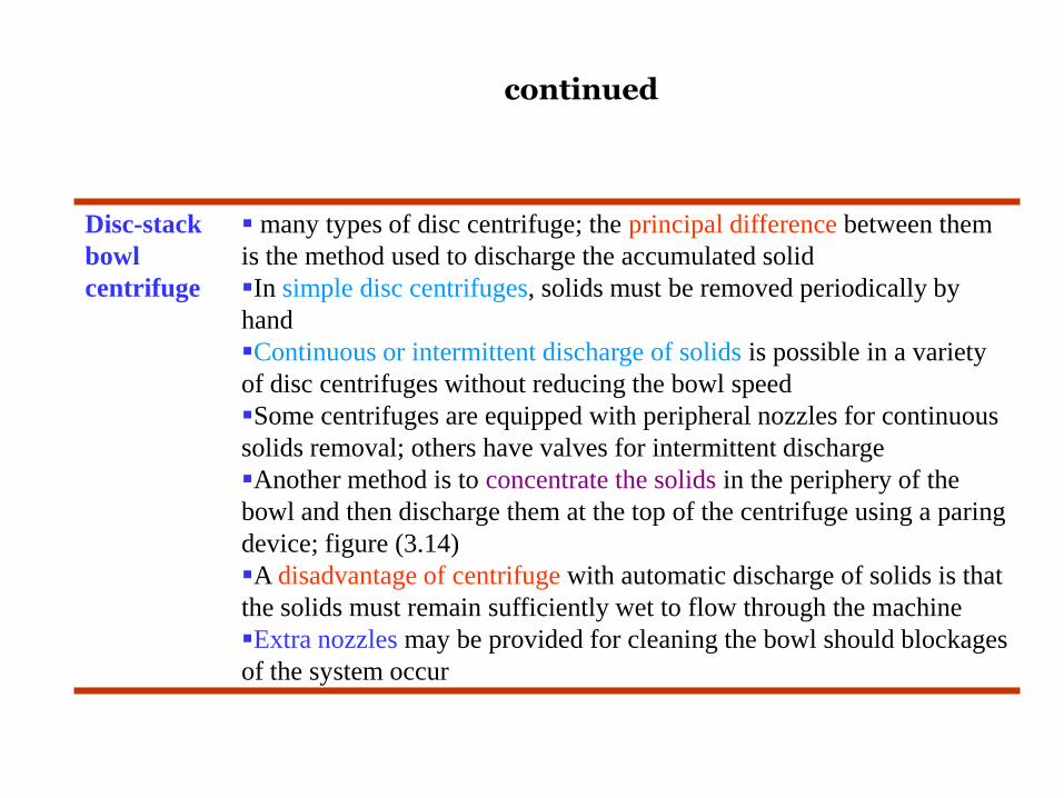
many types of disc centrifuge; the principal difference between them
is the method used to discharge the accumulated solid
In simple disc centrifuges, solids must be removed periodically by
hand
Continuous or intermittent discharge of solids is possible in a variety
of disc centrifuges without reducing the bowl speed
Some centrifuges are equipped with peripheral nozzles for continuous
solids removal; others have valves for intermittent discharge
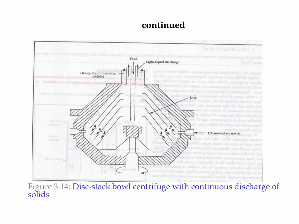
Another method is to concentrate the solids in the periphery of the
bowl and then discharge them at the top of the centrifuge using a paring
device; figure (3.14)
A disadvantage of centrifuge with automatic discharge of solids is that
the solids must remain sufficiently wet to flow through the machine
Extra nozzles may be provided for cleaning the bowl should blockages
of the system occur
continued
Figure 3.14: Disc-stack bowl centrifuge with continuous discharge of solids
continued
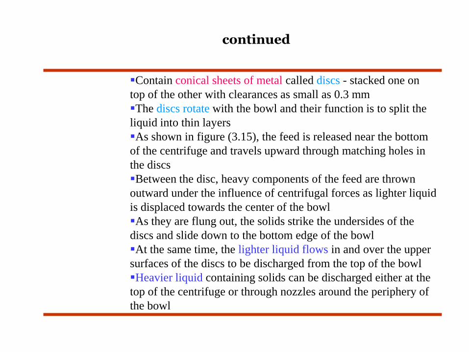
Contain conical sheets of metal called discs - stacked one on
top of the other with clearances as small as 0.3 mm
The discs rotate with the bowl and their function is to split the
liquid into thin layers
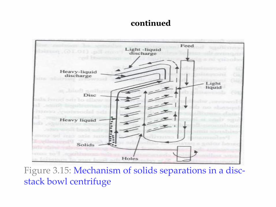
As shown in figure (3.15), the feed is released near the bottom
of the centrifuge and travels upward through matching holes in
the discs
Between the disc, heavy components of the feed are thrown
outward under the influence of centrifugal forces as lighter liquid
is displaced towards the center of the bowl
As they are flung out, the solids strike the undersides of the
discs and slide down to the bottom edge of the bowl
At the same time, the lighter liquid flows in and over the upper
surfaces of the discs to be discharged from the top of the bowl
Heavier liquid containing solids can be discharged either at the
top of the centrifuge or through nozzles around the periphery of
the bowl
continued
Figure 3.15: Mechanism of solids separations in a disc-stack bowl centrifuge
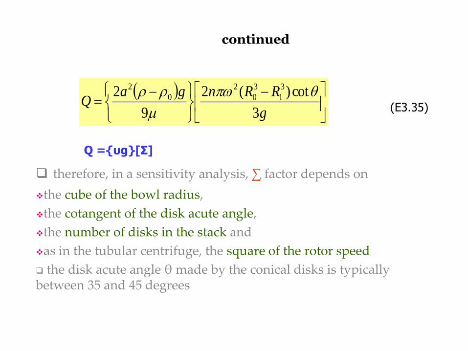
continued
therefore, in a sensitivity analysis, ∑ factor depends on
the cube of the bowl radius,
the cotangent of the disk acute angle,
the number of disks in the stack and
as in the tubular centrifuge, the square of the rotor speed
the disk acute angle θ made by the conical disks is typically between 35 and 45 degrees
g
RRngaQ
3
cot)(2
9
2 3
1
3
0
2
0
2
(E3.35)
Q ={υg}[Σ]
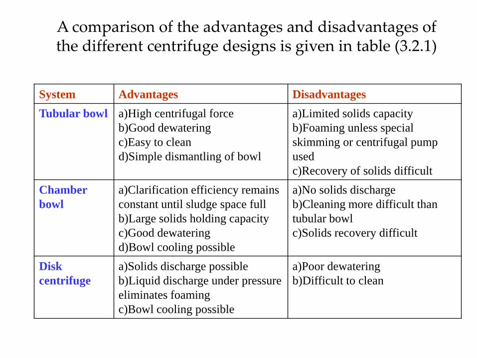
System Advantages Disadvantages
Tubular bowl a)High centrifugal force
b)Good dewatering
c)Easy to clean
d)Simple dismantling of bowl
a)Limited solids capacity
b)Foaming unless special
skimming or centrifugal pump
used
c)Recovery of solids difficult
Chamber
bowl
a)Clarification efficiency remains
constant until sludge space full
b)Large solids holding capacity
c)Good dewatering
d)Bowl cooling possible
a)No solids discharge
b)Cleaning more difficult than
tubular bowl
c)Solids recovery difficult
Disk
centrifuge
a)Solids discharge possible
b)Liquid discharge under pressure
eliminates foaming
c)Bowl cooling possible
a)Poor dewatering
b)Difficult to clean
A comparison of the advantages and disadvantages of the different centrifuge designs is given in table (3.2.1)
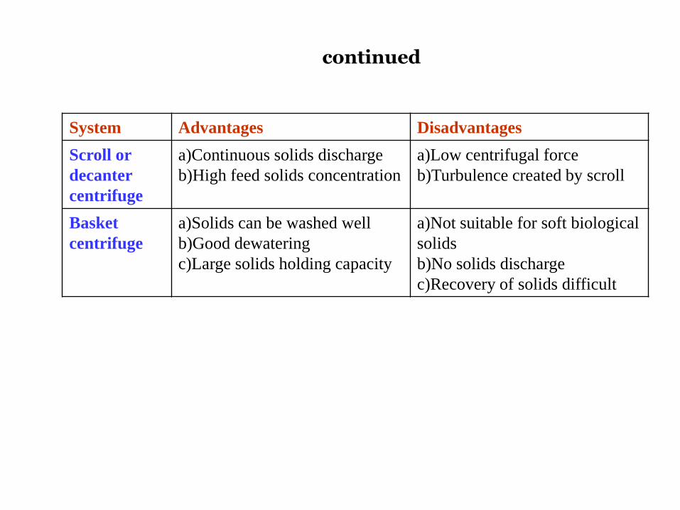
continued
System Advantages Disadvantages
Scroll or
decanter
centrifuge
a)Continuous solids discharge
b)High feed solids concentration
a)Low centrifugal force
b)Turbulence created by scroll
Basket
centrifuge
a)Solids can be washed well
b)Good dewatering
c)Large solids holding capacity
a)Not suitable for soft biological
solids
b)No solids discharge
c)Recovery of solids difficult
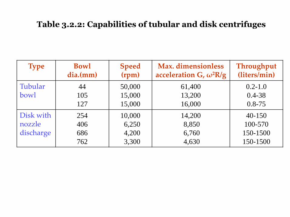
Table 3.2.2: Capabilities of tubular and disk centrifuges
Type Bowl dia.(mm)
Speed (rpm)
Max. dimensionless acceleration G, ω2R/g
Throughput (liters/min)
Tubular bowl
44
105
127
50,000
15,000
15,000
61,400
13,200
16,000
0.2-1.0
0.4-38
0.8-75
Disk with nozzle discharge
254
406
686
762
10,000
6,250
4,200
3,300
14,200
8,850
6,760
4,630
40-150
100-570
150-1500
150-1500


