64
Mechanical Seal Products and Services Catalog

Mechanical Seal Products and Services Catalog
2
A Global Leader, A Trusted PartnerFlowserve is the recognized world leader in supplying pumps, seals, valves and associated services to the power, oil, gas, chemical and general industries. Every day our solutions move even the most hazard-ous fluids and gases safely and securely. Flowserve represents not only a collection of trusted products, but also a single global source that can reduce your total cost of ownership.
Instrumental in this process is the Flowserve line of mechanical seals, support systems and services for pumps and other rotating equipment. These technologically advanced products assist our customers in attaining their goals of increasing reliability and improving process management.
A Guide to Flowserve Seals
This catalog will familiarize you with select mechanical seal products, seal support systems and services designed to improve rotating equipment operations. Industry applications are provided as well as operating parameters, features and equipment suitability for individual products. The symbols shown here are used as a quick reference to help identify the primary industry application.
For more information about Flowserve and to find a location near you, visit our website: www.flowserve.com.
Oil and Gas
Power
Water Resources
Mineral and Ore Processing
Pulp and Paper
Pharmaceutical
General Industry
Chemical

3
Introduction . . . . . . . . . . . . . . . . . . . . . . . . . . . . . 4
Refining & Petroleum Industry. . . . . . . . . . . . . . . 6
Chemical Industry . . . . . . . . . . . . . . . . . . . . . . . . 7
Power Industry. . . . . . . . . . . . . . . . . . . . . . . . . . . 8
Pipeline Industry . . . . . . . . . . . . . . . . . . . . . . . . . 9
Pulp & Paper Industry . . . . . . . . . . . . . . . . . . . . 10
Mineral and Ore Processing Industry. . . . . . . . . 11
Water & Wastewater Industry . . . . . . . . . . . . . . 12
Pharmaceutical Industry . . . . . . . . . . . . . . . . . . 13
ISC2 Standard Cartridge Seals . . . . . . . . . . . . . . 14
Pusher Seals . . . . . . . . . . . . . . . . . . . . . . . . . . . 17
Metal Bellows Seals . . . . . . . . . . . . . . . . . . . . . . 22
Mixer Seals. . . . . . . . . . . . . . . . . . . . . . . . . . . . . 25
Compressor Seals . . . . . . . . . . . . . . . . . . . . . . . 29
Slurry Seals . . . . . . . . . . . . . . . . . . . . . . . . . . . . 35
Gas Barrier and Containment Seals . . . . . . . . . . 38
OEM and Special Duty Seals . . . . . . . . . . . . . . . 41
Seal Support Systems . . . . . . . . . . . . . . . . . . . . 45
Accessories . . . . . . . . . . . . . . . . . . . . . . . . . . . . 50
Seal Design and Operation . . . . . . . . . . . . . . . . . 53
Mechanical Seal Piping Plans. . . . . . . . . . . . . . . 60
Table of Contents

4
Global Presence, Local SupportResponsiveness Worldwide
Globally, Flowserve operates regional, state-of-the-art manufacturing facilities to provide sealing solutions as a single resource for the improvement of end user customer rotating equipment operations. In cooperation with our alliance customers, we have improved operational efficiencies to world-class standards.
Alliances / LifeCycle Advantage
Flowserve is the undisputed global leader in delivering Total Cost of Ownership (TCO) programs to the fluid handling marketplace because we have the technologi-cal leadership, product breadth, service and support, financial stability, and experience with reliability focused programs. With hundreds of successful alliances, Flowserve stands by its documented results and customer references. An alliance customer can select from a variety of programs or create a unique arrangement that best suits their needs, including regional and global plans.
With assistance from the Flowserve Services and Solutions team, all engagements are tailored to meet customer priorities and business strategies. The result is a formal program called LifeCycle Advantage™, a partnership that incorporates performance indicators to measure success and a commercial structure that aligns with customer goals. From traditional arrangements to performance-based, risk-reward contracts, Flowserve has experience designing and administering agreements that help achieve customer business goals.
Quick Response Centers (QRCs)
To meet the end user need for cost reduction, increased seal life and minimal down time, Flowserve has developed a network of Quick Response Centers (QRCs). Strategically located around the world, QRCs are staffed by highly skilled engineers and technicians who are available around the clock, seven days a week, to respond to customer inquiries, evaluate and troubleshoot problems, and provide reliable solutions with quantifiable business results.
Typical facilities are equipped with modern manufacturing capabilities including seal repair and reconditioning as well as the ability to design and produce complete seals. QRCs include complete CAD resources with the ability to quickly design detailed drawings for parts or seals. With this level of local customer focus, the Quick Response Centers are ready to respond to your needs quickly and completely.
5
Flowserve employs a comprehensive collection of tools and technologies to ensure all relevant equipment, unit and plant data becomes part of the decision-making process. Whether employing a wireless monitoring system, leveraging its Technology Advantage™ Platform or making sense of disparate sets of historical data, Flowserve can help customers get a more complete view of all their data, including live operational parameters. Asset technologies include:
• IntelligentProcessSolutionsWireless (IPS Wireless™)
•ConditionDataPointMonitoring(CDPM)
•Advancedvibrationmeasurementsanddiagnostics
•Specialfieldperformancetesttools
Once data is collected, proprietary software in Flowstar.net and IPS APEX™ from Flowserve allows customers to view actionable information using easy-to-understand graphical interfaces. Flowserve and customer experts then collaborate to determine the meaning of data and quickly deploy solutions prevent-ing equipment failures and system disruptions before they occur.
Asset Data Management and Educational Resources
Educational Resources
Flowserve education and training provide companies around the world with a wide range of innovative programs focused on helping plant operators, reliability specialists, engineers and maintenance personnel deepen their understanding of flow management equipment and systems. Training programs from Flowserve are ideal for organizations seeking:
•Maximizedplantassetavailabilityand equipment reliability
• Increasedmeantimebetweenrepair(MTBR)
•Workforcedevelopmentforincreasing proficiency in the installation, design, operation, maintenance and repair of flow management equipment and systems
Customers can choose the location, course content and program formats that optimize the use of human and financial resources and deliver the most effective results. The learning venues vary depending on the type of training requested and can take place at the customer's site, a Flowserve regional Learning Resource Center or online.
While customers may select from a menu of standard course offerings, customer training is frequently tailored to address specific require-ments based on audience or flow management system issues. A Flowserve education and train-ing expert can help develop a program that addresses specific customer goals.
6
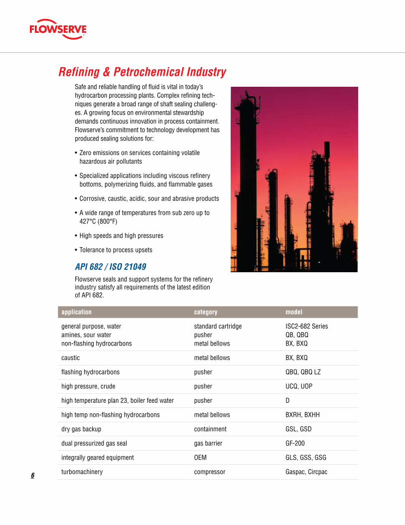
Refining & Petrochemical IndustrySafe and reliable handling of fluid is vital in today’s hydrocarbon processing plants. Complex refining tech-niques generate a broad range of shaft sealing challeng-es. A growing focus on environmental stewardship demands continuous innovation in process containment. Flowserve’s commitment to technology development has produced sealing solutions for:
•Zeroemissionsonservicescontainingvolatile hazardous air pollutants
•Specializedapplicationsincludingviscousrefinery bottoms, polymerizing fluids, and flammable gases
•Corrosive,caustic,acidic,sourandabrasiveproducts
•Awiderangeoftemperaturesfromsubzeroupto 427°C (800°F)
•Highspeedsandhighpressures
•Tolerancetoprocessupsets
API 682 / ISO 21049 Flowserve seals and support systems for the refinery industry satisfy all requirements of the latest edition of API 682.
application category model
general purpose, water standard cartridge ISC2-682 Series amines, sour water pusher QB, QBQ non-flashing hydrocarbons metal bellows BX, BXQ
caustic metal bellows BX, BXQ
flashinghydrocarbons pusher QBQ,QBQLZ
high pressure, crude pusher UCQ, UOP
high temperature plan 23, boiler feed water pusher D
hightempnon-flashinghydrocarbons metalbellows BXRH,BXHH
dry gas backup containment GSL, GSD
dual pressurized gas seal gas barrier GF-200
integrally geared equipment OEM GLS, GSS, GSG
turbomachinery compressor Gaspac, Circpac

7
Chemical IndustryModern chemical plants produce a tremendous variety of products over a wide range of operating conditions. Next to safe handling of toxic products, good corrosion resistance, reliability and low cost are of great importance.
Critical needs are: •Resistancetohighlycorrosiveliquids
•Awiderangeofmaterialsofconstruction
•Resistancetoabrasivesubstances
•Abilitytostandupunderhighlytoxic,volatile and flammable fluid service
•Lowleakageratesorzeroproductleakage
•Lowcostbutdurabledesignsforstuffingboxretrofits
•Maximuminterchangeabilityofcomponents to reduce inventories
ASME / ISO / JIS Flowserve has a wide range of products to cover ASME (ANSI), ISO (DIN and EN) and JIS pump standards, which are most commonly used in the chemical industry. Engineered designs for pumps and mixers are also part of the product range.
application category model
standard cartridge ISC2 Series most low viscosity, mildly corrosive chemicals, pusher RO, Europac 600-610 water, process water, caustics, mild acids, metal bellows BX, BXLS non-flashing low temperature hydrocarbons slurry Allpac special duty Pac-Seal
hightemperature/heattransfer metalbellows BXHH,BXRH
high viscosity, slurry slurry SLM, Allpac
most clean, low viscosity chemicals gas barrier GX-200, GF-200
acids, corrosive chemicals pusher RA, RA-C
integrally geared equipment OEM GLS/GSS/GSG
mixer M Series, Mixerpac mixers mixer VRA, MSS standard cartridge ISC2-MW

8
Power IndustryAs generating stations continue to increase in size, out-put and complexity, sealing devices with an ever-greater range of speed, pressure and temperature capability are required. In hot water applications, these factors create difficult lubrication conditions between the seal faces requiring specialized solutions in materials, cooling fea-tures, and seal face features to achieve long mechanical seal life.
In the critical sealing of boiler feed and boiler circulation water, Flowserve continues to innovate new technology to optimize and extend performance. Station operators turn to Flowserve to provide a safer, lower maintenance working environment.
Flowserve development has created solutions for:
•Highspeedsonlargeshaftdiameters
•Highpressuresandhightemperaturesonwater
•Minimumreactiontotemperaturetransients
•Hotstandbyandslowrollcapability
•Electrocorrsioneffectsapparentinhighpurity feed water
•Abrasiveslurriesusedinfluegasdesulphurization
application temperature pressure cooling category model
water, condensate low low none standard cartridge ISC2 Series low low none special duty PSS III
medium medium none pusher QBU boiler feed water medium medium Plan 23 pusher Europac 615 high high Plan 23 pusher D, DP high veryhigh Plan23 pusher DHTW
blowers high low none special duty Circpac MD
low low none slurry SLM flue gas desulphurization low low none slurry SLC low low none slurry RIS

9
Pipeline IndustryPipelines are an economical and reliable way to transport large quantities of liquid when the unique characteristics of the complete system are addressed. Pipelines move fluids within the natural resource recovery region, trans-port raw products to refineries, and transfer refined prod-ucts to distribution points. Operators may use batch type transport to send various refined products ranging from fuel oils to Liquefied Natural Gas (LNG), often at varying pressures through a single pipeline.
Supercritical fluids which normally exist as gases, such as ethane, CO2, and natural gas are pumped in their dense phase and pose unique sealing challenges.
Mechanical seals are relied on to seal critical pumps in remote locations without access to clean flush fluids and provide operators early leakage detection so they can react in time to prevent spills.
Flowserve applies industry-leading technology in proven products that meet these special pipeline industry needs:
•Dependableperformanceinunattendedmainand booster station service
•Operationunderhighpressuresandveryhighspeeds
•Abilitytohandleawidearrayoffluidsofvarying specific gravities from light hydrocarbons to viscous crude bitumen
application pressure category model
flashinglighthydrocarbons medium pusher QBQ,QBQLZ
low metal bellows BXQ hydrocarbons, crude oil medium pusher QBQ high pusher HSH,UOP veryhigh pusher UHTW
dry lift-off gas back-up medium containment GSL
low metal bellows BX produced water medium slurry Allpac medium pusher QB veryhigh pusher UHTW
dense phase fluids, CO2 veryhigh pusher UHTW,GaspacT
•Supercritical,densephasefluids
•Highresistancetodirtandabrasives
•Reliablesealingandlowleakagedespite radical fluctuations in temperature
•Performanceinintermittentservice,with many stops and high pressure start-ups

10
Pulp & Paper IndustryPaper stock, black liquor, chlorine, coating mixes, pumps, refiners, screens and agitators are common in the pulp and paper industry. Processing wood or waste paper and transforming it into paper or board requires cutting, grinding, cleaning, bleaching and de-watering operations. Reduction of energy and water usage is important to reduce operating cost. Flowserve has developed advanced seals and sealing systems that can help you reduce your plant's water, energy and maintenance costs:
•Resistancetohighlycorrosiveliquids
•Resistancetoabrasivesubstances
•Awiderangeofmaterialsofconstruction
•Lowleakagerates
•Lowcostbutdurabledesignsforstuffingboxretrofits
•Maximuminterchangeabilityofcomponents to reduce inventories
application equipment category model
pumps standard cartridge ISC2 Series paper stock pumps special duty PSS III pumps slurry SLM, Allpac
refiners, conveyors bellows BX specialty equipment axial flow circulators special duty PSS III pulpers slurry SLM

11
Mineral and Ore Processing IndustryAlumina, cement, clay, coal, copper, gold, gypsum, mineral sands, nickel, phosphate, potash, silver, trona, taconite, titanium, zinc; whatever the process, mineral and ore can represent one of the toughest machinery and sealing environments around. Taking raw material from the earth and refining finished mineral products requires rugged equipment capable of surviving abra-sive and corrosive services, often at extreme pressures and temperatures.
Flowserve delivers advanced sealing systems to decrease maintenance expenditures, limit or eliminate water usage, maintain safety and reliability, and help reduce plant energy costs. Our products and services are designed to accomplish all this while ensuring equipment availability with increased meantime between planned maintenance, ultimately allowing for higher production by having:
•Resistancetohighlyabrasiveliquidslurries
•Resistancetohighlycorrosivesubstances
•Awiderangeofmaterialsofconstructionforlong seal life
•Maximuminterchangeabilityofcomponentsto reduce inventories
•Abilitytoisolatehighlytoxicandcorrosivefluids from the atmosphere
application slurry category model
heavy slurry SLC, SLM-6200 slurry pumps medium slurry SLM-6000, Allpac light standard cartridge ISC2 Series
agitators / autoclave mixer seal M Series
accessories accessories SLD, QCD, EPD
axial flow circulators special duty PSS III
•Recoverabilityfromloworlostsuction upset conditions
•Noproductdilutingflushrequirements

12
Water & Wastewater IndustryWater is the most common liquid on earth yet is a precious commodity and deserving of sustainable handling. It is used for many purposes, such as drinking, cooling, heating, irrigation, processing and sanitation.
Wastewater treatment plants have two basic purposes: to speed up the purification process occurring naturally in rivers, lakes and streams, and to reduce toxic con-taminants that can that can interfere with natural pro-cesses. Typical applications can involve chemicals, sol-ids and slurries.
As government regulations on water quality increase, the cost of water treatment and the value of clean water increase. Flowserve seals and sealing systems can offer a significant savings in operating costs:
•Lowleakagerates
•Reliability
•Resistancetocontaminationandabrasives
•Lowcostbutdurabledesignsforstuffingboxretrofits
application category model
standard cartridge ISC2 Series pusher RO water pusher Europac 600-610 special duty PSS III special duty Pac-Seal
sludge slurry SLM slurry Allpac
•Maximuminterchangeabilityofcomponents to reduce inventories
•Reduceoreliminateenvironmental contamination

13
Pharmaceutical IndustryContinuous development of new drugs and healthcare products expand the capabilities and challenges of the pharmaceutical industry. Manufacturers of pharmaceu-tical products likewise refine their processes to improve the performance of their rotating equipment and remain compliant with regulations. Lower emissions and improved purity of end products are the two main focuses with sealing rotating equipment, along with being a good community neighbor.
Flowserve has close relationships with many of the end users and specialty equipment manufacturers and knows the industry requirements:
•Noproductcontaminationallowed
•Lowornoemissionstoatmosphere
•Awiderangeofmaterialsofconstructionincluding food grade compatible
•Lowleakagerates
•Electropolishfinishesavailableoncriticalmetal surfaces for ease of cleaning and increased sanitary protection
•Sanitaryglandsanddebriswells
•Applicationexperiencesealinghigh-alloyand glass-lined vessels
application category remark model
mixer wet or dry dual pressurized M Series mixers, agitators, mixer CIP/SIP dry lift-off dual Mixerpac 2568 / 2570 blenders, dryers standard cartridge wet dual pressurized ISC2-MW mixer dry contacting single VRA mixer split seal MSS
mixer wet dual pressurized MW-200 autoclaves, centrifuges mixer dry contacting dual pressurized MD-200 mixer dry lift-off dual pressurized ML-200
bioreactors mixer bottom entry ST mixer side entry Mixerpac 589
pumps standard cartridge single or dual ISC2 Series special duty split seal PSS III
•Alonghistoryofexperiencesealingtopentry, side entry and bottom entry mixer and agitator equipment with great success
•Verylowspeedstoveryhighspeedswithgas seal designs
•Cryogenicvacuumstoveryhighpressureand high temperature autoclaves with dual seals
•Sealsaredesignedforclean-in-place(CIP) and steam-in-place (SIP) applications as well as the ability to stand up to caustics and acid flushes between batches
ISC2 Standard Cartridge Seals
14
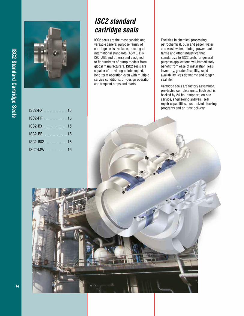
ISC2 standard cartridge sealsISC2 seals are the most capable and versatile general purpose family of cartridge seals available, meeting all international standards (ASME, DIN, ISO, JIS, and others) and designed to fit hundreds of pump models from global manufacturers. ISC2 seals are capable of providing uninterrupted, long-term operation even with multiple service conditions, off-design operation and frequent stops and starts.
Facilities in chemical processing, petrochemical, pulp and paper, water and wastewater, mining, power, tank farms and other industries that standardize to ISC2 seals for general purpose applications will immediately benefit from ease of installation, less inventory, greater flexibility, rapid availability, less downtime and longer seal life.
Cartridge seals are factory assembled, pre-tested complete units. Each seal is backed by 24-hour support, on-site service, engineering analysis, seal repair capabilities, customized stocking programs and on-time delivery. ISC2-PX . . . . . . . . . . . . 15
ISC2-PP . . . . . . . . . . . . 15
ISC2-BX . . . . . . . . . . . . 15
ISC2-BB . . . . . . . . . . . . 16
ISC2-682 . . . . . . . . . . . 16
ISC2-MW . . . . . . . . . . . 16
15
15
16
16
16

ISC2 Standard Cartridge Seals
15
Equipment Type• GeneralpurposeASME,ISO,JIS pumps Operating ParametersPressure up to 20.6 bar (300 psi)
Temperature -40 to 204°C (400°F)
Speed up to 23 m/s (75 fps)
Shaft Sizes 25 to 200 mm (1.000 to 8.000 inch)
Features• Singlecartridgepusherseals
• Appliedinawidevarietyofgeneral purpose industrial applications and equipment
• Thermalmanagementtechnology helps the seal run cooler and tolerate dry running events
• Stationaryfacesupportdrive mechanism reduces wear in applications with high vibration levels
• Forsizeslargerthan70mm (2.750 inch), the stationary support drive mechanism allows a larger range of dynamic movement commonly found in larger equipment
• Throttlebushingprovidessafe containment in the unlikely event of a seal failure
•Springsandpinsareoutsidethe product for reduced corrosion
• Availableinawiderangeofmaterials
Reference FSD243
ISC2-PXSingle cartridge pusher seals
Equipment Type• GeneralpurposeASME,ISO,JIS pumps Operating ParametersPressure up to 20.6 bar (300 psi)
Temperature -40 to 204°C (400°F)
Speed up to 23 m/s (75 fps)
Shaft Sizes 25 to 200 mm (1.000 to 8.000 inch)
Features• Dualcartridgepusherseals
• Appliedinawidevarietyofgeneral purpose industrial applications and equipment
• Advanceddesignvolutegrove significantly increases barrier fluid flow to promote cool running
• Thesealarrangementsaretandem and double balanced to allow both pressurized and unpressurized operation
• Stationaryfacesupportdrive mechanism reduces wear in applications with high vibration levels
• Forsizeslargerthan70mm (2.750 inch), the stationary support drive mechanism allows a larger range of dynamic movement commonly found in larger equipment
•Springsandpinsareoutsidethe product for reduced corrosion
• Availableinawiderangeofmaterials
Reference FSD243
ISC2-PPDual cartridge pusher seals
Equipment Type• GeneralpurposeASME,ISO,JIS pumps Operating ParametersPressure up to 13.8 bar (200 psi)
Temperature -40 to 204°C (400°F)
Speed up to 23 m/s (75 fps)
Shaft Sizes 25 to 95 mm (1.000 to 3.750 inch)
Features• Singlecartridgemetalbellowsseals
• Appliedinawidevarietyofgeneral purpose industrial applications and equipment
• Thermalmanagementtechnology helps the seal run cooler and tolerate dry running events
• Edge-weldedbellowsofAlloyC-276 metallurgy are well suited for a wide range of chemical environments
• Metalsbellowsmaintainexcellentseal face loading without hanging up due to solids build-up
• Throttlebushingprovidessafe containment in the unlikely event of a seal failure
• Availableinawiderangeofmaterials
Reference FSD243
ISC2-BXSingle metal bellows seals

ISC2 Standard Cartridge Seals
16
Equipment Type• GeneralpurposeASME,ISO,JIS pumps Operating ParametersPressure up to 13.8 bar (200 psi)
Temperature -40 to 204°C (400°F)
Speed up to 23 m/s (75 fps)
Shaft Sizes 25 to 95 mm (1.000 to 3.750 inch)
Features• Dualcartridgemetalbellowsseals
• Appliedinawidevarietyofgeneral purpose industrial applications and equipment
• Advanceddesignvolutegroove significantly increases barrier fluid flow to promote cool running
• Thesealarrangementsaretandem and double balanced to allow both pressurized and unpressurized operation
• Edge-weldedbellowsofAlloyC-276 metallurgy are well suited for a wide range of chemical environments
• Availableinawiderangeofmaterials
Reference FSD243
ISC2-BBDual metal bellows seals
Equipment Type• API610orASMEenlargedbore pumps Operating ParametersPressure pusher up to 20.6 bar (300 psi) bellows up to 13.8 bar (200 psi)
Temperature -40 to 204°C (400°F)
Speed up to 23 m/s (75 fps)
Shaft Sizes pusher 25 to 200 mm (1.000 to 8.000 inch) bellows 25 to 95 mm (1.000 to 3.750 inch)
Features• SealssatisfyallAPI682designand qualification test requirements
• ConfigurableaseitherTypeApusher seal or Type B metal bellows seal to suit specific applications
• AvailableinallAPI682standard arrangements including single, dual unpressurized and dual pressurized
• DesignsarebuiltonISC2sealbasic components, sharing the benefits of thermal management technology, volute groove design and Alloy C-276 bellows
• Builtforgeneraldutyrefineryand chemical plant services
Reference FSD243
ISC2-682ISC2 seals compliant to API 682
Equipment Type• Mixers Operating ParametersPressure up to 6.9 bar (100 psi)
Temperature -40 to 204°C (400°F)
Speed up to 1.1 m/s (3.5 fps)
Shaft Sizes 25 to 200 mm (1.000 to 8.000 inch)
Features• Economicalcartridgesealfortop entry installations
• Dualwetdesign
• Thermalmanagementtechnology helps the seal run cooler and tolerate dry running events
• 1.14mm(0.045inch)TIRonsizesup to 89 mm (3.500 inch) shaft size
• 1.52mm(0.060inch)TIRonsizes greater than 89 mm (3.500 inch) shaft size
• Volutegroovesignificantlyincreases barrier fluid flow to promote cool running even at mixer speeds
ISC2-MWDual pusher seal for mixer service
Pusher Seals
17
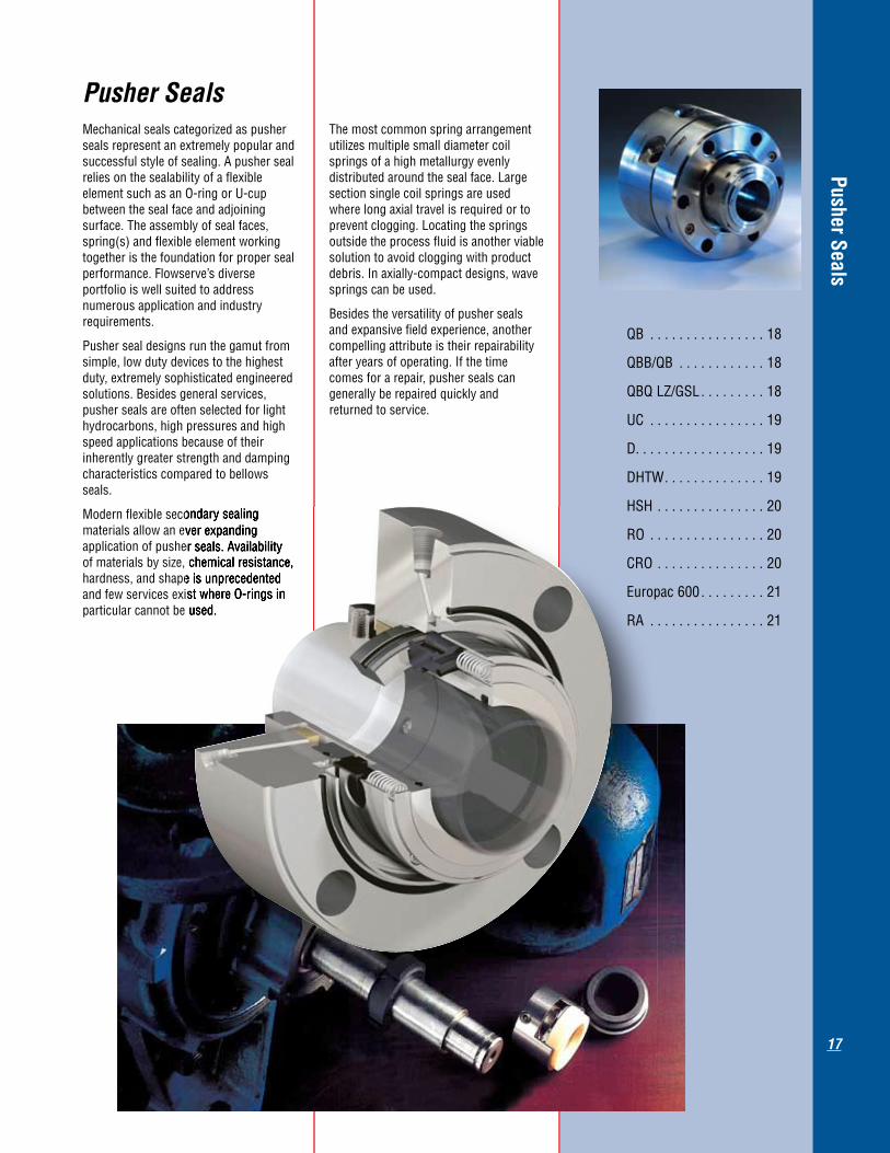
Pusher SealsMechanical seals categorized as pusher seals represent an extremely popular and successful style of sealing. A pusher seal relies on the sealability of a flexible element such as an O-ring or U-cup between the seal face and adjoining surface. The assembly of seal faces, spring(s) and flexible element working together is the foundation for proper seal performance. Flowserve’s diverse portfolio is well suited to address numerous application and industry requirements.
Pusher seal designs run the gamut from simple, low duty devices to the highest duty, extremely sophisticated engineered solutions. Besides general services, pusher seals are often selected for light hydrocarbons, high pressures and high speed applications because of their inherently greater strength and damping characteristics compared to bellows seals.
Modern flexible secondary sealing materials allow an ever expanding application of pusher seals. Availability of materials by size, chemical resistance, hardness, and shape is unprecedented and few services exist where O-rings in particular cannot be used.
The most common spring arrangement utilizes multiple small diameter coil springs of a high metallurgy evenly distributed around the seal face. Large section single coil springs are used where long axial travel is required or to prevent clogging. Locating the springs outside the process fluid is another viable solution to avoid clogging with product debris. In axially-compact designs, wave springs can be used.
Besides the versatility of pusher seals and expansive field experience, another compelling attribute is their repairability after years of operating. If the time comes for a repair, pusher seals can generally be repaired quickly and returned to service.
Modern flexible secondary sealing materials allow an ever expanding application of pusher seals. Availability of materials by size, chemical resistance, hardness, and shape is unprecedented and few services exist where O-rings in particular cannot be used.
QB . . . . . . . . . . . . . . . . 18
QBB/QB . . . . . . . . . . . . 18
QBQLZ/GSL . . . . . . . . . 18
UC . . . . . . . . . . . . . . . . 19
D. . . . . . . . . . . . . . . . . . 19
DHTW. . . . . . . . . . . . . . 19
HSH . . . . . . . . . . . . . . . 20
RO . . . . . . . . . . . . . . . . 20
CRO . . . . . . . . . . . . . . . 20
Europac 600 . . . . . . . . . 21
RA . . . . . . . . . . . . . . . . 21

Pusher Seals
18
QBGeneral purpose pusher seals
Equipment Type• Pumps,includingAPI610 Operating ParametersPressure up to 51.7 bar (750 psi)
Temperature -40 to 204°C (400°F)
Speed up to 23 m/s (75 fps)
Shaft Sizes 12.7 to 139.7 mm (0.500 to 5.500 inch)
Features• General industry single, balanced,
multi-spring, pusher seal
• Weldedkeysdriverotatingsealfaceproviding robustness to high torque scenarios
• Awiderangeofavailablefeaturesenable improved performance in challenging applications
• Choiceofthrottlebushingdesign:fixed, floating, segmented
Other Configurations
QBQ • StandardAPI682Arrangement1 Type A seal
• Highbalancesealfacedesignforlow emissions. Faces designed to suppress flashing and minimize heat generation in hydrocarbon applications
QBS •Singlespringdesignprovidesthe highest resistance to clogging and corrosion
QBU • Groovedfaceoptiondesignedforhot water applications where cooling water is not available
QBR • Reverseconfigurationwithstationary flexible element. Standard hydraulic decoking jet pump seal
Reference FSD152, FSD175
Equipment Type• Pumps,includingAPI610 Operating ParametersPressure up to 51.7 bar (750 psi)
Temperature -40 to 204°C (400°F)
Speed up to 23 m/s (75 fps)
Shaft Sizes 20 to 127 mm (0.787 to 5.000 inch)
Features• StandardAPI682Arrangement3 Type A seal for pressurized barrier configurations
• Extremelyrobusttoreverse pressurization with reverse pressure handling capabilities that far exceed conventional balanced seals
• Sealfacegeometryenablesuseof face to back configuration which is preferred in many dual seal applications
• Integralpumpingring
Other Configurations
QBQ/QBQ • StandardAPI682Arrangement2 Type A seal for use with a liquid buffer fluid
• Highbalancelowemissionsfor hydrocarbon down to 0.45 specific gravity
Reference FSD152
QBB/QBDual pressurized pusher seals capable of zero emissions
Equipment Type• Pumps,includingAPI610 Operating ParametersPressure up to 51.7 bar (750 psi)
Temperature -40 to 204°C (400°F)
Speed 6.1 to 23 m/s (20 to 75 fps)
Shaft Sizes 20 to 116 mm (0.787 to 4.567 inch)
Features•API682Arrangement2TypeAsealfor use with a buffer gas
• Speciallydesignedforlight hydrocarbons at low vapor pressure margin
• Precisionfacetopographycombats vaporization by increasing fluid pressure between the seal faces and reducing heat generation
• Specificgravitiesbetween0.4and0.6
• Dry-runninglift-offcontainmentseal provides near zero emissions and safety backup
Other ConfigurationsQBQ LZ/QBQ • API682Arrangement2TypeAseal for use with a liquid buffer fluid
Reference FSD216, FSD143
QBQ LZ/GSLDual unpressurized pusher seals with containment seals
Pusher Seals
19
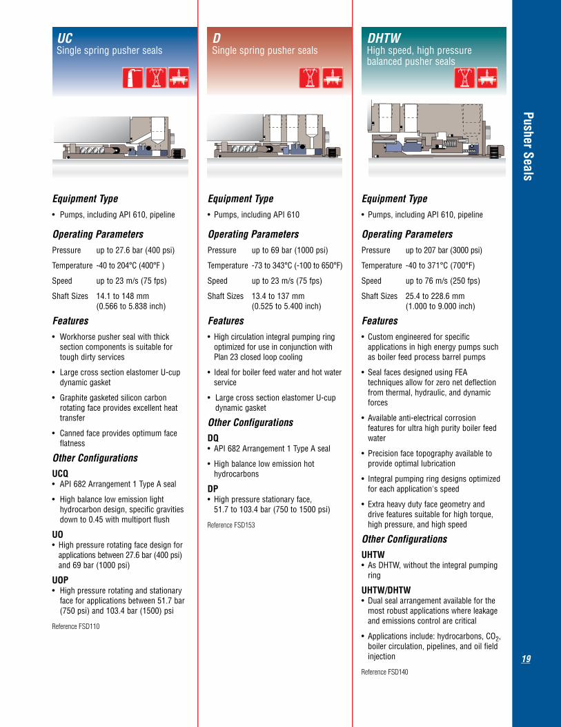
Equipment Type• Pumps,includingAPI610,pipeline Operating ParametersPressure up to 27.6 bar (400 psi)
Temperature -40 to 204°C (400°F )
Speed up to 23 m/s (75 fps)
Shaft Sizes 14.1 to 148 mm (0.566 to 5.838 inch)
Features• Workhorsepushersealwiththick section components is suitable for tough dirty services
• LargecrosssectionelastomerU-cup dynamic gasket
• Graphitegasketedsiliconcarbon rotating face provides excellent heat transfer
•Cannedfaceprovidesoptimumface flatness
Other Configurations
UCQ •API682Arrangement1TypeAseal
• Highbalancelowemissionlight hydrocarbon design, specific gravities down to 0.45 with multiport flush
UO • Highpressurerotatingfacedesignfor applications between 27.6 bar (400 psi) and 69 bar (1000 psi)
UOP • Highpressurerotatingandstationary face for applications between 51.7 bar (750 psi) and 103.4 bar (1500) psi
Reference FSD110
UCSingle spring pusher seals
Equipment Type• Pumps,includingAPI610 Operating ParametersPressure up to 69 bar (1000 psi)
Temperature -73 to 343°C (-100 to 650°F)
Speed up to 23 m/s (75 fps)
Shaft Sizes 13.4 to 137 mm (0.525 to 5.400 inch)
Features• Highcirculationintegralpumpingring optimized for use in conjunction with Plan 23 closed loop cooling
• Idealforboilerfeedwaterandhotwater service
• LargecrosssectionelastomerU-cup dynamic gasket
Other Configurations
DQ •API682Arrangement1TypeAseal
• Highbalancelowemissionhot hydrocarbons
DP • Highpressurestationaryface, 51.7 to 103.4 bar (750 to 1500 psi)
Reference FSD153
DSingle spring pusher seals
Equipment Type• Pumps,includingAPI610,pipeline Operating ParametersPressure up to 207 bar (3000 psi)
Temperature -40 to 371°C (700°F)
Speed up to 76 m/s (250 fps)
Shaft Sizes 25.4 to 228.6 mm (1.000 to 9.000 inch)
Features• Customengineeredforspecific applications in high energy pumps such as boiler feed process barrel pumps
• SealfacesdesignedusingFEA techniques allow for zero net deflection from thermal, hydraulic, and dynamic forces
• Availableanti-electricalcorrosion features for ultra high purity boiler feed water
•Precisionfacetopographyavailableto provide optimal lubrication
• Integralpumpingringdesignsoptimized for each application's speed
• Extraheavydutyfacegeometryand drive features suitable for high torque, high pressure, and high speed
Other Configurations
UHTW • AsDHTW,withouttheintegralpumping ring
UHTW/DHTW • Dualsealarrangementavailableforthe most robust applications where leakage and emissions control are critical
• Applicationsinclude:hydrocarbons,CO2, boiler circulation, pipelines, and oil field injection
Reference FSD140
DHTWHighspeed,highpressurebalanced pusher seals

Pusher Seals
20
ROUnbalanced pusher seals
Equipment Type• ASMEpumps Operating ParametersPressure up to 20.7 bar (300 psi)
Temperature -40 to 260°C (500°F)
Speed up to 23 m/s (75 fps)
Shaft Sizes 9.5 to 115 mm (0.375 to 4.500 inch)
Features• Single,unbalanced,multi-spring seals that can be used as an inside or outside seal
• Useinabrasive,corrosiveandviscous fluids in chemical services
• Heavycrosssectionsoftherotary components resist high levels of corrosion
•Openrotatingspringcompressionunit aids in keeping solids from packing around the seal faces and improves removal of seal face generated heat
• Individualpartsarecompletely interchangeable and easy to replace
Other Configurations
RO-TT •Supplied with PTFE V-rings
Reference FSD155
Equipment Type• ASMEpumps Operating ParametersPressure up to 20.7 bar (300 psi)
Temperature -40 to 260°C (500°F)
Speed up to 23 m/s (75 fps)
Shaft Sizes 9.5 to 115 mm (0.375 to 4.500 inch)
Features• Singlespring,pushersealavailable in single or dual version (dual shown)
• Usewithwaterorsimilarviscosity product
• Frictionbetweendynamicgasketand pump shaft provides drive
• Metalpartsofthesealareisolated from pumped product to prevent possible chemical or abrasive attack
• Easytoinstall
Other Configurations
CRO-P • Positivedriveversioncanbeusedwith liquids having lubricating properties greater than that of water
Reference FSD169
CROCoil spring seals
Equipment Type• Pumps,includingAPI610,pipeline Operating ParametersPressure up to 103 bar (1500 psi)
Temperature -40 to 204°C (400°F)
Speed up to 46 m/s (150 fps)
Shaft Sizes 38.1 to 177.8 mm (1.500 to 7.000 inch)
Features• Builtforhighpressure,highspeed, highly viscous services
• Flexiblestatordesignallowsforhigh speed operation and adapts to handle pump casing misalignment in axial split pumps
• Anti-rotationlugsprovidehightorque capability
•Thickcross-sectionfacesdesigned with FEA techniques provide high pressure capabilty
• Lappedfacesupportsurfacesstabilize the effects of mechanical and thermal loads
Reference FSD156
HSHStationary spring design seals

Pusher Seals
21
Equipment Type• ISOpumps Operating ParametersPressure up to 10 bar (145 psi)
Temperature -40 to 220°C (430°F)
Speed up to 23 m/s (75 fps)
Shaft Sizes 10 to 100 mm (0.394 to 3.940 inch)
Features• Single,unbalanced,singlewavy spring seal
• Appliedonawiderangeofduties, primarily in the chemical industry
• Designedaccordingtometric DIN EN 12 756 standard to L1k
Other Configurations
Europac 610 • Balancedversionfitsasteppedshaft, pressure to 25 bar (360 psi)
Europac 615 • Equippedwithlube-groovedesignfor hot water services without cooling. Pressure 0 to 17.5 bar (255 psi), temperature -40 to 170°C (340°F)
Reference FSD128
Europac 600Single unbalanced, wavy spring seals
Equipment Type• Generalpurposepumps Operating ParametersPressure up to 27.6 bar (400 psi)
Temperature -40 to 177°C (350°F)
Speed up to 23 m/s (75 fps)
Shaft Sizes 13 to 127 mm (0.500 to 5.000 inch)
Features• Useinhighlycorrosivechemical services
• Sealfacesandelastomersaretheonly wetted components and are available in a wide range of materials for proper corrosion resistance
• Flexiblerotordesignishydraulically balanced to provide proper face loading for extended reliability
• Easytoinstall
Other Configurations
RA-C • Versionusedwithchemicalproducts in plastic, glass, and other non-metallic pumps. There are no wetted metal parts for the highest corrosion resistance
Reference FSD170
RASingle, outside mounted pusher seals

Metal Bellow
s Seals
22
Metal Bellows SealsWhile pusher seals have an intermedi-ate flexible element acting between a seal face and adjoining surface, metal bellows seals use an assembly of edge-welded metal leaflets as the flexibleelement.Highalloymetalbellows provide spring loading for face contact, create a pressure barrier for optimum seal performance and absorb axial shaft movement while retaining the seal face. Without a dynamic gasket, metal bellows seals are applied in a range of applications otherwise untenable with a dynamic gasket pusher seal design:
• Hightemperatureapplications up to 427°C (800°F)
• Largeaxialtravelrequirements especially at high temperatures
• Corrosivechemicalsthatdegrade elastomers and other dynamic gaskets
Rotating bellows have a beneficial self-cleaning action through centrifugal effects that resist clogging of process solids in the bellows. Solids and wear debris may accumulate on the atmospheric side of the seal faces without hanging up the dynamic contact of the seal faces. Stationary bellows applied to high temperature hydrocarbons are often fitted with a hot steam quench to avoid coking and potentially compromising seal integrity.
Flowserve has proven experience applying metal bellows seals to general and critical services, from hazardous chemicals to refinery processing including full compliance to API 682 requirements. Configured as single, dual unpressurized or dual pressurized, metal bellows seals provide a high degree of reliability and long term performance.
BX. . . . . . . . . . . . . . . . . 23
BXB/BX. . . . . . . . . . . . . 23
BXRH . . . . . . . . . . . . . . 23
BXHH . . . . . . . . . . . . . . 24
BXHHS/GSDH. . . . . . . . 24
BRC . . . . . . . . . . . . . . . 24
Metal Bellow
s Seals
23
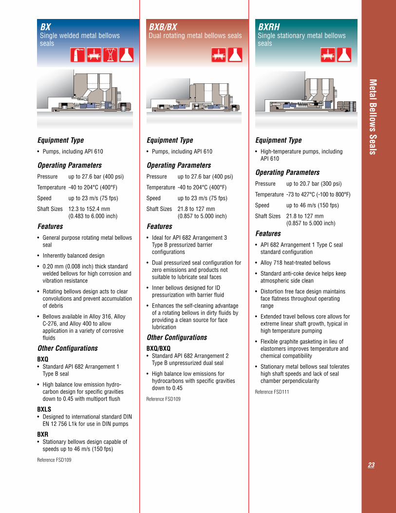
Equipment Type• Pumps,includingAPI610 Operating ParametersPressure up to 27.6 bar (400 psi)
Temperature -40 to 204°C (400°F)
Speed up to 23 m/s (75 fps)
Shaft Sizes 12.3 to 152.4 mm (0.483 to 6.000 inch)
Features• Generalpurposerotatingmetalbellows seal
• Inherentlybalanceddesign
• 0.20mm(0.008inch)thickstandard welded bellows for high corrosion and vibration resistance
• Rotatingbellowsdesignactstoclear convolutions and prevent accumulation of debris
• BellowsavailableinAlloy316,Alloy C-276, and Alloy 400 to allow application in a variety of corrosive fluids
Other Configurations
BXQ • StandardAPI682Arrangement1 Type B seal
• Highbalancelowemissionhydro- carbon design for specific gravities down to 0.45 with multiport flush
BXLS • DesignedtointernationalstandardDIN EN 12 756 L1k for use in DIN pumps
BXR • Stationarybellowsdesigncapableof speeds up to 46 m/s (150 fps)
Reference FSD109
BXSingle welded metal bellows seals
Equipment Type• Pumps,includingAPI610 Operating ParametersPressure up to 27.6 bar (400 psi)
Temperature -40 to 204°C (400°F)
Speed up to 23 m/s (75 fps)
Shaft Sizes 21.8 to 127 mm (0.857 to 5.000 inch)
Features• IdealforAPI682Arrangement3 Type B pressurized barrier configurations
• Dualpressurizedsealconfigurationfor zero emissions and products not suitable to lubricate seal faces
• InnerbellowsdesignedforID pressurization with barrier fluid
• Enhancestheself-cleaningadvantage of a rotating bellows in dirty fluids by providing a clean source for face lubrication
Other Configurations
BXQ/BXQ • StandardAPI682Arrangement2 Type B unpressurized dual seal
• Highbalancelowemissionsfor hydrocarbons with specific gravities down to 0.45
Reference FSD109
BXB/BXDual rotating metal bellows seals
Equipment Type• High-temperaturepumps,including API 610 Operating ParametersPressure up to 20.7 bar (300 psi)
Temperature -73 to 427°C (-100 to 800°F)
Speed up to 46 m/s (150 fps)
Shaft Sizes 21.8 to 127 mm (0.857 to 5.000 inch)
Features• API682Arrangement1TypeCseal standard configuration
• Alloy718heat-treatedbellows
• Standardanti-cokedevicehelpskeep atmospheric side clean
• Distortionfreefacedesignmaintains face flatness throughout operating range
• Extendedtravelbellowscoreallowsfor extreme linear shaft growth, typical in high temperature pumping
• Flexiblegraphitegasketinginlieuof elastomers improves temperature and chemical compatibility
• Stationarymetalbellowssealtolerates high shaft speeds and lack of seal chamber perpendicularity
Reference FSD111
BXRHSingle stationary metal bellows seals

Metal Bellow
s Seals
24
Equipment Type• High-temperaturepumps,including API 610 Operating ParametersPressure up to 20.7 bar (300 psi)
Temperature -73 to 427°C (-100 to 800°F)
Speed up to 19.8 m/s (57 fps)
Shaft Sizes 28.2 to 128.9 mm (1.110 to 5.073 inch)
Features• API682Arrangement2TypeCseal with dry running containment seal
• Alloy718heat-treatedbellows
• Steambuffergasmitigatesproduct coking in the buffer area and reduces heat loss from the product
• Vibrationdampeningfeaturesstabilize the containment seal bellows
• Containmentsealrunsdryforlong periods and is ready to take over if the primary seal leaks
• PipedwithaPlan75and/or76 containment system, very low product emissions are provided
Other Configurations
BXHHS/BXHHS • API682Arrangement2TypeCsealfor use with an unpressurized liquid buffer fluid
BXHHSB/BXHHS • API682Arrangement3TypeCdual face to back configuration pressurized barrier applications
BXHHS/GSDHHightemperaturecontainmentseals
Equipment Type• High-temperaturepumps,including API 610 Operating ParametersPressure up to 20.7 bar (300 psi)
Temperature -73 to 427°C (-100 to 800°F)
Speed up to 23 m/s (75 fps)
Shaft Sizes 28.2 to 128.9 mm (1.110 to 5.073 inch)
Features• API682Arrangement1TypeCseal alternate configuration
• Alloy718heat-treatedbellows
• Rotatingbellowsdesignactstoclear convolutions and prevent accumulation of debris
• Distortionfreefacedesignmaintains face flatness throughout operating range
• Extendedtravelbellowscoreallowsfor extreme linear shaft growth, typical in high temperature pumping
• Flexiblegraphitegasketinginlieuof elastomers improves temperature and chemical compatibility
• Provisionsforanti-cokingsteam quench included as standard
Other Configurations
BXHHS • API682Arrangement1TypeCseal alternate configuration
• Shorterversiondesignedtofit pumping equipment with axial length restrictions and when dual seals are required
BXHHSingle rotating metal bellows seals
Equipment Type• High-temperaturepumps,including API 610 Operating ParametersPressure up to 20.7 bar (300 psi)
Temperature -73 to 427°C (-100 to 800°F)
Speed up to 23 m/s (75 fps)
Shaft Sizes 28.2 to 150 mm (1.110 to 5.906 inch)
Features• API682Arrangement1TypeCseal alternate configuration
• Mostruggedbellowsavailable featuring 0.25 - 0.30 mm (10 - 12 mils) thick convolutions
• Alloy718heat-treatedbellowsandend adapters provide the highest resistance to stress corrosion cracking
• Applicationsinclude:cryogenic, corrosive, hydrocarbons, and heat transfer fluids
• Cannedfacedesigneliminatesshrink fit distortions
• Standardthreaded-onbellowsadapter
Other Configurations
BRCH • Utilizesaboltedbellowsadapterfor convenient repairs when necessary
BRCS • Shorterversiondesignedtofit pumping equipment with axial length restrictions and when dual seals are required
Reference FSD142
BRCSingle balanced rotating metal bellows seals

Mixer Seals
25
Mixer SealsIn chemical, pharmaceutical, food and oil refinery process plants, diverse systems are employed for agitating, blending and mixing products. Mixers, agitators, reactors, filters, dryers, and other specialty equipment require low maintenance operation and safety, both to protect the environment and the workplace. The mechanical seal design must provide excellent performance in the application, allowing for axial and radial shaft movements.
Flowserve is focused specifically to provide the best mixer sealing solutions:
•Liquidlubricated,drycontactingornoncontacting face technology
•Abilitytohandlesignificantradialandaxial shaft run-outs
•Cartridgedesignswithandwithout a bearing
•Top,bottomandsideentryseals
•Modulardesignsallowingeasypartreplacement
•Accommodationforsanitarygland/debris catcher for applications requiring steam cleaning
•Reversepressurecapabilityandemergency sealing solutions option
•Coolingflangeoption
•Numerouspre-engineereddesignsfitpopular OEM equipment
•Abilitytodesignandengineertocustomer and OEM specifications
•DesignsengineeredaccordingtoISOand international standards
•Materialsselectedforcorrosionresistance and long seal life
•Splitmixersealdesignsalloweasyinstallation without dismantling equipment
•Sterilizabledesignsavailable
•Sealsupportsystemstoenhancereliability
•Knowledgeableandexperiencedmixerseal team support
MW-200 . . . . . . . . . . . . 26
ML-200. . . . . . . . . . . . . 26
MD-200 . . . . . . . . . . . . 26
Mixerpac 2568 . . . . . . . 27
Mixerpac 581 . . . . . . . . 27
Mixerpac 589 . . . . . . . . 27
VRA . . . . . . . . . . . . . . . 28
MSS . . . . . . . . . . . . . . . 28
ST. . . . . . . . . . . . . . . . . 28replacement • Knowledgeable and experienced
seal team supportseal team support

Mixer Seals
26
Equipment Type• Mixers,agitators,blowers,fans Operating ParametersPressure vacuum to 6.7 bar (100 psi)
Temperature -40 to 150°C (300°F)
Speed up to 1.5 m/s (5 fps)
Shaft Sizes 40 to 220 mm
(1.575 to 9.000 inch)
Features• Contactinggasbarrierseal
• Productsidesealhasreverse pressure capability
• Dry-runningforminimizedproduct contamination from barrier fluid
• Featuresself-lubricatingfaces
• Coolingflangeforhighertemperatures up to 200°C (390°F) available
• Availablewithorwithoutbearing
• Optionalleakagecollectoratinboard seal
• Availableforsteelorglasslined vessels
• Optionalmaterialscompliantwith FDA CFR 21, USP Class VI, ADI Free Components and similar specifications
Other Configurations
MD-200 DIN
• Dimensionsandflangeconnectionsto DIN for steel or glass lined flanges
MD-100
• Singledryrunningseal
Reference FSD104
MD-200Top entry, dry contacting mixer seals
Equipment Type• Mixers,agitators,filters,filterdryers Operating ParametersPressure vacuum to 6.7 bar (100 psi)
Temperature -40 to 200°C (390°F)
Speed up to 10 m/s (33 fps)
Shaft Sizes 40 to 220 mm (1.575 to 9.000 inch)
Features• Noncontacting,lift-offgasbarrierseal
• Advancedlift-offtechnologyavoids wear from seal face contact
• Barrierleakagedoesnotaffectproduct quality
• Lowdragdesignforthedynamic O-ring (no hang-up)
• Operateswithasimplegasbarrier support system
• Optional with or without bearing
• Coolingflangeforhighertemperatures up to 300°C (570°F) available
•Sanitaryglandoptionforsterilization purposes
• Availableforsteelorglasslined vessels
• Optionalmaterialscompliantwith FDA CFR 21, USP Class VI, ADI Free Components and similar specifications
Other ConfigurationsML-200 DIN
• Dimensionsandflangeconnectionsto DIN for steel or glass lined flanges
• Withorwithoutbearing
Reference FSD104
ML-200Top entry, lift-off mixer seals
Equipment Type• Mixers,agitators,filters,filterdryers Operating ParametersPressure vacuum to 35 bar (500 psi)
Temperature -40 to 200°C (390°F)
Speed up to 4 m/s (13 fps)
Shaft Sizes 40 to 220 mm (1.575 to 9.000 inch)
Features• Liquidlubricatedseal
• Productsidesealhasreversepressure capability
• Balanceddualpressurizedseal
• Coolingcoiloptionsforhigher temperaturesavailable
• Coolingflangeforhighertemperatures up to 300°C (570°F) available
• Availablewithorwithoutbearing
• Designedforsteelorglasslined vessels
• Optionalmaterialscompliantwith FDA CFR 21, USP Class VI, ADI Free Components and similar specifications
Other Configurations
MW-200 DIN
• Dimensionsandflangeconnectionsto DIN for steel or glass lined flanges
• Withorwithoutbearing
Reference FSD104
MW-200Top entry, wet mixer seals

Mixer Seals
27
Equipment Type• Reactors,dryers Operating ParametersPressure vacuum to 40 bar (580 psi)
Temperature -40 to 200°C (390°F)
Speed up to 4 m/s (13 fps)
Shaft Sizes 40 to 400 mm (1.575 to 15.750 inch)
Features• Cartridgedesignwithbearing
• Liquidlubricatedseal
• Highpressureformedmetalbellows compensates to follow axial movements up to +/- 40 mm (1.575 inch)
• Balanceddualpressurizeddesign
• Perpendicularityofhousingtothe rotating shaft guided by bearings installed in the seal cartridge
Other ConfigurationsMixerpac 588
• Topandsideentrymixersealsfor sterile applications
• Bioreactorsandothers
• Highlyviscousorpulverizedproducts
• Optionalmaterialscompliantwith FDA CFR 21, USP Class VI, ADI Free Components and similar specifications
Reference FSD127
Mixerpac 589Horizontalentrymixersealsforlarge shaft movements
Equipment Type• Mixers,reactors,filters,filterdryers Operating ParametersPressure vacuum to 10 bar (145 psi)
Temperature -40 to 200°C (390°F)
Speed up to 10 m/s (33 fps)
Shaft Sizes 40 to 220 mm (1.575 to 9.000 inch)
Features• Noncontacting,lift-offgasbarrierseal
• Modularcatridgedesign
• Balanceddualpressurizeddesign
• Advancedlift-offtechnologyavoids wear, resulting from seal face contact
• Operateswithagasbarriersupport system
• Barrierleakagedoesnotaffect product side
• Construction with few gaps and crevices
•Easytoclean/sterilize
• Optionalmaterialscompliantwith FDA CFR 21, USP Class VI, ADI Free Components and similar specifications
Other ConfigurationsMixerpac 2570
• Lift-offsealforglasslinedvessels
• Allwettedpartsmetalfree
Reference FSD133
Mixerpac 2568Top entry mixer seals for sterile applications
Equipment Type• Mixers,reactors Operating ParametersPressure vacuum to 250 bar (3600 psi)
Temperature -40 to 200°C (390°F)
Speed up to 4 m/s (13 fps)
Shaft Sizes 40 to 220 mm (1.575 to 9.000 inch)
Features
• Modularcatridgedesignwithbearing
• Liquidlubricatedseal
• Balanceddualpressurizeddesign
• SealfacesoptimizedthroughFEA
• Coolingflangeforhighertemperatures up to 300°C (570°F) available
• Optionalwithorwithoutleakage collector
• Optionalmaterialscompliantwith FDA CFR 21, USP Class VI, ADI Free Components and similar specifications
Reference FSD127
Mixerpac 581Top and side entry for high pressure applications

Mixer Seals
28
Equipment Type• Mixers,bioreactors Operating ParametersPressure vacuum to 6 bar (90 psi)
Temperature -40 to 200°C (390°F)
Speed up to 4 m/s (13 fps)
Shaft Sizes 40 to 220 mm (1.500 to 9.000 inch)
Features• Liquidlubricatedseal
• Dualdesign
• Forsterilevessels
• ForCIPandSIPuse
• Drainable
• Minimumcrevices
• Cleanproductside
• Optionalwithorwithoutbearing
• Optionalmaterialscompliantwith FDA CFR 21, USP Class VI, ADI Free Components and similar specifications
Other Configurations
Bottom entry: Mixerpac 585/586
• Bottomentrymixersealswithouta bearing (585) and with a bearing (586)
• Slurrysealdesign
• Flushavailable
Reference FTA147
STBottom entry mixer seals for sterile applications
Equipment Type• Mixers,agitators Operating ParametersPressure up to 6 bar (90 psi)
Temperature -18 to 150°C (0 to 300°F)
Speed up to 1.5 m/s (5 fps)
Shaft Sizes 40 to 220 mm (1.500 to 9.000 inch)
Features• Dryrunningcontactingseal
• Singledesign
• Nobufferfluidsystemneeded
• Handleseccentricityof3.8mm (0.150 inch) TIR
• Othersizesandoperatinglimits upon request
• Availablewithorwithoutbearing
• Optionalcartridgedesign
• Sanitaryglandforsterilization purposes
• Optionalmaterialscompliantwith FDA CFR 21, USP Class VI, ADI Free Components and similar specifications
Other ConfigurationsVRA-C
• No product wetted metal parts
Reference FSD167
VRATop entry, dry running single mixer seals
Equipment Type• Mixers,agitators Operating ParametersPressure up to 6 bar (90 psi)
Temperature -18 to 150°C (0 to 300°F)
Speed up to 1.5 m/s (5 fps)
Shaft Sizes 40 to 220 mm (1.500 to 9.000 inch)
Features• Dryrunningcontactingdesign
• Outsidemountedsplitseal
• Singlebalanceddesign
• Nowettedmetalparts
• Installationwithoutmachine disassembly
• Othersizesandoperatinglimits upon request
• Optionalmaterialscompliantwith FDA CFR 21, USP Class VI, ADI Free Components and similar specifications
Reference FSD162
MSSTop entry, split mixer seals
Compressor Seals
29
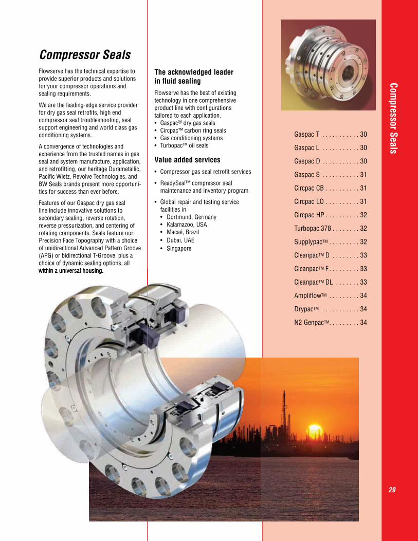
Compressor SealsFlowserve has the technical expertise to provide superior products and solutions for your compressor operations and sealing requirements.
We are the leading-edge service provider for dry gas seal retrofits, high end compressor seal troubleshooting, seal support engineering and world class gas conditioning systems.
A convergence of technologies and experience from the trusted names in gas seal and system manufacture, application, and retrofitting, our heritage Durametallic, Pacific Wietz, Revolve Technologies, and BW Seals brands present more opportuni-ties for success than ever before.
Features of our Gaspac dry gas seal line include innovative solutions to secondary sealing, reverse rotation, reverse pressurization, and centering of rotating components. Seals feature our Precision Face Topography with a choice of unidirectional Advanced Pattern Groove (APG) or bidirectional T-Groove, plus a choice of dynamic sealing options, all within a universal housing.
The acknowledged leader in fluid sealingFlowserve has the best of existing technology in one comprehensive product line with configurations tailored to each application. • Gaspac® dry gas seals • Circpac™ carbon ring seals • Gas conditioning systems • Turbopac™ oil seals
Value added services • Compressorgassealretrofitservices
• ReadySeal™compressorseal maintenance and inventory program
• Globalrepairandtestingservice facilities in • Dortmund,Germany • Kalamazoo,USA • Macaé,Brazil • Dubai,UAE • Singapore
Gaspac T . . . . . . . . . . . 30
Gaspac L . . . . . . . . . . . 30
Gaspac D . . . . . . . . . . . 30
Gaspac S . . . . . . . . . . . 31
Circpac CB . . . . . . . . . . 31
Circpac LO . . . . . . . . . . 31
CircpacHP . . . . . . . . . . 32
Turbopac 378 . . . . . . . . 32
SupplypacTM . . . . . . . . . 32
CleanpacTM D . . . . . . . . 33
CleanpacTM F . . . . . . . . . 33
CleanpacTM DL . . . . . . . 33
AmpliflowTM . . . . . . . . . 34
DrypacTM. . . . . . . . . . . . 34
N2 GenpacTM. . . . . . . . . 34
within a universal housing.

Compressor Seals
30
Gaspac TTandem compressor seals
Equipment Type• Compressors Operating ParametersPressure up to 425 bar (6160 psi)
Temperature -100 to 230°C (-150 to 450°F)
Speed 1 to 250 m/s (3 to 820 fps)
Shaft Sizes 40 to 360 mm (1.500 to 14.125 inch)
Features• Tandem arrangement cartridge seal
• Bothinboardandoutboardsealshave full product pressure capability
• Outboardsealnormallyoperatesunder low pressure. In the event of an inboard seal failure, the outboard seal acts as an installed spare
• Processgashascontrolledleakage across both sets of seal faces
• ChoicebetweenT-Grooveface geometry for bidirectional rotation or Advanced Pattern Groove for unidirectional rotation
•Sealfacesarenoncontactingfrom slow roll up to the highest speeds
•SpringenergizedO-ringprovideslow drag for excellent seal face tracking
•OptionalPTFEdynamicsealingelement extends the temperature range and chemical resistance
•Standardizedinboardandoutboard seal parts for easy interchangeability
•Higherpressuresandlargersizes available on request
Reference FSD113
Gaspac DDouble compressor seals
Equipment Type• Compressors Operating ParametersPressure up to 60 bar (870 psi)
Temperature -100 to 200°C (-150 to 400°F)
Speed 1 to 140 m/s (3 to 460 fps)
Shaft Sizes 40 to 360 mm (1.500 to 14.125 inch)
Features• Dual pressurized opposed arrangement seal configuration
• Inboard and outboard seals run at barrier pressure set higher than the process pressure
• For toxic and/or flammable process gases where zero process emissions are required
• For process gas contaminated with particles
• For very low pressure applications where a tandem seal can not be used
• Choice between T-Groove face geometry for bidirectional rotation or Advanced Pattern Groove for unidirec- tional rotation
• Seal faces are noncontacting from slow roll up to the highest speeds
• Spring energized O-ring provides low drag for excellent seal face tracking
• Optional PTFE dynamic sealing element extends the temperature range and chemical resistance
• Standardized inboard and outboard seal parts for easy interchangeability
• Higherpressuresandlargersizes available on request
Reference FSD113
Gaspac LTandem seal with interstage labyrinth
Equipment Type• Compressors Operating ParametersPressure up to 425 bar (6160 psi)
Temperature -100 to 230°C (-150 to 450°F)
Speed 1 to 250 m/s (3 to 820 fps)
Shaft Sizes 40 to 360 mm (1.500 to 14.125 inch)
Features• Interstagelabyrinthkeepsprocessgas from migrating to outboard seal faces
• Eliminate process leakage gas to atmosphere with interstage purge
• Both inboard and outboard seals have full product pressure capability
•Outboard seal acts as an installed spare with full pressure capability
• Choice between T-Groove face geometry for bidirectional rotation or Advanced Pattern Groove for unidirectional rotation
•Seal faces are noncontacting from slow roll up to the highest speeds
•Spring energized O-ring provides low drag for excellent seal face tracking
•Optional PTFE dynamic sealing element extends the temperature range and chemical resistance
•Standardized inboard and outboard seal parts for easy interchangeability
•Higherpressuresand larger sizes available on request
Reference FSD113
Compressor Seals
31
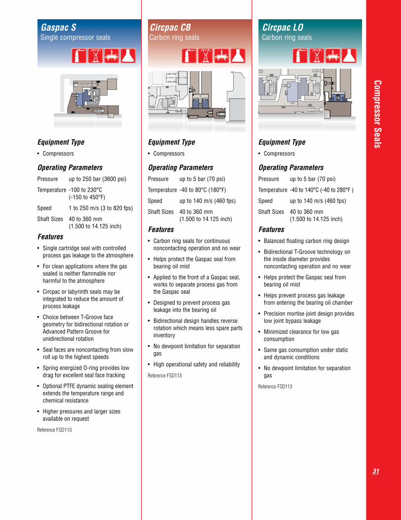
Gaspac SSingle compressor seals
Equipment Type• Compressors Operating ParametersPressure up to 250 bar (3600 psi)
Temperature -100 to 230°C (-150 to 450°F)
Speed 1 to 250 m/s (3 to 820 fps)
Shaft Sizes 40 to 360 mm (1.500 to 14.125 inch)
Features• Singlecartridgesealwithcontrolled process gas leakage to the atmosphere
• Forcleanapplicationswherethegas sealed is neither flammable nor harmful to the atmosphere
• Circpacorlabyrinthsealsmaybe integrated to reduce the amount of process leakage
• ChoicebetweenT-Grooveface geometry for bidirectional rotation or Advanced Pattern Groove for unidirectional rotation
• Sealfacesarenoncontactingfromslow roll up to the highest speeds
• SpringenergizedO-ringprovideslow drag for excellent seal face tracking
• OptionalPTFEdynamicsealingelement extends the temperature range and chemical resistance
• Higherpressuresand larger sizes available on request
Reference FSD113
Circpac CBCarbon ring seals
Equipment Type• Compressors Operating ParametersPressure up to 5 bar (70 psi)
Temperature -40 to 80°C (180°F)
Speed up to 140 m/s (460 fps)
Shaft Sizes 40 to 360 mm (1.500 to 14.125 inch)
Features• Carbonringsealsforcontinuous noncontacting operation and no wear
• HelpsprotecttheGaspacsealfrom bearing oil mist
• AppliedtothefrontofaGaspacseal, works to separate process gas from the Gaspac seal
• Designedtopreventprocessgas leakage into the bearing oil
• Bidirectionaldesignhandlesreverse rotation which means less spare parts inventory
• Nodewpointlimitationforseparation gas
• Highoperationalsafetyandreliability
Reference FSD113
Circpac LOCarbon ring seals
Equipment Type• Compressors Operating ParametersPressure up to 5 bar (70 psi)
Temperature -40 to 140°C (-40 to 280°F )
Speed up to 140 m/s (460 fps)
Shaft Sizes 40 to 360 mm (1.500 to 14.125 inch)
Features• Balancedfloatingcarbonringdesign
• BidirectionalT-Groovetechnologyon the inside diameter provides noncontacting operation and no wear
• HelpsprotecttheGaspacsealfrom bearing oil mist
• Helpspreventprocessgasleakage from entering the bearing oil chamber
• Precisionmortisejointdesignprovides low joint bypass leakage
• Minimizedclearanceforlowgas consumption
• Samegasconsumptionunderstatic and dynamic conditions
• Nodewpointlimitationforseparation gas
Reference FSD113

Compressor Seals
32
Turbopac 378Turbo compressor seals
Equipment Type• Compressors
Operating ParametersPressure up to 100 bar (1450 psi)
Temperature -40 to 180°C (360°F)
Speed up to 90 m/s (300 fps)
Shaft Sizes 40 to 260 mm (1.500 to 10.250 inch)
Features• Balancedsingleordual seal
• Bidirectionalsealfacetechnology
• Designedforoptimizedoperational safety and reliability for higher speed and pressure applications
• Non-rotatingspringassemblyfor higher rotational speed
• Reversepressurecapability
• Cartridgedesignavailableforeasy installation
• Solidstationaryface
• Optimizedheattransfer
• Handlesemergencyshutdowns
• Availableinfacetofacearrangement
Other ConfigurationsTurbopac 2100
• Dualpressurizedsealforhighpressure applications up to 100 m/s (330 fps) and 300 bar (4350 psi)
Reference FSD113
Supplypac TM
Dry gas seal support system
Equipment Type• Compressors
Operating ParametersPressure up to 413.6 bar (6000 psi)
Temperature up to 204°C (400°F)
Features• EliminatesNDErequiredwithwelded systems
• Enhancedsafetyoverweldedsystems
• Shorteneddeliverycyclesthrough reduction in engineering, manufactur- ing and assembly time
• Flexible,modulardesign,keyforoffshore installations with space limitations
• Accommodatesbolt-onsealgas conditioning equipment whether added at the factory or in the field
• Allowsforindividualcomponentpack- aging and shipping to accommodate field assembly
Design Specifications• MeetsAPI614designcriteriaandis ASME B31.3 certified
• UtilizesproprietaryFlowserveflanges
• Effectiveborecomparableto1inch XXS pipe
• Flowpathsarescalableforlowerpressure, larger bore, and higher flow rates
• Materials: 316/316L stainless steel, monel, and others as required
• Gaskets:FKM,FFKM,PTFE,RTJ, spiral wound
• Industrystandardmaterialcertification available for components
Reference FSD113
Circpac HPCarbon ring seals
Equipment Type• Compressors Operating ParametersPressure up to 10 bar (145 psi)
Temperature -40 to 180°C (350°F)
Speed up to 90 m/s (300 fps)
Shaft Sizes 25 to 280 mm (1.000 to 11.000 inch)
Features• Carbon ring seals for stand alone operation
• Costeffectivesealingsolutionforlow pressure applications where the very low leakage of a conventional gas seal is not required
• Anyringcombinationcanbearranged in a Circpac seal to meet specific application requirements
• Additionalfeaturessuchaslabyrinths, face seals, pressure sensing ports and purge/vent/drain ports are available
Reference FSD113

Compressor Seals
33
Cleanpac TM DLiquid removal system
Equipment Type• Compressors
Design SpecificationsType of filtration Bulk liquid removal
Bulk liquid Plate / mesh pad removal
Efficiency 10μ particles @ 99%
Maximum flow 622 ALM (22 ACFM) rate
Lower chamber 5 liter (1.3 gallon) liquid holding capacity
Maximum design 350 bar (5076 psi) pressure
Maximum design 204°C (400°F) temperature
Features• Largest single purpose liquid removal vessel in the Flowserve inventory
• Incorporatesdualstagetechnology to insure maximum efficiency
• Meshpadremoveslargeparticles (>10 µm) and coalesces fine mists and liquids that are entrained within the gas stream
Other ConfigurationsCleanpac DC
• Employs all of the liquid removal capabilities of the Cleanpac D in a highly compact design
Reference FSD113
Design Specifications
Cleanpac TM FPre-filter
Equipment Type• Compressors
Design SpecificationsType of filtration Coalescing
Bulk liquid Vane pack removal
Efficiency 0.3μ Absolute
Maximum flow 622 ALM (22 ACFM) rate
Lower chamber 3.5 liter (0.9 gallon) liquid holding capacity
Upper chamber 2.6 liter (0.68 gallon) liquid holding capacity
Maximum design 350 bar (5076 psi) pressure
Maximum design 204°C (400°F) temperature
Features• Dual stage liquid knockout and fine particulate filter
• Benefits of a pre-filter liquid removal system and a final coalescing filter in one complete package
• Largercoalescing element allows for extended operational periods between change-outs or accommodates extremely high levels of particulate contamination
Reference FSD113
Design Specifications
Cleanpac TM DLSingle and dual coalescing filters
Equipment Type• Compressors
Design SpecificationsType of filtration Coalescing
Efficiency 0.3μ Absolute
Maximum flow 368 ALM (13 ACFM) rate
Lower chamber 0.213 liter liquid holding (0.05 gallon) capacity
Maximum design 350 bar (5076 psi) pressure
Maximum design 204°C (400 °F) temperature Features• A general service coalescing filter assembly designed to protect dry gas seals and other sensitive equipment from particles and fine liquid mists
• The simple design is focused on the safety of continuous flow and ease of use
• Can be configured in single, dual arrangements (with or without transfer valve) and in a double block and bleed arrangement
•Withtheadditionofactuatedtransfer valves the versatility of the Cleanpac DL is expanded to include utilization in unmanned stations
• ThetypicalapplicationoftheCleanpac DL is a combination of the transfer valve and two single housings, creating an assembly that is reliable and effective
Reference FSD113

Compressor Seals
34
Equipment Type• Compressors Operating ParametersPressure up to 345 bar (5000 psi)
Temperature up to 200°C (400°F)
Design SpecificationsMaterials of Marine grade constructon aluminum or stainless steel
End connections NPT, flanged or butt weld
Booster drive Air, N2 or clean media process gas
Features
• Helps ensure that an adequate supply of clean, filtered gas is provided to the seals during periods of low differential across the compressor
• Canbeconfiguredasaportableunit, a stand alone panel or integrated with a Flowserve dry gas seal control panel or a Flowserve filter gas conditioning panel
Reference FSD113
Equipment Type
Ampliflow TM
Ensures adequate supply of clean, filtered gas
Equipment Type• Compressors Features• Reduce the potential of liquid formation between the seal faces by lowering the dew point of the gas and raising the temperature of the seal supply gas at least 20°C (36°F) above the dew point as recommended by API standards
• HelpsincreasetheMTBFofdrygas seals when the dew point of the gas is a potential issue
• Simplifiedinstallation,operationand maintenance
• Canbeintegratedwithanexisting gas seal control panel
Reference FSD113
Drypac TM
Gas dryer
Equipment Type• Compressors Features• Generates nitrogen gas from compressed air in hazardous conditions or remote locations
• Each unit provides dual parallel filtration for nitrogen flow without interruption
• Designed as an independent system and can also be integrated with the Flowserve Dry Gas Seal Panel or Flowserve CleanpacTM and DrypacTM gas conditioning system
•Nitrogenpuritiesbetween97%and99%
• Oxygenanalyzeravailable
• Monitoredfilterperformancewith differential pressure indicating transmitters and inlet/outlet pressure gauges
• Designedforeaseofmaintenance
• Stainlesssteelandaluminumdesigns
Reference FSD113
N2 Genpac TM
Nitrogen generatorDrypac TM

35
Slurry Seals
35
Flowserve offers a complete range of sealing products for all types of slurries in mining and ore processing, wastewater, flue gas desulphurization, and general dirty services. Our rugged and robust slurry seals are engineered to perform and built to last.
Whether you have a slurry liquid that requires economic value, standard application or extreme service seals, Flowserve is uniquely positioned to provide the following solutions:• Thebroadestperformancewindowfor
flushless applications
• NoflushrequireduptoMOH9slurryparticle hardness
• Solidscontentupto60%byweight
• Smoothgeometriesandnon-wettedsprings resist clogging
• Economicaldesignsforlowsolidsapplications
• Modularcomponentsthatpromotefield repair capability
• Engineeredassembliestofitcommonslurry pumps
• Knowledgeableandexperiencedslurry team to support installation, commissioning and unique job site applications
• Enhancesealoperationandextendplant reliability with accessories: Synthetic Lubrication Device (SLD), Quench Containment Device (QCD), and Erosion Protection Device (EPD)
Slurry Seals
SLC. . . . . . . . . . . . . . . . 36
SLM-6000 . . . . . . . . . . 36
SLM-6200 . . . . . . . . . . 36
RIS . . . . . . . . . . . . . . . . 37
Allpac . . . . . . . . . . . . . . 37
Synthetic Lubrication Device (SLD), Quench Containment Device (QCD), and Erosion Protection Device (EPD)
plant reliability with accessories: Synthetic Lubrication Device (SLD), Quench Containment Device (QCD), and Erosion Protection Device (EPD)
Slurry Seals
36
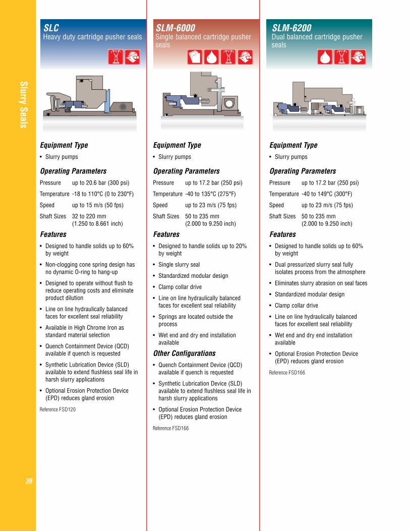
Equipment Type• Slurrypumps Operating ParametersPressure up to 20.6 bar (300 psi)
Temperature -18 to 110°C (0 to 230°F)
Speed up to 15 m/s (50 fps)
Shaft Sizes 32 to 220 mm (1.250 to 8.661 inch)
Features• Designedtohandlesolidsupto60% by weight
• Non-cloggingconespringdesignhas no dynamic O-ring to hang-up
• Designedtooperatewithoutflushto reduce operating costs and eliminate product dilution
• Lineonlinehydraulicallybalanced faces for excellent seal reliability
• AvailableinHighChromeIronas standard material selection
• QuenchContainmentDevice(QCD) available if quench is requested
• SyntheticLubricationDevice(SLD) available to extend flushless seal life in harsh slurry applications
• OptionalErosionProtectionDevice (EPD) reduces gland erosion
Reference FSD120
SLCHeavydutycartridgepusherseals
SLM-6000Single balanced cartridge pusher seals
SLM-6200Dual balanced cartridge pusher seals
Equipment Type• Slurrypumps Operating ParametersPressure up to 17.2 bar (250 psi)
Temperature -40 to 135°C (275°F)
Speed up to 23 m/s (75 fps)
Shaft Sizes 50 to 235 mm (2.000 to 9.250 inch)
Features• Designedtohandlesolidsupto20% by weight
• Singleslurryseal
• Standardizedmodulardesign
• Clampcollardrive
• Lineonlinehydraulicallybalanced faces for excellent seal reliability
• Springsarelocatedoutsidethe process
•Wetendanddryendinstallation available
Other Configurations
• QuenchContainmentDevice(QCD) available if quench is requested
• SyntheticLubricationDevice(SLD) available to extend flushless seal life in harsh slurry applications
• OptionalErosionProtectionDevice (EPD) reduces gland erosion
Reference FSD166
Equipment Type• Slurrypumps Operating ParametersPressure up to 17.2 bar (250 psi)
Temperature -40 to 149°C (300°F)
Speed up to 23 m/s (75 fps)
Shaft Sizes 50 to 235 mm (2.000 to 9.250 inch)
Features• Designedtohandlesolidsupto60% by weight
• Dualpressurizedslurrysealfully isolates process from the atmosphere
• Eliminatesslurryabrasiononsealfaces
• Standardizedmodulardesign
• Clampcollardrive
• Lineonlinehydraulicallybalanced faces for excellent seal reliability
•Wetendanddryendinstallation available
• OptionalErosionProtectionDevice (EPD) reduces gland erosion
Reference FSD166

Slurry Seals
37
RISRubber energized slurry seals
Equipment Type• ISOpumps Operating ParametersPressure up to 50 bar (725 psi)
Temperature -40 to 220°C (430°F)
Speed up to 50 m/s (164 fps)
Shaft Sizes 20 to 300 mm (0.750 to 11.750 inch)
Features• Springsoutsidetheproductavoid clogging
• Facesaremadefromsiliconcarbide
•Cleancomponentdesign
• Largeclearancesbetweensealand shaft sleeve
• Robustconstruction
•Metalfreedesignoptional
• Singleanddualsealcartridgedesigns available
• Singlespringandmultispringdesigns
Reference FSD129
AllpacGeneral duty pusher seals
Equipment Type• Slurrypumps Operating ParametersPressure up to 10.3 bar (150 psi)
Temperature -4 to 110°C (25 to 230°F)
Speed up to 11 m/s (36 fps)
Shaft Sizes 32 to 235 mm (1.250 to 9.250 inch)
Features• Designedtohandlesolidsupto50% by weight
• Non-cloggingelastomerspringdesign has no dynamic O-ring to hang up
• Externaladjustmentfeature compensates for seal face wear and pump misalignment
• Designedtooperatewithoutflushto reduce operating costs and eliminate product dilution
• Excellentperformanceexperiencein flue gas desulphurization (FGD)
Reference FSD151

Gas Barrier and Containment Seals
38
GF-200 . . . . . . . . . . . . . 39
GX-200. . . . . . . . . . . . . 39
GSL . . . . . . . . . . . . . . . 39
GSDH . . . . . . . . . . . . . . 40
GTSP . . . . . . . . . . . . . . 40
Running a liquid seal dry is commonly one of the quickest ways to shorten its life. Mechanical seals can, however, be designed to operate successfully without a liquid fluid film. Gas barrier seals have noncontacting seal faces that lift off during operation independent of what’s happening in the seal chamber; wet or dry. In the case of containment seals, the seal faces are designed to run dry under normal operation and also handle process liquid during upset events.
Gas barrier seals provide users the benefits of zero process emissions, no process contamination by liquid barrier fluid, a simplified support system, and low power consumption. Containment seals running behind wet seals provide proactive safety by directing process vapor leakage to a collection system, minimizing environmental emissions, and by having the ability to take over if the inboard seal fails.
Gas Barrier and Containment Seals
Gas seal technology pioneered in compressor seals is applicable to pumps and other rotating equipment by taking into account the same aerostatic and aerodynamic forces acting on the seal faces. Flowserve’s Precision Face Topography is the essential ingredient that establishes a strong and stable gas film. Unidirectional Advanced Pattern Groove (APG), bidirectional wavy face and hydropad designs are most common in pump seals. Both pusher and metal bellows seals employ the advantages of gas seal technology for a variety of services.
vapor leakage to a collection system, vapor leakage to a collection system, minimizing environmental emissions, and by having the ability to take over if the inboard seal fails.

Gas Barrier and Containment Seals
39
GF-200Dual noncontacting pusher seals
GX-200Dual noncontacting metal bellows seals
GSL Noncontacting bidirectional containment seals
Equipment Type• Generalpurposepumps Operating ParametersPressure up to 34.5 bar (500 psi)
Temperature -40 to 260°C (500°F)
Speed 1.3 to 25 m/s (4 to 82 fps)
Shaft Sizes 25.4 to 152 mm (1.000 to 6.000 inch)
Features• Dualpressurizedpusherseal
• Fitsinenlargedborepumps
• Usedinapplicationswhereno emissions of hazardous pumped product is tolerated
• AdvancedPatternGroove(APG) provides low speed lift-off, low gas leakage and no face contact, requiring about 25% less power to achieve the same flow and head than with a sealless pump
•SpringengergizedO-ringdesign provides consistent loading and low friction drag to reduce seal face hang-up
• Pressurizedwithaninertgasbarrier for lift-off eliminates contamination of pumped product by a buffer fluid
• Toleratesoff-designpumpoperation including vibration, cavitation and dry running
•Simpletoinstallandpressurize
Reference FSD137
Equipment Type• Generalpurposepumps Operating ParametersPressure up to 13.8 bar (200 psi)
Temperature -40 to 260°C (500°F)
Speed 2.5 to 35 m/s (8 to 115 fps)
Shaft Sizes 25.4 to 76.2 mm (1.000 to 3.000 inch)
Features• Dualpressurized,externallymounted metal bellows seals
• Usedinapplicationswhereno emissions of hazardous pumped product is tolerated
• FitsstandardorlargeboreASME and ISO pumps
•AdvancedPatternGrooveprovideslow speed lift-off, low gas leakage and no face contact
• AlloyC-276orAlloy718metalbellows provide superior seal face tracking responsiveness
• Solidsresistantfeaturesminimize contamination
• Pressurereversalproductcontainment during upset events
•Toleratesoff-designpumpoperation including vibration, cavitation and dry running
Reference FSD105
Equipment Type• API610pumpsandspecialty equipment Operating ParametersPressure up to 41.4 bar (600 psi)
Temperature -40 to 204°C (400°F)
Speed 1.5 to 30.5 m/s (5 to 100 fps)
Shaft Sizes 20.6 to 152 mm (0.813 to 6.000 inch)
Features• API682Arrangement2TypeA containment seal
• Dry-runningcontainmentsealfor flashing hydrocarbon services
• Noncontactingwavyfacedesign provides long-term reliable performance without the need for high maintenance support system
• Capableofnear-zeroemissionsduring normal conditions with use of a nitrogen sweep
•Capableoffullpressurewetbackup sealing in the event of a primary seal failure
• Availableforsinglesealapplicationsin gas services such as vertical sump pumps or on specialty equipment
Other ConfigurationsGSD
• Contacting containment seal designed for conversion of exisiting wet running outboard seals
Reference FSD143
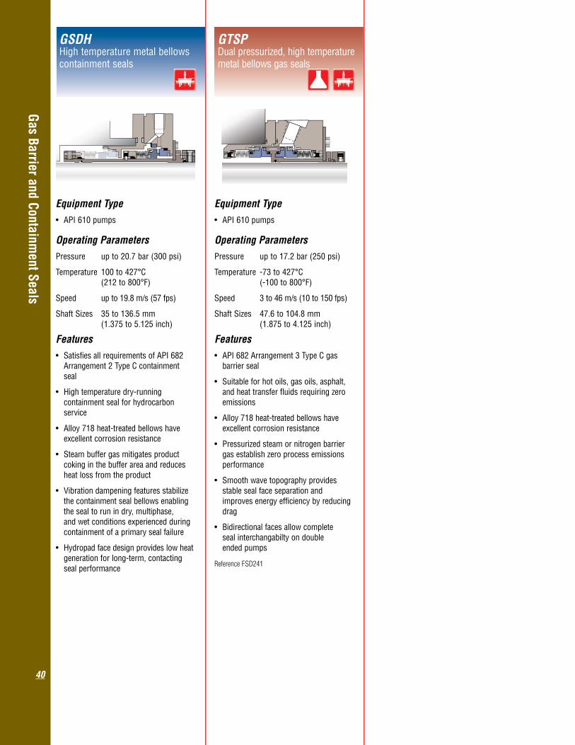
Gas Barrier and Containment Seals
40
GSDH Hightemperaturemetalbellowscontainment seals
GTSP Dual pressurized, high temperature metal bellows gas seals
Equipment Type• API610pumps Operating ParametersPressure up to 20.7 bar (300 psi)
Temperature 100 to 427°C (212 to 800°F)
Speed up to 19.8 m/s (57 fps)
Shaft Sizes 35 to 136.5 mm (1.375 to 5.125 inch)
Features• SatisfiesallrequirementsofAPI682 Arrangement 2 Type C containment seal
• Hightemperaturedry-running containment seal for hydrocarbon service
• Alloy718heat-treatedbellowshave excellent corrosion resistance
• Steambuffergasmitigatesproduct coking in the buffer area and reduces heat loss from the product
•Vibrationdampeningfeaturesstabilize the containment seal bellows enabling the seal to run in dry, multiphase, and wet conditions experienced during containment of a primary seal failure
• Hydropadfacedesignprovideslowheat generation for long-term, contacting seal performance
Equipment Type• API610pumps Operating ParametersPressure up to 17.2 bar (250 psi)
Temperature -73 to 427°C (-100 to 800°F)
Speed 3 to 46 m/s (10 to 150 fps)
Shaft Sizes 47.6 to 104.8 mm (1.875 to 4.125 inch)
Features• API682Arrangement3TypeCgas barrier seal
• Suitableforhotoils,gasoils,asphalt, and heat transfer fluids requiring zero emissions
• Alloy718heat-treatedbellowshave excellent corrosion resistance
• Pressurizedsteamornitrogenbarrier gas establish zero process emissions performance
•Smoothwavetopographyprovides stable seal face separation and improves energy efficiency by reducing drag
• Bidirectionalfacesallowcomplete seal interchangabilty on double ended pumps
Reference FSD241

OEM and Special Duty Seals
41
GTS . . . . . . . . . . . . . . . 42
GSS . . . . . . . . . . . . . . . 42
GSG . . . . . . . . . . . . . . . 42
PL-100 . . . . . . . . . . . . . 43
PSS III . . . . . . . . . . . . . 43
LS-300 . . . . . . . . . . . . . 43
Circpac MD. . . . . . . . . . 44
Pac-Seal . . . . . . . . . . . . 44
Original Equipment Manufacturers (OEM) are very important to Flowserve. We are committed to develop and supply designs for special equipment and special duty requirements.
Flowserve has developed special mechanical seals to handle the high speed and high pressure conditions for integrally geared API pumps and compressors with excellent performance and reliability. We also offer the GSG gearbox seal with a proven track record for increasing reliability on this type of equipment.
The LS-300 seal is another OEM design suited for low speed high viscosity positive displacement pumps. The PSS III seal is used when assembly of the equipment is difficult and a split seal offers significant benefits. PL-100/200 non-metallic seals are especially suited for non-metallic pumps.
In addition, the Pac-Seal range of single spring seals is available in a wide range of designs in accordance with common industry standards or according to OEM standards. Complete new custom designs can also be developed.
OEM & Special Duty Seals
LS-300LS-300
Circpac MD
Pac-Seal
LS-300
Circpac MD
Pac-Seal

OEM and Special Duty Seals
42
GTSMetal bellows seals for steam turbines
GSSGas lubricated wavy face non-contacting pusher seals
GSGHighspeedgearboxseals
Equipment Type• Steamturbines Operating ParametersPressure up to 20.7 bar (300 psi)
Temperature 100 to 343°C (212 to 650°F)
Speed 3 to 46 m/s (10 to 150 fps)
Shaft Sizes 54 to 111.1 mm (2.125 to 4.375 inch)
Features• Replacecarbonringsonsteamturbines to significantly reduce steam leakage and improve safety
• Thinfilmwavyfacetechnologyfornon- contacting operation on steam
• Thewavyfacesmoothsurfaceisnon- clogging and able to recover from upset conditions
•Alloy718bellowshaveexcellent corrosion resistance and tolerance to high temperatures
• Internalorexternalarrangement
• Detachabledesignforvariousdifferent turbines
• Designedtohandleslowrolloperation
Reference FSD107
Equipment Type• Highspeed,integrallygearedpumps and compressors Operating ParametersPressure up to 86.2 bar (1250 psi)
Temperature -62 to 204°C (-80 to 400°F)
Speed 1500 to 36,000 rpm
Shaft Sizes 38.1 mm (1.500 inch)
Features• Precisionfacetopographycreatesseal face liftoff to eliminate wear
• Noncontactingwavyfacegasseal design produces near zero power consumptions
• Configurableasasingleseal,adual seal, and as a dry running containment seal
• Inapressurizedarrangement,capable of zero emissions in hydrocarbon applications
• Specificallydesignedforhighspeed, integrally geared equipment
Other Configurations
GLS
• Liquidservicedesignwithcontacting seal faces
• Configurableasasingleseal,adual seal, and with a GSS seal as a containment seal
Reference FSD102
Equipment Type• Highspeed,integrallygearedpumps and compressors Operating ParametersPressure up to 17.2 bar (250 psi)
Temperature -40 to 204°C (400°F)
Speed 1500 to 36,000 rpm
Shaft Sizes 38.1 mm (1.500 inch)
Features• InnovativeHydrodynamicSurface Tension(HST)facetopography creates near zero leakage performance
• Designedforhighspeed,oil-flooded gearbox applications
• Proprietarylasermachinedwavyface enables high speed operation
• Directreplacementforexistingseals without equipment modification
• Sealfacematerialssuitablefor frequent starts and stops
Reference FSD102

OEM and Special Duty Seals
43
PL-100Non-metallic single seals for highly corrosive services
PSS IIISplit single pusher seals
LS-300Cartridge, multiple dynamic lip seals
Equipment Type• Pumps,mixers,agitators Operating ParametersPressure vacuum to 31 bar (450 psi)
Temperature -18 to 121°C (0 to 250°F)
Speed up to 12.7 m/s (42 fps)
Shaft Sizes 38.1 to 152.4 mm (1.500 to 6.000 inch)
Features• Semi-cartridgesplitseal
• Usedinnon-hazardousliquidservices in paper mills, waste water treatment facilities, soda ash processing and chemical plants
• Easytoinstallandrepair.Noneedto completely dismantle the pump
•Non-wettedspringsandpinseliminate clogging and seal face hang-up
• Sealfacesarepindrivenproviding positive seal face torque in higher viscosity services
• Positivedriverotorisheldfirmlyin place by set screws to accommodate higher pressures, torque and thrust loads
Reference FSD217
Equipment Type• Positivedisplacement,gear,and progressive cavity pumps Operating ParametersPressure up to 10.3 bar (150 psi)
Temperature -53 to 149°C (-65 to 300°F)
Speed up to 3.5 m/s (12 fps)
Shaft Sizes 19.1 to 76.2 mm (0.750 to 3.000 inch)
Features• Presetcartridgedesign
• Usedinthick,highlyviscous,and polymerizing fluids
• Standardviscosityrange: 80 to 12,000 cP (400 to 60,000 SSU)
• Designedtorundrywithouttheneed for an external flush or lubricating barrier fluid
•Triplelipdesigneffectivelysealsprocess from atmosphere
• Easytoinstallandeasytorepairinthe field
Reference FSD117
Equipment Type• Non-metallicorhighalloyASMEand ISO pumps Operating ParametersPressure vacuum to 10.3 bar (150 psi)
Temperature -18 to 150°C (0 to 300°F)
Speed up to23 m/s (60 fps)
Shaft Sizes 35 to 53 mm (1.375 to 2.750 inch)
Features• Nonmetallicwettedcomponentsprovide superior chemical resistance
• SpecialcarbonfiberreinforcedPTFE sleeve provides excellent mechanical properties to maintain overall seal integrity
• Affordablealternativetohighalloymetal seals
•Externalflushisnotrequired
Other ConfigurationsPL-200
Dual non-metallic seal provides zero • process emissions when pressurized
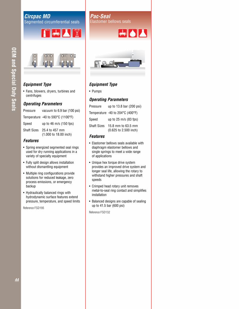
OEM and Special Duty Seals
44
Circpac MDSegmented circumferential seals
Pac-SealElastomer bellows seals
Equipment Type• Pumps Operating ParametersPressure up to 13.8 bar (200 psi)
Temperature -40 to 204°C (400°F)
Speed up to 25 m/s (83 fps)
Shaft Sizes 15.8 mm to 63.5 mm (0.625 to 2.500 inch)
Features• Elastomerbellowssealsavailablewith diaphragm elastomer bellows and single springs to meet a wide range of applications
• Uniquehextorquedrivesystem provides an improved drive system and longer seal life, allowing the rotary to withstand higher pressures and shaft speeds
• Crimpedheadrotaryunitremoves metal-to-seal ring contact and simplifies installation
• Balanceddesignsarecapableofsealing up to 41.5 bar (600 psi)
Reference FSD132
Equipment Type• Fans,blowers,dryers,turbinesand centrifuges Operating ParametersPressure vacuum to 6.9 bar (100 psi)
Temperature -40 to 593°C (1100°F)
Speed up to 46 m/s (150 fps)
Shaft Sizes 25.4 to 457 mm (1.000 to 18.00 inch)
Features• Springenergizedsegmentedsealrings used for dry running applications in a variety of specialty equipment
• Fullysplitdesignallowsinstallation without dismantling equipment
• Multipleringconfigurationsprovide solutions for reduced leakage, zero process emissions, or emergency backup
•Hydraulicallybalancedringswith hydrodynamic surface features extend pressure, temperature, and speed limits
Reference FSD195

Seal Support Systems
45
Fluid control over the sealing environment is very important to achieve effective and dependable sealing performance. Seal support systems are used to create that favorable environment around the mechanical seal. The appropriate selection of a seal support system will deliver years of reliable service and operating cost savings.
Seal Support Systems
Single seals running in hot environments or with little vapor pressure margin may require extra cooling to remove seal face heat and avoid product vaporization between the seal faces.
Pressurized and unpressurized dual seals require a barrier fluid at the correct pressure, flow, temperature and level to ensure proper functioning of the seals. This requires reservoirs, Plan 53B, Plan 53C systems and pressurizers. Gas barrier seals need gas supply panels for reliable performance.
Flowserve employs a specialized engineering team with years of experience and knowledge designing and selecting seal support systems to suit specific applications, specifications, and unique customer requirements. With a full range of products that meet ASME, API, PED, ISO, and NR13 design criteria, Flowserve addresses the global needs of the oil and gas, petrochemical, chemical, power, pharmaceutical, pulp and paper, and general industries.
W8 Buffer/Barrier . . . . . . . . 46Fluid Reservoirs
Buffer/Barrier . . . . . . . . . . . 46Fluid Reservoirs
Barrier Systems. . . . . . . . . . 47
Piston Transmitters . . . . . . . 47
Buffer/Barrier Gas Panels. . . 47
682 Seal Coolers .. . . . . . . . 48
LD 682 Seal Coolers. . . . . . .48
NX Seal Coolers. . . . . . . . . . 48
Airfin Seal Coolers . . . . . . . 49
Circulators . . . . . . . . . . . . . .49
Fill Cart . . . . . . . . . . . . . . . . 49
This requires reservoirs, Plan 53B, Plan 53C systems and pressurizers. Gas barrier seals need gas supply panels for reliable performance.
Flowserve employs a specialized engineering team with years of experience and knowledge designing and selecting seal support systems to suit specific applications, specifications, and unique customer requirements. With a full range of products that meet ASME, API, PED, ISO, and NR13 design criteria, Flowserve addresses the global needs of the oil and gas, petrochemical, chemical, power, pharmaceutical, pulp and paper, and general industries.

Seal Support Systems
46
W8 Buffer/Barrier Fluid Reservoirs ASME (ANSI) general duty
Buffer/Barrier Fluid Reservoirs API general duty, API 682
Buffer/Barrier Fluid Reservoirs ISO general duty
Operating ParametersPressure up to 11 bar (160 psi)
Temperature up to 65°C (150°F)
Volume 11.4 liter (3 gallon)
Features• Meetsthedesigncriteria Section VIII, ASME B31.3, PED
• Plan52and53Aconfigurations
• Economicallightdutyreservoirfor general service applications
•Instrumentationoneachreservoiris according to local standards and can be adapted to suit application and customer requirements
•304and316stainlesssteel construction
• Connectionsare0.500inchor0.750 inch NPT
• Coolingcoilisoptional
• Industrystandardmaterialcertification available for components
• FortheEuropeanmarket,asimilar ASME code design exists with 10 bar design pressure at 16 liter total volume
Other ConfigurationsCPM • 2.6liter(2gallon)capacityandcomes in 304 stainless steel
W2 ASME (ANSI 400)
• 7.6and15.1liter(2and4gallon) capacity for pressure up to 27.6 bar (400 psi)
Reference FSD239
Operating ParametersPressure up to 82.3 bar (1200 psi)
Temperature up to 148°C (300°F)
Volume 20 liter (5 gallon) Features• MeetsthedesigncriteriaofAPI682, ASME Section VIII, ASME B31.3, PED
• Plan52and53Aconfigurations
• Construction:Threaded,socketwelded, or butt welded
•Awiderangeofinstrumentationcanbe selected according to local standards and can be adapted to suit application and customer requirements
•316/316Lstainlesssteelconstruction
• Connectionsare0.750inchNPTor flange
• Optionalcleanablecoolingcoil
• Industrystandardmaterialcertification available for components
• Otherdesigncodesareavailableon request
Operating ParametersPressure up to 32 bar (464 psi) on 3 liter (0.8 gallon) and 6 liter (1.6 gallon)
up to 20 bar (290 psi) on 10 liter (2.5 gallon)
Temperature up to 65°C (150°F)
Volume 3 liter (0.8 gallon) 6 liter (1.6 gallon) 10 liter (2.5 gallon)
Features• SatisfiesTRDdesigncoderequirements
• Plan52and53Aconfigurations
•Instrumentationoneachreservoiristo German standards and can be adapted to suit application and customer requirements
• ConnectionsareG0.500
•Optionalhandpumprefillsreservoir under pressure

Seal Support Systems
47
Buffer/Barrier Gas Panels Plan 72/74
Barrier Systems Plan 53B
Operating ParametersPressure up to 82.3 bar (1200 psi)
Temperature up to 148°C (300°F)
Volume from 20 liter (5 gallon) up to 50 liter (13 gallon)
Features• Designcontainseitherfinnedpipeair cooling, a forced draft air cooling, or a water cooler to dissipate seal or pump heat
• MeetsthedesigncriteriaofAPI682, ASME Section VIII, ASME B31.3, PED
• Threaded,socketwelded,orbuttwelded piping
•Carbonsteeland316 / 316Lstainless steel construction
•Awiderangeofinstrumentationcanbe selected according to local standards and adapted to suit application and customer requirements
• Eachsealcanbeindividuallymonitored
• Variousaccumulatorsizesavailableto satisfy various operating conditions
Piston Transmitters Plan 53C
Operating ParametersPressure up to 75.8 bar (1100 psi)
Temperature up to 148°C (300°F)
Volume up to 11.4 liter (3 gallon)
Features• Apistontransmitterisapressure multiplier that generates barrier pressure for dual pressurized liquid seals based on the product pressure
• Usedwherethepressureinthepump fluctuates or the inboard seal pressure differential must be limited
• Pressuremultiplieroptions: 1:1.1, 1:1.15, and 1:1.2
•Bestusedforpressuresabove 3.5 bar (50 psi)
• Canbeprovidedwithacoolingcoil, external heat exchanger, instrumentation, and refill pump
• Standards:ASMEorPED
Operating ParametersPressure up to 34.4 bar (500 psi)
Temperature up to 93°C (200°F)
Flow upto14.2lpm(30SCFH)
Features• Buffer/Barriergaspanelscombineflow monitoring and control elements in a self-contained, easy to use unit
•Usedforunpressurizedandpressurized Flowserve gas seals
• Bufferpanelsprovideunpressurized dual seals with a gaseous quench to flush inner seal leakage to a collection system
• Barrierpanelsprovidedualsealswith gaseous barrier pressure set higher than the process pressure. This results in a small amount of gas leakage into the process and zero process leaking to atmosphere
• MeetsthedesigncriteriaofAPI682, ASME B31.3, PED
• Flowserveoffersotherconfigurationsof control systems ranging from simple standard to complex custom designs
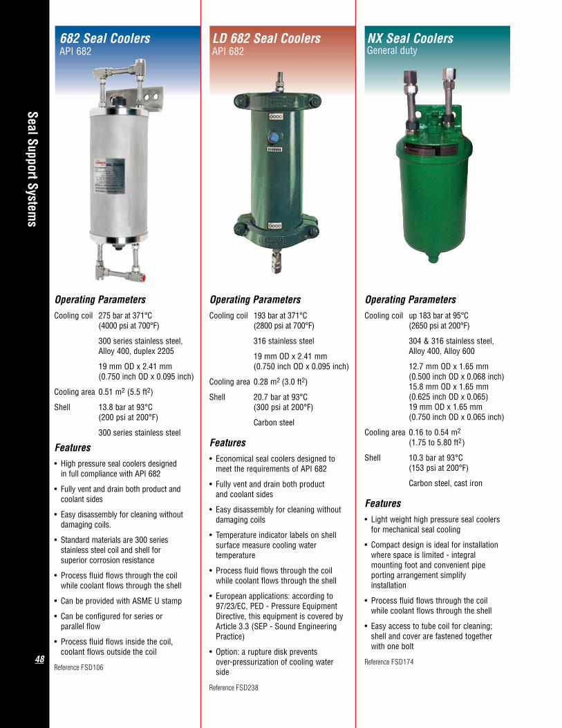
Seal Support Systems
48
NX Seal Coolers General duty
LD 682 Seal Coolers API 682
682 Seal Coolers API 682
Operating ParametersCooling coil 275 bar at 371°C (4000 psi at 700°F)
300 series stainless steel, Alloy 400, duplex 2205
19 mm OD x 2.41 mm (0.750 inch OD x 0.095 inch)
Cooling area 0.51 m2 (5.5 ft2)
Shell 13.8 bar at 93°C (200 psi at 200°F)
300 series stainless steel
Features• Highpressuresealcoolersdesigned in full compliance with API 682
• Fullyventanddrainbothproductand coolant sides
• Easydisassemblyforcleaningwithout damaging coils.
•Standardmaterialsare300series stainless steel coil and shell for superior corrosion resistance
• Processfluidflowsthroughthecoil while coolant flows through the shell
• CanbeprovidedwithASMEUstamp
• Canbeconfiguredforseriesor parallel flow
• Processfluidflowsinsidethecoil, coolant flows outside the coil
Reference FSD106
Operating ParametersCooling coil 193 bar at 371°C (2800 psi at 700°F)
316 stainless steel
19 mm OD x 2.41 mm (0.750 inch OD x 0.095 inch)
Cooling area 0.28 m2 (3.0 ft2)
Shell 20.7 bar at 93°C (300 psi at 200°F)
Carbon steel
Features• Economicalsealcoolersdesignedto meet the requirements of API 682
• Fullyventanddrainbothproduct and coolant sides
• Easydisassemblyforcleaningwithout damaging coils
• Temperatureindicatorlabelsonshell surface measure cooling water temperature
• Processfluidflowsthroughthecoil while coolant flows through the shell
• Europeanapplications:accordingto 97/23/EC, PED - Pressure Equipment Directive, this equipment is covered by Article 3.3 (SEP - Sound Engineering Practice)
• Option:arupturediskprevents over-pressurization of cooling water side
Reference FSD238
Operating ParametersCooling coil up 183 bar at 95°C (2650 psi at 200°F)
304 & 316 stainless steel, Alloy 400, Alloy 600
12.7 mm OD x 1.65 mm (0.500 inch OD x 0.068 inch) 15.8 mm OD x 1.65 mm (0.625 inch OD x 0.065) 19 mm OD x 1.65 mm (0.750 inch OD x 0.065 inch)
Cooling area 0.16 to 0.54 m2 (1.75 to 5.80 ft2)
Shell 10.3 bar at 93°C (153 psi at 200°F)
Carbon steel, cast iron
Features• Lightweighthighpressuresealcoolers for mechanical seal cooling
• Compactdesignisidealforinstallation where space is limited - integral mounting foot and convenient pipe porting arrangement simplify installation
• Processfluidflowsthroughthecoil while coolant flows through the shell
• Easyaccesstotubecoilforcleaning; shell and cover are fastened together with one bolt
Reference FSD174

Seal Support Systems
49
Fill Cart Reservoir refill
Airfin Seal Coolers Natural and forced draft
Operating ParametersCooling coil up 141 bar at 95°C (2050 psi at 200°F)
304 stainless steel
15.8 mm OD x 1.65 mm (0.625 inch OD x 0.065 inch)
Cooling area 2.5 m2 (26.8 ft2)
Features• Aircooledsealcoolersreduce temperatures surrounding the mechanical seal without using cooling water
• AirfinSealCoolersoffersubstantial savings in flush water purchase and treatment, and they are less susceptible for fouling and require less piping
• Standardcoolertypesinclude625NC with natural convection and 625 FC with forced air using an electric or pneumatic motor
• Forcedaircoolermotorsareexplosion proof Class 1, Gr D, Div 1, 1/3 hp as standard
• Processfluidflowsthroughthecoil while air flows across the coil's finned exterior
• Finmaterialsincludecarbonsteel, aluminum and stainless steel options
Reference FSD197
Circulators Plan 54
Operating ParametersFlow 3.8 or 15 l/min (1 or 4 gpm)
Pressure 27.6 bar (400 psi)
Temperature 4.4 to -60°C (40 to 140°F)
Volume 95 liter (25 gallon)
Features• Plan54circulatorsaredesignedto provide clean barrier fluid at a controlled flow rate, pressure and temperature
• Flowiscreatedbyapositive displacement pump and pressure is controlled by valves
• Systemcleanlinessismaintainedusing one or more high quality full flow liquid filters to ensure the fluid is clean and free of contamination
• Plan54systemscanbeinstrumented to support multiple seals or pumps
• Awiderangeofinstrumentationcanbe selected according to local standards and adapted to suit application and customer requirements
• Coolingcoilinsidethereservoiris optional
Reference FSD122
Operating ParametersPressure 103 bar (1500 psi)
Volume 76 liter (20 gallon)
Features• Refillyoursupplytanksinoperation without pump downtime or venting unwanted gases to atmosphere
• Capableofinjectingnewbarrierfluid into the supply tank at pressures up to 103 bar (1500 psi)
• Ruggedconstruction,easy-to- maneuver 76 liter (20 gallon) reservoir with hand pump mounted on a cart with pneumatic tires
•Availablewithcolor-codedquick disconnects to prevent refilling with the incorrect barrier fluid

Accessories
50
AccessoriesFocused on the primary goals of long term reliability, safety, and minimal maintenance, accessories for mechani-cal seals and associated equipment help customers achieve these objec-tives. Cyclone separators and magnetic separators, when added to a piping plan remove entrained particulate from the coolant stream, thus protecting seals and other system components. Seal Gard flow controllers provide just the right amount of flush flow to keep seals running cool and clean.
Bearing Gard II . . . . . . . 51
BGM . . . . . . . . . . . . . . . 51
Seal Gard I and II . . . . . 51
Magnetic Separator . . . 52
Cyclone Separator . . . . 52
SLD . . . . . . . . . . . . . . . 52
As a valuable ancillary sealing product, labyrinth and magnetic bearing isolators installed in pump bearing frames and electric motors keep contamination away from the bearings optimizing operating conditions for greater longevity and ultimately contributing to less downtime for the complete drive train system.
Presented in this catalog is a sampling of available accessories offered by Flowserve. A collection of other supporting products such as Duraclear synthetic lubricants and barrier fluids, various throat bushings, solids excluder devices, flow management orifices, gasket materials and instrumenta-tion complete the package necessary for well designed seal support systems. Reaching back to our heritage, we also supply an array of compression packing materials and related tools.
orifices, gasket materials and instrumenta-tion complete the package necessary for well designed seal support systems. Reaching back to our heritage, we also supply an array of compression packing materials and related tools.

Accessories
51
Bearing Gard IIBearing isolators
Equipment Type• Pumps,electricmotors,gearboxes, other rotating equipment
Operating ParametersShaft Sizes 15.9 to 254 mm (0.625 to 10.000) inch
Features• Installsonbearingframesusedinoil& gas, chemical, mining, pulp & paper, power and general industries
• Closetolerancelabyrinthdesignlocks out moisture, grit and dust, extending bearing life and increasing the MTBR of rotating equipment
• Easytoinstallonepiececartridge unit. On most equipment, requires no modification
•Samedayshipmentofpopularsizes
• Laststhelifeoftheequipment
• Fitsexistinglipsealcavities
Reference FSD124
BGMMagnetic bearing isolators
Equipment Type• Pumps,electricmotors,gearboxes, other rotating equipment
Operating ParametersShaft Sizes 15.9 to 152 mm (0.625 to 6.000) inch
Features• Installsonbearingframesusedinoil& gas, chemical, mining, pulp & paper, power and general industries
• Rareearthmagnetskeeptheseal faces closed
• Sealsoffthebearinghousing completely from the effects of high humidity, temperature transients, heat and dust environments
• Easytoinstalldesign
• Coaxialfacedesignprovidesthelongest possible seal life
•Lastsupto25timeslongerthanlip seals
Reference FSD149
Seal Gard I and IISeal chamber and stuffing box protection
Equipment Type• Pumps
Operating ParametersFlow up to 2.6 l/min (40 gph)
Presssure up to 20.7 bar (300 psi)
up to 8.6 bar (125 psi) 140°C (300°F)
Temperature 0 to 140°C (32 to 300°F)
Connections 0.250 inch NPT
Features• Tough,unitizedconstruction
• SealGardIcontrolsflowsatlowflush rates in a Plan 32 system
• SealGardIIprovidesdependableflow control to support dual seals while saving water costs and reducing seal water usage
• Goodforpaperstocksealingsystems with Flowserve split seals and split flow reducers
• Thevertical,taperedacrylicflowtube resists fouling
• Easytoreadpressuregaugeisvibration resistant and glycerine filled
•Intheupseteventoflostsealwater pressure, the standard check valve stops the back-up of product and prevents contamination of the water supply
Reference FSD154

Accessories
52
Magnetic Separator Iron particle trap
Cyclone SeparatorSolid particle excluder
SLDSynthetic lubrication device
Operating ParametersFlow up to 15 l/min (4 gpm)
Pressure up to 103.4 bar (1500 psi)
Temperature up to 204°C (400°F)
Connections 0.500 inch NPT, MS-6670-DJ
0.750 inch NPT, MS-0750-DJ
Features• DesignedforPlan23mechanicalseal injection flow and similar closed loop control lines
• Createsamagneticfieldthatseparates and holds iron oxide particles from the process liquid
• Preventironparticlesfromcausing abrasion or damage
Reference FSD173
Operating ParametersFlow Clean flow output from 3.4 - 30.3 l/min (0.9 - 8 gpm)
Pressure up to 138 bar (2000 psi) at 330°C (650°F)
up to 93 bar (1350 psi) at 455°C (850°F)
Temperature up to 455°C (850°F)
Connections 0.500 to 0.750 inch NPT or socket weld
Features• Offeredinthreedifferentsizesbased on flow rate and pressure
• Cycloneseparatorsaredesignedto efficiently remove sand, pipe scale and other abrasive particles from Plan 31 injection flow to mechanical seals
• Separationisaccomplishedby centrifugal effects generated by differential pressure across the cyclone
• Whenproperlyconfigured,provides up to 99% separation efficiency
Reference FSD173
Operating ParametersProcess up to 80°C (175°F) temperature
Ambient -20 to 55°C temperature (-4 to 130°F)
Features• Unitized system does not require air, electricity, or external water
• Idealforsingleliquidsealswith two hard faces and a Quench Containment Device (QCD)
• Singlepointlubricatorallowseach seal quench cavity to be satisfied independent of other equipment
• Usedwhennoquenchwateris available, ideal for frequent automatic start/stop sequences and installations at remote field locations
• DS-920-OGDuraClearlubricantresists breakdown when mixed with pumpage, water or containments; optional DS-460-F lubricant is approved by USDA for incidental food contact
• Customizeddispensingrateforeach application; provides precise lubrication for varying operating condition
Reference FSD148

53
Basic design and operationMechanical seals provide the most effective means of sealing rotating equipment, handling process liquids and gases in modern rotating equipment such as cen-trifugal pumps, compressors, mixers, and reactors. The ability to effectively limit or eliminate process fluid from leaking to the environment has made the mechani-cal seal the default sealing device for modern industry.
While all seal designs share some common character-istics, the success of an application depends on the proper selection of the seal model, design options, materials, arrangements, and piping plans. Flowserve engineers can help provide guidance for the most appropriate seal and sealing system selection for each application.
A mechanical seal in its simplest terms creates a controlled fluid film between a rotating seal face (or rotor) and a stationary seal face (or stator). These seal faces are attached to the rotating shaft and the stationary seal chamber through adaptive hardware such as sleeves and glands. These and other seal components work together to allow the seal to operate on a very thin fluid film between the rotating and stationary seal faces. The thickness of the fluid film is engineered to minimize seal emissions and face wear while maximizing seal life and reliability.
rotating facestationary face
gland
gland port
set screw
drive pins
gland gasket
stationary face o-rings
sleeve o-ring
sleeve
spring
rotating face o-ring
setting device
collar
throttle bushing

54
Mechanical seals can be designed to operate on liquid, gas, or mixed phase process fluids. In contacting liquid seals, the fluid film provides hydrostatic support as well as lubrication and cooling between the seal faces. The fluid film thickness is typically on the same order of magnitude as the roughness of the seal faces; approxi-mately 0.5 micron or 20 microinches. This results in a light contact between the asperities of the seal faces allowing for a low coefficient of friction and low wear while minimizing seal emissions. Tribologically, opera-tion in this mixed lubrication regime requires precise control of seal face topography, hydraulic loading, face deformations, and material properties. Flowserve has optimized these design factors to create the optimum seal performance.optimized these design factors to create the optimum
Magnified approximately 2000 times, these three dimensional images illustrate surface roughness on silicon carbide seal faces. The grooves on the lower image are the result of light asperity contact with a carbon graphite mating face.
High resolution, cross sectional trace of seal face roughness. The top trace is a new face while the bottom trace illustrates the results of light asperity contact.
Seal faces are also designed to operate with a gas or vapor film. This expands the ability of a mechanical seal to provide sealing into a wider range of equipment and more demanding operating window. Dry running seal faces are typically designed to operate in a noncontacting mode.Highlyengineeredfeaturesonthesealfaces are designed to create a hydrodynamic lift which effectively separates the seal faces during operation. This results in very low power requirements and allows for operation at higher speeds and pressures.

55
Design and modeling capabilitiesFlowserve has developed some of the most advanced seal modeling and design capabilities in the world. Analytical techniques including finite element analysis (FEA) and specialized multi-physics models are specifi-cally tailored for the unique characteristics of mechani-cal seals. The development of new microfeatures and face topography designs have only been possible due to advanced seal modeling capabilities. Seal models are continuously verified and refined through active research and development programs. Better modeling accuracy in the office establishes safer, more reliable mechanical seals in the field.
flat face
hydropads
APG
T-grooves
waves
HST
Precision face topographyAdvanced design and manufacturing capabilities have further expanded the ability of mechanical seals to operate in more demanding environments than ever before. The control of the seal face topography and innovative design of microfeatures have redefined the way mechanical seals operate. The sealing interface is no longer restricted to only flat faces. Face features can be designed to enhance the fluid film, create lift, reduce friction, minimize emissions, and reduce wear. These features can only be created with sophisticated manufacturing techniques which are capable of providing the accuracy and precision required for these microfeatures. Flowserve has pioneered the use of these techniques in mechanical seal design and manufacturing.

56
Seal typeSeals are commonly categorized as “pusher seal” and “bellows seal" based on the type of mechnaical loading used. A pusher seal consists of two seal faces where the flexible seal face utilizes a dynamic gasket to allow for axial motion and is loaded by mechanical springs. This is the most common seal design. Pusher seals can be designed for application conditions ranging from simple design for low duties to highly engineered complex designs for very high pressures and speeds.
A bellows seal utilizes a flexible bellows element to allow for axial motion. The bellows element itself is also commonly used to provide mechanical loading for the seal faces. One of the most common bellows seal designs uses an edge welded metal bellows. These are constructed from corrosion resistant alloys which allow their use in harsh chemical environments. Special designs with flexible graphite gasketing are designed to operate at extreme temperatures. By eliminating the dynamic gasket, bellows seals can be more tolerant of solids or process contamination. Elastomeric bellows designs are also commonly used in lower duty services.
Cartridge and component sealsMechanical seals have historically been offered as both component seals and cartridge seals. A component seal consists of basic seal parts which must be installed into the pump as individual components. This requires significant skills and care to ensure proper installation. A cartridge seal is packaged so that all components are preassembled and can be installed into the pump as a complete assembly. This ensures that all the components are correctly installed and not damaged during installation. Most mechanical seals supplied to industrial users are provided as cartridge seals.
Mechanical seals are available in a wide range of designs and capabilities. This is necessary to provide solutions for the similarly wide range of pump and equipment designs, process conditions, and operating requirements demanded by industry.
Design optionsThe selection of the appropriate seal design, design features, seal arrangement and piping plan is critical to achieving the seal performance required by the end user. Seal designs can be cat-egorized by a number of different design features.
set screw pin
spring
pin
dynamic o-ring
Component pusher seal
o-ring
Component metal bellows seal
Cartridge pusher seal
sleeve
rotating face
stationary face
rotating face
stationary face
o-ringset screw shaft o-ring
bellows
setting device remove during installation

57
Rotating vs stationary flexible elementThe flexible element (springs or bellows) can be designed so they rotate with the seal sleeve or are stationary with the seal gland. Rotating flexible elements are the most common design and provide for small radial cross sections and self-cleaning performance. Stationary flexible elements can tolerate higher equipment misalignments and can operate at higher speeds. Most sealing applications can be satisfactorily sealed with either design.
Single and dual sealsMost mechanical seal installations have one set of seal faces in the assembly. There are however applications where it is beneficial to have multiple seals to provide reduced emissions or sealing redundancy. These options are described as seal arrangements.
Arrangement 1 seals are single seals which contain one set of seal faces. This provides for a simple installation although all leakage goes to the atmospheric side of the seal. Arrangement 2 seals have two sets of seal faces where the cavity between the two seals is maintained at a lower pressure than the seal chamber pressure.
Any leakage past the primary seal is captured in this cavity which minimizes process exposure to the environment. This dual seal arrangement also provides sealing redundancy if one seal fails. Arrangement 3 seals have two sets of seal faces where the cavity between the two seals is maintained at a pressure greater than the seal chamber pressure. This has the benefit of elimi-nating any process leakage to the environment and making the seal less dependent on process conditions. All seal arrangements are commonly used in industry.
Arrangement 1 - Single seal Arrangement 2 and 3 - Dual seal
seal chamber
cavity between sealsArrangement 2 - pressure is lower than seal chamber
Arrangement 3 - pressure is higher than seal chamber
rotating element
stationary element
58
window for the seal. For example, lubricating oil at 93°C (200ºF) behaves quite differently than water at the same temperature. The selection of materials for an individual component, especially elastomers, may also restrict the operating window. Finally, the combination of all of these factors will dictate the suitability of the seal for an application. The operating window for any mechanical seal will serve as an initial screening for seal selection however true suitability can only be determined by a more thorough engineering review.
Operating windowSeals are designed to operate successfully in a range of operating conditions. No one seal design is capable of operating in every application. For this reason, each seal model has an operating window which defines the applications where the seal is suitable. In some cases these limits represent mechanical limitations and in other cases material limitations. This catalog uses the following parameters to define the operating window for a specific seal model: Pressure, Temperature, Speed, and Size.
While these parameters capture the significant design factors for a seal, the actual application conditions may dictate a different operating window. Fluid properties can change dramatically and will affect the operating
Mechanical seals contain multiple components serving very different functions and require materials ranging from elastomers to ceramics. While these materials have very different properties, they must all work together to provide satisfactory seal performance.
Seal facesThe seal faces in a mechanical seal are arguably the most critical components and require the greatestcareinmaterialselection.Historically,a wide variety of materials have been used from metals and overlays to ceramics and carbons. Advances in seal face materials have greatly enhanced the performance of modern seals. The most common seal face materials are listed below.
Seal materials
Reaction Bonded Silicon CarbideGeneral duty hard face material, excellent physical properties, cannot be used in caustics and/or aggressive acids
Sintered Silicon CarbideGeneral and chemical duty hard face material, excellent physical properties, used in aggressive chemical applications
Nickel Bound Tungsten CarbideGeneral duty hard face material, excellent physical properties, impact resistant, limited use in aggressive chemicals
Alumina OxideChemical duty hard face material, excellent chemical resistance, limited to low duty services
Resin Impregnated CarbonGeneral duty soft face material, good chemical resistance, good frictional properties
Metallized CarbonAntimony metal filled carbon, high duty soft face material, limited chemical resistance, good physical properties, blister resistant
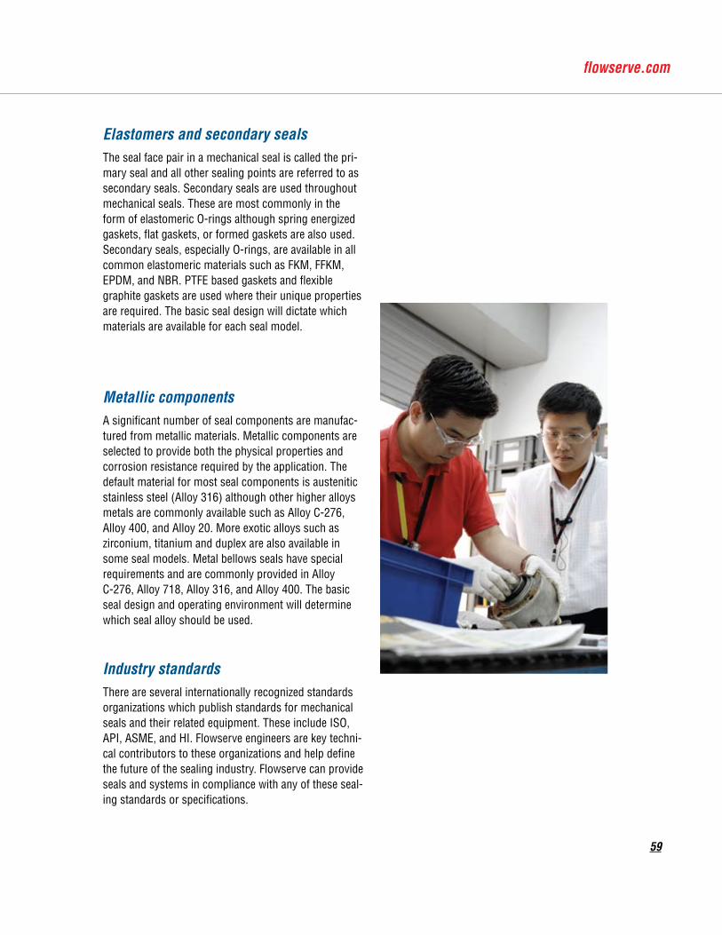
59
Elastomers and secondary sealsThe seal face pair in a mechanical seal is called the pri-mary seal and all other sealing points are referred to as secondary seals. Secondary seals are used throughout mechanical seals. These are most commonly in the form of elastomeric O-rings although spring energized gaskets, flat gaskets, or formed gaskets are also used. Secondary seals, especially O-rings, are available in all commonelastomericmaterialssuchasFKM,FFKM,EPDM, and NBR. PTFE based gaskets and flexible graphite gaskets are used where their unique properties are required. The basic seal design will dictate which materials are available for each seal model.
Metallic componentsA significant number of seal components are manufac-tured from metallic materials. Metallic components are selected to provide both the physical properties and corrosion resistance required by the application. The default material for most seal components is austenitic stainless steel (Alloy 316) although other higher alloys metals are commonly available such as Alloy C-276, Alloy 400, and Alloy 20. More exotic alloys such as zirconium, titanium and duplex are also available in some seal models. Metal bellows seals have special requirements and are commonly provided in Alloy C-276, Alloy 718, Alloy 316, and Alloy 400. The basic seal design and operating environment will determine which seal alloy should be used.
Industry standardsThere are several internationally recognized standards organizations which publish standards for mechanical seals and their related equipment. These include ISO, API,ASME,andHI.Flowserveengineersarekeytechni-cal contributors to these organizations and help define the future of the sealing industry. Flowserve can provide seals and systems in compliance with any of these seal-ing standards or specifications.

Piping Plans
60
1.2 m (4 ft.) max
0.45 - 0.6m (1.5 - 2 ft.)
lowpointdrain
VerticalEquipment
HorizontalEquipment
Mechanical Seal Piping PlansGood Piping Practices
Single Seals - Plan 23 shown
0.9 m (3 ft.) max
0.45 - 0.6 m(1.5 - 2 ft.)
high point vent
lowpointdrain
VerticalEquipment
HorizontalEquipment
Reference FTA160
Pipe size should be selected in relation to the seal size and cooling requirements. A minimum of 0.500 NPS should be used in general services and at least 0.750 NPS for API or heavy duty seals. Pipe runs should be sloped for proper venting and draining, making sure the entire loop (including the seal gland) does not include vapor traps. Vertical pumps require special attention to achieve proper venting.
Piping should be as short as possible to avoid high pipe friction losses, especially with higher viscosity barrier liquids such as oils. Sharp radius bends and gate valves in the loop must be avoided. The top of the seal gland should contain the flow outlet, while the inlet should be at the bottom or lower than the outlet.
Flowserve recognizes that one of the most effective ways to achieve long, uninterrupted mechanical seal life is to create a healthy environment around the seal faces. Piping plans help keep mechanical seals running cool and clean, promote safe handling of dangerous fluids, and extend the operational availability of rotating equipment. The following pages provide a concise summary of the most essential piping plans used successfully in today’s process plants.
Each plan shows all the standard and optional compo-nents referenced in API 682 / ISO 21049 and recom-mended by Flowserve. Consult your local Flowserve sales engineer to identify the right solution that satisfies your application requirements.
Dual Seals - Plan 53A shown
60
0.45 - 0.6(1.5 - 2
VerticalEquipment
Single Seals
VerticalEquipment
Reference FTA160
the seal gland should contain the flow outlet, while the inlet should be at the bottom or lower than the outlet.
Dual Seals - Plan 53A shown

Piping Plans
61
sealend view
inlet
Plan 11Seal flush from pump discharge through orifice.
Default single seal flush plan.
A - orifice
A
Recirculation from seal chamber to pump suction through orifice.
Standard flush plan on vertical pumps.
Plan 13
sealend view
outlet
A - orifice
A
Plan 21
sealend view
Seal flush from pump discharge through orifice and cooler.
Cooler added to Plan 11 flush increases heat removal.
inlet
A - cooling coilsB - temperature indicatorC - orifice
C A
B
1
3
2
4
Plan 23
sealend view
Seal flush from internal pumping device through cooler.
Standard flush plan in hot water services.
inlet
outlet
1
A - cooling coilsB - temperature indicatorC - cooler1 - vents, normally closed 2 - cooling out3 - cooling in4 - drain, normally closed
CA
B
3
2
4
Plan 31
sealend view
inlet
A - cyclone separator
A
Seal flush from pump discharge through cyclone separator.
Centrifuged solids are returned to pump suction.
1 - vents, normally closed2 - cooling out3 - cooling in4 - drain, normally closed
Plan 14
sealend view
inlet
outlet
A - orifice
A
Seal flush from pump discharge and recir-culation to pump suction with orifices.
Combination of Plan 11 and Plan 13.

Piping Plans
62
sealend view
D
inlet
outlet
1
C
A
B
3
2
4
inlet
A - from / to external circulating system
A
Plan 54
Plan 53CPressurized barrier fluid circulation with piston accumulator.
Fluid is circulated by a pumping ring in the dual seal assembly.
A - level indicatorB - pressure relief valveC - pressure indicatorD - pressure switch (low)E - temperature indicatorF - cooling coilsG - level switch (low)1 - vent, normally closed2 - cooling in3 - drain, normally closed4 - liquid fill, normally closed5 - cooling out
E
F
G5
sealend view
Pressurized barrier fluid circulation by external system.
outlet
Pressurized barrier fluid circulation through reservoir.
Fluid is circulated by a pumping ring in the dual seal assembly.
Plan 53A
Plan 52
Plan 32
Plan 53B
sealend view
Sealflushfromanexternalcleansource.
inlet
A - pressure indicatorB - flow indicator (optional)C - check valveD - strainerE - temperature indicator (optional)1 - flow control valve2 - from clean source, normally open
D
A
B
E
C
1
2
sealend view
Unpressurized buffer fluid circulation through reservoir.
Fluid is circulated by a pumping ring in the dual seal assembly.
inlet
outlet
A - pressure indicatorB - pressure switch (high)C - level switch (high)D - level switch (low)E - cooling coilsF - reservoirG - level indicatorH-orifice1 - vent, normally open2 - cooling in3 - drain, normally closed4 - cooling out5 - liquid fill, normally closed
1
3
24
5 C
D
AB
E
F
H
G
sealend view
inlet
outlet1
3
24
5
A - pressure indicatorB - pressure switch (low)C - level switch (high)D - level switch (low)E - cooling coilsF - reservoirG - level indicator1 - pressure source, normally open2 - cooling in3 - drain, normally closed4 - cooling out5 - liquid fill, normally closed
C
D
AB
E
F
H
G
sealend view
Pressurized barrier fluid circulation with bladder accumulator.
Fluid is circulated by a pumping ring in the dual seal assembly.
1
3
2
4 C
D
A
B
E
inlet
outlet
A - pressure indicatorB - pressure switch (low)C - finned pipe (alternative reservoir)D - temperature indicatorE - bladder accumulator1 - vent, normally closed2 - liquid fill, normally closed3 - drain, normally closed4 - pressure source, normally closed
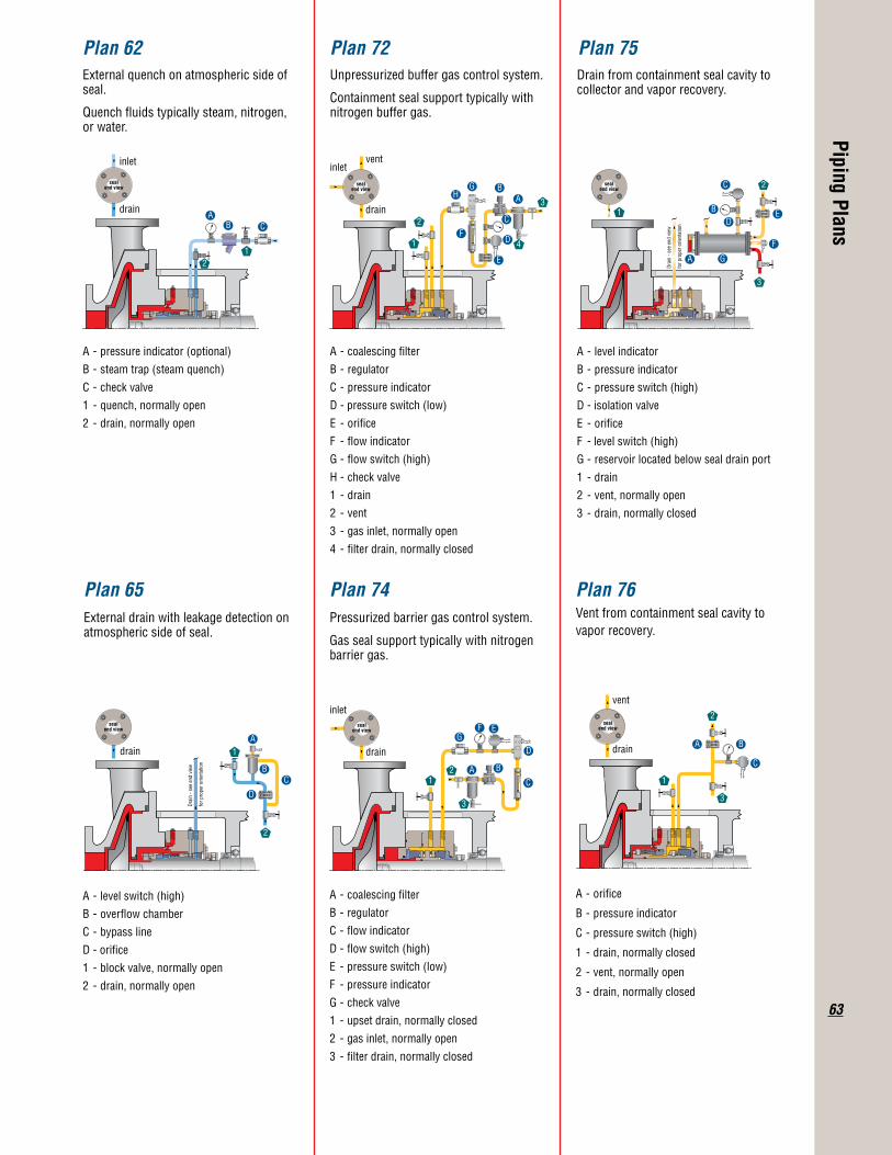
Piping Plans
63
sealend view
Dra
in -
see
end
view
for p
rope
r orie
ntat
ion
Plan 65
drain
External drain with leakage detection on atmospheric side of seal.
A - level switch (high)B - overflow chamberC - bypass lineD - orifice1 - block valve, normally open2 - drain, normally open
C
D
A
B
1
2
Plan 74
sealend view
Pressurized barrier gas control system.
Gas seal support typically with nitrogen barrier gas.
1
3
2
D
A B
EFG
C
A - coalescing filterB - regulatorC - flow indicatorD - flow switch (high)E - pressure switch (low)F - pressure indicatorG - check valve1 - upset drain, normally closed2 - gas inlet, normally open3 - filter drain, normally closed
drain
inletseal
end view
Plan 76Vent from containment seal cavity to vapor recovery.
drain
vent
1
2
3
C
A B
A - orifice
B - pressure indicator
C - pressure switch (high)
1 - drain, normally closed
2 - vent, normally open
3 - drain, normally closed
sealend view
drain
CA
B
12
Plan 62External quench on atmospheric side of seal.
Quench fluids typically steam, nitrogen, or water.
inlet
A - pressure indicator (optional)B - steam trap (steam quench)C - check valve1 - quench, normally open2 - drain, normally open
Plan 72
sealend view
drain
inletvent
Unpressurized buffer gas control system.
Containment seal support typically with nitrogen buffer gas.
1
2 C
D
AB
E
F
HG
4
A - coalescing filterB - regulatorC - pressure indicatorD - pressure switch (low)E - orificeF - flow indicatorG - flow switch (high)H-checkvalve1 - drain2 - vent3 - gas inlet, normally open4 - filter drain, normally closed
3
Plan 75Drain from containment seal cavity to collector and vapor recovery.
A - level indicatorB - pressure indicatorC - pressure switch (high)D - isolation valveE - orificeF - level switch (high)G - reservoir located below seal drain port1 - drain2 - vent, normally open3 - drain, normally closed
Dra
in -
see
end
view
for p
rope
r orie
ntat
ion
sealend view
1
2
3
C
D
A
B E
F
G
FSD101engREV06-12PrintedinUSA.
To find your local Flowserve representativeandfindoutmoreaboutFlowserveCorporation,visitwww.flowserve.com
©2012FlowserveCorporation
Flowserve Corporation has established industry leadership in the design and manufacture of its products. When properly selected, this Flowserve product is designed to perform its intended function safely during its useful life. However, the purchaser or user of Flowserve products should be aware that Flowserve products might be used in numerous applications under a wide variety of industrial service conditions. Although Flowserve can provide general guidelines, it cannot provide specific data and warnings for all possible applications. The purchaser/user must therefore assume the ultimate responsibility for the proper sizing and selection, installation, operation, and maintenance of Flowserve products. The purchaser/user should read and understand the Installation Instructions included with the product, and train its employees and contractors in the safe use of Flowserve products in connection with the specific application.
While the information and specifications contained in this literature are believed to be accurate, they are supplied for informative purposes only and should not be considered certified or as a guarantee of satisfactory results by reliance thereon. Nothing contained herein is to be construed as a warranty or guarantee, express or implied, regarding any matter with respect to this product. Because Flowserve is continually improving and upgrading its product design, the specifications, dimensions and information contained herein are subject to change without notice. Should any question arise concerning these provisions, the purchaser/user should contact Flowserve Corporation at any one of its worldwide operations or offices.
USA and CanadaKalamazoo, Michigan USATelephone: 1 269 381 2650Telefax: 1 269 382 8726
Europe, Middle East, AfricaRoosendaal, The NetherlandsTelephone: 31 165 581400Telefax: 31 165 554590
Asia PacificSingaporeTelephone: 65 6544 6800Telefax: 65 6214 0541
Latin AmericaMexico CityTelephone: 52 55 5567 7170Telefax: 52 55 5567 4224


