Existing model Mechanically Jointed Rodless Cylinder Linear Guide Type: ø25, ø32, ø40 Insert it at the notch and slide it along the mounting groove. Auto switch can be mounted in any desired position. (D-M9, D-A9) The auto switch can be fixed in any desired position with a mounting bracket. This reduces man-hours for mounting. New dust seal band improves life. The conventional groove mounting is changed to a magnetically sealed type. This means the dust seal band is always in contact with the cylinder, which reduces ingress of foreign matter, improving the life of the cylinder. New New RoHS Hexagon wrench Cushion needle Easy adjustment of cushion needle Adjustment is easier by changing the cushion needle adjustment from side to top. New New Piping can be connected from 4 directions on the head cover. Allows on-site piping to suit the installation conditions. MY1H Existing model MY1H Dust seal band Cylinder tube New New New New New New New New Mounting bracket Dust seal band Seal magnet Cylinder tube Side Front Bottom Back New New Piping ports Piping from 3 directions to 4 directions CAT.EUS20-221A-UK Series MY1H
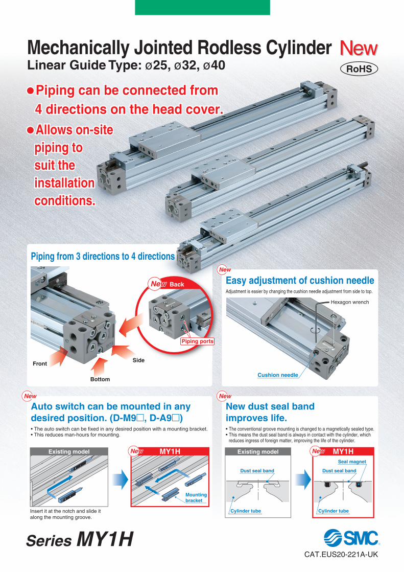
desired position. (D-M9�, D-A9�) The auto switch can be fixed in any desired position with a mounting bracket. This reduces man-hours for mounting.
New dust seal band
improves life.The conventional groove mounting is changed to a magnetically sealed type.This means the dust seal band is always in contact with the cylinder, which reduces ingress of foreign matter, improving the life of the cylinder.
NewNewRoHS
Hexagon wrench
Cushion needle
Easy adjustment of cushion needleAdjustment is easier by changing the cushion needle adjustment from side to top.
NewNew
� Piping can be connected from
4 directions on the head cover.
� Allows on-site
piping to
suit the
installation
conditions.
MY1H Existing model MY1H
Dust seal band
Cylinder tube
NewNew NewNew
NewNewNewNew
Mounting
bracket
Dust seal band
Seal magnet
Cylinder tube
SideFront
Bottom
BackNewNew
Piping ports
Piping from 3 directions to 4 directions
CAT.EUS20-221A-UK
Series MY1H
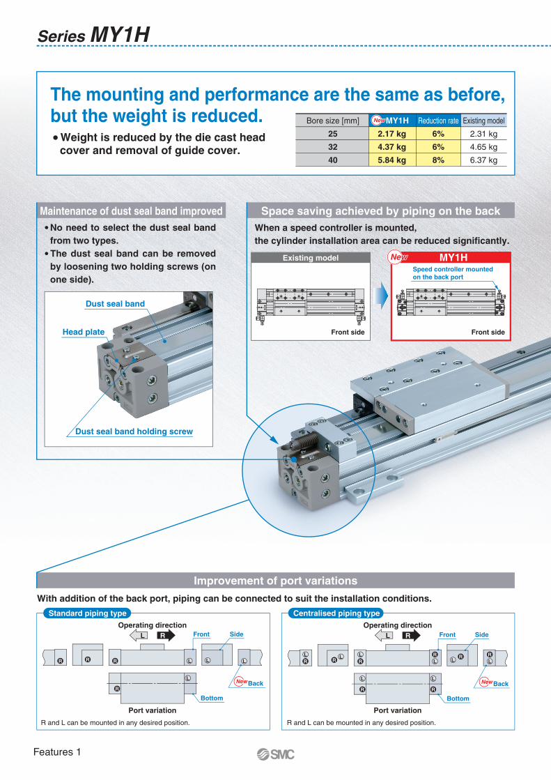
Improvement of port variations
With addition of the back port, piping can be connected to suit the installation conditions.
The mounting and performance are the same as before, but the weight is reduced.
Maintenance of dust seal band improved
Standard piping type Centralised piping type
Head plate
Dust seal band holding screw
Dust seal band
� Weight is reduced by the die cast head cover and removal of guide cover.
Bore size [mm]
25
32
40
Reduction rate
6%
6%
8%
Existing model
2.31 kg
4.65 kg
6.37 kg
MY1H
2.17 kg
4.37 kg
5.84 kg
NewNew
Operating direction
L R
Port variation
L
L LLR
R
RR
NewNew
SideFront
Bottom
Back
Operating direction
L R
Port variation
L L L
R R R L L
L
R
R
L
RR
R
SideFront
Bottom
L NewNewBack
R and L can be mounted in any desired position. R and L can be mounted in any desired position.
� No need to select the dust seal band
from two types.
� The dust seal band can be removed
by loosening two holding screws (on
one side).
Series MY1H
Space saving achieved by piping on the back
When a speed controller is mounted,
the cylinder installation area can be reduced significantly.
Front sideFront side
Existing model MY1HNewNewSpeed controller mounted
on the back port
Features 1
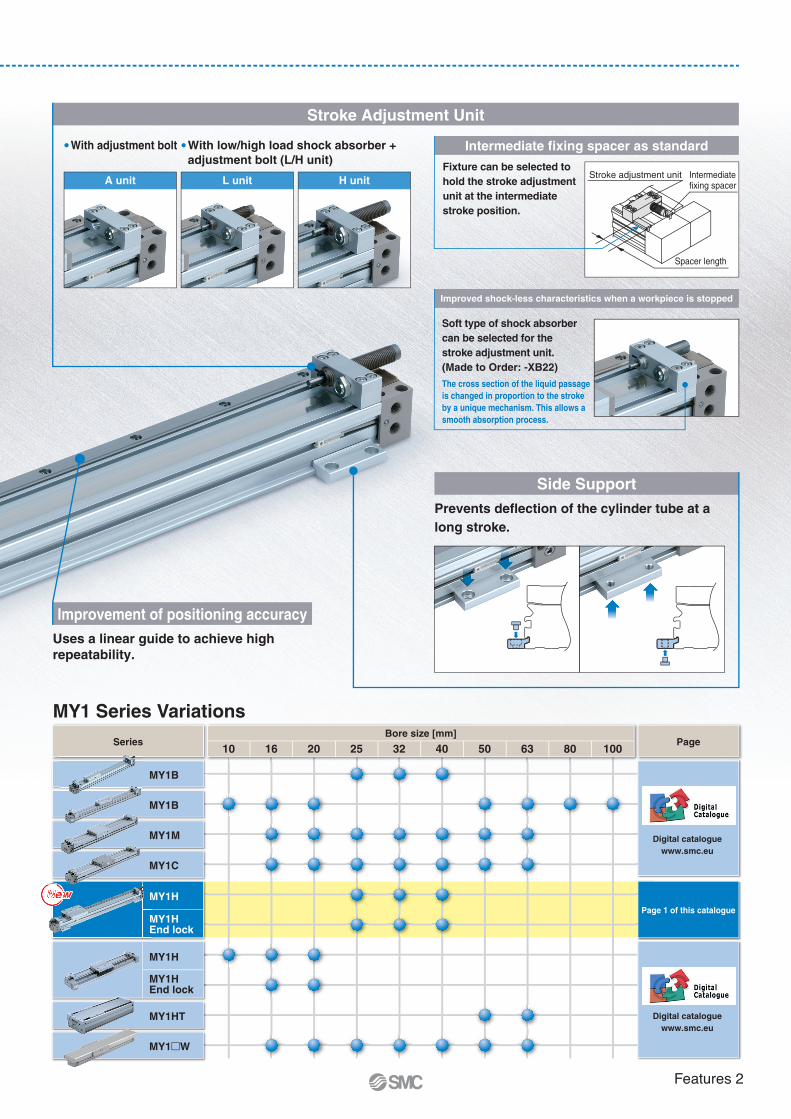
Improvement of positioning accuracy
Uses a linear guide to achieve high
repeatability.
Stroke Adjustment Unit
� With adjustment bolt � With low/high load shock absorber +
adjustment bolt (L/H unit)
The cross section of the liquid passage
is changed in proportion to the stroke
by a unique mechanism. This allows a
smooth absorption process.
Side Support
Prevents deflection of the cylinder tube at a
long stroke.
Intermediate fixing spacer as standard
Fixture can be selected to
hold the stroke adjustment
unit at the intermediate
stroke position.
Stroke adjustment unit
Spacer length
Intermediate fixing spacer
Improved shock-less characteristics when a workpiece is stopped
Soft type of shock absorber
can be selected for the
stroke adjustment unit.
(Made to Order: -XB22)
A unit L unit H unit
MY1 Series Variations
MY1B
MY1B
MY1M
MY1C
MY1H
MY1H
MY1HEnd lock
MY1HT
MY1�W
16 20 25 32 40 50 63 80 10010
Bore size [mm]Series Page
Page 1 of this catalogue
NewNew
MY1HEnd lock
MewNewwNeweewwNeNewweewwNeNewew
ME
Digital catalogue
www.smc.eu
Digital catalogue
www.smc.eu
Features 2
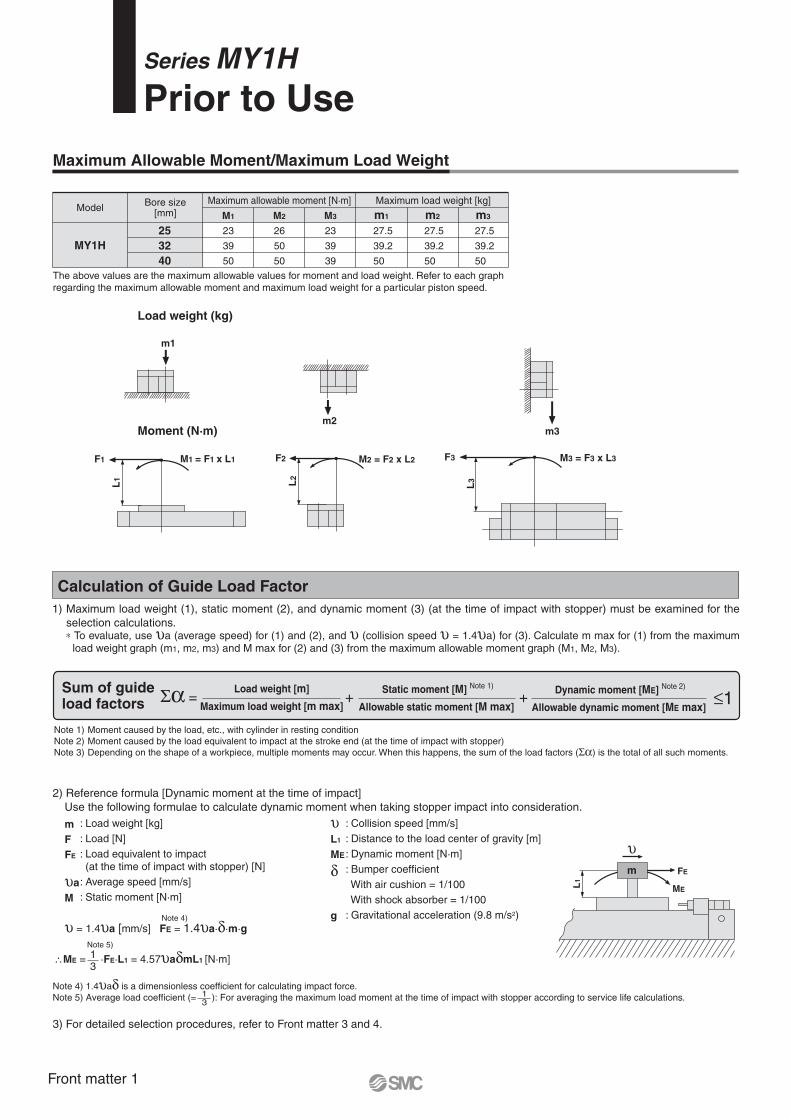
Maximum Allowable Moment/Maximum Load Weight
Model
MY1H
Bore size[mm]
25
32
40
Maximum allowable moment [N·m]
M1 M2 m2M3 m3
Maximum load weight [kg]
m1
23
39
50
26
50
50
23
39
39
27.5
39.2
50
27.5
39.2
50
27.5
39.2
50
The above values are the maximum allowable values for moment and load weight. Refer to each graph
regarding the maximum allowable moment and maximum load weight for a particular piston speed.
Load weight (kg)
Moment (N·m)
Calculation of Guide Load Factor
1) Maximum load weight (1), static moment (2), and dynamic moment (3) (at the time of impact with stopper) must be examined for the
selection calculations.∗ To evaluate, use υa (average speed) for (1) and (2), and υ (collision speed υ = 1.4υa) for (3). Calculate m max for (1) from the maximum
load weight graph (m1, m2, m3) and M max for (2) and (3) from the maximum allowable moment graph (M1, M2, M3).
FE
ME
m
L1
υ
υL1
ME
δ
g
: Collision speed [mm/s]
: Distance to the load center of gravity [m]
: Dynamic moment [N·m]
: Bumper coefficient
With air cushion = 1/100
With shock absorber = 1/100
: Gravitational acceleration (9.8 m/s2)
: Load weight [kg]
: Load [N]
: Load equivalent to impact (at the time of impact with stopper) [N]
: Average speed [mm/s]
: Static moment [N·m]
2) Reference formula [Dynamic moment at the time of impact]
Use the following formulae to calculate dynamic moment when taking stopper impact into consideration.
m
F
FE
υa
M
υ = 1.4υa [mm/s] FE = 1.4υa·δ·m·g
∴ME = ·FE·L1 = 4.57υaδmL1 [N·m]
Note 4) 1.4υaδ is a dimensionless coefficient for calculating impact force.
Note 5) Average load coefficient (= ): For averaging the maximum load moment at the time of impact with stopper according to service life calculations.
3) For detailed selection procedures, refer to Front matter 3 and 4.
Note 4)
Note 5)
13
13
M1 = F1 x L1F1
L1
F2
L2
M2 = F2 x L2
m2
L3
M3 = F3 x L3F3
m3
m1
Series MY1HPrior to Use
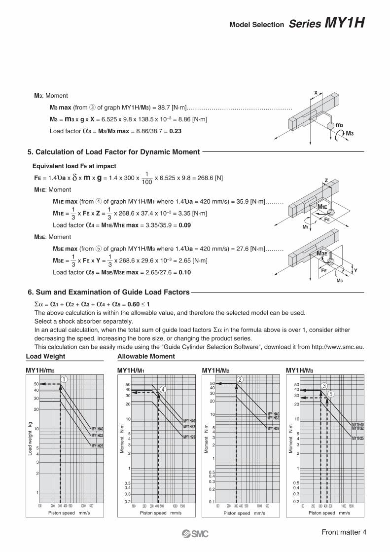
Sum of guideload factors
Load weight [m]
Maximum load weight [m max]
Static moment [M] Note 1)
Allowable static moment [M max]
Dynamic moment [ME] Note 2)
Allowable dynamic moment [ME max] Σα = + + ≤1
Note 1) Moment caused by the load, etc., with cylinder in resting condition
Note 2) Moment caused by the load equivalent to impact at the stroke end (at the time of impact with stopper)
Note 3) Depending on the shape of a workpiece, multiple moments may occur. When this happens, the sum of the load factors (Σα) is the total of all such moments.
Front matter 1
MY1H/M1
100 200 300 400 500 1000 1500
Piston speed mm/s
Mo
me
nt N
·m
10
5
4
3
2
0.5
0.4
0.3
0.2
20
30
40
50
1
MY1H40
MY1H32
MY1H25
MY1H/M3
100 200 300 400 500 1000 1500
Piston speed mm/s
Mo
me
nt N
·m
10
5
4
3
2
0.5
0.4
0.3
0.2
20
30
40
50
1
MY1H40MY1H32
MY1H25
MY1H/M2
100 200 300 400 500 1000 1500
Piston speed mm/s
Mo
me
nt N
·m
10
5
4
3
2
0.1
20
30
40
50
1
0.5
0.4
0.3
0.2
MY1H40MY1H32
MY1H25
50
40
30
20
10
5
4
3
2
1
100 200 300 400 500 1000 1500
MY1H/m1
Piston speed mm/s
Load w
eig
ht kg
Load w
eig
ht kg
Load w
eig
ht kgMY1H40
MY1H32
MY1H25
50
40
30
20
10
5
4
3
2
1
100 200 300 400 500 1000 1500
MY1H/m2
Piston speed mm/s
MY1H40
MY1H32
MY1H25
50
40
30
20
10
5
4
3
2
1
100 200 300 400 500 1000 1500
MY1H/m3
Piston speed mm/s
MY1H40
MY1H32
MY1H25
MY1H40MY1H40
MY1H32MY1H32
MY1H25MY1H25
MY1H40MY1H32
MY1H25MY1H40MY1H32
MY1H25
MY1H40
MY1H32
MY1H25
MY1H40
MY1H32
MY1H25
MY1H40
MY1H32
MY1H25
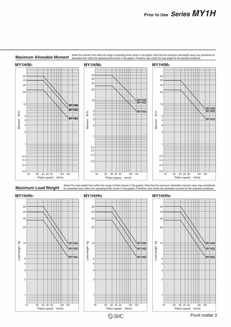
Maximum Allowable Moment
Maximum Load Weight
Select the moment from within the range of operating limits shown in the graphs. Note that the maximum load weight value may sometimes beexceeded even within the operating limits shown in the graphs. Therefore, also check the load weight for the selected conditions.
Select the load weight from within the range of limits shown in the graphs. Note that the maximum allowable moment value may sometimesbe exceeded even within the operating limits shown in the graphs. Therefore, also check the allowable moment for the selected conditions.
Prior to Use Series MY1H
Front matter 2
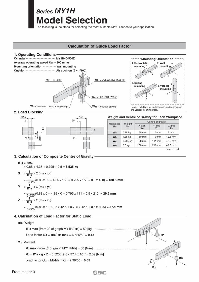
m3: Weight
m3 max (from q of graph MY1H/m3) = 50 [kg]……………………………………
Load factor α1 = m3/m3 max = 6.525/50 = 0.13
M2: Moment
M2 max (from w of graph MY1H/M2) = 50 [N·m]………………………………………………………
M2 = m3 x g x Z = 6.525 x 9.8 x 37.4 x 10−3 = 2.39 [N·m]
Load factor α2 = M2/M2 max = 2.39/50 = 0.05
1. Operating Conditions
2. Load Blocking
3. Calculation of Composite Centre of Gravity
4. Calculation of Load Factor for Static Load
m3 = Σmn
= 0.88 + 4.35 + 0.795 + 0.5 = 6.525 kg
X = x Σ (mn x xn)
= (0.88 x 65 + 4.35 x 150 + 0.795 x 150 + 0.5 x 150) = 138.5 mm
Y = x Σ (mn x yn)
= (0.88 x 0 + 4.35 x 0 + 0.795 x 111 + 0.5 x 210) = 29.6 mm
Z = x Σ (mn x zn)
= (0.88 x 5 + 4.35 x 42.5 + 0.795 x 42.5 + 0.5 x 42.5) = 37.4 mm
1m3
1m3
1m3
1
6.525
1
6.525
1
6.525
5
42.5
65
150
11
1
21
0
Y
Z X
Y
x y
z
x z
y
x
z yx y
z
Mounting Orientation
1. Horizontal
mounting
2. Wall
mounting
m3
M2
Z
m3
Calculation of Guide Load Factor
Wd: Workpiece (500 g)
Wc: MHL2-16D1 (795 g)
Wa: Connection plate t = 10 (880 g)
MY1H40-500Z Wb: MGGLB25-200 (4.35 kg)
3. Ceiling
mounting 4. Vertical
mounting
Consult with SMC for wall mounting, ceiling mounting
Stroke adjustment unit symbolFor stroke adjustment unit, refer to page 2.
Intermediate fixing spacer is not available for
end lock mounting side.
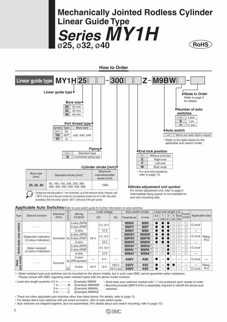
Applicable Auto Switches/Refer to auto switch guide for further information on auto switches.
A96V
A93VA90V
M9NVM9PVM9BVM9NWVM9PWVM9BWVM9NAVM9PAVM9BAV
A96
A93A90
M9NM9PM9B
M9NWM9PWM9BWM9NAM9PAM9BA
Type Special function
3-wire
(NPN equivalent)—
Grommet
24 V
24 V
2-wire
3-wire (NPN)
3-wire (PNP)
2-wire
3-wire (NPN)
3-wire (PNP)
2-wire
3-wire (NPN)
3-wire (PNP)
2-wire
No
Yes
YesGrommet
Electricalentry
Load voltageWiring
(Output)Pre-wired connector
Applicable loadDC AC
Auto switch model Lead wire length [m]
Perpendicular In-line0.5
(—)
1
(M)
5
(Z)
Diagnostic indication
(2-colour indication)
—
100 V
100 V or less
—
—
—
—
None
(N)
—
—
—
—
—
—
3
(L)
IC circuit
—
IC circuit
IC circuit
—
IC circuit
—
IC circuit
—
—
Relay,PLC
Relay,PLC
5 V
12 V
5 V, 12 V
12 V
5 V, 12 V
12 V
5 V, 12 V
12 V
Water resistant(2-colour indication)
Indi
cato
r lig
ht
So
lid
sta
te a
uto
sw
itch
Re
ed
au
to s
wit
ch
∗ Refer to the table below for the applicable auto switch model.
∗ For end lock positions, refer to page 13.Standard stroke [mm]∗
∗ Strokes are manufacturable in 1 mm increments, up to the maximum stroke. However, add
“-XB10” to the end of the part number for non-standard strokes from 51 to 599. Also when
exceeding a 600 mm stroke, specify “-XB11” at the end of the part number.
∗ Lead wire length symbols: 0.5 m ·········· — (Example) M9NW
1 m ·········· M (Example) M9NWM
3 m ·········· L (Example) M9NWL
5 m ·········· Z (Example) M9NWZ
∗ There are other applicable auto switches other than listed above. For details, refer to page 15.
∗ For details about auto switches with pre-wired connector, refer to auto switch guide.
∗ Auto switches are shipped together, (but not assembled). (For details about auto switch mounting, refer to page 15.)
∗∗ Water resistant type auto switches can be mounted on the above models, but in such case SMC cannot guarantee water resistance.
Please consult with SMC regarding water resistant types with the above model numbers.
∗ Solid state auto switches marked with “�” are produced upon receipt of order.
∗ Mounting bracket (BMY3-016) is separately required to retrofit the above auto
switches.
RoHS
Mechanically Jointed Rodless CylinderLinear Guide Type
Series MY1Hø25, ø32, ø40
1
Air cushion
270
0 to –11.5
One end (Selectable), Both ends
1 mm or less
Possible (Non-lock type)
450
0 to –12
32
700
0 to –16
Lock Specifications
Shock Absorber Specifications
Piston Speed
5 to 60
Made to
Order Made to Order(For details, refer to pages 17 and 18.)
-XB10
-XB11
-XB22
-XC56
-X168
Intermediate stroke (Using exclusive body)
Long stroke
Shock absorber/soft type RJ series mounted
With knock pin holes
Helical insert thread
Symbol Specifications
4025
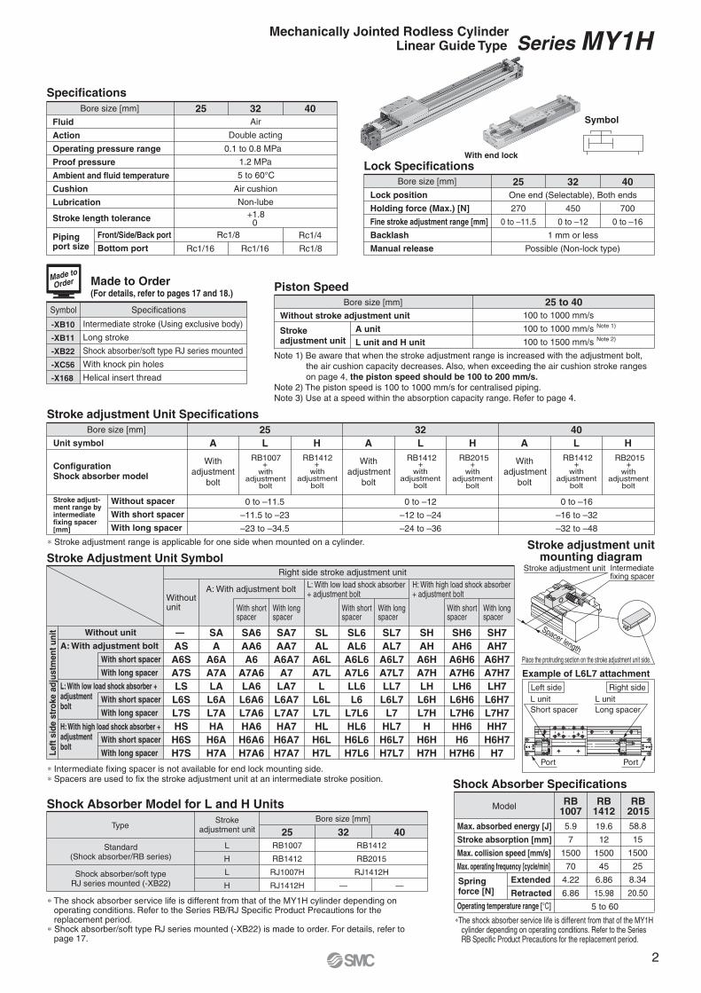
Stroke adjustment Unit Specifications
0 to –11.5
–11.5 to –23
–23 to –34.5
0 to –12
–12 to –24
–24 to –36
0 to –16
–16 to –32
–32 to –48
25
L
With
adjustment
bolt
A H
32
L
With
adjustment
bolt
A H
RB1007+
withadjustment
bolt
RB1412+
withadjustment
bolt
RB1412+
withadjustment
bolt
RB2015+
withadjustment
bolt
RB1412+
withadjustment
bolt
RB2015+
withadjustment
bolt
40
L
With
adjustment
bolt
A H
Example of L6L7 attachment
Shock Absorber Model for L and H Units
L
H
L
H
Bore size [mm]
25
RB1007
RB1412
RJ1007H
RJ1412H
RB1412
RB2015
RJ1412H
32 40
— —
Spacer length
Place the protruding section on the stroke adjustment unit side.
Intermediatefixing spacer
Stroke adjustment unit
Symbol
With end lock
Bore size [mm]
Lock position
Holding force (Max.) [N]
Fine stroke adjustment range [mm]
Backlash
Manual release
Specifications
Fluid
Action
Operating pressure range
Proof pressure
Ambient and fluid temperature
Cushion
Lubrication
Front/Side/Back port
Bottom port
25 32 40
Air
Double acting
1.2 MPa
5 to 60°C
Non-lube
0.1 to 0.8 MPa
Rc1/8
Rc1/16 Rc1/16 Rc1/8
Rc1/4Pipingport size
Bore size [mm]
Stroke length tolerance
Note 1) Be aware that when the stroke adjustment range is increased with the adjustment bolt,
the air cushion capacity decreases. Also, when exceeding the air cushion stroke ranges
on page 4, the piston speed should be 100 to 200 mm/s.
Note 2) The piston speed is 100 to 1000 mm/s for centralised piping.
Note 3) Use at a speed within the absorption capacity range. Refer to page 4.
Without stroke adjustment unit
25 to 40
A unit
L unit and H unit
Strokeadjustment unit
100 to 1000 mm/s
100 to 1000 mm/s
100 to 1500 mm/s
Note 1)
Note 2)
Bore size [mm]
Bore size [mm]
ConfigurationShock absorber model
Unit symbol
Stroke adjust-ment range byintermediatefixing spacer[mm]
Without spacer
With short spacer
With long spacer
Stroke adjustment unitmounting diagram
Left side Right side
L unit
Long spacer
Port Port
L unit
Short spacer
Stroke Adjustment Unit SymbolRight side stroke adjustment unit
Withoutunit With short
spacerWith shortspacer
With shortspacer
With longspacer
With longspacer
With longspacer
A: With adjustment boltL: With low load shock absorber+ adjustment bolt
H: With high load shock absorber+ adjustment bolt
Without unit
A: With adjustment bolt
L: With low load shock absorber +adjustmentbolt
With short spacer
With long spacer
With short spacer
With long spacer
With short spacer
With long spacer
H: With high load shock absorber +adjustmentbolt
—
AS
A6S
A7S
LS
L6S
L7S
HS
H6S
H7S
SA
A
A6A
A7A
LA
L6A
L7A
HA
H6A
H7A
SA6
AA6
A6
A7A6
LA6
L6A6
L7A6
HA6
H6A6
H7A6
SA7
AA7
A6A7
A7
LA7
L6A7
L7A7
HA7
H6A7
H7A7
SL
AL
A6L
A7L
L
L6L
L7L
HL
H6L
H7L
SL6
AL6
A6L6
A7L6
LL6
L6
L7L6
HL6
H6L6
H7L6
SL7
AL7
A6L7
A7L7
LL7
L6L7
L7
HL7
H6L7
H7L7
SH
AH
A6H
A7H
LH
L6H
L7H
H
H6H
H7H
SH6
AH6
A6H6
A7H6
LH6
L6H6
L7H6
HH6
H6
H7H6
SH7
AH7
A6H7
A7H7
LH7
L6H7
L7H7
HH7
H6H7
H7Left
sid
e s
tro
ke a
dju
stm
en
t u
nit
Strokeadjustment unit
Standard(Shock absorber/RB series)
Shock absorber/soft typeRJ series mounted (-XB22)
Type Max. absorbed energy [J]
Stroke absorption [mm]
Max. collision speed [mm/s]
Max. operating frequency [cycle/min]
Operating temperature range [°C]
Spring force [N]
Extended
Retracted
RB1007
5.9
7
1500
70
4.22
6.86
RB1412
19.6
12
1500
45
6.86
15.98
RB2015
58.8
15
1500
25
8.34
20.50
Model
+1.8 0
∗ Stroke adjustment range is applicable for one side when mounted on a cylinder.
∗ Intermediate fixing spacer is not available for end lock mounting side.∗ Spacers are used to fix the stroke adjustment unit at an intermediate stroke position.
∗ The shock absorber service life is different from that of the MY1H cylinder depending on operating conditions. Refer to the Series RB/RJ Specific Product Precautions for the replacement period.
∗ Shock absorber/soft type RJ series mounted (-XB22) is made to order. For details, refer to page 17.
∗The shock absorber service life is different from that of the MY1H cylinder depending on operating conditions. Refer to the Series RB Specific Product Precautions for the replacement period.
Series MY1HMechanically Jointed Rodless CylinderLinear Guide Type
2
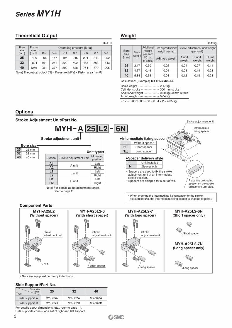
Side support A
Side support B
MY-S25A
MY-S25B
MY-S32A
MY-S32B
MY-S40A
MY-S40B
25 32 40Type
Side Support/Part No.Bore size
[mm]
For details about dimensions, etc., refer to page 14.
Side supports consist of a set of right and left support.
Unit: N
25
32
40
98
161
251
147
241
377
196
322
502
245
402
628
294
483
754
343
563
879
392
643
1005
Operating pressure [MPa]Boresize[mm]
Pistonarea
[mm2]
490
804
1256
Note) Theoretical output [N] = Pressure [MPa] x Piston area [mm2]
Boresize[mm]
25
32
40
2.17
4.37
5.84
0.30
0.46
0.55
0.02
0.04
0.08
Basicweight
Additionalweight
per each50 mm
of stroke
Side support bracketweight (per set)
A/B type weight
Stroke adjustment unit weight(per unit)
A unitweight
L unitweight
H unitweight
0.04
0.08
0.12
0.07
0.14
0.19
0.11
0.23
0.28
Unit: kg
AMYH L225 6N
Bore size253240
25 mm
32 mm
40 mm
0.80.70.60.50.40.30.2
Spacer length
Stroke adjustment unit
Theoretical Output Weight
Calculation: (Example) MY1H25-300AZ
Basic weight ·························· 2.17 kg
Cylinder stroke ······················ 300 mm stroke
Additional weight ··················· 0.30 kg/50 mm stroke
2.17 + 0.30 x 300 ÷ 50 + 0.04 x 2 ≈ 4.05 kg
A unit weight ·························· 0.04 kg
Options
Stroke Adjustment Unit/Part No.
Stroke adjustment unit
Unit type
A1A2L1L2H1H2
Stroke adjustment unit
A unit
L unit
H unit
SymbolMountingposition
Left
Right
Left
Right
Left
Right
Note) For details about adjustment range,
refer to page 2.
Intermediate fixing spacer
— Without spacer
Spacer delivery style
—
NUnit installed
Spacer only
Short spacer
Long spacer
Place the protruding section on the stroke adjustment unit side.
Intermediate
fixing spacer
Component Parts
MYH-A25L2(Without spacer)
MYH-A25L2-6(With short spacer)
MYH-A25L2-7(With long spacer)
MYH-A25L2-6N(Short spacer only)
MYH-A25L2-7N(Long spacer only)
Stroke adjustment unit
Nut
Stroke adjustment unit
Short spacer
Stroke adjustment unit
Long spacer Long spacer
Short spacer
∗ Spacers are used to fix the stroke adjustment unit at an intermediate stroke position.
∗ Spacers are shipped for a set of two.
∗ When ordering the intermediate fixing spacer for the stroke adjustment unit, the intermediate fixing spacer is shipped together.
∗ Nuts are equipped on the cylinder body.
6�7�
Series MY1H
3
2000
1500
1000
500400
300
200
1003 5 10 20 30
Load weight kg
MY1H32 Horizontal collision: P = 0.5 MPa
2000
1500
1000
500400
300
200
1003 5 10 20 50
Load weight kg
MY1H40 Horizontal collision: P = 0.5 MPa
2000
1500
1000
500400
300
200
1001 2 3 4 5 10 20 30
Load weight kg
MY1H25 Horizontal collision: P = 0.5 MPa
40 50
50 100
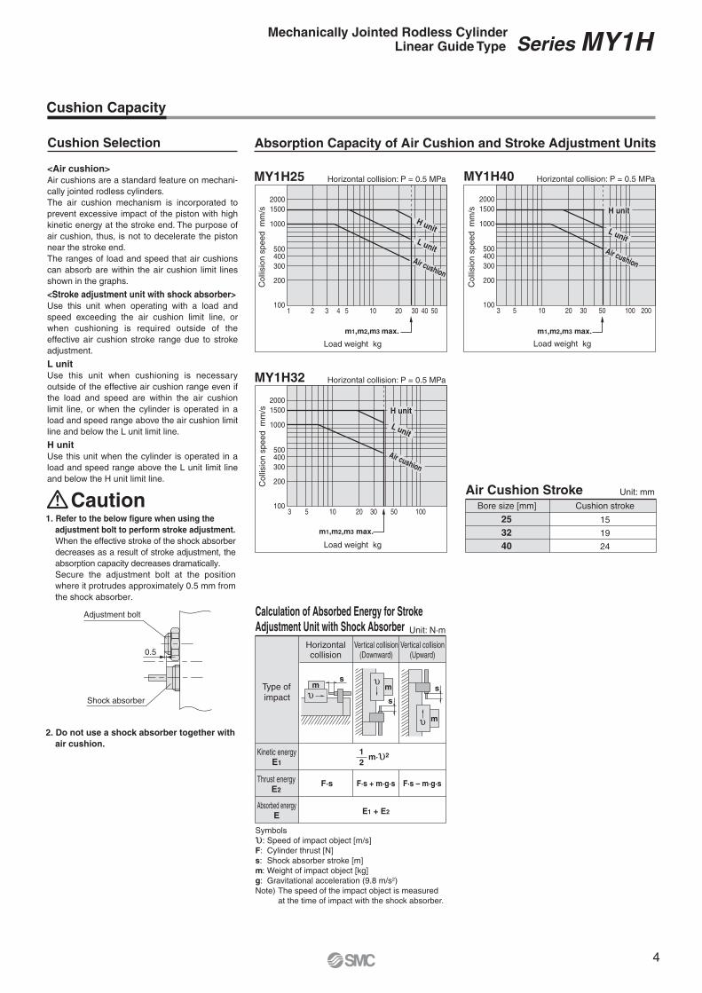
Absorption Capacity of Air Cushion and Stroke Adjustment Units
<Air cushion>
Air cushions are a standard feature on mechani-
cally jointed rodless cylinders.
The air cushion mechanism is incorporated to
prevent excessive impact of the piston with high
kinetic energy at the stroke end. The purpose of
air cushion, thus, is not to decelerate the piston
near the stroke end.
The ranges of load and speed that air cushions
can absorb are within the air cushion limit lines
shown in the graphs.
<Stroke adjustment unit with shock absorber>
Use this unit when operating with a load and
speed exceeding the air cushion limit line, or
when cushioning is required outside of the
effective air cushion stroke range due to stroke
adjustment.
L unit
Use this unit when cushioning is necessary
outside of the effective air cushion range even if
the load and speed are within the air cushion
limit line, or when the cylinder is operated in a
load and speed range above the air cushion limit
line and below the L unit limit line.
H unit
Use this unit when the cylinder is operated in a
load and speed range above the L unit limit line
and below the H unit limit line.
Air Cushion Stroke Unit: mm
Bore size [mm]
25
32
40
Cushion stroke
15
19
24
m1,m2,m3 max.
Air cushion
H unit
L unit
m1,m2,m3 max.
Air cushion
H unit
L unit
30 100 200
m1,m2,m3 max.
Air cushion
L unit
H unit
Colli
sio
n s
peed
mm
/s
Co
llisio
n s
pe
ed
m
m/s
Co
llisio
n s
pe
ed
m
m/s
Caution
Adjustment bolt
Shock absorber
0.5
Calculation of Absorbed Energy for Stroke
Adjustment Unit with Shock Absorber Unit: N·m
Horizontalcollision
Vertical collision(Downward)
Vertical collision(Upward)
Type of
impact
Kinetic energyE1
Thrust energyE2
Absorbed energyE
F·s F·s + m·g·s F·s – m·g·s
E1 + E2
ms
s
m s
m
Cushion Capacity
Cushion Selection
1
2
Symbols
υ: Speed of impact object [m/s]
F: Cylinder thrust [N]
s: Shock absorber stroke [m]
m: Weight of impact object [kg]
g: Gravitational acceleration (9.8 m/s2)
Note) The speed of the impact object is measured
at the time of impact with the shock absorber.
1. Refer to the below figure when using the
adjustment bolt to perform stroke adjustment.
When the effective stroke of the shock absorber
decreases as a result of stroke adjustment, the
absorption capacity decreases dramatically.
Secure the adjustment bolt at the position
where it protrudes approximately 0.5 mm from
the shock absorber.
2. Do not use a shock absorber together with
air cushion.
Series MY1HMechanically Jointed Rodless CylinderLinear Guide Type
4
Caution
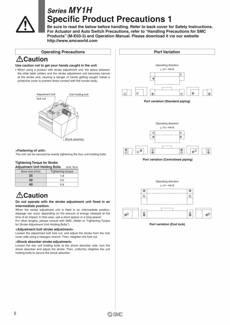
<Fastening of unit>The unit can be secured by evenly tightening the four unit holding bolts.
Do not operate with the stroke adjustment unit fixed in an
intermediate position.When the stroke adjustment unit is fixed in an intermediate position,
slippage can occur depending on the amount of energy released at the
time of an impact. In that case, use a short spacer or a long spacer.
For other lengths, please consult with SMC. (Refer to “Tightening Torque
for Stroke Adjustment Unit Holding Bolts.”)
<Adjustment bolt stroke adjustment>Loosen the adjustment bolt lock nut, and adjust the stroke from the lock
cover side using a hexagon wrench. Then, retighten the lock nut.
<Shock absorber stroke adjustment>Loosen the two unit holding bolts at the shock absorber side, turn the
shock absorber and adjust the stroke. Then, uniformly retighten the unit
holding bolts to secure the shock absorber.
Use caution not to get your hands caught in the unit.
When using a product with stroke adjustment unit, the space between
the slide table (slider) and the stroke adjustment unit becomes narrow
at the stroke end, causing a danger of hands getting caught. Install a
protective cover to prevent direct contact with the human body.
Caution
Tightening Torque for Stroke
Adjustment Unit Holding Bolts Unit: N·m
Bore size [mm]
25
32
40
Tightening torque
1.8
3.5
5.8
Operating Precautions Port Variation
Port variation (End lock)
R
Operating direction
L
Port variation (Centralised piping)
R
Operating direction
L
Port variation (Standard piping)
R
Operating direction
L
R
LR
LR
L
R
L
R
L
R
L
R
LR
L
RR
R
R
L
LLL
RL
L
R
RL
L
R
RL
RL
Shock absorber
Adjustment bolt Unit holding bolt
lock nut
Series MY1HSpecific Product Precautions 1Be sure to read the below before handling. Refer to back cover for Safety Instructions.For Actuator and Auto Switch Precautions, refer to “Handling Precautions for SMC Products” (M-E03-3) and Operation Manual. Please download it via our websitehttp://www.smcworld.com
5
With End Lock
Recommended Pneumatic Circuit
Caution
Operating Precautions
Caution
Relation to Cushion
Caution
Operating Pressure
Caution
Exhaust Speed
Caution
End Lock Mechanism Adjustment
Caution
Lock Release
Warning
Manual Release
Caution
b
a
Screwdriver, etc.
Lock piston
Lock finger
(Hole)
Lock finger
Lock finger
holding bolt
Stroke adjustment unit
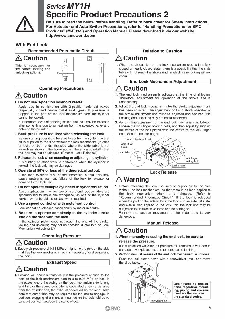
This is necessary for the correct locking and unlocking actions.
1. Locking will occur automatically if the pressure applied to the port on the lock mechanism side falls to 0.05 MPa or less. In the cases where the piping on the lock mechanism side is long and thin, or the speed controller is separated at some distance from the cylinder port, the exhaust speed will be reduced. Take note that some time may be required for the lock to engage. In addition, clogging of a silencer mounted on the solenoid valve exhaust port can produce the same effect.
1. Supply air pressure of 0.15 MPa or higher to the port on the side that has the lock mechanism, as it is necessary for disengaging the lock.
Other handling precau-tions regarding mount-ing, piping and environ-ment are the same asthe standard series.
1. When manually releasing the end lock, be sure to
release the pressure.
If it is unlocked while the air pressure still remains, it will lead to damage a workpiece, etc. due to unexpected lurching.
2. Perform manual release of the end lock mechanism as follows.
Push the lock piston down with a screwdriver, etc., and move the slide table.
1. Do not use 3-position solenoid valves.
Avoid use in combination with 3-position solenoid valves (especially closed centre metal seal types). If pressure is trapped in the port on the lock mechanism side, the cylinder cannot be locked.
Furthermore, even after being locked, the lock may be released after some time due to air leaking from the solenoid valve and entering the cylinder.
2. Back pressure is required when releasing the lock.
Before starting operation, be sure to control the system so that air is supplied to the side without the lock mechanism (in case of locks on both ends, the side where the slide table is not locked) as shown in the figure above. There is a possibility that the lock may not be released. (Refer to “Lock Release.”)
3. Release the lock when mounting or adjusting the cylinder.
If mounting or other work is performed when the cylinder is locked, the lock unit may be damaged.
4. Operate at 50% or less of the theoretical output.
If the load exceeds 50% of the theoretical output, this may cause problems such as failure of the lock to release, or damage to the lock unit.
5. Do not operate multiple cylinders in synchronisation.
Avoid applications in which two or more end lock cylinders are synchronised to move one workpiece, as one of the cylinder locks may not be able to release when required.
6. Use a speed controller with meter-out control.
Lock cannot be released occasionally by meter-in control.
7. Be sure to operate completely to the cylinder stroke end on the side with the lock.
If the cylinder piston does not reach the end of the stroke, locking and unlocking may not be possible. (Refer to “End Lock Mechanism Adjustment.”)
1. Before releasing the lock, be sure to supply air to the side without the lock mechanism, so that there is no load applied to the lock mechanism when it is released. (Refer to “Recommended Pneumatic Circuit.”) If the lock is released when the port on the side without the lock is in an exhaust state, and with a load applied to the lock unit, the lock unit may be subjected to an excessive force and be damaged. Furthermore, sudden movement of the slide table is very dangerous.
1. The end lock mechanism is adjusted at the time of shipping. Therefore, adjustment for operation at the stroke end is unnecessary.
2. Adjust the end lock mechanism after the stroke adjustment unit has been adjusted. The adjustment bolt and shock absorber of the stroke adjustment unit must be adjusted and secured first. Locking and unlocking may not occur otherwise.
3. Perform fine adjustment of the end lock mechanism as follows. Loosen the lock finger holding bolts, and then adjust by aligning the centre of the lock piston with the centre of the lock finger hole. Secure the lock finger.
1. When the air cushion on the lock mechanism side is in a fully closed or nearly closed state, there is a possibility that the slide table will not reach the stroke end, in which case locking will not occur.
Series MY1HSpecific Product Precautions 2Be sure to read the below before handling. Refer to back cover for Safety Instructions.For Actuator and Auto Switch Precautions, refer to “Handling Precautions for SMC Products” (M-E03-3) and Operation Manual. Please download it via our websitehttp://www.smcworld.com
6
SMC
#3
!2
@7
!4
#8#9$0$2 #7 @8@9o !6!0
@0
@3
!7
@2
@1
!5 #6
$1
!3
#4
#5
@6e@5 #2 q!1 t @4#1 #0 !9 i u!8 yr w
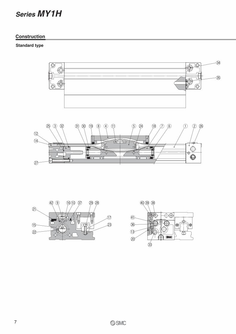
Standard type
Construction
Series MY1H
7
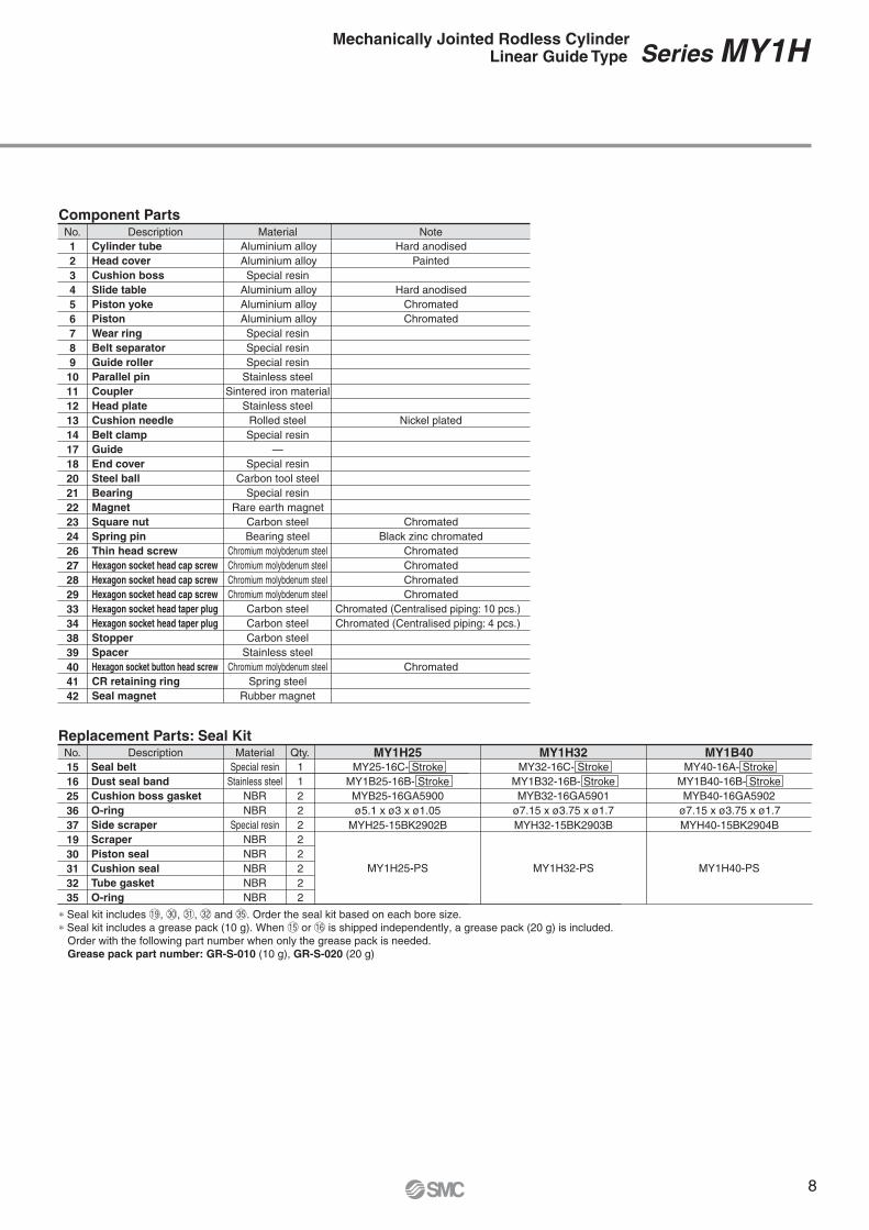
Component PartsDescription Material Note
Aluminium alloy
Aluminium alloy
Special resin
Aluminium alloy
Aluminium alloy
Aluminium alloy
Special resin
Special resin
Special resin
Stainless steel
Sintered iron material
Stainless steel
Rolled steel
Special resin
—
Special resin
Carbon tool steel
Special resin
Rare earth magnet
Carbon steel
Bearing steel
Chromium molybdenum steel
Chromium molybdenum steel
Chromium molybdenum steel
Chromium molybdenum steel
Carbon steel
Carbon steel
Carbon steel
Stainless steel
Chromium molybdenum steel
Spring steel
Rubber magnet
Hard anodised
Painted
Hard anodised
Chromated
Chromated
Nickel plated
Chromated
Black zinc chromated
Chromated
Chromated
Chromated
Chromated
Chromated (Centralised piping: 10 pcs.)
Chromated (Centralised piping: 4 pcs.)
Chromated
Cylinder tube
Head cover
Cushion boss
Slide table
Piston yoke
Piston
Wear ring
Belt separator
Guide roller
Parallel pin
Coupler
Head plate
Cushion needle
Belt clamp
Guide
End cover
Steel ball
Bearing
Magnet
Square nut
Spring pin
Thin head screw
Hexagon socket head cap screw
Hexagon socket head cap screw
Hexagon socket head cap screw
Hexagon socket head taper plug
Hexagon socket head taper plug
Stopper
Spacer
Hexagon socket button head screw
CR retaining ring
Seal magnet
No.
1
2
3
4
5
6
7
8
9
10
11
12
13
14
17
18
20
21
22
23
24
26
27
28
29
33
34
38
39
40
41
42
Description Material Qty. MY1H25Special resin
Stainless steel
NBR
NBR
Special resin
NBR
NBR
NBR
NBR
NBR
1
1
2
2
2
2
2
2
2
2
MY25-16C- Stroke
MY1B25-16B- Stroke
MYB25-16GA5900
ø5.1 x ø3 x ø1.05
MY1H25-PS
MY1H32MY32-16C- Stroke
MY1B32-16B- Stroke
MYB32-16GA5901
ø7.15 x ø3.75 x ø1.7
MY1H32-PS
MY1B40MY40-16A- Stroke
MY1B40-16B- Stroke
MYB40-16GA5902
MYH25-15BK2902B MYH32-15BK2903B MYH40-15BK2904B
ø7.15 x ø3.75 x ø1.7
MY1H40-PS
Seal belt
Dust seal band
Cushion boss gasket
O-ring
Side scraper
Scraper
Piston seal
Cushion seal
Tube gasket
O-ring
No.
15
16
25
36
37
19
30
31
32
35
Replacement Parts: Seal Kit
Series MY1HMechanically Jointed Rodless CylinderLinear Guide Type
∗ Seal kit includes !9, #0, #1, #2 and #5. Order the seal kit based on each bore size.
∗ Seal kit includes a grease pack (10 g). When !5 or !6 is shipped independently, a grease pack (20 g) is included.
Order with the following part number when only the grease pack is needed.
Grease pack part number: GR-S-010 (10 g), GR-S-020 (20 g)
8
!9@2 @0 @1
S
!4
!8!7
e
!5 !6 !3 !2!1!0
o
i
u y
t r
w
q
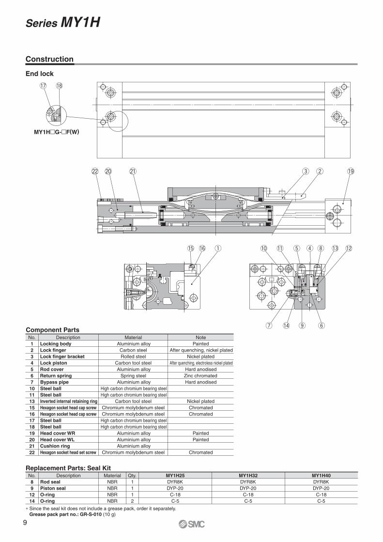
End lock
Component PartsDescription Material Note
Aluminium alloy
Carbon steel
Rolled steel
Carbon tool steel
Aluminium alloy
Spring steel
Aluminium alloy
High carbon chromium bearing steel
High carbon chromium bearing steel
Carbon tool steel
Chromium molybdenum steel
Chromium molybdenum steel
High carbon chromium bearing steel
High carbon chromium bearing steel
Aluminium alloy
Aluminium alloy
Aluminium alloy
Chromium molybdenum steel
Painted
After quenching, nickel plated
Nickel plated
After quenching, electroless nickel plated
Hard anodised
Zinc chromated
Hard anodised
Nickel plated
Chromated
Chromated
Painted
Painted
Chromated
Locking body
Lock finger
Lock finger bracket
Lock piston
Rod cover
Return spring
Bypass pipe
Steel ball
Steel ball
Inverted internal retaining ring
Hexagon socket head cap screw
Hexagon socket head cap screw
Steel ball
Steel ball
Head cover WR
Head cover WL
Cushion ring
Hexagon socket head set screw
No.
1
2
3
4
5
6
7
10
11
13
15
16
17
18
19
20
21
22
Description Material Qty.
NBR
NBR
NBR
NBR
1
1
1
2
MY1H40
DYR8K
DYP-20
C-18
C-5
MY1H25
DYR8K
DYP-20
C-18
C-5
MY1H32
DYR8K
DYP-20
C-18
C-5
Rod seal
Piston seal
O-ring
O-ring
No.
8
9
12
14
Replacement Parts: Seal Kit
Construction
MY1H�G-�F(W)
∗ Since the seal kit does not include a grease pack, order it separately.
Grease pack part no.: GR-S-010 (10 g)
Series MY1H
9
V
WX
X
R
øD Hole Size for Centralised Piping on the Bottom (Machine the mounting side to the dimensions below.)
Bottom ported
(Applicable O-ring)
WX
XW
XV Y Y
WX
(2x) 2 x ød
1616
12
(LL) L
PA
P
(Hexagon socket head taper plug)
P
(Hexagon socket head taper plug)
G
LW
NW
QW
NC
PG
GB
PF
PP
QQ
TTTUU
RR
SS
Z + Stroke
A
G
12
16
YH
NF
QQ
G
N
H
NE
NH
UU
SS
RR
(WW
W)
XX
XX
X
23.3 VV
WW
XX
XX
X
A B
View BView A
PC PE
TT
PP
1P
B
PD
SMCSMC
Guide centre line
2 x 2 x øB counterbore depth C
øLD through-hole
Workpiece mounting centre line Cylinder mounting centre line
Cushion needle
Q + Stroke
4 x MM depth M
P
(Hexagon socket head taper plug)
P
(Hexagon socket head taper plug)
P
(Hexagon socket head taper plug)
P
(Hexagon socket head taper plug)
P
(Port)
P
(Port)
P
(Port)
P
(Port)
ZZ
(Hexagon socket head taper plug)
ZZ
(Hexagon socket head taper plug)
2 x 2 x J depth K
(Hexagon socket head taper plug)
(Hexagon socket head taper plug)
(Hexagon socket head taper plug)
(Hexagon socket head taper plug)
(Hexagon socket head taper plug)
(Hexagon socket head taper plug)
MY1H�G MY1H�G
ZZ (MY1H�G)
ZZ (MY1H�G)
P (MY1H�G)
P (MY1H�G)
P (MY1H�G) P (MY1H�G)
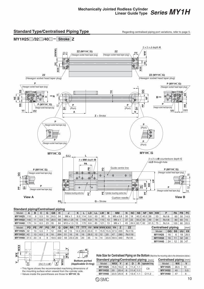
Regarding centralised piping port variations, refer to page 5.
Standard piping/Centralised piping
A B C G GB H KJ LDL LL LW M MM N NCModel NE NWNF NH
110
140
170
9
11
14
5.5
6.6
8.5
16
19
23
24.5
28.5
35
54
68
84
9.5
16
15
M6 x 1
M8 x 1.25
M10 x 1.5
5.6
6.8
8.6
114
140
170
53
70
85
90
110
121
9
13
13
M5 x 0.8
M6 x 1
M6 x 1
30
37
45
18
22
26.5
MY1H25
MY1H32
MY1H40
40.2
50.2
62.7
53
64
75
40.5
50
62
39
49
61.5
P PA
PF PPPG QWQ RR TT TTT VV WWWModel WW XXX ZYH
PB PC
PD PE ZZ
Rc1/8
Rc1/8
Rc1/4
60
80
100
5.5
6.5
8
12
16
18.5
7
8
9
42
51
59
206
264
322
15
16
23.5
14.5
16
20
20.5
16
20
23.3
28.5
35
15.5
12
14
MY1H25
MY1H32
MY1H40
11
12
14
15.5
20
23.5
220
280
340
37.5
47
59.5
50
60
80
14.5
15
20.5
32
42
37.5
13
13
23
Rc1/16
Rc1/16
Rc1/8
Centralised piping
Model QQ SS UU XX
16
16
24
6
11
12
18
32
35
26.5
40
47
[mm]
MY1H25
MY1H32
MY1H40
Centralised piping
Model WX V
26.5
40
47
10
5.5
6
[mm]
MY1H25
MY1H32
MY1H40
Standard piping/Centralised piping
Model WXX Y d D
15.5
20
23.5
16.2
20.4
25.9
6
6
8
11.4
11.4
13.4
R
1.1
1.1
1.1
Applicable O-ring
C9
C11.2
[mm]
MY1H25
MY1H32
MY1H40
Standard Type/Centralised Piping Type
MY1H25 /32 /40 ZStroke
Series MY1HMechanically Jointed Rodless CylinderLinear Guide Type
∗ This figure shows the recommended machining dimensions of the mounting surface when viewed from the cylinder side.
∗ Values inside the parentheses are those for MY1H�G.
10
SMC
SMC
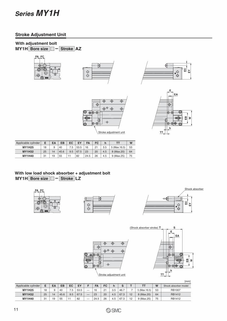
Stroke adjustment unit
E
EA
WEB
h
TT
EYEC
S
E
EA
WEB
h
TT
EYE
C
FCFA
FCFA
(Shock absorber stroke) T
Stroke adjustment unit
Shock absorber
Applicable cylinder E EA EB EC EY h TTFC WFA
MY1H25 18 9 40 7.5 53.5 16 21 3.5 535 (Max.16.5)
MY1H32 25 14 45.6 9.5 67.5 23 20 4.5 648 (Max.20)
MY1H40 31 19 55 11 82 24.5 26 4.5 9 (Max.25) 75
E EA EB EC EY h S T TTFA FC Shock absorber modelApplicable cylinder WF
Series MY1HMechanically Jointed Rodless CylinderLinear Guide Type
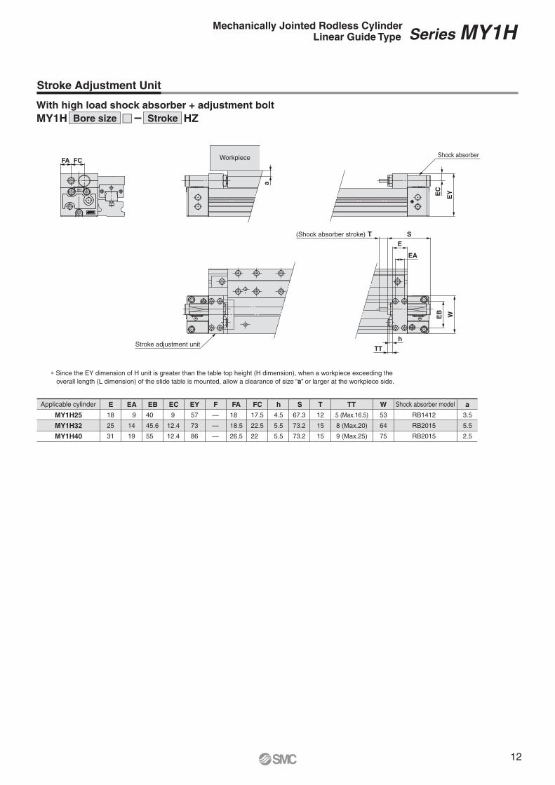
∗ Since the EY dimension of H unit is greater than the table top height (H dimension), when a workpiece exceeding the
overall length (L dimension) of the slide table is mounted, allow a clearance of size “a” or larger at the workpiece side.
12
R
øD
QQ
PP
1
QQ
SS
RR
UU
P
(Port)
P
(Port)
∗ This figure shows the recommended machining dimensions of the mounting surface when viewed from the cylinder side.
SMC SMC
L1
(LL)
PA
L
LW
NW
QW
PF
P
(Port)
Q + Stroke
PC
PG
L1
WW
XX
2 x ZZVV
2 x ZZ
WW
XX
2 x P
(Hexagon socket head taper plug)
TT UU
W3
W2
W1
NH
NEH
RR
SS
2 x P
(Hexagon socket head taper plug)
TT
Rc1/8
(Hexagon socket head taper plug)
2 x 2 x J depth K
VV
A
P
(Port)GP
P H1
H2
YH
P
(Hexagon socket head taper plug)
PD
PE
PB
P
(Hexagon socket head taper plug)
P
(Hexagon socket head taper plug)
GGB
N
NC
WX
Y 2 x 2 x ød
WX
SY
S
Long hole for stroke adjustment
(Adjustment range: 0 to TL mm)
4 x MM depth M
Long hole for stroke adjustment
(Adjustment range: 0 to TL mm)
Z + Stroke
Workpiece mounting centre line Cylinder mounting centre line
2 x 2 x øB counterbore depth C
øLD through-hole
Bottom ported
(Applicable O-ring)
Guide centre line
Standard piping/Centralised piping
A B C G GB H KJ LDL LL LW M MM N NC NE PNH NW
110
140
170
9
11
14
5.5
6.6
8.5
16
19
23
24.5
28.5
35
54
68
84
9.5
16
15
M6 x 1
M8 x 1.25
M10 x 1.5
MY1H25
MY1H32
MY1H40
PB
PG QPP RRQW SS TT UU VV XXWW YH ZZZ
PC PD
PE PF
PA
7
8
9
206
264
322
12
17
8.5
16
23
27
42
51
59
6
4
10.5
14.5
16
20
15
16
22
16
19
23
28
32
36
MY1H25
MY1H32
MY1H40
12.5
16
19.5
37.5
47
59.5
Rc1/16
Rc1/16
Rc1/8
220
280
340
60
80
100
5.6
6.8
8.6
114
140
170
53
70
85
90
110
121
9
13
13
M5 x 0.8
M6 x 1
M6 x 1
30
37
45
20
25
30.5
40.5
50
63
Rc1/8
Rc1/8
Rc1/4
39
49
61.5
53
64
75
50
60
80
14.5
15
20.5
32
42
37.5
13
13
23
5.5
6.5
8
End lock mechanism (Standard piping/Centralised piping)
TL W1 W2 W3
11.5
12
16
L1
3
6.5
10.5
H2
46
56
68.5
H1
53.5
67
83
29.3
29.3
38
27.3
27.3
35
17.7
17.7
24.4
[mm]
MY1H25
MY1H32
MY1H40
Standard piping/Centralised piping
WX Y S d
28
32
36
9
11
14
7
9.5
11.5
6
6
8
D
11.4
11.4
13.4
R
1.1
1.1
1.1
C9
C11.2
MY1H25
MY1H32
MY1H40
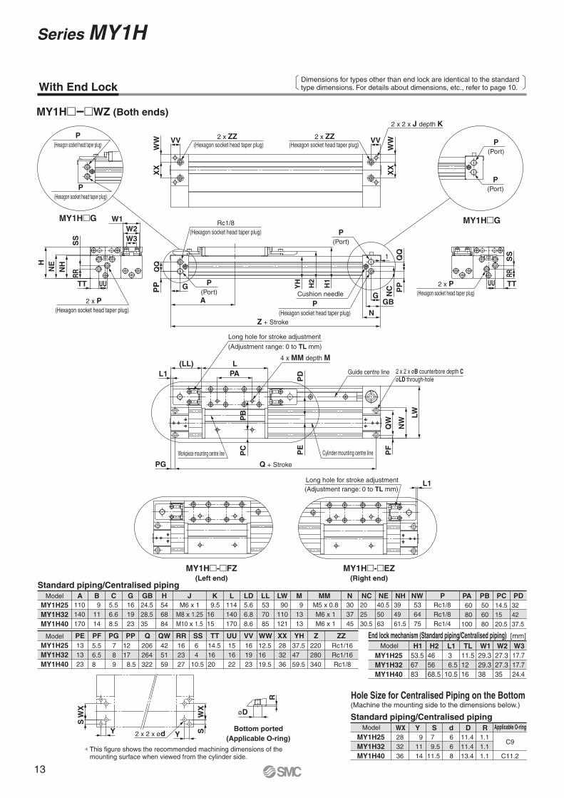
With End LockDimensions for types other than end lock are identical to the standardtype dimensions. For details about dimensions, etc., refer to page 10.
Model
Model
Model
Model
Applicable O-ring
(Machine the mounting side to the dimensions below.)
(Hexagon socket head taper plug) (Hexagon socket head taper plug)
Cushion needle
MY1H� �WZ (Both ends)
MY1H�G MY1H�G
Hole Size for Centralised Piping on the Bottom
Series MY1H
MY1H�-�EZ(Right end)
MY1H�-�FZ(Left end)
13
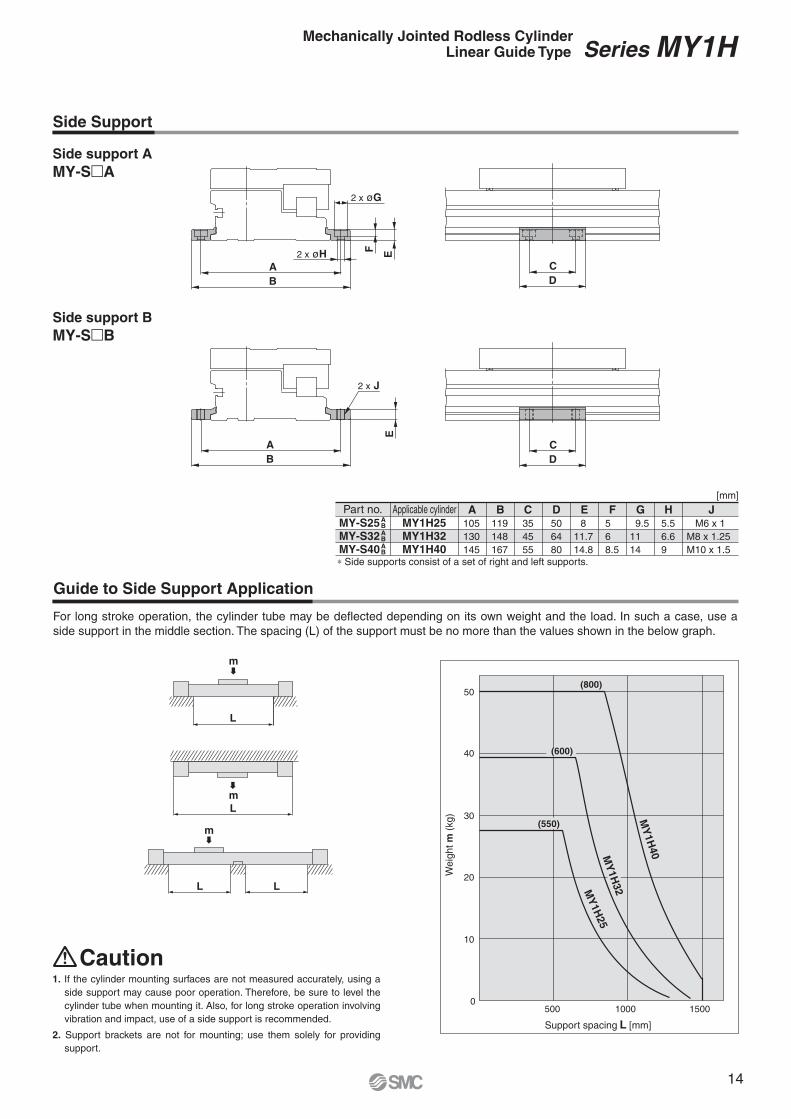
Part no.
MY-S25MY-S32MY-S40
Applicable cylinder A105
130
145
B119
148
167
C35
45
55
H5.5
6.6
9
JM6 x 1
M8 x 1.25
M10 x 1.5
E8
11.7
14.8
F5
6
8.5
G 9.5
11
14
D50
64
80
C
D
C
D
A
B
2 x øH E
F
2 x øG
A
B
E2 x J
0500 1000 1500
10
20
30
40
50
m
m
m
(800)
(600)
(550)
MY
1H
25
MY
1H
40
[mm]
L
L
L L
MY
1H
32
ABABAB
MY1H25MY1H32MY1H40
Side Support
Guide to Side Support Application
Weig
ht
m (
kg)
Support spacing L [mm]
Caution
Side support A
MY-S�A
Side support B
MY-S�B
∗ Side supports consist of a set of right and left supports.
For long stroke operation, the cylinder tube may be deflected depending on its own weight and the load. In such a case, use a
side support in the middle section. The spacing (L) of the support must be no more than the values shown in the below graph.
1. If the cylinder mounting surfaces are not measured accurately, using a
side support may cause poor operation. Therefore, be sure to level the
cylinder tube when mounting it. Also, for long stroke operation involving
vibration and impact, use of a side support is recommended.
2. Support brackets are not for mounting; use them solely for providing
support.
Series MY1HMechanically Jointed Rodless CylinderLinear Guide Type
14
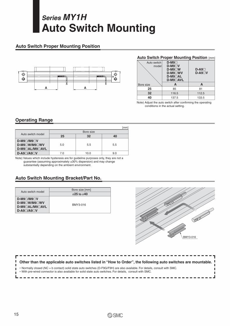
BMY3-016
D-M9BWSMCD-M9BWSMC
A AA A
25
32
40
85
116.5
137.5
81
112.5
133.5
ø25 to ø40
BMY3-016
25
5.0
7.0
32
5.5
10.0
40
5.5
9.0
[mm]
Auto Switch Proper Mounting Position
Auto Switch Proper Mounting Position [mm]
Auto switch
model
Bore size
Bore size
Note) Adjust the auto switch after confirming the operating
conditions in the actual setting.
Operating Range
Auto switch model
Note) Values which include hysteresis are for guideline purposes only, they are not a
guarantee (assuming approximately ±30% dispersion) and may change
substantially depending on the ambient environment.
Auto Switch Mounting Bracket/Part No.
Auto switch modelBore size [mm]
Series MY1HAuto Switch Mounting
∗ Normally closed (NC = b contact) solid state auto switches (D-F9G/F9H) are also available. For details, consult with SMC.
∗ With pre-wired connector is also available for solid state auto switches. For details, consult with SMC.
Other than the applicable auto switches listed in “How to Order”, the following auto switches are mountable.
D-M9�D-M9�VD-M9�WD-M9�WVD-M9�ALD-M9�AVL
D-A9�D-A9�V
D-M9�/M9�VD-M9�W/M9�WV
D-M9�AL/M9�AVLD-A9�/A9�V
D-A9�/A9�V
D-M9�/M9�V
D-M9�W/M9�WV
D-M9�AL/M9�AVL
15
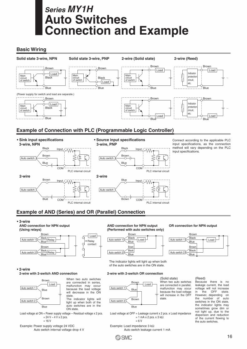
Series MY1H Auto SwitchesConnection and Example
Basic Wiring
Solid state 3-wire, NPN
s
3-wire, NPN
2-wire (Solid state)
3-wire, PNP
2-wire with 2-switch AND connection 2-wire with 2-switch OR connection
2-wire 2-wire
Solid state 3-wire, PNP
Load voltage at ON = Power supply voltage – Residual voltage x 2 pcs.
= 24 V – 4 V x 2 pcs.
= 16 V
Example: Power supply voltage 24 VDC
Auto switch internal voltage drop 4 V
Load voltage at OFF = Leakage current x 2 pcs. x Load impedance
= 1 mA x 2 pcs. x 3 kΩ
= 6 V
Example: Load impedance 3 kΩ
Auto switch leakage current 1 mA
(Power supply for switch and load are separate.)
Auto switch 1
Auto switch 2
Load
Brown
Black
Blue
Brown
Black
Blue
Auto switch 1
Brown
Auto switch 2
Black
BlueRelay
Relay
Brown
Black
Blue
Load
Relay contact
Auto switch 1
Auto switch 2
Brown
Blue
Brown
Blue
Load
Auto switch 1
Auto switch 2
Brown
Blue
Brown
Blue
Load
Main circuitof switch
Brown
Black
Blue
Load
Brown
Black
Blue
Main circuitof switch
Load
Main circuitof switch
Brown
Black
Blue
Load
Main circuitof switch
Brown
Blue
Load
Brown
Blue
Main circuitof switch
Load
Auto switch
InputBlack
COM
Brown
Blue
Auto switch
Input
Blue COM
Brown
Auto switch
InputBlack
PLC internal circuitCOM
Brown
Blue
PLC internal circuit
PLC internal circuit
PLC internal circuit
Auto switch
InputBlue
COMBrown
2-wire (Reed)
Indicator
protection
circuit,
etc.
Brown
Blue
Load
Indicator
protection
circuit,
etc.
Brown
BlueLoad
(Using relays)
Auto switch 1
Brown
Auto switch 2
Black
BlueLoad
Brown
Black
Blue
The indicator lights will light up when both
of the auto switches are in the ON state.
When two auto switches are connected in series, malfunction may occur because the load voltage will decrease in the ON state.The indicator lights will light up when both of the auto switches are in the ON state.
(Solid state)When two auto switches are connected in parallel, malfunction may occur because the load voltage will increase in the OFF state.
(Reed)Because there is no leakage current, the load voltage will not increase in the OFF state. However, depending on the number of auto switches in the ON state, the indicator lights may sometimes grow dim or not light up, due to the dispersion and reduction of the current flowing to the auto switches.
Connect according to the applicable PLC
input specifications, as the connection
method will vary depending on the PLC
input specifications.
16
Made-to-Order List
MY1H Basic type
Helical insert
thread
Shock absorber/
soft type mounted
-XB22
With knock
pin holes
-XC56 -X168
Series Type
Symbol
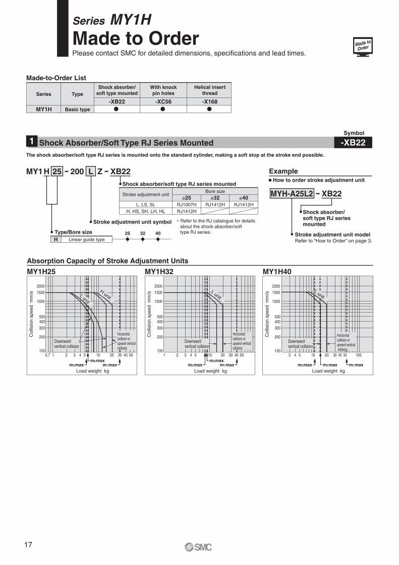
-XB22Shock Absorber/Soft Type RJ Series Mounted1
The shock absorber/soft type RJ series is mounted onto the standard cylinder, making a soft stop at the stroke end possible.
Stroke adjustment unitBore size
L, LS, SL
H, HS, SH, LH, HL
RJ1007H
RJ1412H
ø25
RJ1412H
ø32
RJ1412H
ø40
H L25MY1 XB22200 Z
Stroke adjustment unit symbol
Shock absorber/soft type RJ series mounted
Example
MYH-A25L2 XB22
Stroke adjustment unit modelRefer to “How to Order” on page 3.
Shock absorber/soft type RJ series mounted
Type/Bore size
Linear guide type
25 32 40
H
m1maxm3maxm2max
Colli
sio
n s
peed
mm
/s
Load weight kg
100
200
300
400500
1000
2000
1 2 3 4 5 10
1500
0.7 20 30 40 50
m1maxm2maxm3max
m1maxm2max m3max
Colli
sio
n s
peed
mm
/s
Load weight kg
100
200
300
400500
1000
2000
1 2 3 4 5 10
1500
20 30 40 50
Colli
sio
n s
peed
mm
/s
Load weight kg
100
200
300
400500
1000
2000
3 4 5 10
1500
20 30 40 50 100
Absorption Capacity of Stroke Adjustment Units
MY1H40MY1H25 MY1H32
Downwardvertical collision
Horizontal collision or upward verticalcollision
L unit
H unit
L unit
L unit
Downwardvertical collision
Downwardvertical collision
Horizontal collision or upward vertical collision
Horizontal collision or upward vertical collision
� How to order stroke adjustment unit
∗ Refer to the RJ catalogue for details
about the shock absorber/soft
type RJ series.
Made to
Order
Series MY1HMade to OrderPlease contact SMC for detailed dimensions, specifications and lead times.
17
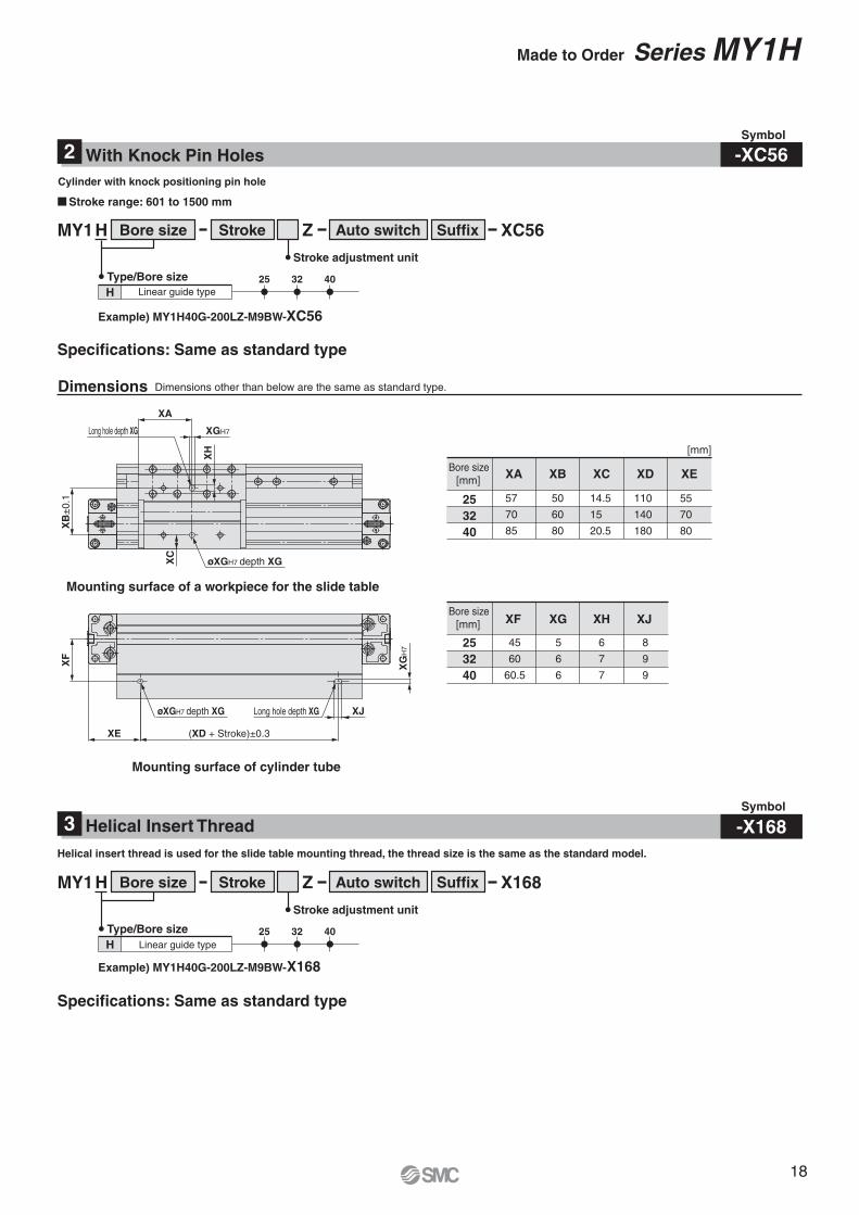
XA
Long hole depth XG XGH7
XB
±0.1
XC
XH
XF
XE (XD + Stroke)±0.3
XJ
XG
H7
øXGH7 depth XG Long hole depth XG
øXGH7 depth XG
� Stroke range: 601 to 1500 mm
Bore sizeH Stroke Auto switchMY1 Z XC56Suffix
Example) MY1H40G-200LZ-M9BW-XC56
Type/Bore size
25 32 40
H
Stroke adjustment unit
Cylinder with knock positioning pin hole
25
32
40
XA XB XC XD XEBore size
[mm]
Bore size
[mm]
[mm]
Mounting surface of a workpiece for the slide table
Mounting surface of cylinder tube
Specifications: Same as standard type
Specifications: Same as standard type
Dimensions other than below are the same as standard type.
Symbol
Symbol
-XC56With Knock Pin Holes2
-X168Helical Insert Thread3
Helical insert thread is used for the slide table mounting thread, the thread size is the same as the standard model.
Safety Instructions Be sure to read “Handling Precautions for SMC Products” (M-E03-3) before using.
SMC Corporation (Europe)
1. The compatibility of the product is the responsibility of the
person who designs the equipment or decides its specifications.Since the product specified here is used under various operating conditions, its
compatibility with specific equipment must be decided by the person who designs
the equipment or decides its specifications based on necessary analysis and test
results. The expected performance and safety assurance of the equipment will be
the responsibility of the person who has determined its compatibility with the
product. This person should also continuously review all specifications of the
product referring to its latest catalogue information, with a view to giving due
consideration to any possibility of equipment failure when configuring the
equipment.
2. Only personnel with appropriate training should operate
machinery and equipment.The product specified here may become unsafe if handled incorrectly. The
assembly, operation and maintenance of machines or equipment including our
products must be performed by an operator who is appropriately trained and
experienced.
3. . Do not service or attempt to remove product and
machinery/equipment until safety is confirmed.
1. The inspection and maintenance of machinery/equipment should only be
performed after measures to prevent falling or runaway of the driven objects
have been confirmed.
2. When the product is to be removed, confirm that the safety measures as
mentioned above are implemented and the power from any appropriate source
is cut, and read and understand the specific product precautions of all relevant
products carefully.
3. Before machinery/equipment is restarted, take measures to prevent
unexpected operation and malfunction.
4. Contact SMC beforehand and take special consideration of safety
measures if the product is to be used in any of the following
conditions.
1. Conditions and environments outside of the given specifications, or use
outdoors or in a place exposed to direct sunlight.
2. Installation on equipment in conjunction with atomic energy, railways, air
navigation, space, shipping, vehicles, military, medical treatment, combustion
and recreation, or equipment in contact with food and beverages, emergency
stop circuits, clutch and brake circuits in press applications, safety equipment
or other applications unsuitable for the standard specifications described in the
product catalogue.
3. An application which could have negative effects on people, property, or
animals requiring special safety analysis.
4. Use in an interlock circuit, which requires the provision of double interlock for
possible failure by using a mechanical protective function, and periodical
checks to confirm proper operation.
Warning
Limited warranty and Disclaimer/Compliance Requirements The product used is subject to the following “Limited warranty and Disclaimer”
and “Compliance Requirements”.
Read and accept them before using the product.
1. The product is provided for use in manufacturing industries.
The product herein described is basically provided for peaceful use in
manufacturing industries.
If considering using the product in other industries, consult SMC beforehand and
exchange specifications or a contract if necessary.
If anything is unclear, contact your nearest sales branch.
Caution
Limited warranty and Disclaimer
1. The warranty period of the product is 1 year in service or 1.5 years after
the product is delivered.∗2)
Also, the product may have specified durability, running distance or
replacement parts. Please consult your nearest sales branch.
2. For any failure or damage reported within the warranty period which is clearly our
responsibility, a replacement product or necessary parts will be provided.
This limited warranty applies only to our product independently, and not to any
other damage incurred due to the failure of the product.
3. Prior to using SMC products, please read and understand the warranty terms
and disclaimers noted in the specified catalogue for the particular products.
∗2) Vacuum pads are excluded from this 1 year warranty.
A vacuum pad is a consumable part, so it is warranted for a year after it is delivered.
Also, even within the warranty period, the wear of a product due to the use of the vacuum pad
or failure due to the deterioration of rubber material are not covered by the limited warranty.
Compliance Requirements
1. The use of SMC products with production equipment for the manufacture of
weapons of mass destruction (WMD) or any other weapon is strictly prohibited.
2. The exports of SMC products or technology from one country to another are
governed by the relevant security laws and regulations of the countries involved
in the transaction. Prior to the shipment of a SMC product to another country,
assure that all local rules governing that export are known and followed.
These safety instructions are intended to prevent hazardous situations and/or equipment damage. These instructions indicate the level of potential hazard with the labels of “Caution,” “Warning” or “Danger.” They are all important notes for safety and must be followed in addition to International Standards (ISO/IEC)∗1), and other safety regulations.
∗1) ISO 4414: Pneumatic fluid power – General rules relating to systems.
ISO 4413: Hydraulic fluid power – General rules relating to systems.
IEC 60204-1: Safety of machinery – Electrical equipment of machines.
(Part 1: General requirements)
ISO 10218-1: Manipulating industrial robots - Safety.
etc.
Caution indicates a hazard with a low level of risk which, if not avoided, could result in minor or moderate injury.
Warning indicates a hazard with a medium level of risk which, if not avoided, could result in death or serious injury.
Caution:
Warning:
Danger :Danger indicates a hazard with a high level of risk which, if not avoided, will result in death or serious injury.