Week 10, 3 May Week 11, 10 &12 May Mechanics in Energy Resources Engineering - Chapter 7 Analysis of Stress and Strain Ki B k Mi PhD Ki-Bok Min, PhD Assistant Professor E R E i i Energy Resources Engineering Seoul National University
Transcript
Week 10, 3 MayWeek 11, 10 &12 May
Mechanics in Energy Resources Engineering- Chapter 7 Analysis of Stress and Strain
Ki B k Mi PhDKi-Bok Min, PhD
Assistant ProfessorE R E i iEnergy Resources EngineeringSeoul National University
• Introduction• Plane Stress• Plane Stress• Principal Stresses and Maximum Shear Stresses• Mohr’s Circle for Plane Stress
H k ’ L f Pl St• Hooke’s Law for Plane Stress• Triaxial Stress• Plane Strain
Introduction
• Stresses in cross section
• Stresses in inclined section: larger stresses may occur Finding the normal and shear stresses acting on inclined section is – Finding the normal and shear stresses acting on inclined section is necessaryM i t t f Ch 5!– Main content of Ch.5!
?
Introduction
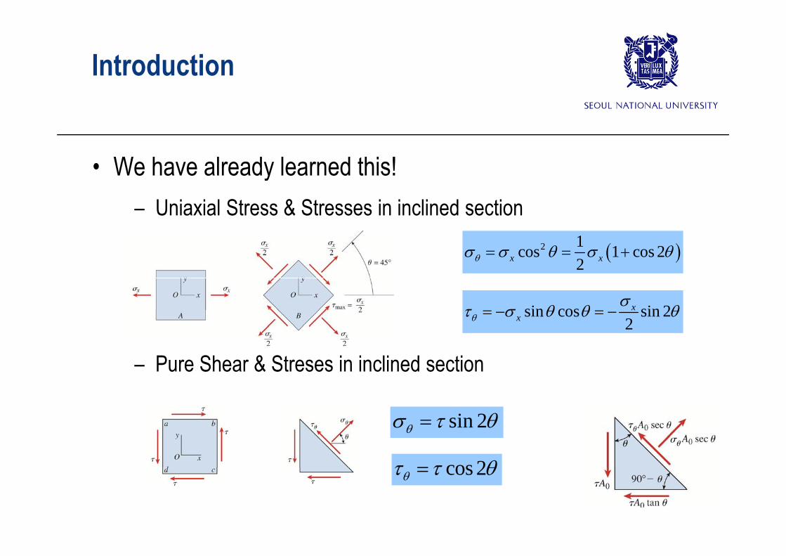
• We have already learned this!– Uniaxial Stress & Stresses in inclined sectionUniaxial Stress & Stresses in inclined section
2 1cos 1 cos 22x x
sin cos sin 22
xx
– Pure Shear & Streses in inclined section
cos 2
sin 2
cos 2
Introduction
• ONE instrinsic state of stress can be expressed in many many different ways depending on the reference axis (or orientation of element).
– Similarity to force: One intrinsic state of force (vector) can be y ( )expressed similarly depending on the reference axis.
– Difference from force: we use different transformation equations qfrom those of vectors
– Stress is NOT a vector BUT a (2nd order) tensor they do not S ess s O a ec o U a ( o de ) e so ey do ocombine according to the parallelogram law of addition
Plane StressD fi itiDefinition
• Plane Stress: Stresses in 2D plane• Normal stress σ : subscript identify the face on which the • Normal stress, σ : subscript identify the face on which the
stress act. Ex) σx
Sh t 1 t b i t d t th f hi h th • Shear stress, τ : 1st subscript denotes the face on which the stress acts, and the 2nd gives the direction on that face. Ex) τxy
acts on a positive face of an element in the positive direction of an axis (+) : acts on a positive face of an element in the positive direction of an axis (+) : plus-plus or minus-minus
acts on a positive face of an element in the negative direction of an axis (-): acts on a positive face of an element in the negative direction of an axis ( ): plus-minus or minus-plus
Positive normal & shear stresses
Plane StressD fi itiDefinition
• Shear stresses in perpendicular planes are equal in magnitude and directions shown in the below.
– Derived from the moment equilibrium
xy yx
• In 2D (plane stress) we need three (independent) • In 2D (plane stress), we need three (independent) components to describe a complete state of stress
x xy x y xy y
yx y
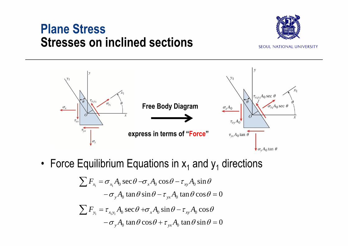
Plane StressSt i li d tiStresses on inclined sections
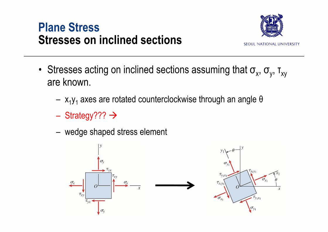
• Stresses acting on inclined sections assuming that σx, σy, τxyare known.
– x1y1 axes are rotated counterclockwise through an angle θ– Strategy??? – Strategy???
– wedge shaped stress element
Plane StressSt i li d tiStresses on inclined sections
Free Body Diagram
express in terms of “Force”
• Force Equilibrium Equations in x1 and y1 directionsiF A A A 1 1 0 0 0
0 0
sec cos sin
tan sin tan cos 0x x x xy
y yx
F A A A
A A
iF A A A 1 1 1 0 0 0
0 0
sec sin cos
tan cos tan sin 0y x y x xy
y yx
F A A A
A A
Plane StressSt i li d tiStresses on inclined sections
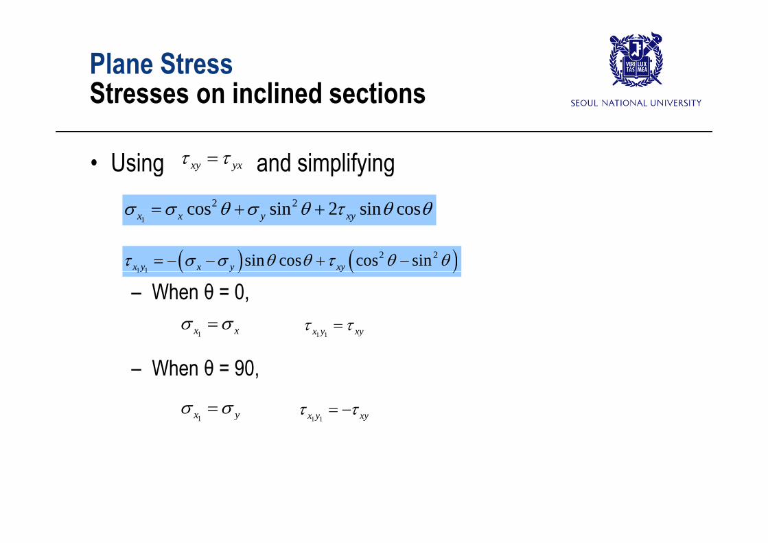
• Using and simplifyingxy yx
2 2cos sin 2 sin cos 1
cos sin 2 sin cosx x y xy
1 1
2 2sin cos cos sinx y x y xy
– When θ = 0,
1 1y y y
1x x 1 1x y xy
– When θ = 90,
1x x 1 1x y xy
1x y 1 1x y xy
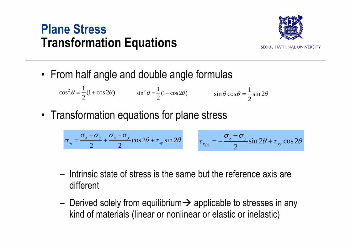
Plane StressT f ti E tiTransformation Equations
• From half angle and double angle formulas2 1cos (1 cos 2 )
2 2 1sin (1 cos 2 )
2 1sin cos sin 2
• Transformation equations for plane stress2
( )2 s cos s
2
1cos 2 sin 2
2 2x y x y
x xy
1 1sin 2 cos 2
2x y
x y xy
– Intrinsic state of stress is the same but the reference axis are different
– Derived solely from equilibrium applicable to stresses in any kind of materials (linear or nonlinear or elastic or inelastic)
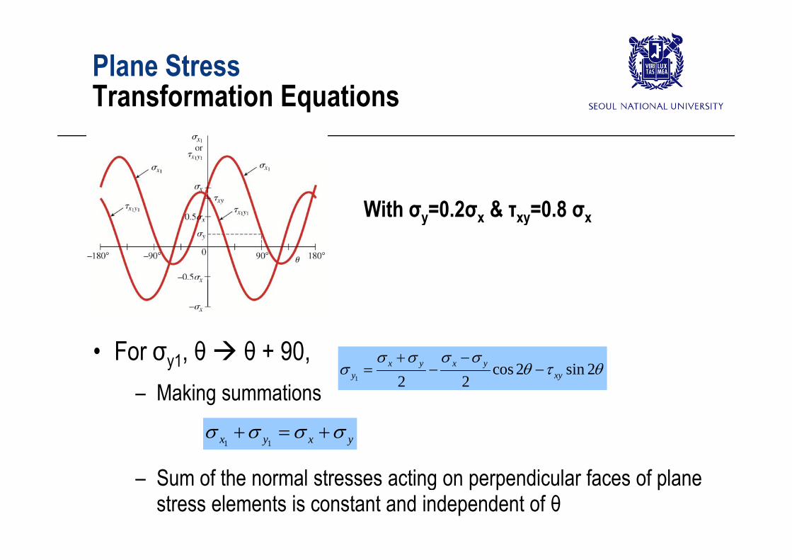
– Sum of the normal stresses acting on perpendicular faces of plane stress elements is constant and independent of θ
Plane StressS i l C f Pl StSpecial Cases of Plane Stress
• Uniaxial stress
1 cos 2x sin 2x
• Pure Shear
11 cos 2
2x 1 1
sin 22
xx y
Bi i l St
1sin 2x xy
1 1cos 2x y xy
• Biaxial Stress
1cos 2
2 2x y x y
x
1 2 2x
1 1sin 2
2x y
x y
2
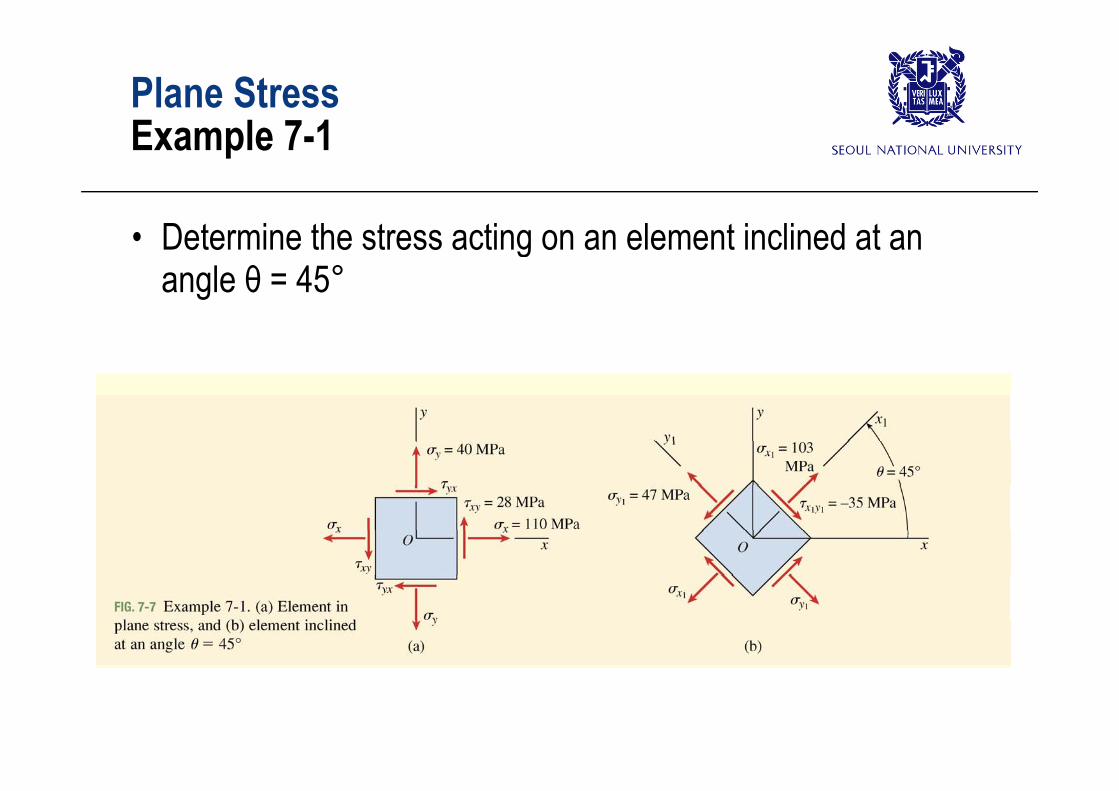
Plane StressE l 7 1Example 7-1
• Determine the stress acting on an element inclined at an angle θ = 45°
Plane StressE l 7 1Example 7-1
45°
Outline
• Introduction• Plane Stress (Transformation Equation for Plane Stress)• Plane Stress (Transformation Equation for Plane Stress)• Principal Stresses and Maximum Shear Stresses• Mohr’s Circle for Plane Stress
H k ’ L f Pl St• Hooke’s Law for Plane Stress• Triaxial Stress• Plane Strain
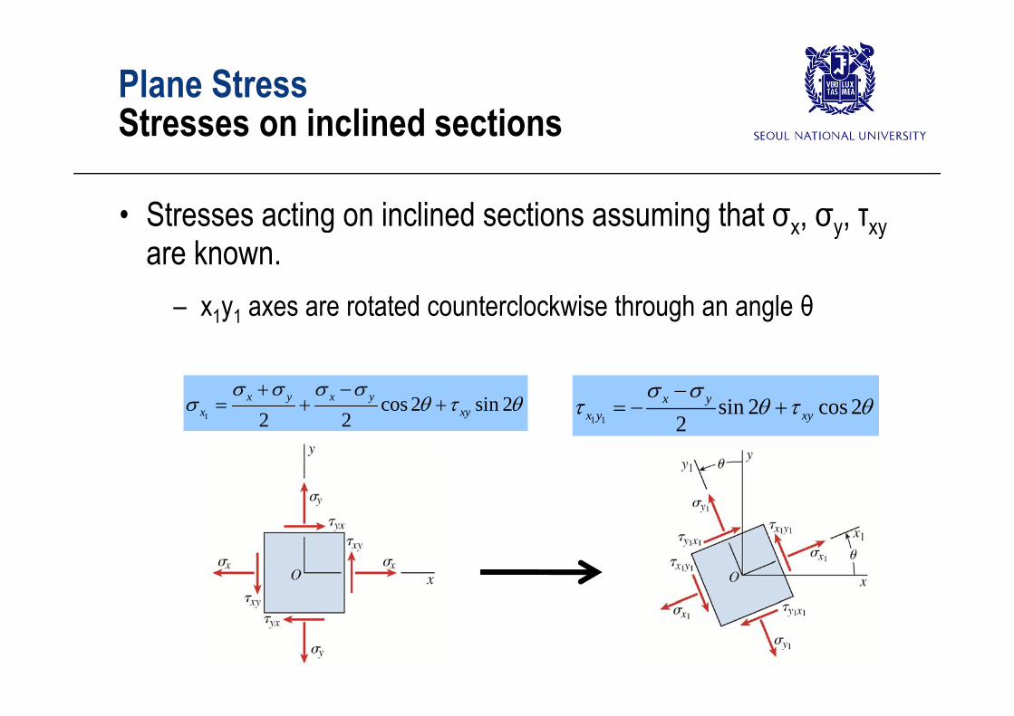
Plane StressSt i li d tiStresses on inclined sections
• Stresses acting on inclined sections assuming that σx, σy, τxyare known.
– x1y1 axes are rotated counterclockwise through an angle θ
1cos 2 sin 2
2 2x y x y
x xy
1 1sin 2 cos 2
2x y
x y xy
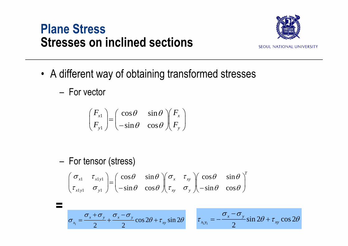
Plane StressSt i li d tiStresses on inclined sections
• A different way of obtaining transformed stresses– For vectorFor vector
1 cos sini
x xF FF F
1 sin cosy yF F
– For tensor (stress)1 1 1 cos sin cos sin T
x x y x xy 1 1 1
1 1 1
cos sin cos sinsin cos sin cos
x x y x xy
x y y xy y
=1
cos 2 sin 22 2
x y x yx xy
1 1sin 2 cos 2
2x y
x y xy
=
Outline
• Introduction• Plane Stress• Plane Stress• Principal Stresses and Maximum Shear Stresses• Mohr’s Circle for Plane Stress
H k ’ L f Pl St• Hooke’s Law for Plane Stress• Triaxial Stress• Plane Strain
Plane StressE l 7 1Example 7-1
Principal stresses
Principal stressesPrincipal stresses45°
90° 90° 90°90°
Principal angles
Principal Stresses and Maximum Shear StressesPrincipal stressesPrincipal stresses
• Principal Stresses (주응력)– Maximum normal stress & Minimum normal stressMaximum normal stress & Minimum normal stress– Strategy?
T ki d i ti f l t ith t t θ– Taking derivatives of normal stress with respect to θ
1 i 2 2 2 0xd 1 sin 2 2 cos 2 0xx y xyd
2tan 2 xy
– θp:orientation of the principal planes (planes on which the principal stresses act)
tan 2 px y
stresses act)
• Principal stresses can be obtained by substituting θp
Principal Stresses and Maximum Shear StressesPrincipal stressesPrincipal stresses
• Two values of angle 2θp: 0 °~ 360 °• One : 0 °~ 180 °
• The other (differ by 180°) : 180 °~ 360 °
• Two values of angle θp: 0 °~ 180 ° Principal anglesg p p g• One : 0 °~ 90 °
• The other (differ by 90°) : 90 °~ 180 °The other (differ by 90 ) : 90 180
principal stresses occur on mutually perpendicular planes
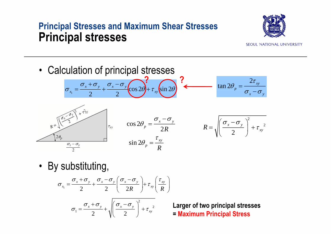
Principal Stresses and Maximum Shear StressesPrincipal stressesPrincipal stresses
• Calculation of principal stressescos 2 sin 2x y x y
? ? 2
tan 2 xyp
1cos 2 sin 2
2 2x xy px y
cos 22
x yp R
22
2x y
xyR
sin 2 xy
• By substituting,
sin 2 p R
y g,1 2 2 2
x y x y x y xyx xyR R
Larger of two principal stresses = Maximum Principal Stress
22
1 2 2x y x y
xy
Principal Stresses and Maximum Shear StressesPrincipal stressesPrincipal stresses
• The smaller of the principal stresses (= minimum principal stress)
P tti i t h t t f ti ti
1 2 x y 2
22 2 2
x y x yxy
• Putting into shear stress transformation equationsin 2 cos 2x y
x y xy
0 sin 2 cos 2x y
xy
– Shear stresses are zero on the principal stresses1 1 2x y xy 2 xy
Same equation for principal angles
• Principal stresses2 2
1,2 2 2x y x y
xy
Principal Stresses and Maximum Shear StressesPrincipal stressesPrincipal stresses
• Alternative way of finding the smaller of the principal stresses (= minimum principal stress)
B b tit ti i t th t f ti ti
cos(2 180)2
x yp R
sin(2 180) xy
p R
• By substituting into the transformation equations 2
22
x y x y
2 2 2 xy
Principal Stresses and Maximum Shear StressesPrincipal AnglesPrincipal Angles
• Principal angles correspond to principal stresses1p 1p
2p
1
2
– Both angles satisfy– Procedure to distinguish θ 1 from θ 2
tan 2 0p
Procedure to distinguish θp1 from θp2
1) Substitute these into transformation equations tell which is σ1.
2) Or find the angle that satisfies2) Or find the angle that satisfies
cos 22
x yp R
sin 2 xy
p R
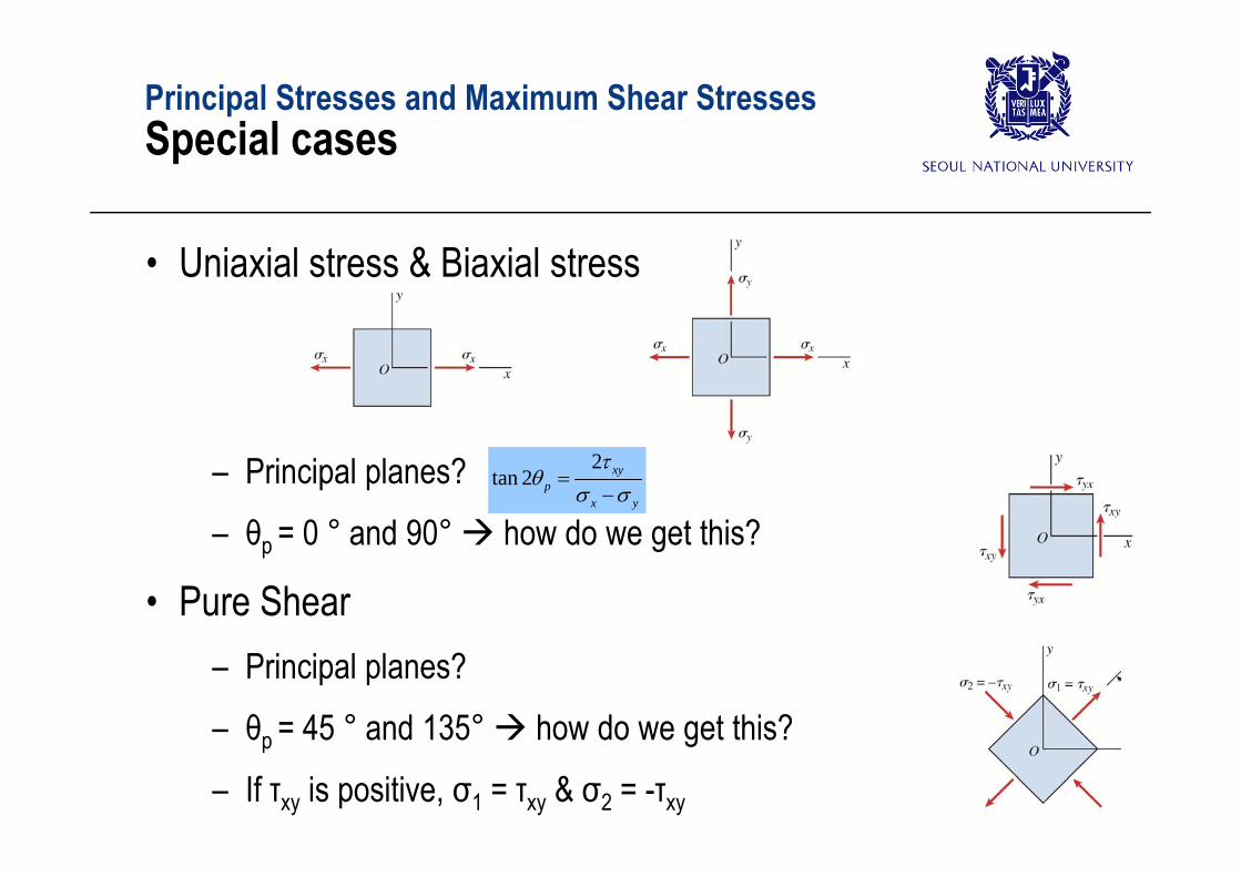
Principal Stresses and Maximum Shear StressesSpecial casesSpecial cases
• Uniaxial stress & Biaxial stress
– Principal planes?– θ = 0 ° and 90° how do we get this?
2tan 2 xy
px y
θp 0 and 90 how do we get this?
• Pure Shear– Principal planes?– θp = 45 ° and 135° how do we get this?θp 45 and 135 how do we get this?
– If τxy is positive, σ1 = τxy & σ2 = -τxy
Principal Stresses and Maximum Shear StressesThe Third Principal StressThe Third Principal Stress
• Stress element is three dimensional – Three principal stresses (σ1 ,σ2 and σ3) on three mutually Three principal stresses (σ1 ,σ2 and σ3) on three mutually
perpendicular planes
Principal Stresses and Maximum Shear StressesMaximum Shear StressMaximum Shear Stress
• Maximum Shear Stress?– Strategy?Strategy?– Taking derivatives of normal stress with respect to θ
1 1 cos 2 2 sin 2 0x yd cos 2 2 sin 2 0y
x y xyd
tan 22x y
s
– θs:orientation of the planes of the maximum positive and negative shear stresses
2 xy
• One : 0 °~ 90 °• The other (differ by 90°) : 90 °~ 180 °
-- Maximum positive and maximum negative shear stresses differ only in sign. Why???
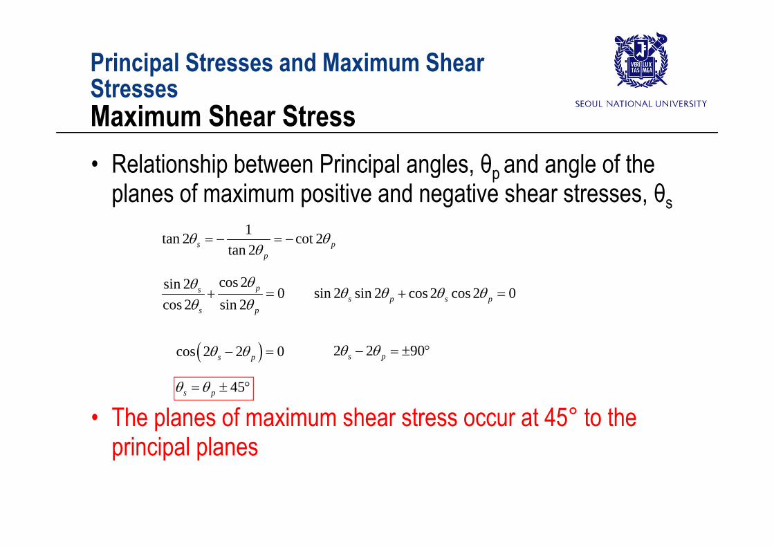
Principal Stresses and Maximum Shear StressesStressesMaximum Shear Stress• Relationship between Principal angles, θp and angle of the
planes of maximum positive and negative shear stresses, θs1tan 2 cot 2
tan 2s pp
cos 2sin 2 0cos 2 sin 2
ps
s p
sin 2 sin 2 cos 2 cos 2 0s p s p
cos 2 2 0s p 2 2 90s p
45s p
• The planes of maximum shear stress occur at 45° to the principal planesp p p
Principal Stresses and Maximum Shear StressesStressesMaximum Shear Stress
2 • sin2θs & cos2θs ?
1cos 2 xys R
1sin 2
2x y
s R
tan 22x y
s
22
2x y
xyR
1s R 1 2s R
22
max 2x y
xy
2sxy
1 1 45s p a 2 xy
1cos 2 xys R
1sin 2
2x y
s R
22
max 2x y
xy
2 1 45s p
• Maximum (positive or negative) shear stress, τmax2
2max 2
x yxy
1 2
max 2
Maximum positive shear stress is equal to one-half the difference of the principal stress
Principal Stresses and Maximum Shear StressesStressesMaximum Shear Stress• Normal stress at the plane of τmax?
x y x y 1cos 2 xys R
1cos 2 sin 2
2 2x y x y
x xy
R
1sin 22
x ys R
Normal stress acting on the planes of maximum positive shear
1 2x y
x aver
1y From Mr. Ahn’s observation
– Normal stress acting on the planes of maximum positive shear stresses equal to the average of the normal stresses on the x and y planes.y p
– And same normal stress acts on the planes of maximum negative shear stressshear stress
• Uniaxial, biaxial or pure shear?
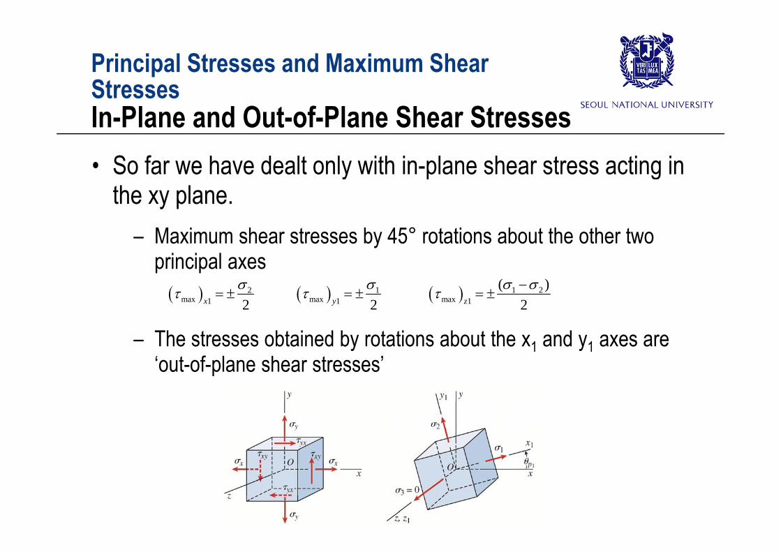
Principal Stresses and Maximum Shear StressesStressesIn-Plane and Out-of-Plane Shear Stresses• So far we have dealt only with in-plane shear stress acting in
the xy plane.– Maximum shear stresses by 45° rotations about the other two
principal axes
The stresses obtained by rotations about the x and y axes are
2max 1 2x
1max 1 2y
1 2max 1
( )2z
– The stresses obtained by rotations about the x1 and y1 axes are ‘out-of-plane shear stresses’
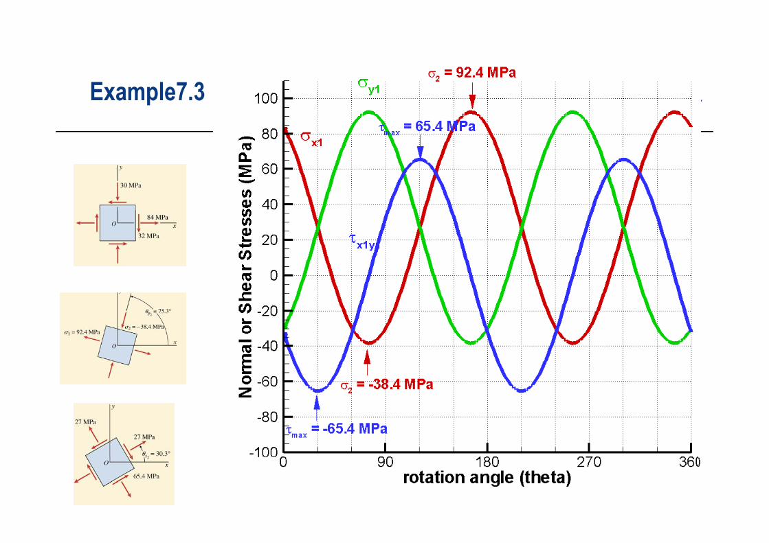
Principal Stresses and Maximum Shear StressesStressesExample 7-3
1) Determine the principal stresses and show them on a sketch of a properly oriented element
2) Determine the maximum shear stresses and show them on a properly oriented element.
E ample7 3Example7.3
Mohr’s Circle for Plane Stress
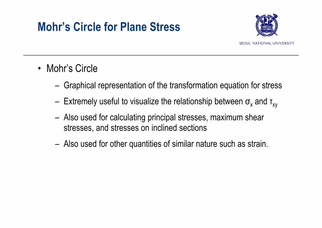
• Mohr’s Circle – Graphical representation of the transformation equation for stressGraphical representation of the transformation equation for stress– Extremely useful to visualize the relationship between σx and τxy
Al d f l l ti i i l t i h – Also used for calculating principal stresses, maximum shear stresses, and stresses on inclined sections
– Also used for other quantities of similar nature such as strain.
Mohr’s Circle for Plane StressE ti f M h ’ Ci lEquations of Mohr’s Circle
• The transformation Equations for plane stress
2 i 2x y x y
sin 2 cos 2x y
– Rearranging the above equations1
cos 2 sin 22 2
x y x yx xy
1 1sin 2 cos 2
2y
x y xy
2cos2sin
2sin2cos22
11
1
xyyx
yx
xyyxyx
x
– Square both sides of each equation and sum the two equations coss
211 xyyx
2222 )()( yxyx
– Equation of a circle in standard algebraic form111 )
2()
2( xyyxx
2220)( Ryxx
Mohr’s Circle for Plane StressE ti f M h ’ Ci lEquations of Mohr’s Circle
22211
21 )
2()
2( xy
yxyx
yxx
x y
Centre (σave, 0) Radius2 of a circle2
2x yR
2ave 2
2y
xyR
2211
21 )( Ryxavex
1xAB xO C 0,ave
Rxy
Recognized by Mohr in 188211yx
y
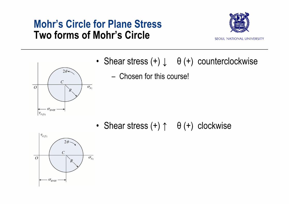
Mohr’s Circle for Plane StressT f f M h ’ Ci lTwo forms of Mohr’s Circle
• Shear stress (+) ↓ θ (+) counterclockwise– Chosen for this course!Chosen for this course!
Mohr’s Circle for Plane StressC t ti f M h ’ Ci lConstruction of Mohr’s Circle
• If stresses x, y and xy acting on the x and y faces of a stress element are known, the Mohr’s circle can be constructed in the following steps:
1. Draw a set of coordinate axes with x1 on the x-axis and x1y1 on the y-axis
2. Locate the center C of the circle at the point having x1=ave and x1y1= 0
3. Locate point A, representing the stress conditions on the x face of the element by plotting x1= x and x1y1= xy. Point A corresponds to =0°
4 Locate point B representing the stress condition on the y face of the 4. Locate point B, representing the stress condition on the y face of the element by plotting x1= y and x1y1=-xy. Point B corresponds to =90°
5. Draw a line from point A to point B. This line is a diameter and passes p p pthrough the center C. Points B and B, representing the stresses on planes 90° to each other, are at the opposite ends of the diameter, and therefore are 180° apart on the circle.are 180 apart on the circle.
6. Using point C as the center, draw Mohr’s circle through point A and B.
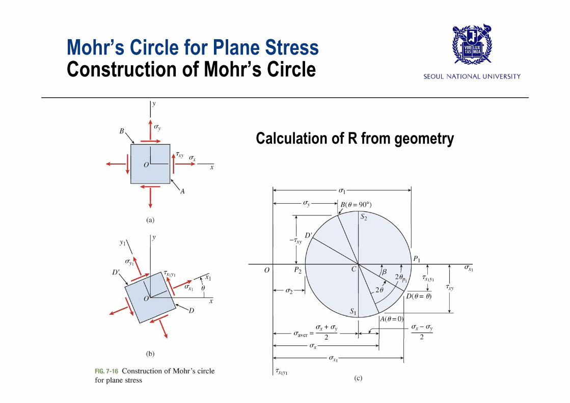
Mohr’s Circle for Plane StressC t ti f M h ’ Ci lConstruction of Mohr’s Circle
Calculation of R from geometry
Mohr’s Circle for Plane StressSt I li d El tStresses on an Inclined Element
• Stresses acting on the faces oriented at an angle θ from the x-axis.
– Measure an angle 2 θ ctw from radius CA( )D
– Angle 2θ in Mohr’s Circle corresponds to an angle θ on a stress element
1 1 1( , )x x yD
an angle θ on a stress element– We need to show that D is indeed given
by the stress transformation equationsby the stress-transformation equations
Mohr’s Circle for Plane StressSt I li d El tStresses on an Inclined Element
– From the geometry,1 cos
2x y
x R
1 1 sinx y R
– Considering the angle between the radius CA and horizontal axis,
cos(2 )2
x y
R
sin(2 ) xy
R
– Expanding this (using addition formulas),2R R
cos 2 cos sin 2 sin2
x y
R
2R
sin 2 cos cos 2 sin xy
R
R
Mohr’s Circle for Plane StressSt I li d El tStresses on an Inclined Element
– Multiplying first by cos2θ, the second by sin2θ, and then adding 1cos cos 2 sin 2x y
xy
– Multiplying first by sin2θ, the second by cos2θ, and then substracting
2 xyR
g
P tti th i t
1sin sin 2 cos 22
x yxyR
– Putting these into1 cos
2x y
x R
1 1 sinx y R
• Point D on Mohr’s circle, defined by the angle 2θ, represents the stress conditions on 1
cos 2 sin 22 2
x y x yx xy
1 1sin 2 cos 2
2x y
x y xy
, y g , pthe x1 face defined by the angle θ
Mohr’s Circle for Plane StressP i i l StPrincipal Stresses
• Principal stressesRyx
1
2
x y R
• Cosine and sine of angle 2θp1 can be obtained by inspection
R21 2 2
R
Principal stresses & Principal planes1cos 2
2x y
p R
1sin 2 xyp R
2 1 90p p
Maximum (-) shear stress
p p
Maximum (+) ( )shear stress
Mohr’s Circle for Plane StressG l C tGeneral Comments
• We can find the stresses acting on any inclined plane, as well as principal stresses and maximum shear stresses from Mohr’s Circle.
• All stresses on Mohr’s Circle in this course are in-plane All stresses on Mohr s Circle in this course are in plane stresses rotation of axes in the xy plane
S i l f • Special cases of – Uniaxial stresses– Biaxial stresses
Pure shear– Pure shear
Mohr’s Circle for Plane StressExample 7 4 (when principal stresses were given)Example 7-4 (when principal stresses were given)
• Using Mohr’s Circle, determine the stresses acting on an element inclined at an angle θ = 30°.
Mohr’s Circle for Plane StressExample 7 5 (when both normal and shear stresses Example 7-5 (when both normal and shear stresses were given)
• Using Mohr’s Circle, determine – The stresses acting on an element inclined at an angle θ = 40°The stresses acting on an element inclined at an angle θ 40– The principal stresses, and maximum shear stresses
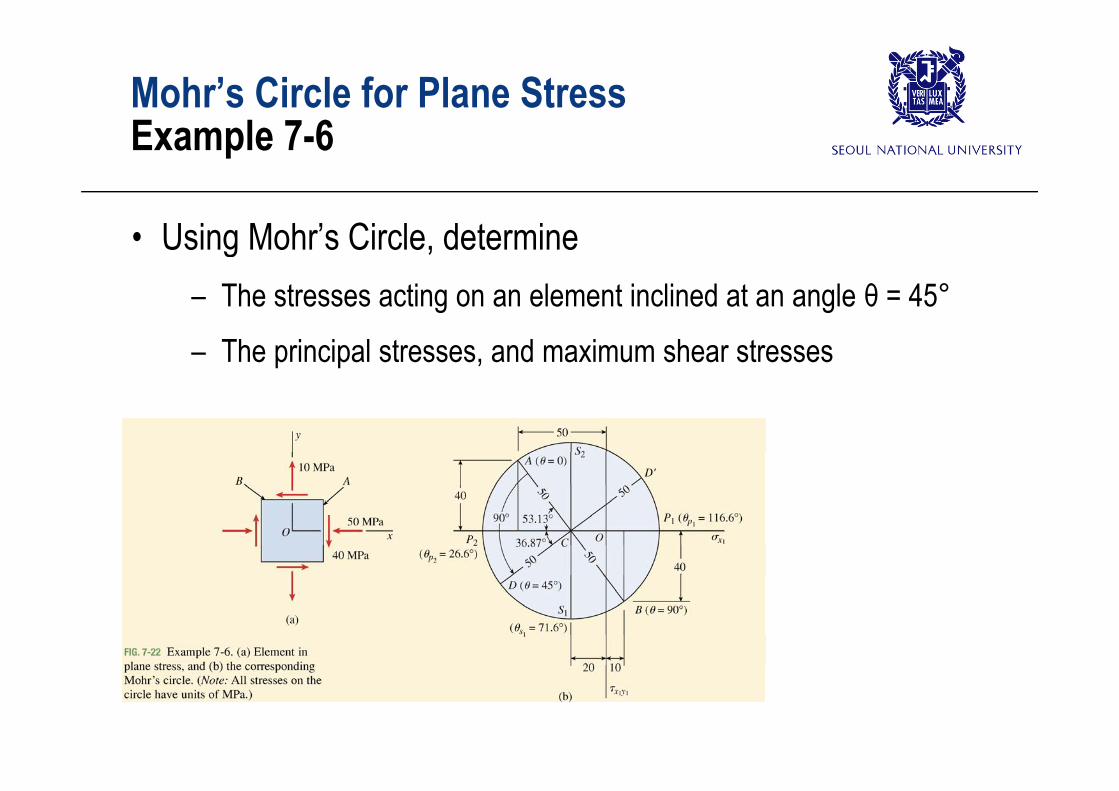
Mohr’s Circle for Plane StressE l 7 6Example 7-6
• Using Mohr’s Circle, determine – The stresses acting on an element inclined at an angle θ = 45°The stresses acting on an element inclined at an angle θ 45– The principal stresses, and maximum shear stresses
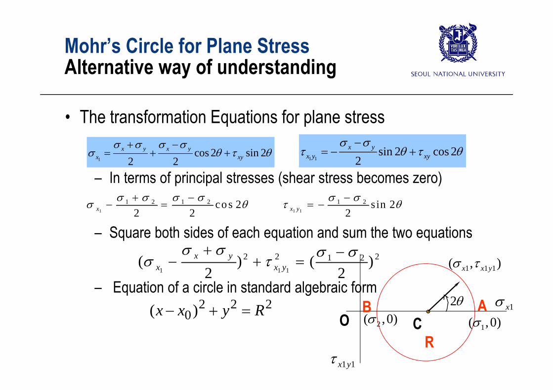
Mohr’s Circle for Plane StressAlt ti f d t diAlternative way of understanding
• The transformation Equations for plane stress
2 i 2x y x y
sin 2 cos 2x y
– In terms of principal stresses (shear stress becomes zero)1
cos 2 sin 22 2
x y x yx xy
1 1sin 2 cos 2
2y
x y xy
– Square both sides of each equation and sum the two equations1 1 1
1 2 1 2 1 2co s 2 sin 22 2 2x x y
q q q
E ti f i l i t d d l b i f1 1 1
2 2 21 2( ) ( )2 2
x yx x y
1 1 1( , )x x y
– Equation of a circle in standard algebraic form222
0)( Ryxx 1xABO C 1( ,0)2( ,0)
2
11yx
CR
1( , )
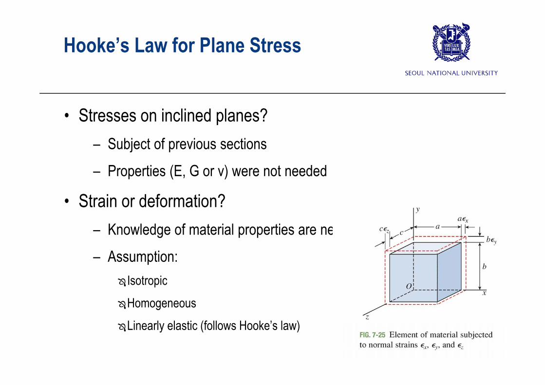
Hooke’s Law for Plane Stress
• Stresses on inclined planes?– Subject of previous sectionsSubject of previous sections– Properties (E, G or ν) were not needed
• Strain or deformation?– Knowledge of material properties are necessaryg p p y– Assumption:
• Normal strains under plane stressNormal strain, ε 1
x y +=
1x x yE
Normal strain, εx xE yE
+=E: Elastic Modulus or Young’s Modulusν: Poisson’s ratio
– Similarly
1
ν: Poisson s ratio
• Shear strains under plane stress
y y xE z x yE
– Shear strain is the decrease of angleσ and σ has no effect– σx and σy has no effect
xyxy G
G: Shear Modulus
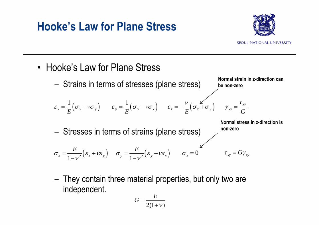
Hooke’s Law for Plane Stress
• Hooke’s Law for Plane Stress– Strains in terms of stresses (plane stress)
Normal strain in z-direction can be non-zeroStrains in terms of stresses (plane stress)
1x x yE 1
y y xE z x yE
xyxy G
be non zero
– Stresses in terms of strains (plane stress)
E E E GNormal stress in z-direction is non-zero
21x x yE
21y y xE
0z xy xyG
– They contain three material properties, but only two are independentindependent.
2(1 )EG
Hooke’s Law for Plane StressS i l Special cases
– Biaxial Stress 0, 0, 0x y xy
1x x y 1
y y x z x y 0xy x x yE
y y xE z x yE
xy
21x x yE
21y y xE
0z 0xy
– Uniaxial Stress1 x 0
0, 0, 0x y xy
P Sh
x xE y z E
0xy
x xE 0y z xy
– Pure Shear 0, 0, 0x y xy
0x y z xyxy G
0x y z xy xyG
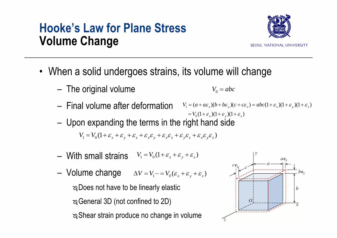
Hooke’s Law for Plane StressV l ChVolume Change
• When a solid undergoes strains, its volume will change– The original volume 0V abcThe original volume– Final volume after deformation
U di th t i th i ht h d id
0
1
0
( )( )( ) (1 )(1 )(1 )
(1 )(1 )(1 )x y z x y z
x y z
V a a b b c c abc
V
– Upon expanding the terms in the right hand side1 0 (1 )x y z x y x z y z x y zV V
– With small strains– Volume change
1 0 (1 )x y zV V
( )V V V – Volume changeDoes not have to be linearly elastic
General 3D (not confined to 2D)
1 0 ( )x y zV V V
General 3D (not confined to 2D)
Shear strain produce no change in volume
Hooke’s Law for Plane StressV l ChVolume Change
• The unit volume change (= dilatation).Ve
1x x yE
– (+) expansion, (-) contraction0
x y zeV
x x yE
1y y xE
z x yE
– Unit volume change in terms of stressplane stress or biaxial
E
0
1 2 ( )x yVe
V E
uniaxial
(1 2 )xVe
0
(1 2 )eV E
Hooke’s Law for Plane StressSt i E D it i Pl StStrain-Energy Density in Plane Stress
• Strain Energy Density, u, in Plane Stress– Strain energy stored in a unit volume of the materialStrain energy stored in a unit volume of the material
St i d it i t f t l
1 ( )2 x x y y xy xyu
– Strain energy density in terms of stresses alone2
2 21 ( 2 )2 2
xyx y x yu
E G
– Strain energy density in terms of strains alone2 2E G
22 2( 2 ) xyGEu
– Strain energy density in uniaxial stress2 ( 2 )
2(1 ) 2x y x yu
2
2xuE
2
2xEu
– Strain energy density in pure shear 2
2xyuG
2
2xyG
u
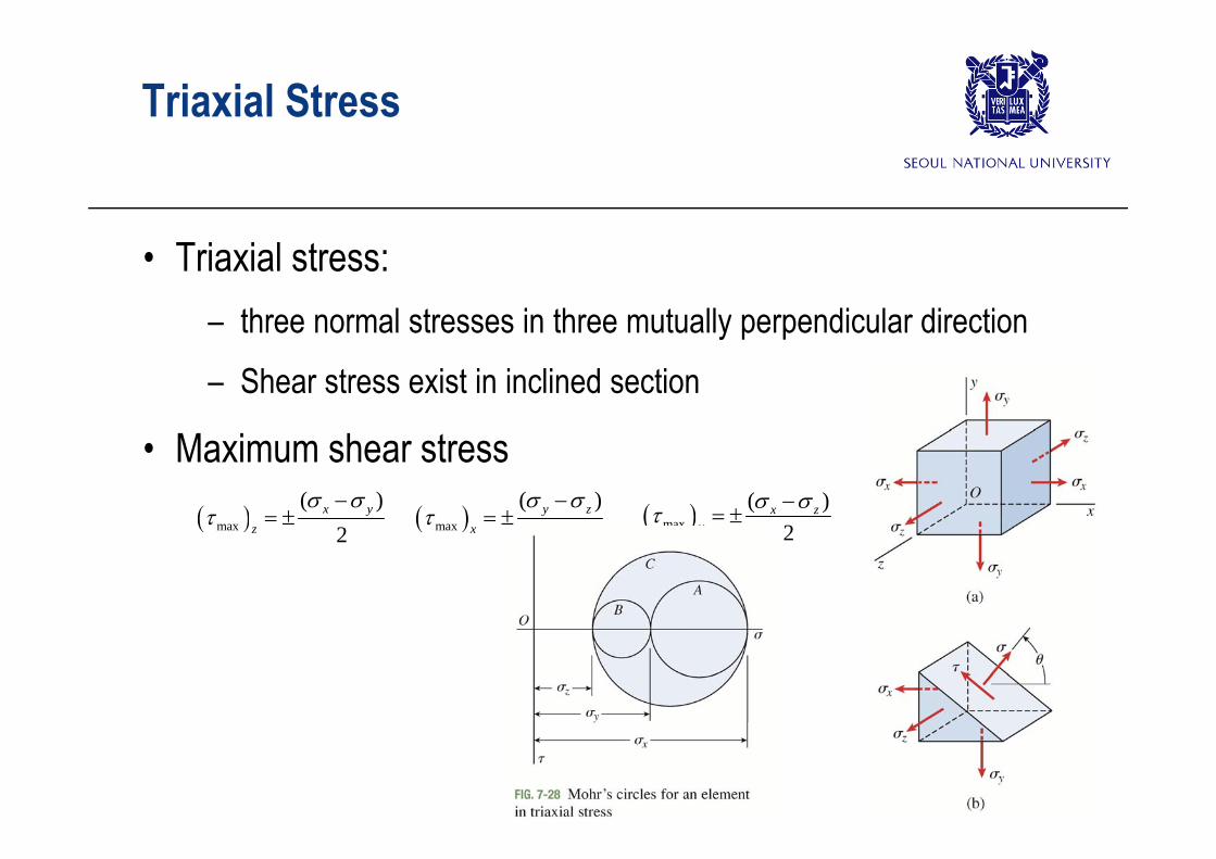
Triaxial Stress
• Triaxial stress: – three normal stresses in three mutually perpendicular directionthree normal stresses in three mutually perpendicular direction– Shear stress exist in inclined section
• Maximum shear stress max
( )2
x y
max
( )2
y z
max
( )2
x zy
max 2z max 2x
max 2y
Triaxial Stress
• Mohr’s Circles for 3D– Rotation about z-axis (A)Rotation about z axis (A)– Rotation about x-axis (B)
R t ti b t i (C) – Rotation about y-axis (C)– Rotation about skew axis (shaded area)
AC
x y z
Subject of more advanced studyA
BO O
minz max
maxx 1
max max min2 ( )
Triaxial StressH k ’ L f T i i l StHooke’s Law for Triaxial Stress
• Strains in terms of TriaxialStress
• Stresses in terms of strains
( )xx y zE E
(1 ) ( )(1 )(1 2 )x x y z
E
( )yy z xE E
(1 ) ( )(1 )(1 2 )y y z x
E
( )zz x yE E
(1 ) ( )(1 )(1 2 )z z x y
E
• Unit Volume Change
1 21 2 ( )x y zeE
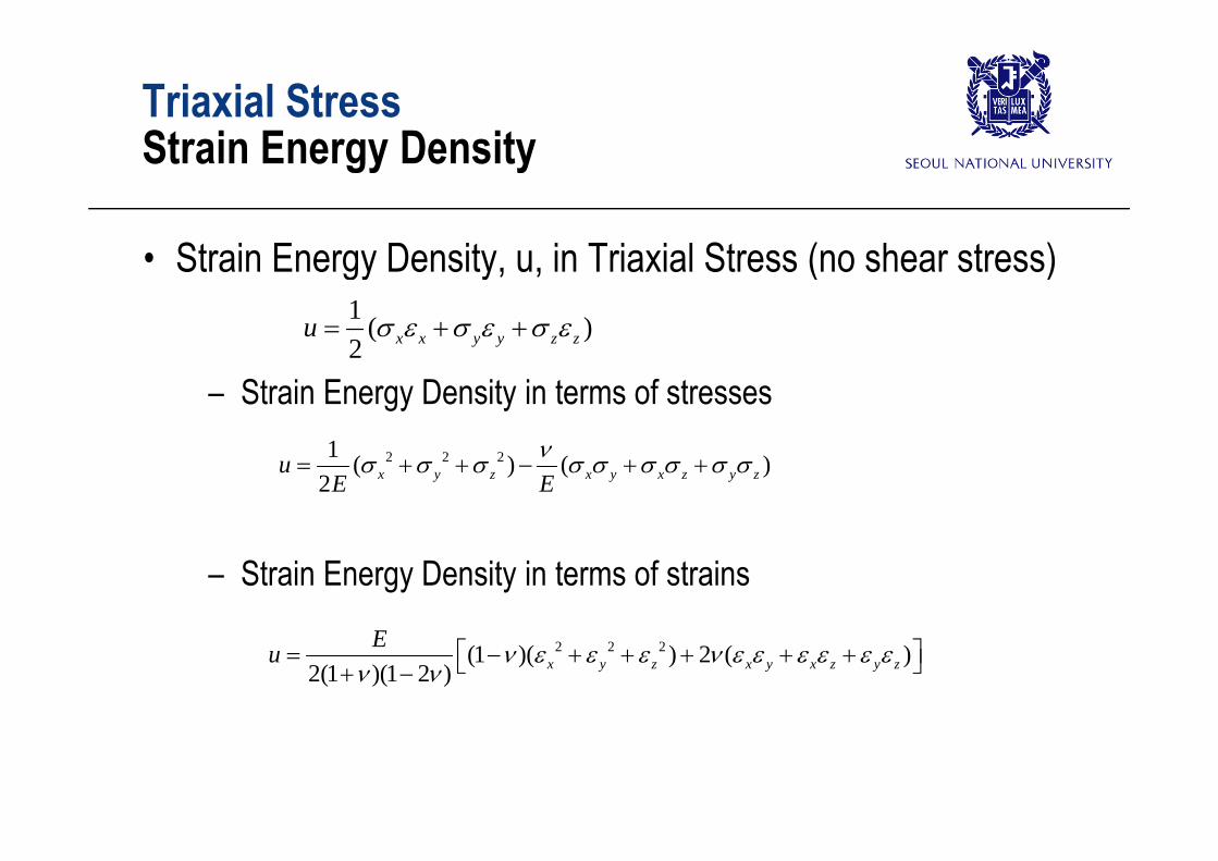
Triaxial StressSt i E D itStrain Energy Density
• Strain Energy Density, u, in Triaxial Stress (no shear stress)1 ( )u
– Strain Energy Density in terms of stresses
( )2 x x y y z zu
2 2 21 ( ) ( )2 x y z x y x z y zuE E
– Strain Energy Density in terms of strains
2 2 2(1 )( ) 2 ( )2(1 )(1 2 ) x y z x y x z y z
Eu
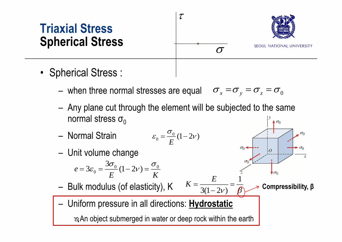
Triaxial StressS h i l St
Spherical Stress
• Spherical Stress : – when three normal stresses are equal 0x y z when three normal stresses are equal– Any plane cut through the element will be subjected to the same
normal stress σ0
0x y z
normal stress σ0
– Normal Strain 00 (1 2 )
E
– Unit volume change0 0
033 (1 2 )eE K
1– Bulk modulus (of elasticity), K
Uniform pressure in all directions: Hydrostatic
E K 13(1 2 )
EK
Compressibility, β
– Uniform pressure in all directions: HydrostaticAn object submerged in water or deep rock within the earth
Plane Strain
Outline
• Introduction• Plane Stress• Plane Stress• Principal Stresses and Maximum Shear Stresses• Mohr’s Circle for Plane Stress
H k ’ L f Pl St• Hooke’s Law for Plane Stress• Triaxial Stress• Plane Strain