1 Mechanics of Granular Materials (MGM) Experiment Flight Hazard Analysis and Safety Compliance Data Laboratory for Atmospheric and Space Physics University of Colorado at Boulder September 20, 2000
Transcript
1
Mechanics of Granular Materials
(MGM)
Experiment Flight Hazard Analysisand
Safety Compliance Data
Laboratory for Atmospheric and Space PhysicsUniversity of Colorado at Boulder
September 20, 2000
2
EXECUTIVE SUMMARY
The enclosed report and associated documents represent the Safety Compliance Data Package (SCDP)for the Mechanics of Granular Materials (MGM) Experiment that has been manifested on STS-107 /SPACEHAB currently planned for June 2001. This mission is the third flight for MGM and willhereafter be identified as MGM-III. The first experiment, MGM-I, was flown on STS-79 / SPACEHAB/ MIR-04 in September 1996. This mission is presently considered for safety hazard reverificationpurposes to be the “baseline mission”. The second experiment was flown on STS-89 /SPACEHAB /MIR-08 in January 1998. The present report, "MGM Experiment Flight Hazard Analysis and SafetyCompliance Data," is based upon the same-titled report for MGM-I, which was authored by SandiaNational Laboratories (SNL) and the report for MGM-II, authored by the Laboratory for Atmosphericand Space Physics (LASP) of the University of Colorado at Boulder (UCB). The MGM-I experimenthardware, software, and auxiliary hardware were designed, built, and tested by SNL. Subsequent to theMGM-I flight in September 1996, responsibility for MGM missions has been assumed by LASP. Dr.Stein Sture is the MGM Principal Investigator (UCB) and Dr. Nicholas C. Costes is Co-Investigator(UCB). Marshall Space Flight Center (MSFC) continues in the role of NASA sponsorship andoverseeing the MGM program. Dr. Khalid Alshibli is the MGM Project Scientist(MSFC, UniversityAlabama Huntsville (UAH).)
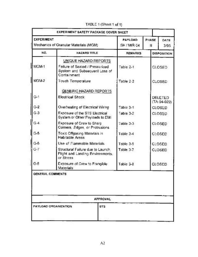
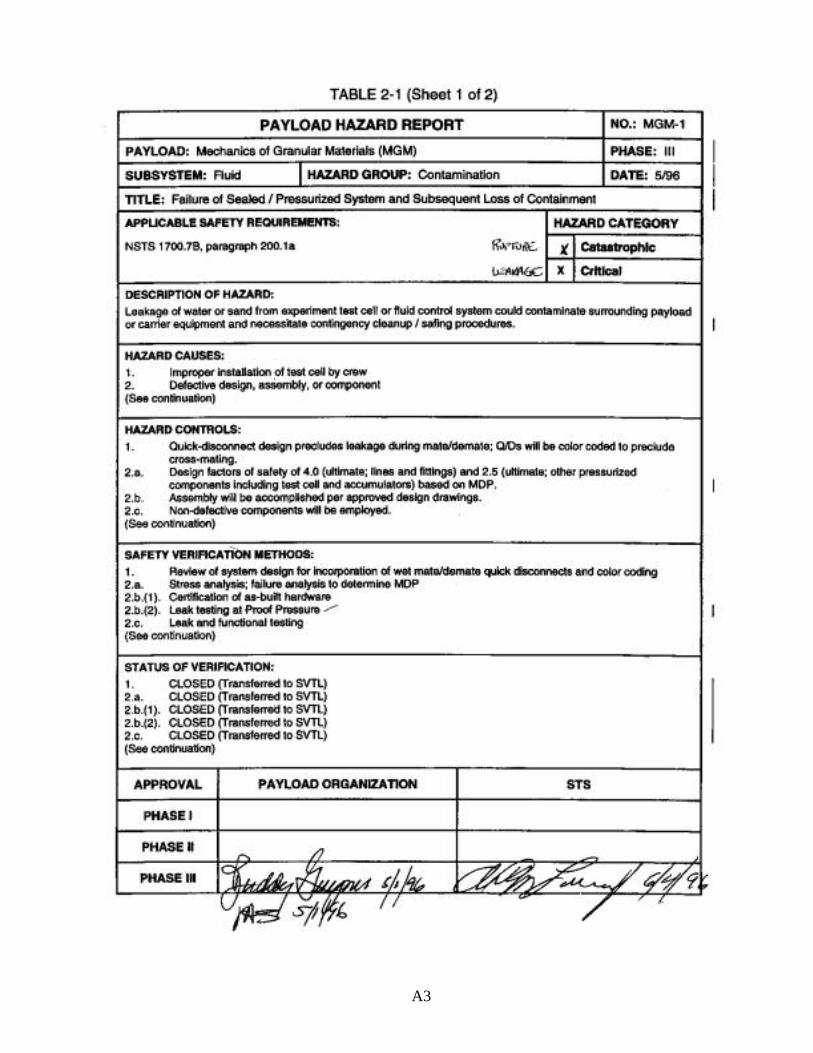
As was the case for the SCDP for the MGM-I and MGM-II missions, the present MGM-III reportauthored by UCB/LASP includes a narrative MGM description with illustrations in 6 sections coveringthe MGM Experiment Overview, Flight Hardware, Thermal Control System, On-Orbit Operations,Safety Assessment, and Hazard Analysis. The Hazard Analysis section of the SNL MGM-I reportincluded the detailed Payload Hazard Reports (PHRs), recorded on JSC 542B forms, for eachapplicable hazard in hazard groups defined by NSTS 1700.7B, paragraph 209.1. Since the STS-107mission is a reflight for MGM, the MGM-III flight hardware has been evaluated as series hardware inaccordance with Section 9 of NSTS 13830 REV C, items A through N. In place of PHRs, the MGM-IIIReflight Hazard Analysis comprising Section 6.0 of the present report submits the 'unique data forseries/reflown elements' by addressing the items A-N inclusive. Item E in 6-E provides an Assessmentof Verification Methods through the Hazard Control Reverification Status Matrix for MGM-III (SeriesHardware). Safety verification methods for each hazard item in Payload Hazard Reports of the baselinemission are tabulated to allow assessment of the status of corresponding MGM-III safety reverificationitems and monitoring their submittal to the Safety Verification Tracking Log.
3
TABLE OF CONTENTS
TABLE OF CONTENTS 3
1.0 MGM EXPERIMENT OVERVIEW 8
2.0 MGM FLIGHT HARDWARE 9
2.1 General 9
2.2 Twin Double-Locker Assembly 9
2.3 Test Cell 9
2.4 Fluid Control System 16
2.5 Payload General Support Computer (PGSC) 19
2.6 Combined Electronics Unit (CEU) 19
2.7 Sample Imaging and Video Data Storage 21
3.0 MGM THERMAL CONTROL SYSTEM 21
4.0 MGM ON-ORBIT OPERATIONS 21
5.0 MGM SAFETY ASSESSMENT 26
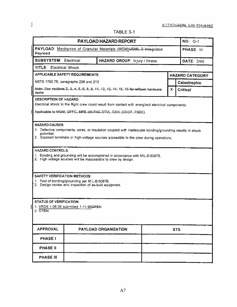
5.1 Electrical Shock 26
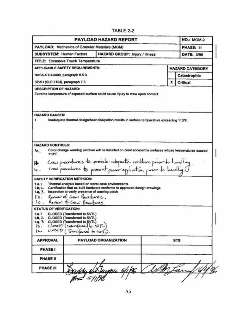
5.2 Touch Temperature 26
5.3 Emergency Module Egress 26
5.4 Smoke Detection/Fire Suppression 26
5.5 Rotating Equipment 26
5.6 Materials Selection 27
5.7 Frangible Materials 27
5.8 Rupture of Test Cell or Fluid System Components 27
Table 3. New drawings submitted for MGM-III STS-107 34
Table 4. Hazard Control Reverification Status Matrix for MGM-III (Series Hardware) 36-38
7
LIST OF ACRONYMS
A/D Analog-to-DigitalCCD Charge-Coupled DeviceCCTV Closed-Circuit TelevisionCEU Combined Electronics UnitDC Direct CurrentDP Differential PressureEEPROM Electrically Erasable Programmable Read Only MemoryEMI Electro-Magnetic InterferenceES Embedded SystemJSC Johnson Space CenterkPa Kilo-PascalPHR Payload Hazard ReportLASP Laboratory for Atmospheric and Space PhysicsLED Light-Emitting DiodeMDP Maximum Design PressureMGM Mechanics of Granular Materialsmm millimeterµ micro-meterMUA Material Usage AgreementMSFC Marshall Space Flight CenterNDE Non-Destructive EvaluationNSTS National Space Transportation SystemP1 Water Jacket Absolute Pressure SensorPGSC Payload General Support ComputerPIP Power Interface PanelPRV Pressure Relief Valvepsia pounds per square inch absolutepsid pounds per square inch differentialpsig pounds per square inch gaugeQD Quick-DisconnectRAM Random-Access MemoryS/MM Shuttle/MIR MissionSTS Space Transportation SystemSVTL Safety Verification Tracking LogTDLA Twin Double-Locker AssemblyUCB University of Colorado at BoulderUI User InterfaceVDC Volts Direct CurrentVSU Video Switching Unit
8
MECHANICS OF GRANULAR MATERIALS
1.0 MGM EXPERIMENT OVERVIEW
The Mechanics of Granular Materials (MGM) experiment is designed to study the behavior ofcohesionless granular materials at low confining pressures in a microgravity environment.Quantification of material constitutive behavior such as load-deformation, stress-strain, instabilityand failure modes, and ultimate strength will advance the understanding of interactions between solidparticles and interstitial fluids. These interactions can contribute to catastrophic events in geologicgranular material deposits, such as landslides, dam failures, soil liquefaction caused by earthquakesor wave action, and land erosion.
The MGM-III flight experiment will consist of 9 displacement-controlled, axial compression /extension tests performed at very low differential confining pressures (< 0.075 psid) on rightcylindrical specimens of approximately 75 mm diameter and 150 mm in length. Test specimensconsisting of solid granular particles enclosed in a thin, linearly elastic latex membrane are preparedunder controlled compaction methods and environmental conditions. The specimens are watersaturated, with the interstitial water kept at 2 psig pressure. Each end of the specimen incorporates arigid circular platen by which axial loading is applied. The specimen is enclosed in a larger, water-filled prismatoid, which is pressurized at approximately 15 psig during transportation and storage.The cell is reduced in pressure to provide low differential confining pressure during on-orbitexperiment operations. The combined specimen / prismatoid plus associated sensors, cables andconnectors, etc., comprise a “test cell”. The 9 experiments will be performed on 3 separate, butessentially identical, test cells during the STS-107 mission. Each test cell will be re-used twice, for atotal of 3 experiments per test cell. The ninth experiment will not be completed, but instead saved in are-used, pre-test configuration for post-flight examination.
The Phase III Flight Safety Review for the first and second flights of MGM were held on May 9-10,1996 and September 16, 1997, respectively. There were no action items levied against MGM-I orMGM-II by the Phase III Flight Safety Review Panel, and both were considered to be safe for flight.
A series of nine displacement-controlled triaxial compression experiments were performed in theSPACEHAB module of the Orbiter, during STS-79 and STS-89 missions to MIR. The experimentswere conducted on a total of nine right cylindrical specimens 75 mm in diameter and 150 mm inlength at confining pressures ranging from 0.189 psi to 0.007 psi (1.30 kPa to 0.05 kPa) at relativedensities of 85% (STS-79) and 65% (STS-89). The displacement-controlled test configuration waschosen to maintain overall specimen-apparatus stability as well as local material stability in the eventof continuous or discontinuous bifurcation instability. All MGM-I and MGM-II experimental testcells, axial load testing, fluid pressure control, and data recording elements performed such thatscientific return was 100% for the overall missions.
In-flight anomalies on STS-79 occurred during the deactivation phase of both the first and thirdexperiments, and a hardware grounding anomaly was noted post-flight. In-flight anomalies alsooccurred on STS-89 during one experiment. None of these anomalies had any impact on safety orscience, as described in detail in Section 6-I, where resolution of the anomalies to prevent recurrenceon the presently manifested mission is also presented. For safety reverification of MGM flighthardware and experimental procedures for the STS-107 reflight mission, STS-79 (MGM-I) isconsidered the baseline mission.
9
2.0 MGM FLIGHT HARDWARE
2.1 General
MGM hardware is composed of two double-locker assemblies that provide structuralsupport and equipment mounting. For the first MGM-I flight on S/MM-04 the twindouble lockers held three test cell assemblies during ascent, descent, and in on-orbitstorage before and after experiment runs. This was also the case for MGM-II /SPACEHAB / S/MM-08. However, three additional test cells were flown and carried inseparate SPACEHAB stowage. For MGM-III on STS-107 the three test cells will all becarried in separate SPACEHAB stowage. Each test cell consists of a test sample, sampleconfinement, compressing mechanism, plus associated sensors, cables, and connectors.Experiment operations are controlled by internal microprocessors and operated though auser-interface on an external computer. Additionally, MGM has three locker-mountedCCD video cameras, whose signals are multiplexed and interface with an externalcamcorder. This allows for recording the sample displacement and deformation asrevealed by motion of grid patterns printed on the elastic latex membrane.
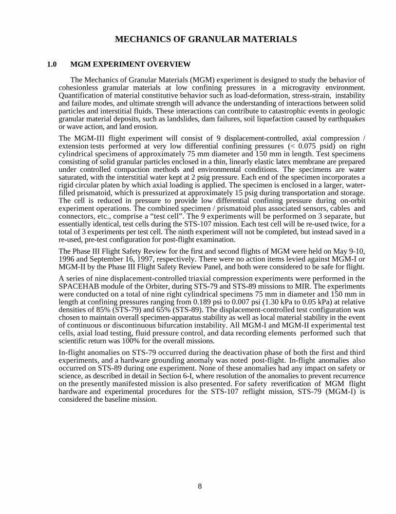
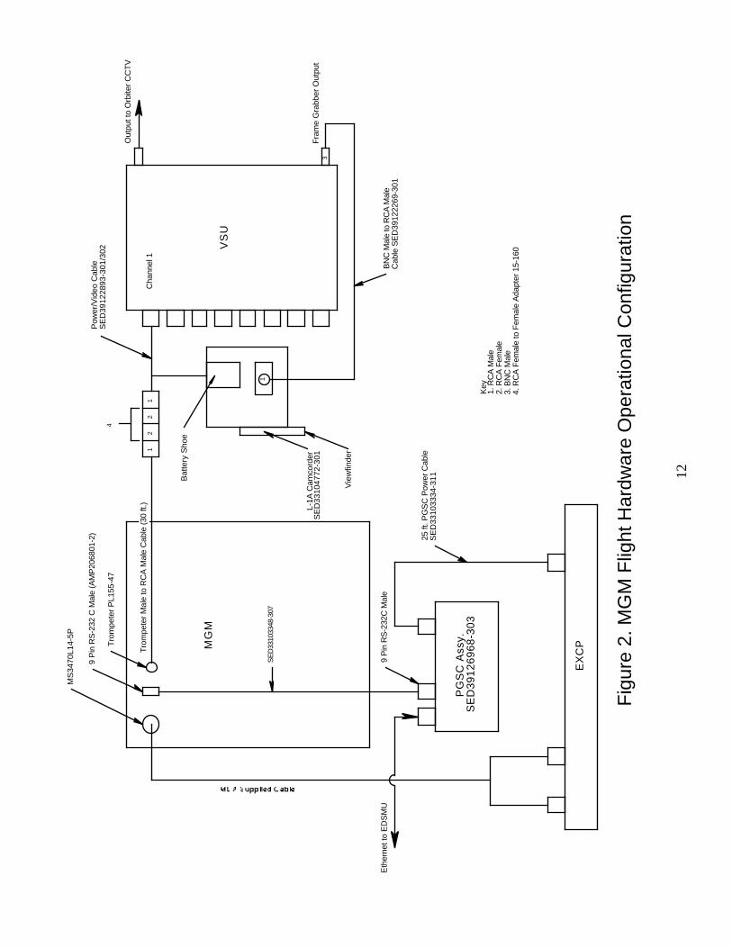
MGM hardware has been designed for compatibility with the Orbiter Middeck as well asthe SPACEHAB module. For STS-107, MGM-III will be mounted on the aft bulkheadof the SPACEHAB module. The experiment utilizes a self-contained viewing stage intowhich experiment test cells are inserted on orbit for testing. MGM video cameras arepre-adjusted so that additional focusing and alignment are not required. An STS-provided Payload General Support Computer (PGSC) provides the crew interface to theexperiment control system. New to MGM, telemetry (both commanding and data) willalso be used on STS-107. An STS-provided camcorder records video data to documenttest results. An experiment system functional block diagram is shown in Figure 1. Flighthardware operational configuration is illustrated schematically in Figure 2. The followingparagraphs provide further hardware description.
2.2 Twin Double-Locker Assembly
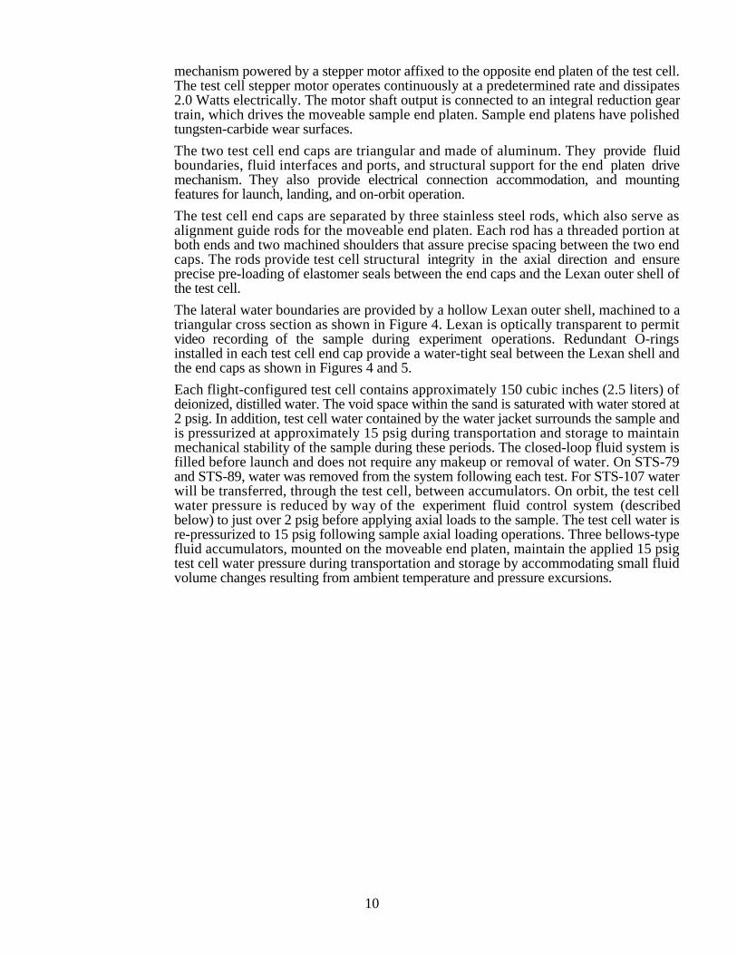
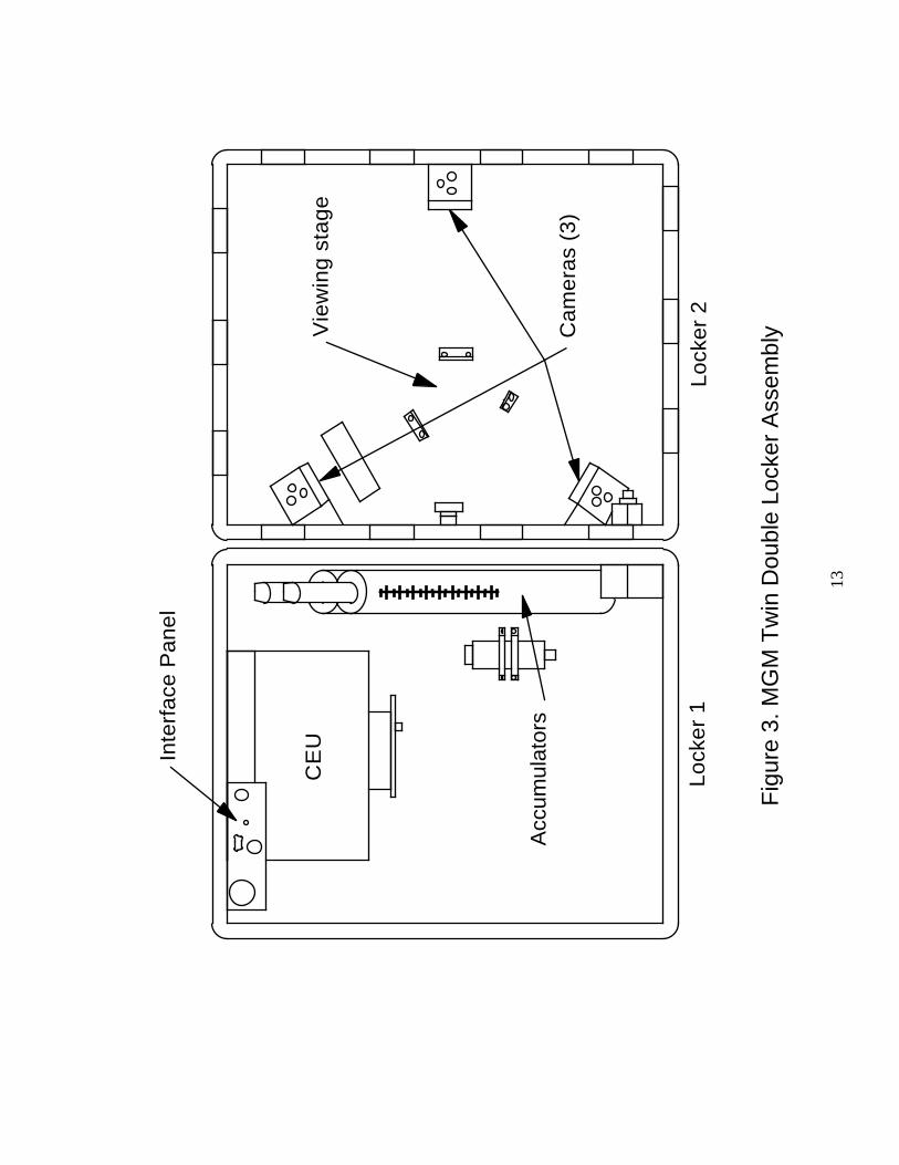
The Twin Double-Locker Assembly (TDLA) and test cell comprises the heart of theMGM flight hardware. The TDLA consists of two horizontally adjacent, aluminumdouble locker structures as illustrated in Figure 3. The locker structures interface with theSPACEHAB aft bulkhead by way of double experiment mounting plates that areprovided by SPACEHAB. The TDLA incorporates integral mounting / stowageprovisions for most MGM experiment components. Three stowage drawers are requiredfor storage of three test cells and miscellaneous small items.
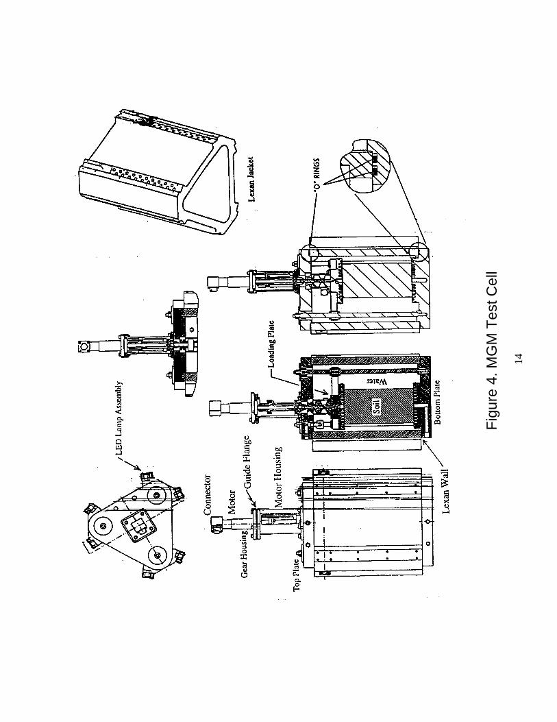
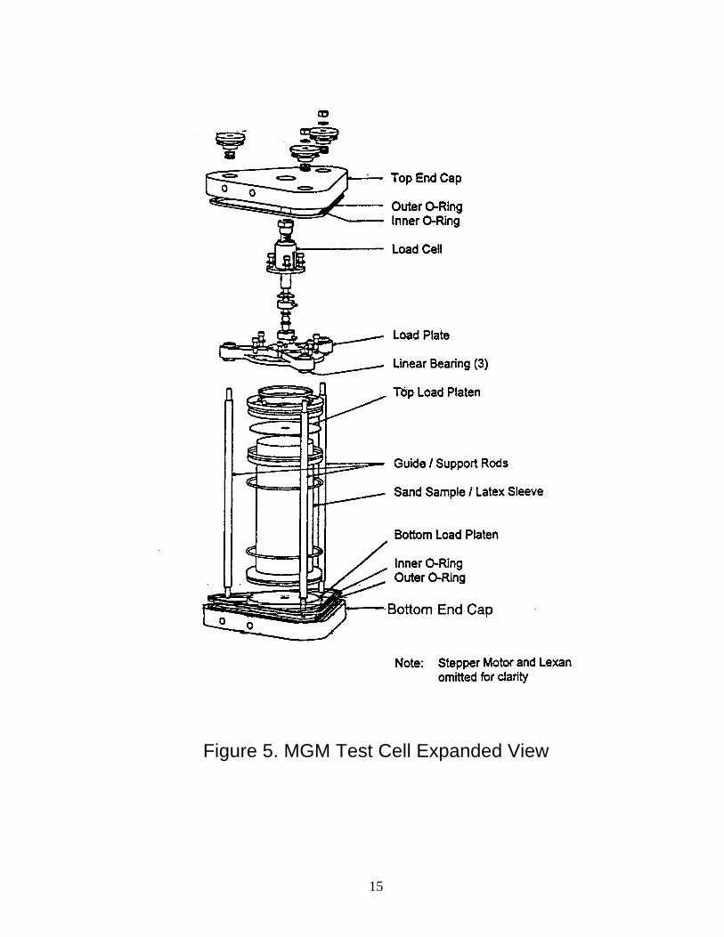
2.3 Test Cell
The test cell is a water-filled prismatoid of triangular cross section that contains theexperiment sample and compressing mechanism. Figures 4 and 5 present several viewsand details of the test cell. The sample consists of “Ottawa F-75 Silica” sand, auniformly sized (0.2 ± 0.1 mm) granular material, pre-tumbled with particles smallerthan US Sieve No. 200 (i.e., smaller than 0.074 mm) removed. The sand is tumbled,washed and dried before being closely packed, using a standardized dry pluviationtechnique, into a 75 mm diameter by 150 mm tall cylindrical mold that holds and shapesthe latex sleeve. A vacuum is applied allowing release of the mold, and the sample(including the latex sleeve) is installed in the test cell between circular end platens, one ofwhich is fixed and the other moveable. The outside of the test cell is then assembledaround the specimen, filled with water and pressurized, confining the sand and allowingthe release of the vacuum. The internal voids in the sand are then filled with water. (Onprevious missions, the voids contained only air.) The fixed platen is integral with one ofthe test cell end caps. The moveable platen is driven axially by means of a lead screw
10
mechanism powered by a stepper motor affixed to the opposite end platen of the test cell.The test cell stepper motor operates continuously at a predetermined rate and dissipates2.0 Watts electrically. The motor shaft output is connected to an integral reduction geartrain, which drives the moveable sample end platen. Sample end platens have polishedtungsten-carbide wear surfaces.
The two test cell end caps are triangular and made of aluminum. They provide fluidboundaries, fluid interfaces and ports, and structural support for the end platen drivemechanism. They also provide electrical connection accommodation, and mountingfeatures for launch, landing, and on-orbit operation.
The test cell end caps are separated by three stainless steel rods, which also serve asalignment guide rods for the moveable end platen. Each rod has a threaded portion atboth ends and two machined shoulders that assure precise spacing between the two endcaps. The rods provide test cell structural integrity in the axial direction and ensureprecise pre-loading of elastomer seals between the end caps and the Lexan outer shell ofthe test cell.
The lateral water boundaries are provided by a hollow Lexan outer shell, machined to atriangular cross section as shown in Figure 4. Lexan is optically transparent to permitvideo recording of the sample during experiment operations. Redundant O-ringsinstalled in each test cell end cap provide a water-tight seal between the Lexan shell andthe end caps as shown in Figures 4 and 5.
Each flight-configured test cell contains approximately 150 cubic inches (2.5 liters) ofdeionized, distilled water. The void space within the sand is saturated with water stored at2 psig. In addition, test cell water contained by the water jacket surrounds the sample andis pressurized at approximately 15 psig during transportation and storage to maintainmechanical stability of the sample during these periods. The closed-loop fluid system isfilled before launch and does not require any makeup or removal of water. On STS-79and STS-89, water was removed from the system following each test. For STS-107 waterwill be transferred, through the test cell, between accumulators. On orbit, the test cellwater pressure is reduced by way of the experiment fluid control system (describedbelow) to just over 2 psig before applying axial loads to the sample. The test cell water isre-pressurized to 15 psig following sample axial loading operations. Three bellows-typefluid accumulators, mounted on the moveable end platen, maintain the applied 15 psigtest cell water pressure during transportation and storage by accommodating small fluidvolume changes resulting from ambient temperature and pressure excursions.
11
PG
SC
(ST
S-P
RO
VID
ED
)L1
A C
AM
CO
RD
ER
(ST
S-P
RO
VID
ED
)
EN
VIR
ON
ME
NT
AL
SE
NS
OR
S
PO
WE
R C
ON
VE
RS
ION
& T
RA
NS
IEN
T S
UP
PR
ES
SIO
NM
AS
TE
R &
SLA
VE
MIC
RO
CO
NT
RO
LLE
RS
ST
EP
PE
R M
OT
OR
CO
NT
RO
LLE
RS
& D
RIV
ER
S
VID
EO
CO
NT
RO
LLE
RS
SIG
NA
L C
ON
DIT
ION
ING
& A
/D C
ON
VE
RS
ION
ME
MO
RY
CA
RD
INT
ER
FA
CE
S
CO
MB
INE
D E
LE
CT
RO
NIC
S U
NIT
(C
EU
)
FLA
SH
CA
RD
DA
TA
ST
OR
AG
E
MG
M T
WIN
DO
UB
LE
LO
CK
ER
AS
SE
MB
LY
(T
DL
A)
FLU
ID C
ON
TR
OL
SY
ST
EM
3-C
AM
ER
A V
IDE
O IM
AG
ING
SY
ST
EM
TIM
E D
ISP
LAY
SY
ST
EM
SE
NS
OR
SS
PE
CIM
EN
TE
ST
CE
LL
PH
OT
O L
ED
S
Fig
ure
1. M
GM
Sys
tem
Fun
ctio
nal B
lock
Dia
gram
12
Out
put t
o O
rbite
r C
CT
V
12
21
VS
U
BN
C M
ale
to R
CA
Mal
eC
able
SE
D39
1222
69-3
01
Key
1. R
CA
Mal
e2.
RC
A F
emal
e3.
BN
C M
ale
4. R
CA
Fem
ale
to F
emal
e A
dapt
er 1
5-16
0
Vie
wfin
der
Bat
tery
Sho
e
Fra
me
Gra
bber
Out
put
Pow
er/V
ideo
Cab
leS
ED
3912
2893
-301
/302
Cha
nnel
1
3
1
4
PG
SC
Ass
y.S
ED
39
12
69
68
-30
3
Eth
erne
t to
ED
SM
U
9 P
in R
S-2
32 C
Mal
e (A
MP
2068
01-2
)
MS
3470
L14-
5P
Tro
mpe
ter
PL1
55-4
7
MG
M
SE
D33
1033
48-3
07
Tro
mpe
ter
Mal
e to
RC
A M
ale
Cab
le (
30 ft
.)
25 ft
. PG
SC
Pow
er C
able
SE
D33
1033
34-3
11
L-1A
Cam
cord
erS
ED
3310
4772
-301
9 P
in R
S-2
32C
Mal
e
EX
CP
Fig
ure
2. M
GM
Flig
ht H
ardw
are
Ope
ratio
nal C
onfig
urat
ion
13
Lock
er 2
Cam
eras
(3)
Vie
win
g s
tag
eC
EUInte
rfac
e P
anel
Lock
er 1
Acc
umul
ator
s
Fig
ure
3. M
GM
Tw
in D
oubl
e Lo
cker
Ass
embl
y
14
Fig
ure
4. M
GM
Tes
t Cel
l
15
Figure 5. MGM Test Cell Expanded View
16
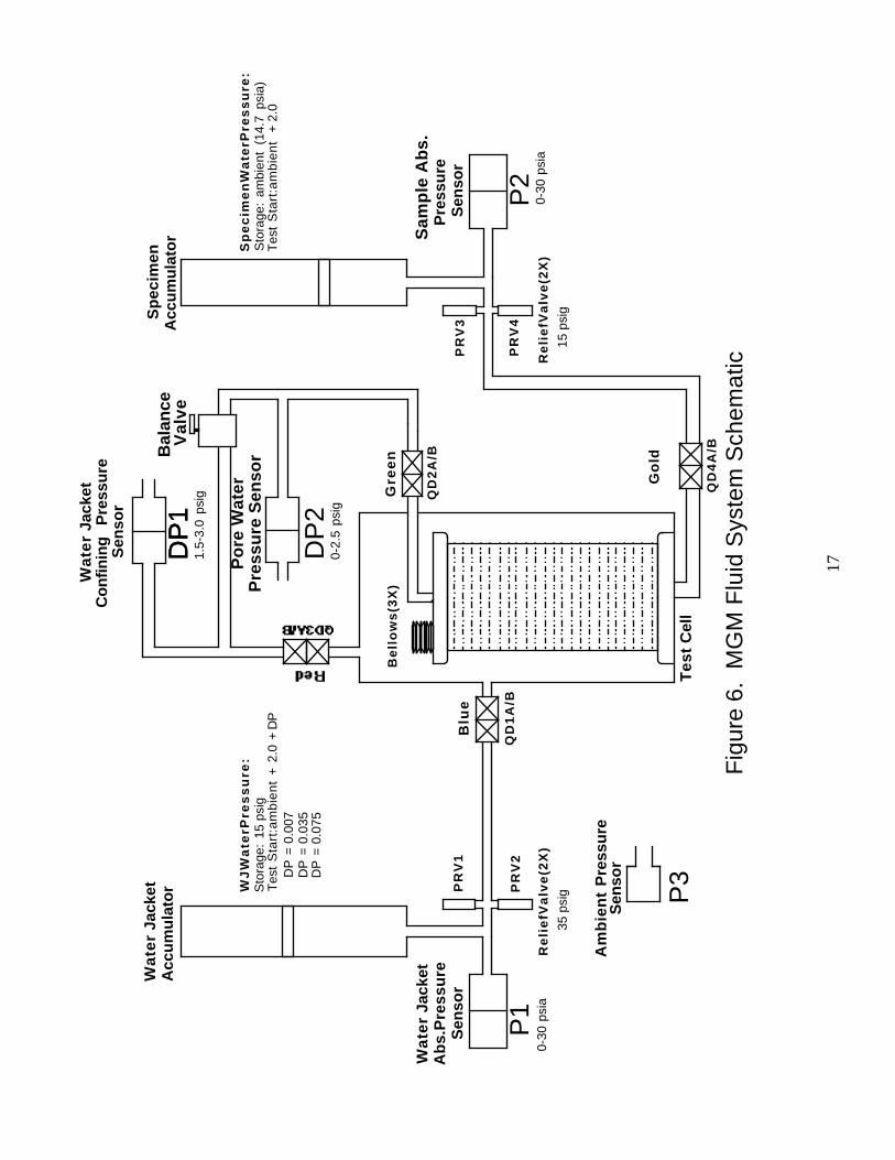
2.4 Fluid Control System
The MGM Fluid Control System, depicted schematically in Figure 6, is a closed-loopsystem that regulates both the test cell water jacket pressure and the specimen fluidpressure before, during, and after on-orbit axial loading operations. It interfaces witheach test cell by means of low-loss quick-disconnects.
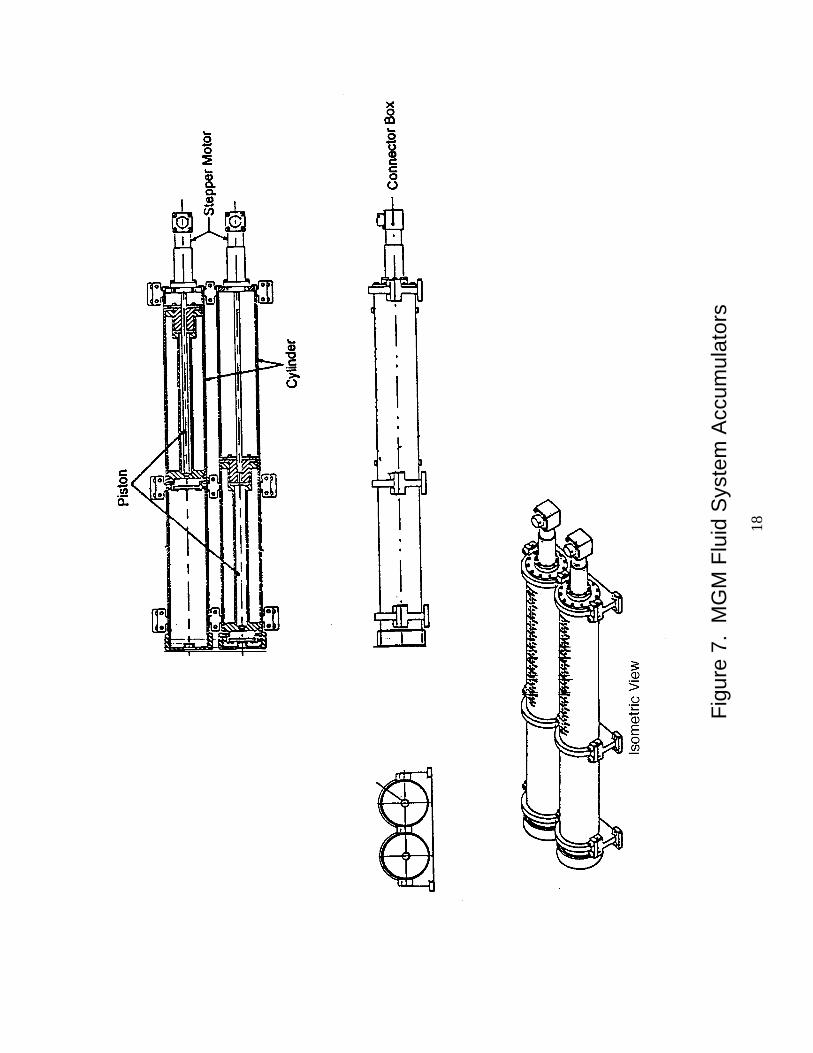
Water pressure control is accomplished with two electronically controlled piston-typefluid accumulators, illustrated in Figure 7. Each accumulator piston is driven by a steppermotor that operates at a nominal 600 steps per second. The angular motor shaft rotationis 15° per step, and each motor dissipates 4.5 Watts electrically. The motor shaft outputis connected to an integral 360:1 reduction gear train, which drives the accumulatorpiston. Each accumulator stepper motor is driven independently as is required to produceor maintain the desired differential pressure between the water jacket and the test sample.
The water jacket accumulator, which initially contains only a small amount of water, isused to reduce test cell water jacket pressure before on-orbit testing. This isaccomplished by withdrawing water from the water jacket until the desired differentialtest pressure is achieved. That accumulator maintains the desired differential test pressure(under software control) as the sample is compressed during the test. At the end of thetest and before removal of the test cell, the water jacket pressure is raised to 15 psig bythe reverse process.
For STS-79 and STS-89 (MGM-I and MGM-II) the sample accumulator contained airsince all the specimens were tested under dry conditions. For MGM-III on the STS-107mission, the sand voids and corresponding sample accumulator contains water. Theaccumulator, stepper motor, and related hardware used for the sample is essentiallyidentical to the water jacket hardware, which has been proven safe when containing water.The specimen accumulator is used to regulate the interior water pressure of the sample at2 psig to help maintain the differential pressure between the sample interior water and theexterior water jacket. During drained tests, the sample accumulator moves to maintain the2 psig pressure. During undrained tests, the sample accumulator is initially positionedsuch that the sample pressure is 2 psig. During undrained specimen compression thisaccumulator does not move, allowing the specimen pressure to vary.
No water will need to be added or taken away from the accumulators during the mission.However, water will need to be transferred between accumulators. This will be performedusing the closed-loop system. When all four QDs are connected to the test cell thebalance valve can be opened to transfer water between water and specimen accumulators.In this process, the sample accumulator is moved in the appropriate direction, and P1, theabsolute pressure sensor corresponding to the water jacket accumulator, maintains a lowgauge pressure (16.7 psia), resulting in the water jacket accumulator moving at the samerate but in opposite direction and taking in the water from the sample accumulator.
Set point differential pressure regulation is implemented by experiment EmbeddedSystem (ES) control of the accumulator drive motors in response to inputs from absolutepressure sensors (P1 and P2) that monitor various system pressures, and vented pressuresensors (DP1 and DP2), which read the gauge pressures in the water jacket and the testsample. The difference between the gauge sensors is used to read the differentialpressure between the water jacket and the test sample. This arrangement is different fromSTS-79 and STS-89: previously, two differential pressure sensors directly read pressuredifference. The change included a change of sensors. The Tavis brand sensor (0-0.01psid) is replaced by a Lucas-Schaevits brand sensor (0-5 psig) which has the sameelectrical requirements. The Validyne sensor type was not replaced, though one pressureport is now open to the atmosphere to read gauge pressure, and the exchangeable sensingdiaphragm was replaced to change the sensing range.
17
Sp
ecim
enA
ccu
mu
lato
r Sam
ple
Ab
s.P
ress
ure
Sen
sor
Gre
en
QD
2A
/B
PR
V3
Sp
ec
ime
nW
ate
rPre
ss
ure
:S
tora
ge:
ambi
ent
(14.
7ps
ia)
Tes
tS
tart
:am
bie
nt
+ 2
.0
Re
lie
fVa
lve
(2X
)
P2
Bal
ance
Val
ve
Go
ld
QD
4A
/B
15 p
sig
PR
V4
0-30
psia
Wa
ter
Jack
etA
ccu
mu
lato
r
Wa
ter
Jack
etA
bs.
Pre
ssu
reS
enso
r
DP
=0.
007
DP
=0.
035
DP
=0.
075
Blu
e
Re
lie
fVa
lve
(2X
)
P3
Am
bie
nt
Pre
ssu
reS
enso
r
Tes
tC
ell
WJ
Wa
terP
res
su
re:
Sto
rage
:15
psi
gT
est
Sta
rt:a
mb
ien
t+
2.0
+ D
P
PR
V1
Be
llo
ws
(3X
)
QD
1A
/B
35 p
sig
0-30
psia
PR
V2
P1
1.5-
3.0
psig
0-2.
5ps
ig
DP
1D
P1
DP
1
DP
2
Po
re W
ater
Pre
ssu
re S
enso
r
Wa
ter
Jack
etC
on
finin
gP
ress
ure
Sen
sor
Fig
ure
6.M
GM
Flu
id S
yste
m S
chem
atic
18
Fig
ure
7.M
GM
Flu
id S
yste
m A
ccum
ulat
ors
19
2.5 Payload General Support Computer (PGSC)
The PGSC is an STS-provided, laptop computer using Windows operating system thatprovides the crew interface to the MGM ES. It processes and transmits user commands,receives and displays data from the experiment microcontrollers, requests crew inputswhen needed, and receives and displays advisory messages. MGM-provided software,consisting of object oriented code written in C++, is used toward this end. The PGSCwill also have an ethernet connection to provide downlink telemetry and receive uplinkfrom MGM ground software, written in LabVIEW.
2.6 Combined Electronics Unit (CEU)
The CEU provides experiment power, control, monitoring, and data management andstorage. MGM utilizes SPACEHAB-provided 28 VDC electrical power. Individual CEUcomponents are described in the following paragraphs.
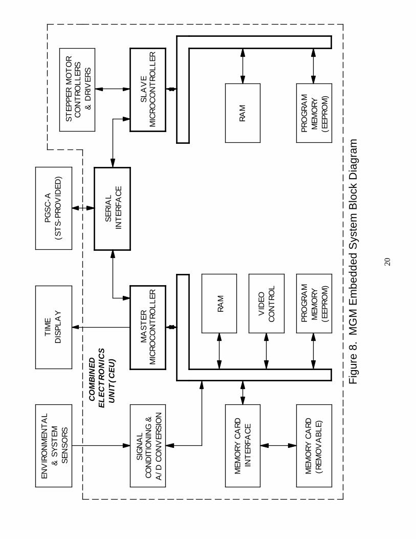
2.6.1 Master and Slave Microcontrollers (Embedded System or ES)
A block diagram illustrating the two embedded microcontrollers (80C196 family) andrelated interface, timing, and memory functions appears in Figure 8. Microcontrollersreceive commands from and transmit data / messages to the PGSC, control the samplestepper motor to achieve the specified load profile, control the Fluid Control Systemaccumulator motors to maintain the desired confining pressures, and format / store dataon “flash” memory cards. Microcontrollers use MGM-developed code written in C andAssembly Language and function as a slave to the PGSC-provided user interface. Thecode has been updated for the STS-107 experiment configuration.
2.6.2 Stepper Motor Controllers and Drivers
A stepper motor is an electromechanical device that converts electrical pulses intomechanical movements. The output shaft of a stepper motor rotates in discrete stepincrements when electrical pulses are applied to it in the proper sequence. The sequenceof the applied pulses is directly related to the direction of the shaft’s rotation. Therotation speed of the shaft is directly related to the frequency of the input pulses, and thetotal angular rotation is directly related to the number of input pulses applied.
Stepper motors with integral gear-reduction drives are used in the test cells and fluidsystem accumulators. Each test cell stepper motor and integral gear reduction providesthe drive mechanism to compress the test sample at a 35 mm per hour compression rate.Each accumulator stepper motor with a 360:1 gear reduction operating at a nominal 600steps per second drives the accumulator piston at a rate of 320 mm per hour. Steppermotor controllers and drivers function under the control of the MGM slavemicrocontroller. This provides properly conditioned and scaled inputs to the steppermotors that drive the Fluid Control System accumulators and the sample loadingmechanism.
20
ENV
IRO
NM
ENTA
L&
SYS
TEM
SEN
SORS
PRO
GRA
MM
EMO
RY(E
EPRO
M)
SERI
AL
INTER
FAC
E
SLA
VE
MIC
ROCO
NTR
OLL
ER
STEP
PER
MO
TO
RCO
NTR
OLL
ERS
& D
RIV
ERS
PGSC
-A(S
TS-
PRO
VID
ED)
MEM
ORY
CA
RDIN
TER
FAC
ERA
M
VID
EOCO
NTR
OL
PRO
GRA
MM
EMO
RY(E
EPRO
M)
MEM
ORY
CA
RD(R
EMO
VA
BLE)
MA
STER
MIC
ROCO
NTR
OLL
ER
COM
BIN
ED
ELECTRONIC
SUNIT
(CEU)
RAM
SIG
NA
LCO
ND
ITIO
NIN
G &
A/D
CO
NV
ERSI
ON
TIM
ED
ISPL
AY
Fig
ure
8.M
GM
Em
bedd
ed S
yste
m B
lock
Dia
gram
21
2.6.3 Power Conversion and Transient Suppression
The power converter provides conditioned DC power at the proper voltage levels to theexperiment electronics assemblies. It also provides voltage and current limiting, transientsuppression, and circuit protection consistent with Memo TA-92-038. Each DC-to-DCconverter incorporates a temperature sensor that monitors the respective converter boardtemperature and provides a signal to the CEU, which can shut off the experiment if thereis thermal overload. A block diagram of the experiment power distribution is shown inFigure 9.
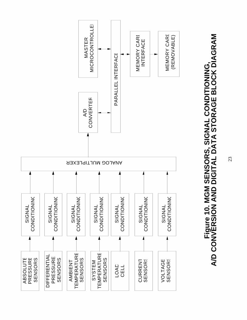
2.6.4 Sensors, Signal Conditioning, and A/D Conversion
A block diagram of the MGM sensors, signal conditioning, A/D conversion, andmemory card interface is shown in Figure 10.
2.7 Sample Imaging and Video Data Storage
Video photography is performed on orbit using three experiment-provided CCD videocameras, which provide 360-degree video coverage around the cylindrical sand sample.The three locker-mounted cameras view the sample through the Lexan sleeve at 120-degree angular separation, recording displacement and deformation of the sample asregistered on 3 grid patterns printed on the latex membrane. Multiplexing circuitryintegral to the MGM electronics permits storage of video data from all three cameras ona STS-provided L1A camcorder, which is manually started before the test and continuesto run until the test is complete. Illumination of the test sample for imaging andvideotaping activities is provided by six linear arrays of light-emitting diodes (LEDs)mounted at the corners of the test cell Lexan jacket.
3.0 MGM THERMAL CONTROL SYSTEM
Thermal analysis has determined that MGM can rely on internal thermal mass and naturalambient air movement for thermal control. That analysis is part of the Verification Data Packageand, therefore, is not included here.
4.0 MGM ON-ORBIT OPERATIONS
MGM is not powered during pre-launch, ascent, or descent phases of the mission. On-orbit crewprocedures are detailed in SPACEHAB Experiment Operations Checklist MGM, documentMDC2000W5808.
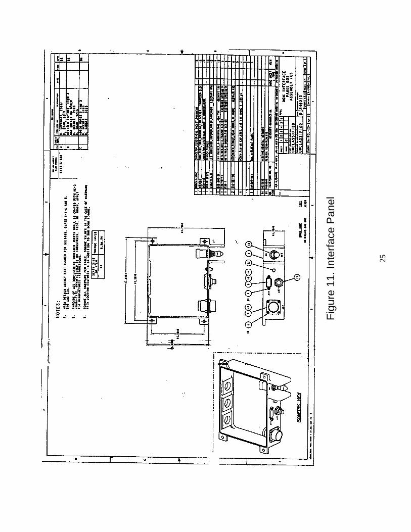
Experiment operations begin with the crew attaching the PGSC cable to the MGM InterfacePanel and ethernet cable from the PGSC to the EDSMU for command and telemetry. TheMGM input power cable and output video cable are connected to the MGM before launch. TheMGM Interface Panel is illustrated in Figure 11.
The Beta Cloth light-blocking fabric screen is removed from the right-hand double locker ThePGSC and L1 camcorder are removed from stowage and configured. One of the three MGMtest cells in SPACEHAB stowage is selected and installed in the right-hand double lockerviewing stage, and connected to the experiment electrical system by mating three electricalconnectors.
22
+5
V
+/-
12
V
DC
/DC
Conv
erte
rs
1A
1A
1A
1A
+/-
5V
Con
trol
and
Dat
aA
quis
itio
nEl
ectr
onic
s
Line
Filt
er
Line
Filt
er
Line
Filt
er+
28
V
Step
per
Mot
or
Com
bin
ed
Ele
ctr
onic
sUnit
(CEU)
+5
CN
TRL
+2
8
MGM
Mai
n Po
wer
Swit
ch a
nd1
0A
CB
28
VD
C f
rom
Spac
eHab
28
VD
C f
rom
Spa
ceH
abPG
SC
3A
3A
Com
pute
r-co
ntro
lled
Pow
erIn
terr
upt
Mot
orD
rive
rs
Step
per
Mot
or
Step
per
Mot
or
Fig
ure
9.M
GM
Pow
er D
istr
ibut
ion
Blo
ck D
iagr
am
23
Fig
ure
10.
MG
M S
EN
SO
RS
, SIG
NA
L C
ON
DIT
ION
ING
,A
/D C
ON
VE
RS
ION
AN
D D
IGIT
AL
DA
TA
ST
OR
AG
E B
LO
CK
DIA
GR
AM
AB
SO
LU
TE
PR
ES
SU
RE
SE
NS
OR
S
DIF
FE
RE
NT
IAL
PR
ES
SU
RE
SE
NS
OR
S
AM
BIE
NT
TE
MP
ER
AT
UR
ES
EN
SO
RS
SY
ST
EM
TE
MP
ER
AT
UR
ES
EN
SO
RS
LO
AD
CE
LL
CU
RR
EN
TS
EN
SO
RS
VO
LT
AG
ES
EN
SO
RS
SIG
NA
LC
ON
DIT
ION
ING
SIG
NA
LC
ON
DIT
ION
ING
SIG
NA
LC
ON
DIT
ION
ING
SIG
NA
LC
ON
DIT
ION
ING
SIG
NA
LC
ON
DIT
ION
ING
SIG
NA
LC
ON
DIT
ION
ING
SIG
NA
LC
ON
DIT
ION
ING
ANALOG MULTIPLEXER
A/D
CO
NV
ER
TE
RM
AS
TE
RM
ICR
OC
ON
TR
OL
LE
R
PA
RA
LL
EL
IN
TE
RF
AC
E
ME
MO
RY
CA
RD
INT
ER
FA
CE
ME
MO
RY
CA
RD
(RE
MO
VA
BL
E)
24
The electrical assemblies are powered on. User Interface (UI) software is opened in the PGSC.The crew then initiates an automated self-test to verify proper interconnection and operation ofthe experiment apparatus. Steps are performed to initiate the system, including setting the METand identifying the test cell. The test cell is connected to the experiment fluid system by matingtwo quick-disconnects. The video image is checked to verify operation of the cameras andmultiplexing, and video recording is manually initiated.
The desired experiment protocol is initiated by the crew through the PGSC. The ES decreasespressure inside the test cell water jacket to approximately 3 psi above ambient, and differentialpressure between the test cell water and the sample interior water is equalized by the ExperimentFluid System under control of the experiment microcontrollers acting as slaves to the PGSC.Two more fluid system quick-disconnects are mated and the ES decreases pressure inside thetest cell water jacket to slightly above 2 psi above ambient. During this sequence the balancevalve is temporarily opened for automatic sensor calibration. The Beta Cloth light-blockingfabric screen that covers the right-hand double locker is reattached with Velcro, and theexperiment begins. The crew checks on the progress of the experiment at 15 minute intervals.Following the experiment stage 1 of a 2-part reformation procedure (for specimen re-use) isinitiated. Stage 2 is performed during setup of the next test. Three tests will be performed oneach test cell.
Upon completion of the third experiment on a single test cell, the fabric screen is removed fromthe front of the right side double locker. Through the UI, pressure in the test cell is raisedslightly and two fluid system quick-disconnect is demated. The pressure is then raised to 15 psigstorage pressure. The remaining two fluid system quick-disconnects are demated. The system isthen powered off and all applicable electrical interfaces are disconnected. Between tests on thesame test cell, the equipment will be powered off, but pressures will not be raised to 15 psig andfluid and electrical lines to the test cell will not be removed. As a result, the connection of fluidlines will not be performed at the beginning of the two subsequent tests on a test cell. [Note:Water from the water jacket accumulator is transferred to the sample accumulator through thebalance valve following two of the nine experiments.]
Applicable portions of the above sequence are repeated for successive test cell protocols.Experiment electrical apparatus is powered down between runs. Following the third test of a testcell, the test cell is restowed. The PGSC and camcorder may be restowed between experimentsand are restowed following final experiment deactivation.
25
Fig
ure
11. I
nter
face
Pan
el
26
5.0 MGM SAFETY ASSESSMENT
MGM experiment hardware and flight operations comply with requirements of NSTS 1700.7B.STS-supplied items used in support of MGM are previously flown and flight qualified, and willbe used within the envelope of their accepted performance capabilities and qualification limits.Specific safety considerations relevant to MGM are summarized in the following paragraphs.These considerations reflect the safety issues specific to the present manifested MGM-IIImission on STS-107. They are the same as the assessed safety items for the STS-79 baselinemission since the reflight hardware is essentially identical to the MGM-I hardware.
5.1 Electrical Shock
MGM electronics utilize low voltage (≤ 28 VDC) power. All energized conductors andcomponents are enclosed, insulated, or otherwise isolated to preclude crew contact.Accessible conductive surfaces are electrically bonded to a grounded structure inaccordance with MIL-B-5087B. MGM circuit protection complies with the requirementsof Memo TA-92-038. The Payload Safety Review Panel has established policy (TA-94-029) which eliminates the need for a Payload Hazard Report on Electrical Shock forincidental contact with voltages less than 32 VDC.
5.2 Touch Temperature
Color-changing indicators visually identify crew-accessible surfaces whose temperaturescan exceed 49 °C (120 °F). The indicator surfaces are located on the test cell andpressure accumulator stepper motors. The motors also incorporate thermistors thatprovide continuous temperature monitoring on the PGSC display.
5.3 Emergency Module Egress
Each flight-configured MGM test cell weighs approximately 30 lb. Test cells are stowedwhen not in use. One test cell is clamped in Locker 2 viewing stage during use andbetween subsequent tests. Test cells, however, are not considered to be penetrators, asdetermined from Figure 3-27 of the SPACEHAB Experiment Interface DefinitionDocument, dated October 1994, using MGM Test Cell weight of 37 pounds andminimum perimeter of 23.4 inches. That determination is documented in AnalysisVerification Report, MGM-AN-2.04.10.
5.4 Smoke Detection/Fire Suppression
Smoke detection for MGM powered equipment is provided by smoke detectors in theSPACEHAB cabin air loop. The MGM Combined Electronics Unit is constructed withaluminum that will not sustain a flame and does not have any penetrations that couldallow flame to propagate.
5.5 Rotating Equipment
MGM rotating equipment includes stepper motors used for sample compression andfluid accumulators. Rotating equipment is configured to preclude crew access. Rotatingcomponents are low-speed, low-mass, low-power items that are considered exempt fromformal assessment in accordance with JSC Memo TA-94-05.
27
5.6 Materials Selection
Wherever possible, MGM nonmetallic materials have been selected in accordance withMSFC-HDBK-527. In cases where MGM uses materials whose composition is eitherunknown or not “A”-rated, Material Usage Agreements (MUAs) have been prepared.Metallic materials used in structural applications have been selected in accordance withMSFC-SPEC-522. All material usage will be approved and certified by the MSFCMaterials and Processes Laboratory.
5.7 Frangible Materials
Frangible materials are associated only with the video camera lenses that are protectedwith shatterproof Lexan covers.
5.8 Rupture of Test Cell or Fluid System Components
Rupture of the test cell or Experiment Fluid System components could release distilledwater and possibly sand into the SPACEHAB module necessitating unplanned cleanupactivity. The test cell, however, is leak-before-burst design. Maximum normal test cellinternal pressure is approximately 15 psig (transportation and storage). Three bellows-type fluid pressure regulators mounted inside each test cell accommodate fluid expansion/ contraction due to changes in ambient temperature and limit corresponding pressureexcursions.
Four mechanical pressure relief valves are installed in the plumbing and set and tested toopen at 35 psig on the water jacket accumulator loop and 15 psig on the sampleaccumulator loop to further prevent pressure buildup. A vent rate analysis has shownthat, in the event of a very smart failure mode in which the water jacket accumulatorstepper motor drives the accumulator piston at a rate of 320 mm per hour, the vent rate is0.5 cubic inches per minute, or approximately 4 fluid ounces (118 cc) in the 15-minuteintervals during which the experiment is unattended by the crew.
The Experiment Fluid System has limited potential to over-pressurize the test cell. Themotor-driven water jacket accumulator is initially nearly empty, and the bellows-type testcell fluid pressure regulators can accommodate small volume changes without significantpressure increase. The volume of the sand sample increases (up to 18 percent maximum)during the axial loading operation, so the major possibility of exceeding intended test cellpressure occurs during the sample compression operation. As the volume of the sandsample increases, the differential pressure of the confining water jacket would increaserapidly if water were not withdrawn by the water jacket accumulator. However, as thedifferential pressure of the confining water jacket increases, the compressive strength ofthe sand sample rises approximately 8 times as rapidly, and stalls the compressingstepper motor very quickly before the confining water jacket pressure exceedsapproximately 14 psid. During the compression, the sample expands, and water must bemoved into the sample in order to prevent a decrease in pressure. As a result, potential tooverpressure the sample fluid system is limited. However, if such a case were to occur,the latex membrane separating the water jacket and fluid systems within the test cellwould expand and the water jacket system would control the pressure of both the waterjacket and sample. As a result, the bellows and other safety mechanisms in the waterjacket fluid system would also apply to the sample fluid system.
The Experiment Fluid System incorporates absolute and vented pressure sensors and anembedded microcontroller system that removes (via the embedded microcontroller)power to accumulator and sample compression stepper drive motors if water jacketaccumulator or test cell pressure exceeds approximately 35 psia or if the specimenaccumulator exceeds approximately 27 psia. [Note: The PGSC serves as a “watchdog”
28
to the embedded microcontroller by monitoring response to a health status query at fixedintervals; lack of a response results in a PGSC-initiated removal of power from all threestepper motors.]
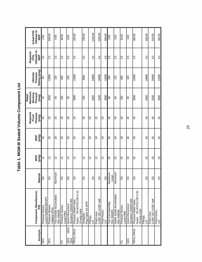
Pressurized components have been designed to factors of safety of 4.0 (lines/fittings)and 2.5 (other pressurized components) based on ultimate allowable and maximumdesign pressure (MDP), as listed in Table 1. As illustrated in Figure 6, the MGM FluidSystem has two main branches and a third fine-sensing branch: 1) componentsconnected to P1 (includes water jacket accumulator, pressure relief valves PRV1 andPRV2, lines, fittings, and quick-disconnect QD1); 2) components connected to P2(includes sample water accumulator, pressure relief valves PRV3 and PRV4, lines,fittings, and quick -disconnect QD2); 3) vented pressure sensors DP1 and DP2, lines,fittings, quick-disconnects QD3 and QD4, and balance valve). The fine-sensing branchwill be considered part of the main branch of components connected to P2 for pressure,safety, and verification purposes.
The MDP of components connected to P2 is 20 psig, as listed in Table 1, which is drivenby the maximum allowable common line pressure for differential pressure gauges DP1and DP2. Since DP1 and DP2 are capable of sensing extremely small (<0.01 psid)gauge pressures, they cannot withstand common line pressures above 20 psig withoutpermanent damage to the sensor diaphragm and subsequent loss of calibration. Forproof test purposes, therefore, the MDP of all components connected to DP1 and DP2(and hence, P2 as during testing they are interconnected through the sample side of thetest cell) is 20 psig. This is a change from STS-79 and STS-89, where the MDP was 40psig. To adjust for the lower MDP, PRV 3 and 4 and microcontroller monitoringresponse were adjusted accordingly.
The MDP of components connected to P1 is 40 psig, which is derived from the nominalvalue of the pressure relief valves (35 psig) and allows for some tolerance in openingpressures of those valves. Table 1 gives a list of the approved Maximum DesignPressures for the various components. There is no change from STS-79 for thesecomponents.
The MGM-III flight hardware for STS-107 is series hardware with no new modificationsimpacting safety since S/MM-04 (STS-79/MIR-04) and S/MM-08 (STS-89/MIR-08). ForMGM-III hardware reverification purposes the STS-79 mission is considered as the baselinemission and Payload Hazard Reports from STS-79 will be used. Any anomalies / changesresulting from the STS-89 flight will be assessed before flight on the STS-107 mission.
The hazards associated with the MGM hardware are controlled through design and byeliminating the hazards or by reducing them to an acceptable risk level.
For the present manifested mission, the MGM-III flight hardware has been evaluated as serieshardware in accordance with paragraph 216 of NSTS 1700.7 and section 9 of NSTS 13830REV C, items A through N inclusive. The verification methods from STS-79 have been reviewedand found to be acceptable. A reverification status matrix is provided to identify safetyverification requirements / methods for the baseline mission as recorded in the STS-79 PayloadHazard Reports, and corresponding safety reverification requirements for the reflight of MGM.
A. Identification of all series/reflown payloads, payload elements, and GSE to beused and the baseline safety analyses by document number, title, and releasedate. If chemicals are used, provide a new list, even though the chemicals are thesame as those used previously.
The baseline safety analysis (MGM-I, STS-79/MIR-04) for STS-107 safety is“Mechanics of Granular Materials (MGM) Experiment Flight Hazard Analysis andSafety Compliance Data” authored by Sandia National Laboratories, Albuquerque, NewMexico and submitted March 28, 1996. A description of the MGM-I hardware andPayload Hazard Reports can be found in the MGM Flight Hazard Analysis and SafetyCompliance Data for STS-79/MIR-04 that is on file at JSC. The MGM-IIIseries/reflight elements for the SPACEHAB module are described in Section 2 of thisdocument and include 3 experiment test cells, the Twin Double Locker Assembly(TDLA) that houses the pressure control system and associated plumbing, and videocameras during flight ascent and descent. During STS-107 ascent / descent the 3 MGM-III test cells will be carried in separate SPACEHAB stowage and remain there on-orbitexcept during experimentation in the MGM test locker.
B. Assessment of each series/reflown payload, payload elements, and GSE toindicate that the proposed use is the same as that currently approved (analyzedand documented).
The usage of all MGM-III reflight elements during STS-107 will, apart from details inon-orbit experimental protocol, be identical to usage of the MGM-I elements forexperiments performed on the STS-79 baseline mission.
C. New or revised hazard reports, additional data, and identification of hazardreports that are no longer applicable based on the reflight application.Identification and assessment of changes in hardware/software and operationsthat have any safety impact, including on-orbit verifications/ reverification ofhazard controls.
The verification methods from the STS-79 hazard reports were assessed for adequacyand validity and were found to be acceptable for controlling the hazards identified;therefore, no new hazard reports are required. Minor changes pertinent to PHR MGM-1
31
do exist and are described below. In brief, these changes do not affect or decrease theapplicability of hazard controls and verification methods.
Below are descriptions of changes to the hardware, software, and operations of theMGM equipment for STS-107.
Specimen Fluid Change
The fluid in the specimen and associated plumbing has been changed from air tode-ionized de-aired water. The water is from the same source as the water used inthe water jacket and associated plumbing, which was approved for use in STS-79and STS-89. Pressure release valves were added to the specimen-associatedplumbing to account for this change (described separately below.)
Undrained Testing Added
A new test capability has been added to MGM-III for STS-107. Previousexperiments have all been “drained,” where both internal specimen and externalwater jacket pressures are controlled during experimentation. During the new“undrained” testing, the internal specimen volume will be controlled and theexternal water jacket pressure will be controlled. Other aspects of the experimentperform the same in both drained and undrained experiments. This protocol is anew combination of system capabilities: No new core functions have been addedto the system.
Reforming Procedure Added
A new reforming procedure has been added to re-use specimens. After anexperiment, the top platen will be raised back to the initial position, and anamount of water (approximately 25-50 cc) will be pushed into the specimen fromthe sample accumulator. The extraneous water (approximately 25 cc) will then betransferred back to the sample accumulator. This protocol is a new combinationof system capabilities: No new core functions have been added to the system.
Quick-Disconnect Filter Change
The filter size inside the quick-disconnects has been changed from 10 micron to17 micron. The filter is the same type, with the only change being the micronsize.
Quick-Disconnect Addition
A fourth QD has been added to the TDLA and test cells. The QD is the samepart number as the current QDs, with exception to the color/keying (the QDscome in different colors and keyings, to avoid accidental mismating.) The nipple-side of the QD is added to the lower sample port on the test cells. The coupling-side of the QD is added on a direct line from DP2.
Dummy Connector Addition
A dummy connector to stow the coupling-side of the fourth QD during ascentand descent is added to Locker 2 in the TDLA. The dummy connector is thesame as the original 3 dummy connectors, with exception to the color coding.
Balance Valve Addition
A Swagelok brand plug valve (part number SS-4P4T) has been added to theplumbing associated with the specimen accumulator. It has been added to theMGM-III Sealed Volume Component List. The balance valve has analyzed anddoes not change the MDP or proof pressure of the system.
32
Pressure Sensor Modification
Pressure sensor DP1 (Validyne DP15) has been modified. The interchangeablediaphragm which determines the sensing range was replaced with one of thesame type, but wider range. The modification has no change on the pressurerating or electrical behavior of the sensor. Also, the pressure sensor is now usedas a gage sensor: one pressure port is connected to the water jacket pressure, theother is open to the shuttle environment. The sensor will be rechecked duringleak testing.
Pressure Sensor Exchange and MDP Decrease
Pressure transducer DP2 has been exchanged. The Tavis P108 has been replacedwith a Lucas Schaevitz PS10063-0004-5PV in order to increase the sensingrange. The new transducer is a gage sensor and is connected only to thespecimen plumbing and not the water jacket plumbing (as was the case in STS-79 and STS-89.) The new transducer was chosen because it has the same powerrequirements as the sensor it is replacing, and thus requires no electricalmodifications to be made. However, the ultimate pressure rating and ratedmaximum working pressure are lower for the new sensor (see Table *, below).This has been considered, and as its pressure ratings are the lowest of allcomponents in the sample-side plumbing it is now the controlling factor on theMDP for the specimen plumbing and in turn MDP for the specimen plumbingmust be lowered, equal to the MDP of the new sensor. The system has beenadjusted for proper functioning of the two-fault tolerant system: both the setpointcontrol via the embedded microprocessor and the crack point on pressure releasevalves for the sample plumbing are altered in response to this change. Thesample-side pressure that will prompt the embedded microprocessor to stop allmotors has been lowered to 10 psig, and the pressure at which the sample-sidePRVs will crack is 15 psig. As a result, the new MDP is 20 psig after allowingfor tolerance in opening pressures of those valves. Additionally, these checkswill be tested for proper functioning. Also, leak test reverification according tomethods in PHR MGM-1 will be performed on all plumbing systems (bothwater jacket and specimen) and the 3 test cells. No change has been made on thewater jacket plumbing, and thus the setpoint control via the embeddedmicroprocessor and the crack point on pressure release valves is unchanged forthat plumbing loop.
A new plumbing configuration is implemented with different pressure sensors,and newly added balance valve, pressure release valves and fourth QD. Theplumbing for STS-79 and STS-89 was as follows: The first plumbing groupconsisted of a water jacket accumulator was connected with an absolute pressuresensor and one QD, which connected to the water jacket side of the test cell. Thisplumbing was water-filled. A second plumbing group consisted of a sampleaccumulator connected with and absolute pressure sensor and two differentialpressure sensors and one QD, which connected to the sample side of the test cell.The plumbing was air-filled. A third plumbing group had connections to the
33
other side of the two differential pressure sensors and a QD, which connected tothe water jacket side of the test cell during low pressure situations.
The new plumbing for STS-107 is as follows: The first plumbing group is notaltered. The second plumbing group is filled with water, and the two differentialpressure sensors are removed and pressure release valves added. The thirdplumbing group is now divided into two halves, separated by a balance valve. Inone half, there is a QD which connects to the sample side of the test cell and agage pressure sensor. In the other half, there is another QD which connects to thewater jacket side of the test cell and another gage pressure sensor. This thirdplumbing group is connected to the test cell only during low pressure situations.This third plumbing group will be treated as part of the second plumbing groupfor safety verification, and are subject the proof pressures and MDP as thesecond plumbing group.
The items in Table 1. MGM-III Sealed Volume Component List reflect thismodification.
Software Change
The UI software has been updated from DOS to Windows 95/98. The UI,Master and Slave software has been updated to accommodate the new type ofexperiments. Command and telemetry functions have been added.
Pressure Release Valve Addition
Two pressure release valves (PRVs) were added to the specimen plumbing inresponse to the addition of water to the specimen. The valves are identical to thepressure release valves in the water jacket plumbing (Nupro SS-4CPA2-DR-3-15) with a different set crack pressure (15 psig.) The flow rate for the lower crackpressure is lower than for the Water Jacket Accumulator PRVs (1,2), but analysisindicates that the lower flow rate will still prevent the equipment from reachingthe MDP. It is noted that PHR MGM-1 indicates the use of only two PRVs: allfour PRVs will be subject to the same safety considerations as the two currentlycited in PHR MGM-1, however.
No Accumulator Purge Required
The accumulator purge sequence used on STS-79 and STS-89 will not berequired on STS-107. This step pushed water from the water jacket accumulatorinto a drink bag at the end of each experiment. Associated hardware (2 handles,drink bags) will not be included in MGM stowage. This sequence is replacedwith an accumulator reposition routine which allows the transfer of water fromthe specimen to water jacket accumulator while remaining fully contained withinthe TDLA plumbing. The process is also simpler for the crew; the descriptionwill replace previous purge procedures in the EOC, and the crew will be trainedaccordingly.
MGM PIP Modification
The RS232 serial cable internal to the MGM PIP has been modified so that theTDLA DCD signal is connected to the PGSC CTS signal. This allows hardwarehandshaking with the Windows program using a standard SPACEHAB RS232serial cable.
Analog to Digital Converter Modification
The MGM analog to digital converter card has been modified to optimize thescaling for pressure sensors DP1 and DP2. This change involved replacing sevenscaling resistors. The resistors are of the same model with different resistancevalue. These changes involve modifications to sensor signal circuitry only. Powerdistribution circuits were not affected.
34
Signal Conditioning Card Modification
The MGM signal conditioning card was modified to improve the stability ofsensors DP1 and DP2. This change involved replacing six resistors of samemodel with different resistance values. These changes involve modifications tosensor signal circuitry only. Power distribution circuits were not affected.
Bracket Exchange
The bracket which held DP2 (Tavis P108) for STS-79 and STS-89 will bechanged out with a new bracket to hold the new DP2 (Lucas Schaevitz PS10063-0004-5PV.) The new drawings have been submitted.
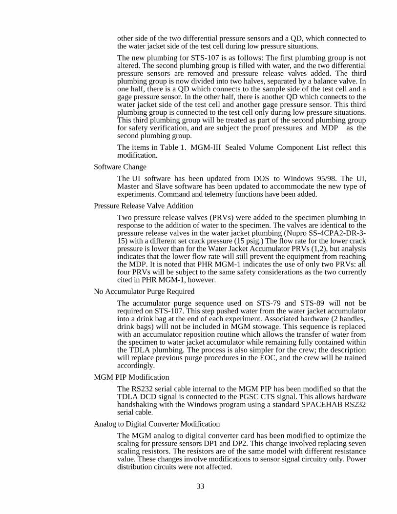
New Drawings
Four new drawings have been submitted for STS-107. They are listed in Table 2below.
Table 3. New drawings submitted for MGM-III STS-107.
Drawing Number Description
20540-1-0001 Bottom Bracket
20540-1-0002 Top Bracket
20540-1-0003 Valve Handle
20540-1-0004 Deflection Cap
Quantity of Memory Cards
Due to an increase in the number of experiments to be performed, 22 Flashmemory cards will be carried in stowage. For STS-79 and STS-89, 6 and 12memory cards were carried, respectively.
Quantity of Video Tapes
Due to an increase in the number of experiments to be performed and a changeof format in video cameras (digital), the number of video tapes used duringexperimentation will increase.
Offgasing
The TDLA will be tested for offgasing.
Test Cells Not Mounted in TDLA
No test cells will be mounted in the TDLA for ascent or descent on STS-107. Inresponse to this change, the procedures for removing the test cells from theTDLA will be removed and the ball driver used for this purpose will not beincluded in MGM stowage. The effect on structural analysis will be inspected.
D. A copy of the approved baselined phase III hazard reports (attachments notrequired).
The approved baseline phase III hazard reports for STS-79 are presented in Appendix A.
E. Report on the completion and results of applicable safety verifications.Submission of safety verification tracking log (JSC Form 764) that identifies allsafety verifications from the applicable baselined hazard reports that must be
35
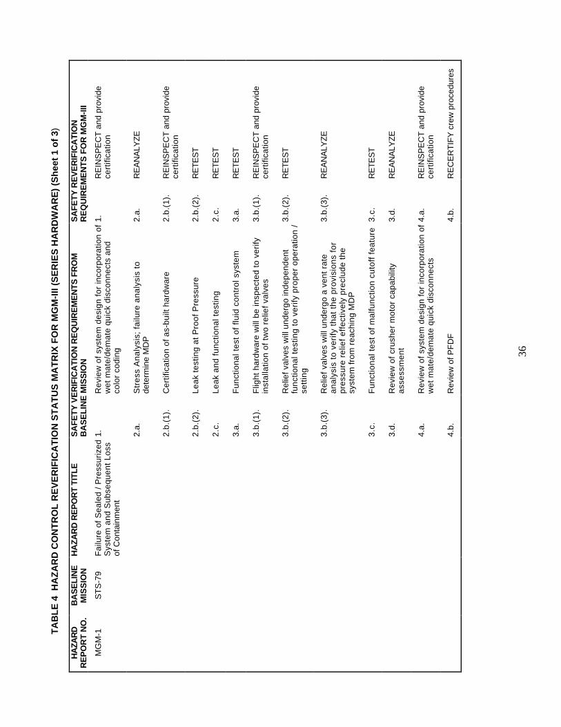
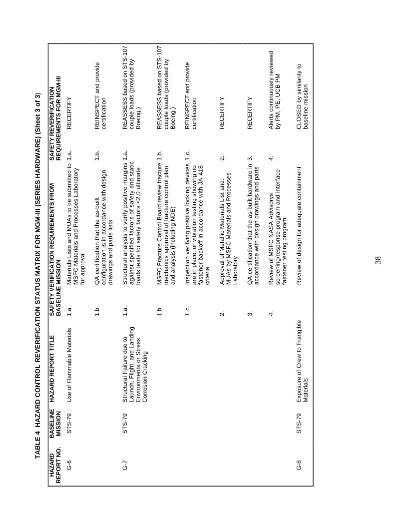
reverified for the reflight mission. In addition, open reverification from newhazard reports must be included as appropriate.
Table 3 presents the Flight Safety Reverification Status Matrix for the MGM-III payloadon STS-107 (Series Hardware) by listing the PHR Title and Safety Verification Methodsrecorded on each PHR documented in the Experiment Safety Data Package for flighthardware on the baseline mission that is on file at JSC. The current reverification statusfor each corresponding hazard item for MGM-III reflight on STS-107 is recorded forassessment of results and status monitoring for ultimate submittal to the SafetyVerification Tracking Log. All open verification issues will be transferred to the STS-107flight safety Verification Tracking Log (VTL) after the Phase III review is complete. Allsafety verifications to be completed for STS-107 are listed on the attached reverificationmatrix.
36
TA
BL
E 4
HA
ZA
RD
CO
NT
RO
L R
EV
ER
IFIC
AT
ION
ST
AT
US
MA
TR
IX F
OR
MG
M-I
II (S
ER
IES
HA
RD
WA
RE
) (S
hee
t 1
of
3)
HA
ZAR
DR
EP
OR
T N
O.
BA
SE
LIN
EM
ISS
ION
HA
ZA
RD
RE
PO
RT
TIT
LE
SA
FE
TY
VE
RIF
ICA
TIO
N R
EQ
UIR
EM
EN
TS
FR
OM
BA
SE
LIN
E M
ISS
ION
SA
FE
TY
RE
VE
RIF
ICA
TIO
NR
EQ
UIR
EM
EN
TS
FO
R M
GM
-III
MG
M-1
ST
S-7
9F
ailu
re o
f S
ea
led
/ P
ress
uri
zed
Sys
tem
an
d S
ub
seq
ue
nt
Lo
ssof
Con
tain
men
t
1.R
evi
ew
of
syst
em
de
sig
n f
or
inco
rpo
ratio
n o
fw
et
ma
te/d
em
ate
qu
ick
dis
con
ne
cts
an
dco
lor
cod
ing
1.R
EIN
SP
EC
T a
nd p
rovi
dece
rtifi
catio
n
2.a.
Str
ess
An
aly
sis;
fa
ilure
an
aly
sis
tode
term
ine
MD
P2.
a.R
EA
NA
LYZ
E
2.b
.(1
).C
ert
ifica
tion
of
as-
bu
ilt h
ard
wa
re2
.b.(
1).
RE
INS
PE
CT
and
pro
vide
cert
ifica
tion
2.b
.(2
).L
ea
k te
stin
g a
t P
roo
f P
ress
ure
2.b
.(2
).R
ET
ES
T
2.c
.L
ea
k a
nd
fu
nct
ion
al t
est
ing
2.c
.R
ET
ES
T
3.a.
Fu
nct
ion
al t
est
of
fluid
co
ntr
ol s
yste
m3.
a.R
ET
ES
T
3.b
.(1
).F
ligh
t h
ard
wa
re w
ill b
e in
spe
cte
d t
o v
eri
fyin
sta
llatio
n o
f tw
o r
elie
f va
lve
s3
.b.(
1).
RE
INS
PE
CT
and
pro
vide
cert
ifica
tion
3.b
.(2
).R
elie
f va
lve
s w
ill u
nd
erg
o in
de
pe
nd
en
tfu
nct
ion
al t
est
ing
to
ve
rify
pro
pe
r o
pe
ratio
n /
sett
ing
3.b
.(2
).R
ET
ES
T
3.b
.(3
).R
elie
f va
lve
s w
ill u
nd
erg
o a
ve
nt
rate
an
aly
sis
to v
eri
fy t
ha
t th
e p
rovi
sio
ns
for
pre
ssu
re r
elie
f e
ffe
ctiv
ely
pre
clu
de
th
esy
ste
m f
rom
re
ach
ing
MD
P
3.b
.(3
).R
EA
NA
LYZ
E
3.c
.F
un
ctio
na
l te
st o
f m
alfu
nct
ion
cu
toff
fe
atu
re3
.c.
RE
TE
ST
3.d.
Re
vie
w o
f cr
ush
er
mo
tor
cap
ab
ility
ass
ess
me
nt
3.d.
RE
AN
ALY
ZE
4.a.
Re
vie
w o
f sy
ste
m d
esi
gn
fo
r in
corp
ora
tion
of
we
t m
ate
/de
ma
te q
uic
k d
isco
nn
ect
s4.
a.R
EIN
SP
EC
T a
nd p
rovi
dece
rtifi
catio
n
4.b.
Rev
iew
of P
FD
F4.
b.R
EC
ER
TIF
Y c
rew
pro
cedu
res
37
TA
BL
E 4
HA
ZA
RD
CO
NT
RO
L R
EV
ER
IFIC
AT
ION
ST
AT
US
MA
TR
IX F
OR
MG
M-I
II (S
ER
IES
HA
RD
WA
RE
) (S
hee
t 2
of
3)
HA
ZAR
DR
EP
OR
T N
O.
BA
SE
LIN
EM
ISS
ION
HA
ZA
RD
RE
PO
RT
TIT
LE
SA
FE
TY
VE
RIF
ICA
TIO
N R
EQ
UIR
EM
EN
TS
FR
OM
BA
SE
LIN
E M
ISS
ION
SA
FE
TY
RE
VE
RIF
ICA
TIO
NR
EQ
UIR
EM
EN
TS
FO
R M
GM
-III
MG
M-2
ST
S-7
9E
xce
ssiv
e T
ou
ch T
em
pe
ratu
re1.
a.1
Th
erm
al a
na
lysi
s b
ase
d o
n w
ors
t-ca
seen
viro
nmen
ts1.
a.1
CL
OS
ED
by
sim
ilari
ty t
ob
ase
line
mis
sio
n
1.a.
2C
ert
ifica
tion
th
at
as-
bu
ilt h
ard
wa
re c
on
form
sto
ap
pro
ved
de
sig
n d
raw
ing
s1.
a.2
RE
INS
PE
CT
and
pro
vide
cert
ifica
tion
1.a.
3In
spe
ctio
n t
o v
eri
fy p
rese
nce
of
wa
rnin
gpa
tch
1.a.
3R
EIN
SP
EC
T a
nd p
rovi
dece
rtifi
catio
n
1.b.
Rev
iew
of
Cre
w P
roce
dure
s1.
b.R
EIN
SP
EC
T
1.c
.R
evie
w o
f C
rew
Pro
cedu
res
1.c
.R
EIN
SP
EC
T
G-1
ST
S-7
9E
lect
rica
l Sh
ock
—D
ELE
TE
D (
TA
-94-
029)
—D
ELE
TE
D (
TA
-94-
029)
G-2
ST
S-7
9O
verh
ea
ting
of
Ele
ctri
cal
Wiri
ng1.
a.C
ircu
it a
na
lysi
s1.
a.R
EA
SS
ES
wai
ver
1.b.
Insp
ect
ion
of
as-
bu
ilt h
ard
wa
re1.
b.R
EIN
SP
EC
T
G-3
ST
S-7
9E
xpo
sure
of
the
ST
S E
lect
rica
lS
yste
m o
f O
the
r P
ayl
oa
ds
toE
MI
1.T
est
fo
r ra
dia
ted
an
d c
on
du
cte
d e
mis
sio
ns
inac
cord
ance
with
MS
FC
SP
EC
-521
B1.
RE
AS
SE
S w
aive
r
G-4
ST
S-7
9E
xpo
sure
of
Cre
w t
o S
ha
rpC
orn
ers
, E
dg
es
or
Pro
tru
sio
ns
1.a.
Dra
win
g r
evi
ew
fo
r in
clu
sio
n o
f re
qu
ire
me
nts
to r
em
ove
sh
arp
co
rne
rs a
nd
ed
ge
s o
r to
pro
vid
e p
rote
ctiv
e c
ove
rs
1.a.
RE
INS
PE
CT
and
pro
vide
cert
ifica
tion
1.b.
QA
ce
rtifi
catio
n t
ha
t a
s-b
uilt
ha
rdw
are
con
form
s to
ap
pro
ved
dra
win
gs
1.b.
RE
INS
PE
CT
and
pro
vide
cert
ifica
tion
G-5
ST
S-7
9T
oxi
c O
ffg
asi
ng
in H
ab
itab
leA
reas
1.a.
Re
vie
w /
ap
pro
val o
f m
ate
ria
ls u
sag
e b
yM
SF
C M
ate
ria
ls a
nd
Pro
cess
es
La
bo
rato
ry1.
a.R
EC
ER
TIF
Y
1.b.
Ce
rtifi
catio
n t
ha
t a
s-b
uilt
co
nfig
ura
tion
is in
acc
ord
an
ce w
ith a
pp
rove
d d
esi
gn
dra
win
gs
an
d p
art
s lis
ts
1.b.
RE
CE
RT
IFY
1.c
.M
SF
C e
valu
atio
n /
ap
pro
val o
f o
ffg
as
test
data
1.c
.R
ET
ES
T a
nd p
rovi
dece
rtifi
catio
n
38
TA
BL
E 4
HA
ZA
RD
CO
NT
RO
L R
EV
ER
IFIC
AT
ION
ST
AT
US
MA
TR
IX F
OR
MG
M-I
II (S
ER
IES
HA
RD
WA
RE
) (S
hee
t 3
of
3)
HA
ZAR
DR
EP
OR
T N
O.
BA
SE
LIN
EM
ISS
ION
HA
ZA
RD
RE
PO
RT
TIT
LE
SA
FE
TY
VE
RIF
ICA
TIO
N R
EQ
UIR
EM
EN
TS
FR
OM
BA
SE
LIN
E M
ISS
ION
SA
FE
TY
RE
VE
RIF
ICA
TIO
NR
EQ
UIR
EM
EN
TS
FO
R M
GM
-III
G-6
ST
S-7
9U
se o
f Fla
mm
able
Mat
eria
ls1.
a.M
ate
ria
ls L
ists
an
d M
UA
s to
be
su
bm
itte
d t
oM
SF
C M
ate
ria
ls a
nd
Pro
cess
es
La
bo
rato
ryfo
r a
pp
rova
l
1.a.
RE
CE
RT
IFY
1.b.
QA
ce
rtifi
catio
n t
ha
t th
e a
s-b
uilt
con
figu
ratio
n is
in a
cco
rda
nce
with
de
sig
nd
raw
ing
s a
nd
pa
rts
lists
1.b.
RE
INS
PE
CT
and
pro
vide
cert
ifica
tion
G-7
ST
S-7
9S
tru
ctu
ral F
ailu
re d
ue
to
La
un
ch,
Flig
ht,
an
d L
an
din
gE
nvi
ron
me
nts
or
Str
ess
Cor
rosi
on C
rack
ing
1.a.
Str
uct
ura
l an
aly
sis
to v
eri
fy p
osi
tive
ma
rgin
sa
ga
inst
sp
eci
fied
fa
cto
rs o
f sa
fety
an
d s
tatic
loa
ds
test
s fo
r sa
fety
fa
cto
rs <
2.0
ulti
ma
te
1.a.
RE
AS
SE
SS
bas
ed o
n S
TS
-107
cou
ple
loa
ds
(pro
vid
ed
by
Boe
ing.
)
1.b.
MS
FC
Fra
ctu
re C
on
tro
l Bo
ard
re
vie
w f
ract
ure
me
cha
nic
s a
pp
rova
l of
fra
ctu
re c
on
tro
l pla
na
nd
an
aly
sis
(in
clu
din
g N
DE
)
1.b.
RE
AS
SE
SS
bas
ed o
n S
TS
-107
cou
ple
loa
ds
(pro
vid
ed
by
Boe
ing.
)
1.c
.In
spe
ctio
n v
eri
fyin
g p
osi
tive
lock
ing
de
vice
sa
re in
pla
ce,
or
vib
ratio
n t
est
ing
sh
ow
ing
no
fast
en
er
ba
cko
ff in
acc
ord
an
ce w
ith J
A-4
18
crite
ria
1.c
.R
EIN
SP
EC
T a
nd p
rovi
dece
rtifi
catio
n
2.A
pp
rova
l of
Me
talli
c M
ate
ria
ls L
ist
an
d.
MU
As
by
MS
FC
Ma
teri
als
an
d P
roce
sse
sLa
bora
tory
2.R
EC
ER
TIF
Y
3.Q
A c
ert
ifica
tion
th
at
the
as-
bu
ilt h
ard
wa
re in
acc
ord
an
ce w
ith d
esi
gn
dra
win
gs
an
d p
art
s3.
RE
CE
RT
IFY
4.R
evi
ew
of
MS
FC
NA
SA
Ad
viso
rys
scre
en
ing
/re
spo
nse
pro
gra
m a
nd
inte
rfa
cefa
ste
ne
r te
stin
g p
rog
ram
4.A
lert
s co
ntin
uo
usl
y re
vie
we
db
y P
M,
PE
, U
CB
PM
G-8
ST
S-7
9E
xpo
sure
of
Cre
w t
o F
ran
gib
leM
ater
ials
Re
vie
w o
f d
esi
gn
fo
r a
de
qu
ate
co
nta
inm
en
tC
LO
SE
D b
y si
mila
rity
to
ba
selin
e m
issi
on
39
F. Assessment of all noncompliances.
No safety deficiencies / noncompliances for MGM-III have been identified. There are nosafety waivers or deviations applicable to MGM-III.
G. Assessment of limited life items for reflown hardware.
PHR G-7 will be revisited due to the re-use of equipment, considering hardware lifetime.
Several o-rings are required in the MGM equipment, and the limited lifetime of o-ringsused in MGM-II would expire prior to the MGM-III launch date. For MGM-III, all o-rings were replaced with new o-rings. In addition, the Symetrics brand QDs were sent tothe manufacturer for replacement of internal o-rings, and the PRVs with internal o-ringswere replaced with identical new components.
H. Description of maintenance, structural inspections, and refurbishment ofreflown hardware and assessment of safety impact.
The MGM-III flight hardware for STS-107 is classified as series hardware. Activities forMGM-III hardware will include inspections, certifications, and other verificationprocedures to assure the safety, workmanship quality, and functionality of the MGM-IIIreflight hardware.
I. Assessment of all testing or ground/flight anomalies and failures previous usageof the series/reflown payload or payload element along with corrective actiontaken and rationale for continued use.
I.1
During the deactivation phase of MGM-I Experiment 1 on STS-79, an anomaly occurredduring execution of a new deactivation procedure made necessary by delays in otherscheduled crew activities. An omitted step in the procedure caused the water jacketaccumulator motor to run opposite to the expected direction, causing the pressure in thewater jacket system to increase. The pressure relief valves functioned properly, and asmall amount of water (<120 cc) was vented into MGM-I Locker-1 before the procedurewas halted. The Mission Specialist performing the procedure cleaned up the waterwithout incident. Post-flight investigation of the anomaly showed the MGM teamomitted the execution of a user-interface “Stop Motors” command that was believed tobe superfluous under the circumstances. This omission was in error, and caused theanomaly. The procedure has been corrected by adding the “Stop Motors” command.The corrected procedure will be used if a similar situation arises on the next flight.
I.2
During the deactivation phase of MGM-I Experiment 3, the water jacket absolutepressure sensor was observed to be producing erroneous readings. The sensor readingsfluctuated by 5-10 psi in response to very small (± 0.005 psi) changes in the actualpressure. The system depends on these readings during experiment deactivation tocontrol the two-step process in which the pressure in the test cells is raised from the testpressure first to 0.5 psid, then to the storage pressure of 15 psid. While the system wasable to raise the test cell pressure properly, the fluctuations in the sensor readings made it
40
difficult for the system to determine success and terminate the process. The process wasterminated manually with a software command. At the time of termination the test cellhad been returned to its final, stable storage condition. The remaining steps in thedeactivation procedure configure the TDLA for the following experiment. Since thisexperiment was the final MGM experiment of the mission, the MGM team decided toterminate the deactivation phase at that point.
For the MGM-II mission the water jacket absolute pressure sensor was producingerroneous readings. The readings fluctuated by 5 - 10 psi in response to very small(±0.005 psi) changes in actual pressure. The system depends on these readings duringexperiment activation and deactivation to control the pressure in the test cells. While thesystem was able to lower and raise the test cell pressure properly, the fluctuations in thesensor readings made it difficult for the system to determine success and terminate theprocess. The source of the anomaly has been identified to be a Symetrics quick-disconnect (QD) assembly. The sensor, which is connected on the plumbing between thewater jacket accumulator and the QD connecting the plumbing to the test cell, sensedmomentary increase in pressure when the accumulator is moved. The increase is sensedbecause the QD provides too much of a constriction of flow. The constriction is relatedto the small filter inside the QDs which are intended to prevent any objects in the test cell(such as sand grains) from entering the plumbing and the accumulator. The problem hasbeen corrected by replacing the 10-micron filter screens with a 17-micron filter.
I.3
During post-flight testing for MGM-I, McDonnell Douglas/SPACEHAB personnelperformed measurements indicating that the TDLA violated the single-point groundingscheme for the Orbiter 28V power. Measurements at UCB/LASP confirmed this. TheOrbiter 28V return and Orbiter chassis ground were connected in the MGM electronicsvia the Power Interface Panel (PIP). The cause was design error, rather than assemblyerror or malfunction. The verification inspection procedure performed at delivery did notinclude a check for this condition. Resolution of this anomaly has been achieved byreworking the PIP to enforce the required single-point grounding scheme for the nextmission.
I.4
For each experiment , science and engineering data are recorded on two memory cardswhich create a duplicate set that contains the same information on each card. After returnof the memory cards for MGM-II, the data was examined and it was detected that thememory card sets were not exact duplicates. Post-flight testing showed that the anomalywas caused by incomplete erasure of some of the cards. For STS-107 all memory cardswill be erased and checked before launch.
J. For flight reviews: a list of all pyrotechnic initiators installed or to be installedon the payload. The list will identify for each initiator the function to beperformed, the part number, the lot number and the serial number.
There are no pyrotechnic initiators or pressure vessels in the MGM-III hardware.
41
K. Ionizing and non-ionizing radiation forms for each source within the flighthardware or GSE.
There are no radiation sources or materials in the MGM-III reflight hardware.
L. For payloads that flew and were assessed for safety on either the shuttle or theISS and are being reflown on the other vehicle: Results of the assessment of thepayload with respect to the safety requirements of the new host vehicle (Flightsafety only: current versions of NSTS 1700.7 for the shuttle and the NSTS 1700.7ISS Addendum for the ISS).
Not applicable.
M. A final list of procedures for ground processing (ground only).
Not applicable.
N. Certificates of NSTS Payload Safety Compliance
Certificate of NSTS Payload Safety Compliance for Payload Design and FlightOperations to be submitted.
A1
APPENDIX A: BASELINE HAZARD REPORTS
This Appendix is a compilation of the Payload Hazard Reports and associated documents submitted bySandia National Laboratories in the Safety Compliance Data Package for MGM-I that was flown onSTS-79/SPACEHAB/MIR-04 in September 1996.