Ken Youssefi Mechanical Engineering Dept. 1 Mechanism Machines are mechanical devices used to accomplish work. A mechanism is a heart of a machine. It is the mechanical portion of the machine that has the function of transferring motion and forces from a power source to an output. Mechanism is a system of rigid elements (linkages) arranged and connected to transmit motion in a predetermined fashion. Mechanism consists of linkages and joints.
Transcript
Ken Youssefi Mechanical Engineering Dept. 1
MechanismMachines are mechanical devices used to accomplish work. A mechanism is a heart of a machine. It is the mechanical portion of the machine that has the function of transferring motion and forces from a power source to an output.
Mechanism is a system of rigid elements (linkages) arranged and connected to transmit motion in a predetermined fashion.
Mechanism consists of linkages and joints.
Ken Youssefi Mechanical Engineering Dept. 2
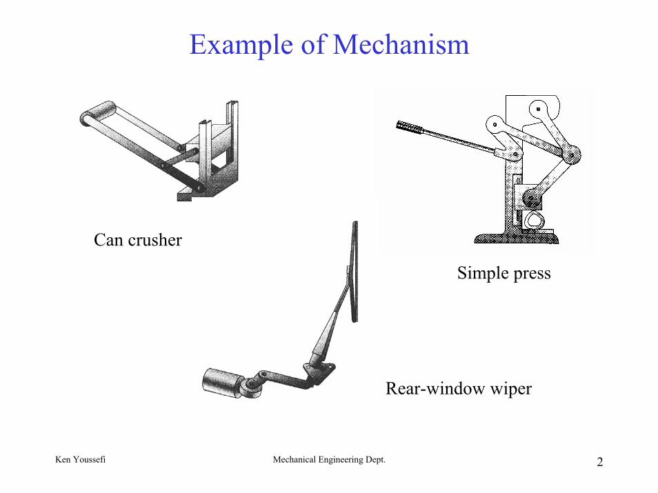
Example of Mechanism
Can crusher
Simple press
Rear-window wiper
Ken Youssefi Mechanical Engineering Dept. 3
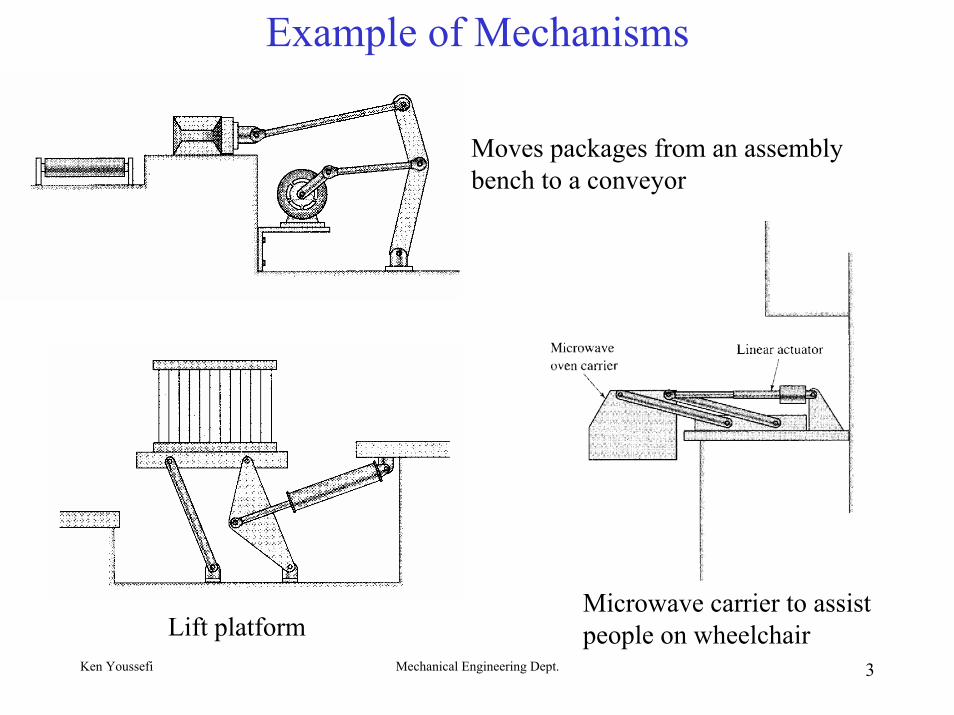
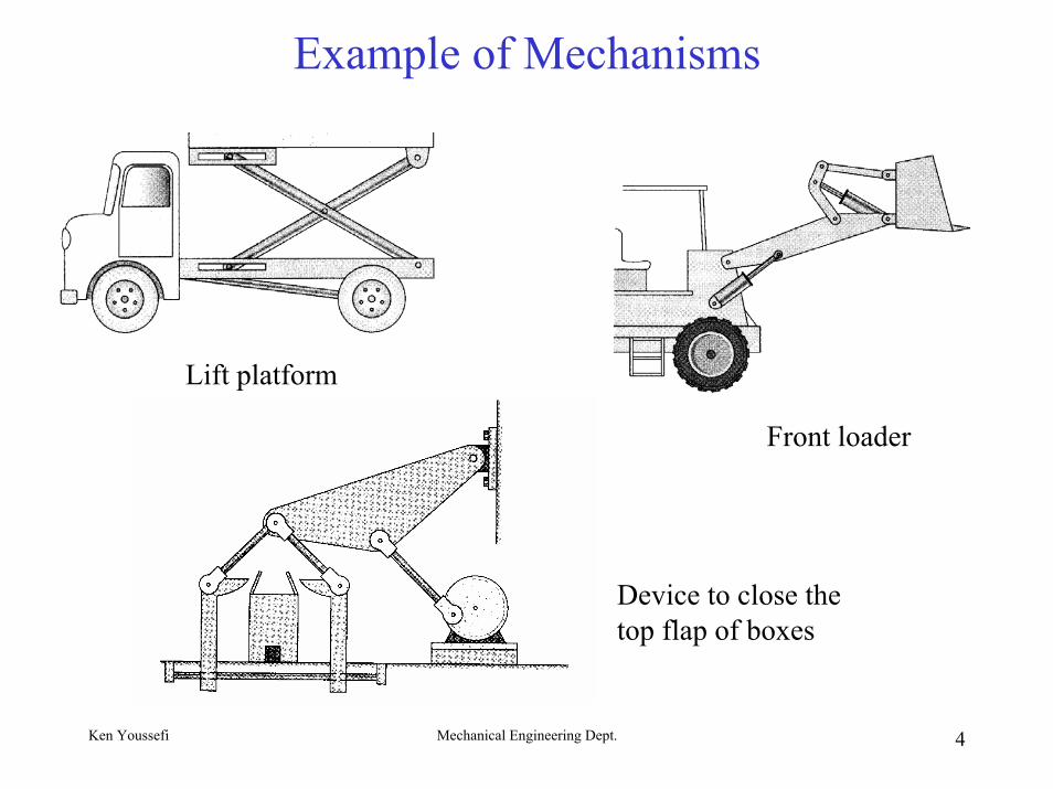
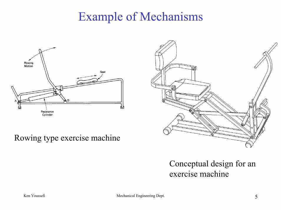
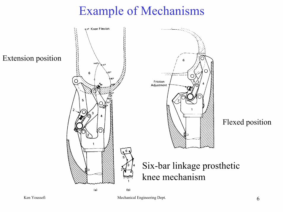
Example of Mechanisms
Moves packages from an assembly bench to a conveyor
Lift platformMicrowave carrier to assist people on wheelchair
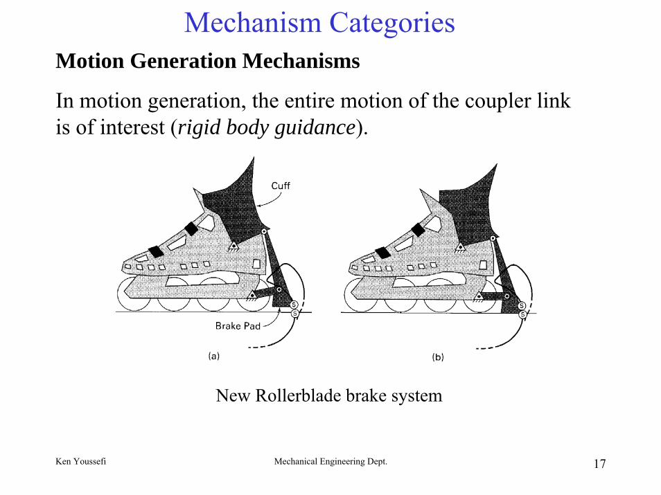
In motion generation, the entire motion of the coupler link is of interest (rigid body guidance).
New Rollerblade brake system
Ken Youssefi Mechanical Engineering Dept. 18
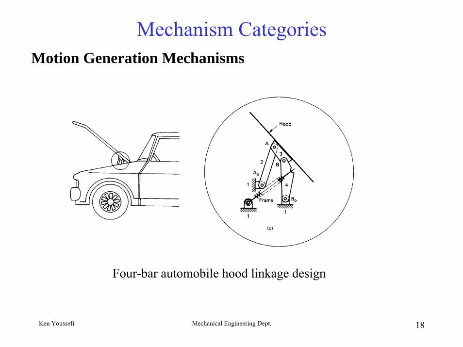
Mechanism CategoriesMotion Generation Mechanisms
Four-bar automobile hood linkage design
Ken Youssefi Mechanical Engineering Dept. 19
Mechanism Categories
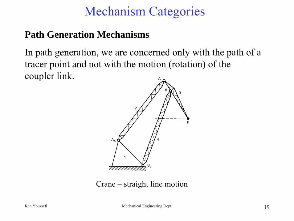
Path Generation Mechanisms
In path generation, we are concerned only with the path of a tracer point and not with the motion (rotation) of the coupler link.
Crane – straight line motion
Ken Youssefi Mechanical Engineering Dept. 20
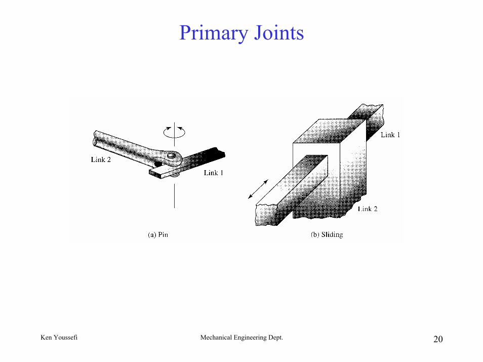
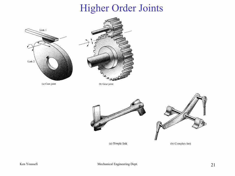
Primary Joints
Ken Youssefi Mechanical Engineering Dept. 21
Higher Order Joints
Ken Youssefi Mechanical Engineering Dept. 22
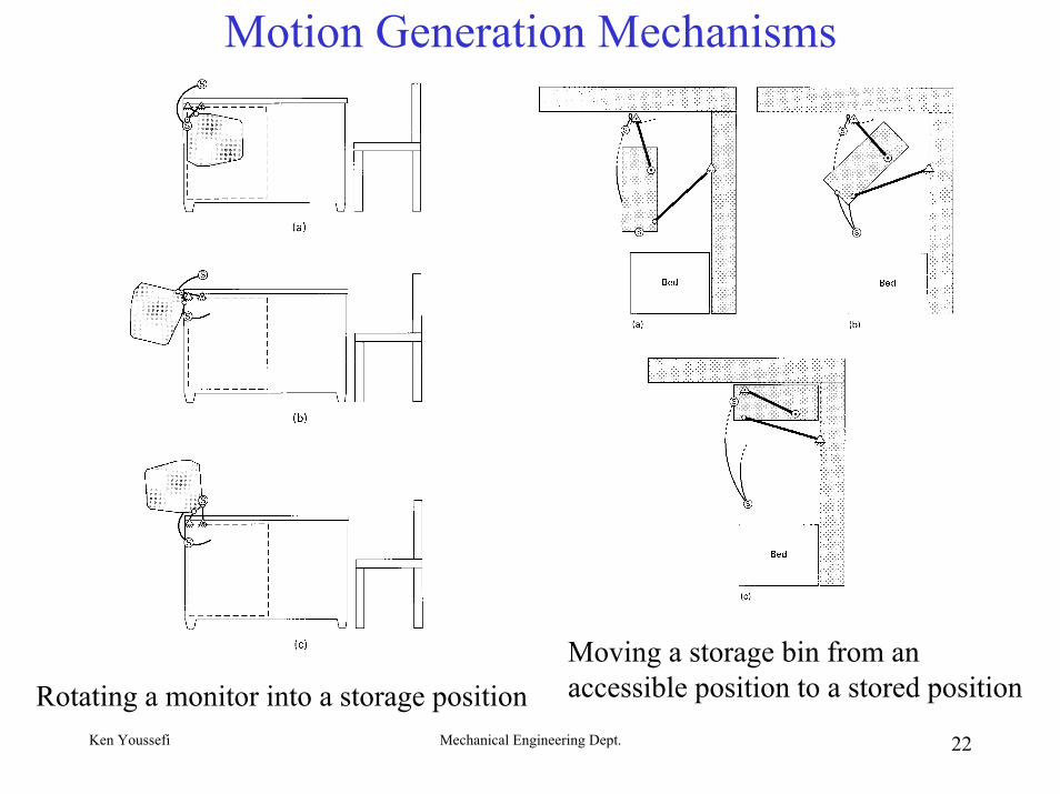
Motion Generation Mechanisms
Rotating a monitor into a storage positionMoving a storage bin from an accessible position to a stored position
Ken Youssefi Mechanical Engineering Dept. 23
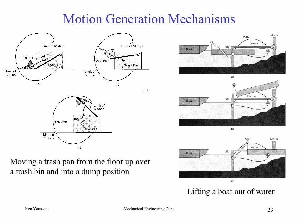
Motion Generation Mechanisms
Lifting a boat out of water
Moving a trash pan from the floor up over a trash bin and into a dump position
Ken Youssefi Mechanical Engineering Dept. 24
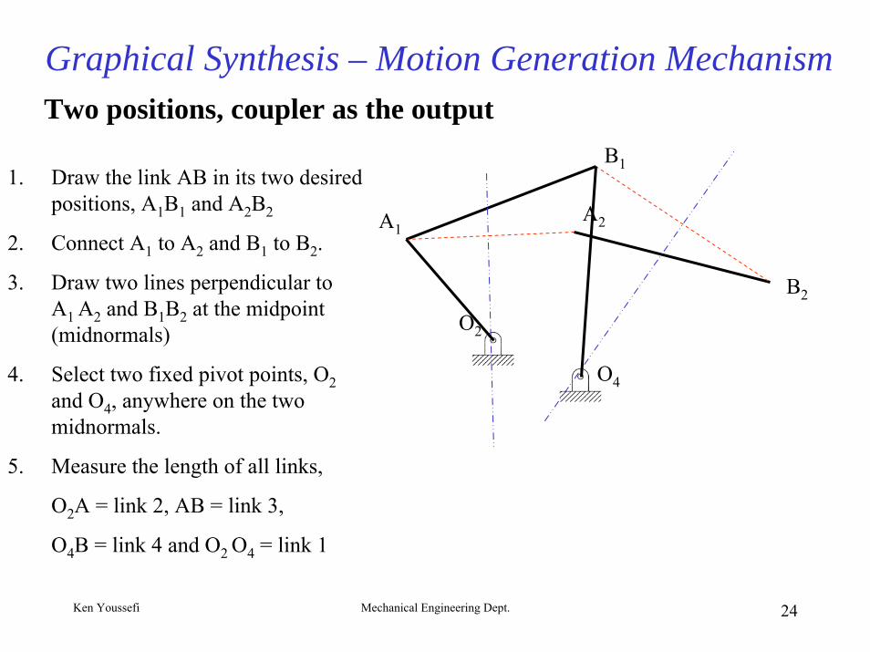
Graphical Synthesis – Motion Generation MechanismTwo positions, coupler as the output
A1A2
B1
O2
O4
1. Draw the link AB in its two desired positions, A1B1 and A2B2
2. Connect A1 to A2 and B1 to B2.
3. Draw two lines perpendicular to A1 A2 and B1B2 at the midpoint (midnormals)
4. Select two fixed pivot points, O2and O4, anywhere on the two midnormals.
5. Measure the length of all links,
O2A = link 2, AB = link 3,
O4B = link 4 and O2 O4 = link 1
B2
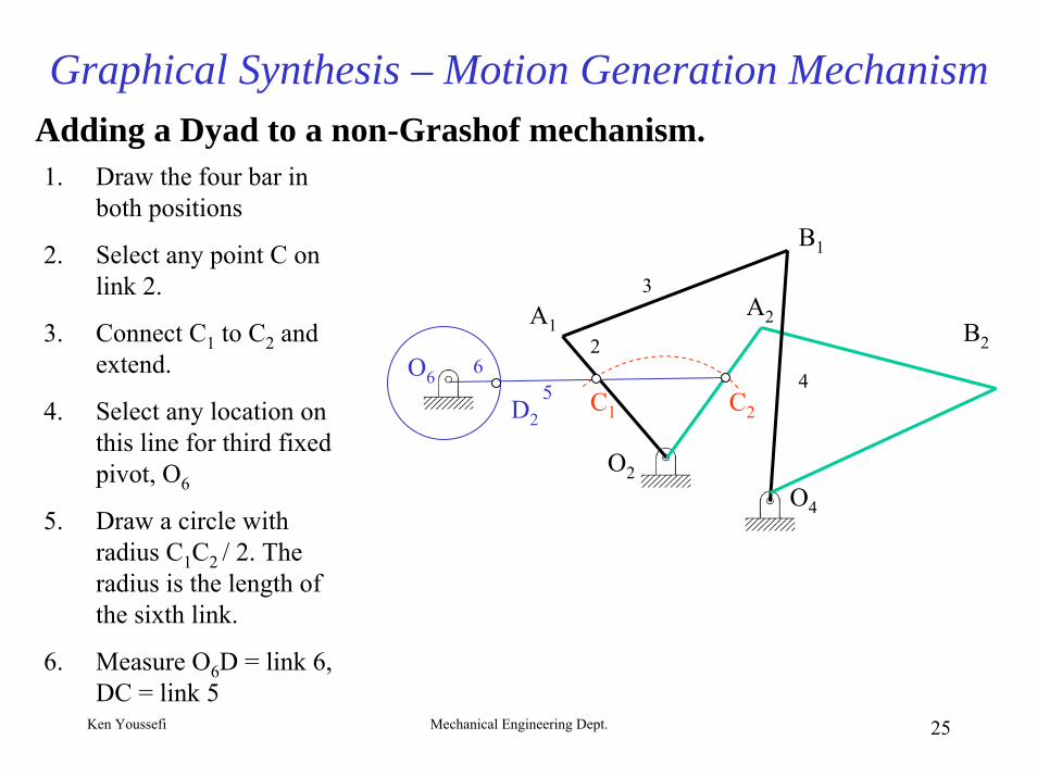
Graphical Synthesis – Motion Generation MechanismAdding a Dyad to a non-Grashof mechanism.1. Draw the four bar in
both positions
2. Select any point C on link 2.
3. Connect C1 to C2 and extend.
4. Select any location on this line for third fixed pivot, O6
5. Draw a circle with radius C1C2 / 2. The radius is the length of the sixth link.
6. Measure O6D = link 6, DC = link 5
O6
A1A2
B1
B2
O2O4
C1 C2D2
2
3
456
Ken Youssefi Mechanical Engineering Dept. 25
Ken Youssefi Mechanical Engineering Dept. 26
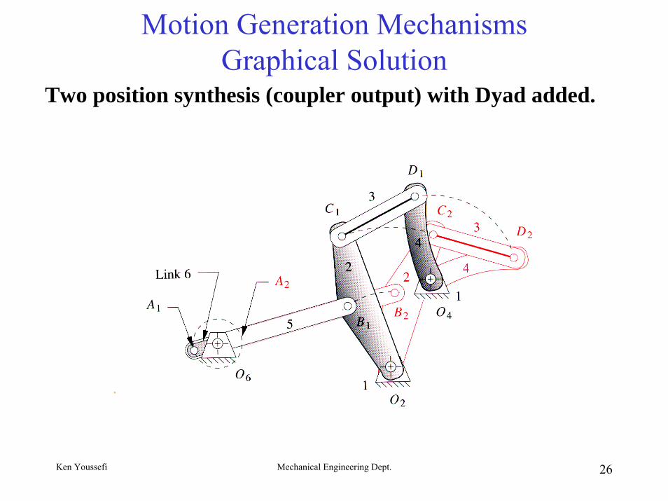
Motion Generation MechanismsGraphical Solution
Two position synthesis (coupler output) with Dyad added.
Ken Youssefi Mechanical Engineering Dept. 27
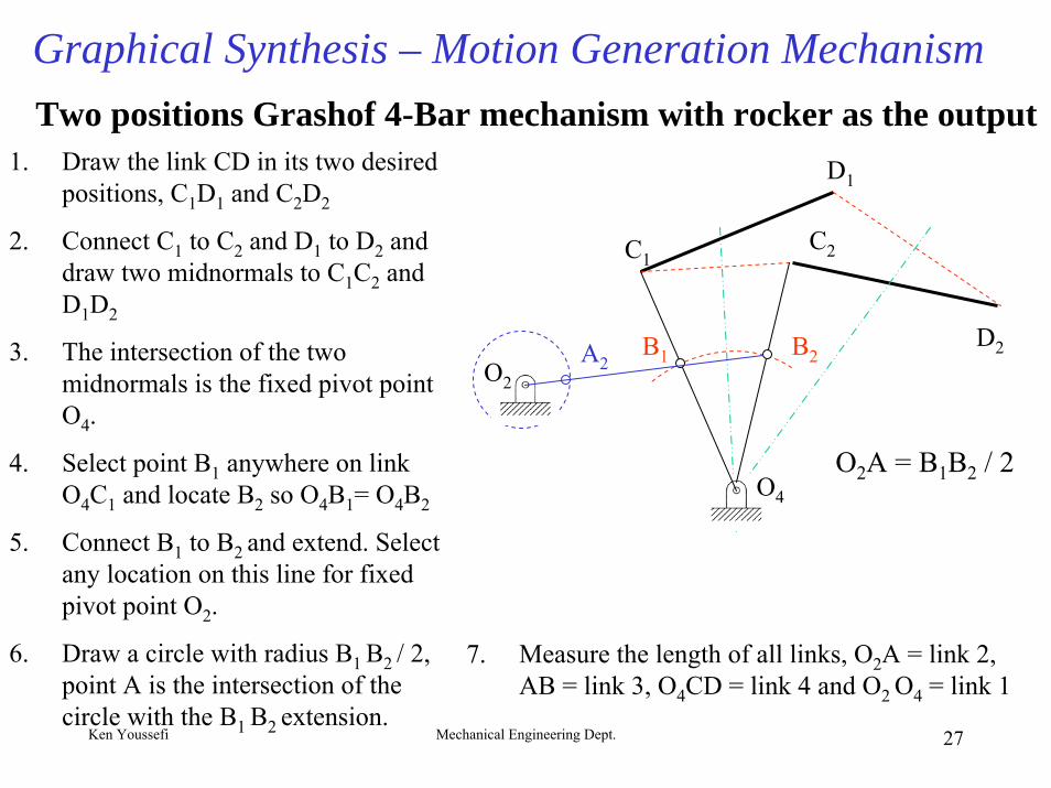
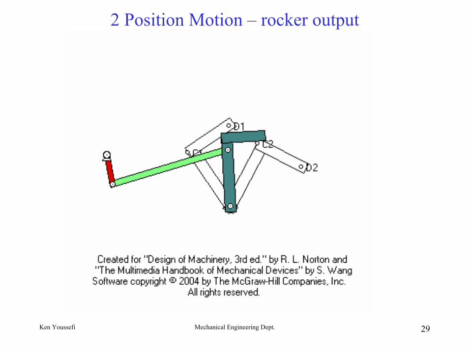
Graphical Synthesis – Motion Generation MechanismTwo positions Grashof 4-Bar mechanism with rocker as the output
1. Draw the link CD in its two desired positions, C1D1 and C2D2
2. Connect C1 to C2 and D1 to D2 and draw two midnormals to C1C2 and D1D2
3. The intersection of the two midnormals is the fixed pivot point O4.
4. Select point B1 anywhere on link O4C1 and locate B2 so O4B1= O4B2
5. Connect B1 to B2 and extend. Select any location on this line for fixed pivot point O2.
6. Draw a circle with radius B1 B2 / 2, point A is the intersection of the circle with the B1 B2 extension.
D1
C1C2
D2A2
O4
O2
O2A = B1B2 / 2
B1 B2
7. Measure the length of all links, O2A = link 2, AB = link 3, O4CD = link 4 and O2 O4 = link 1
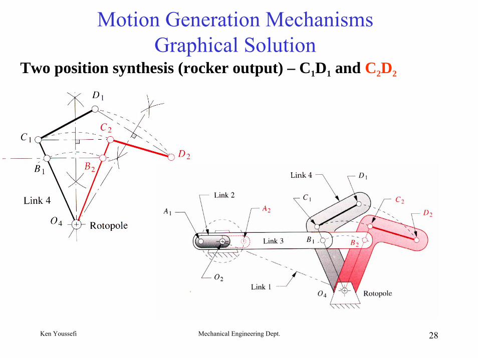
Motion Generation MechanismsGraphical Solution
Two position synthesis (rocker output) – C1D1 and C2D2
Ken Youssefi Mechanical Engineering Dept. 28
2 Position Motion – rocker output
Ken Youssefi Mechanical Engineering Dept. 29
Ken Youssefi Mechanical Engineering Dept. 30
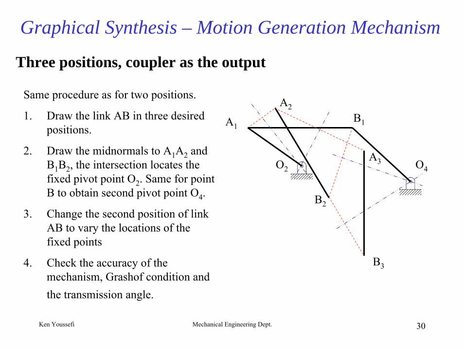
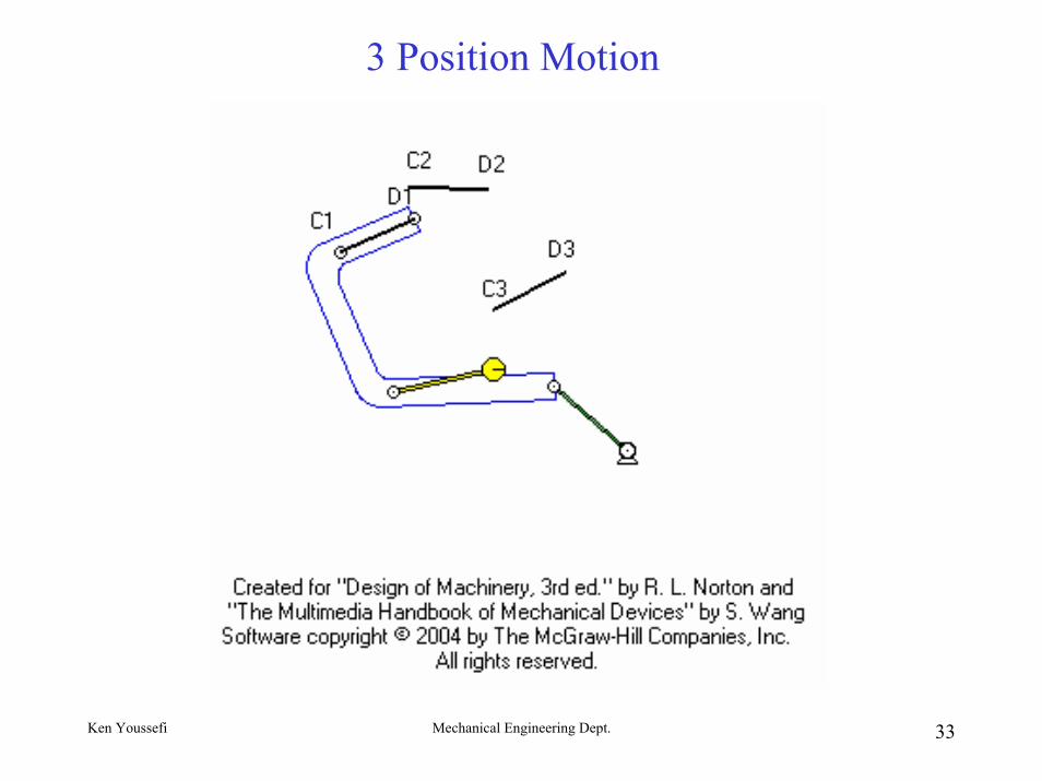
Graphical Synthesis – Motion Generation Mechanism
Three positions, coupler as the output
Same procedure as for two positions.
1. Draw the link AB in three desired positions.
2. Draw the midnormals to A1A2 and B1B2, the intersection locates the fixed pivot point O2. Same for point B to obtain second pivot point O4.
3. Change the second position of link AB to vary the locations of the fixed points
4. Check the accuracy of the mechanism, Grashof condition and the transmission angle.
O4O2
A2
A3
B1
B2
A1
B3
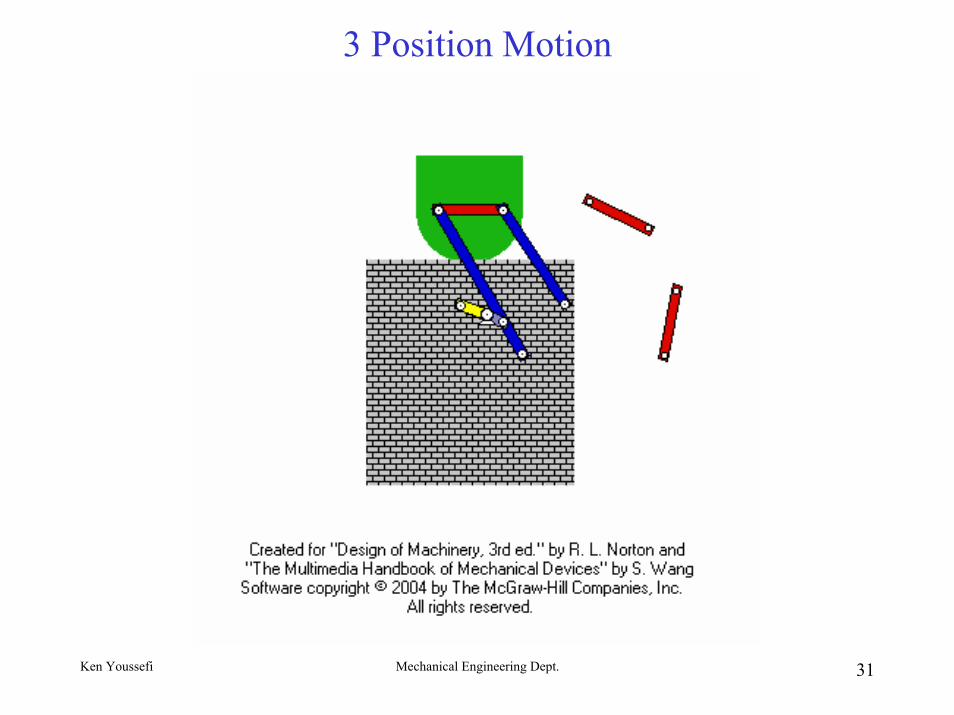
Ken Youssefi Mechanical Engineering Dept. 31
3 Position Motion
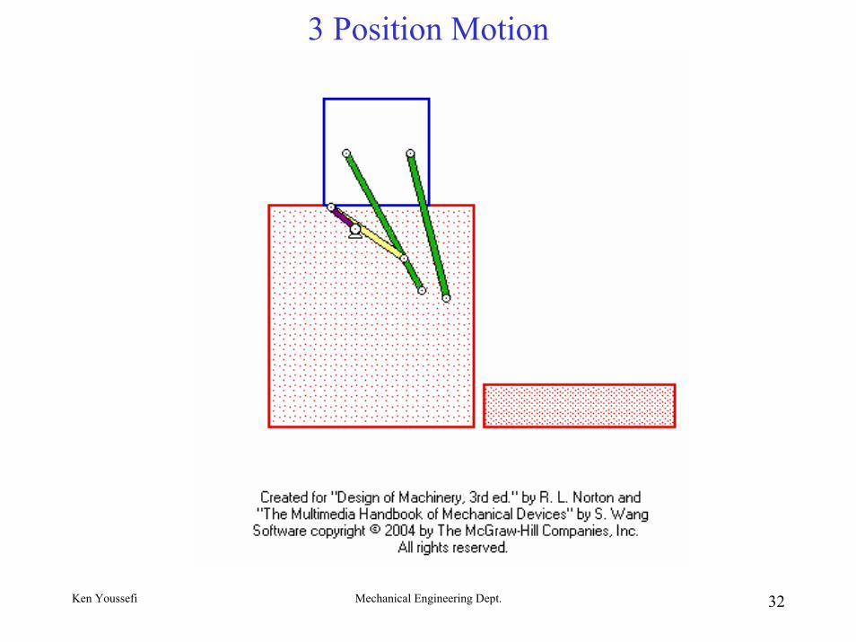
Ken Youssefi Mechanical Engineering Dept. 32
3 Position Motion
Ken Youssefi Mechanical Engineering Dept. 33
3 Position Motion
Ken Youssefi Mechanical Engineering Dept. 34
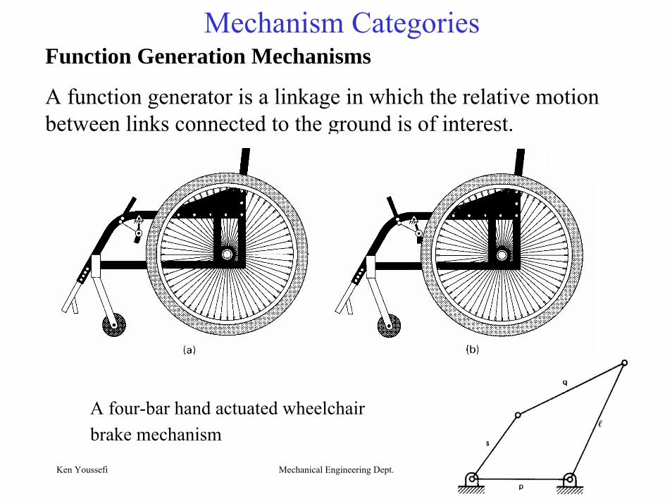
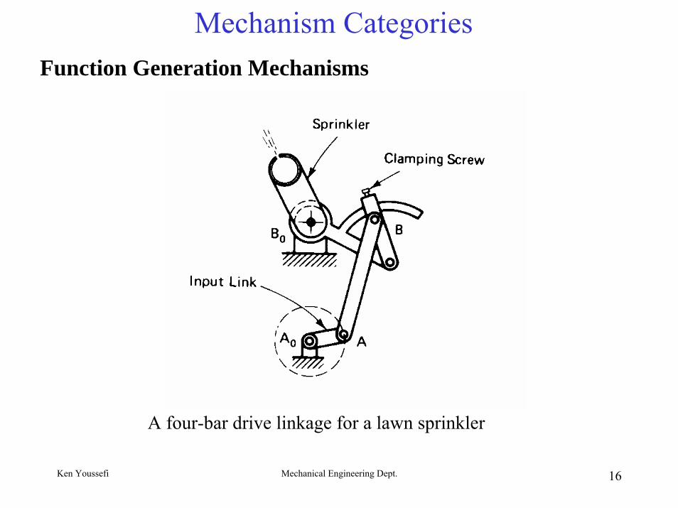
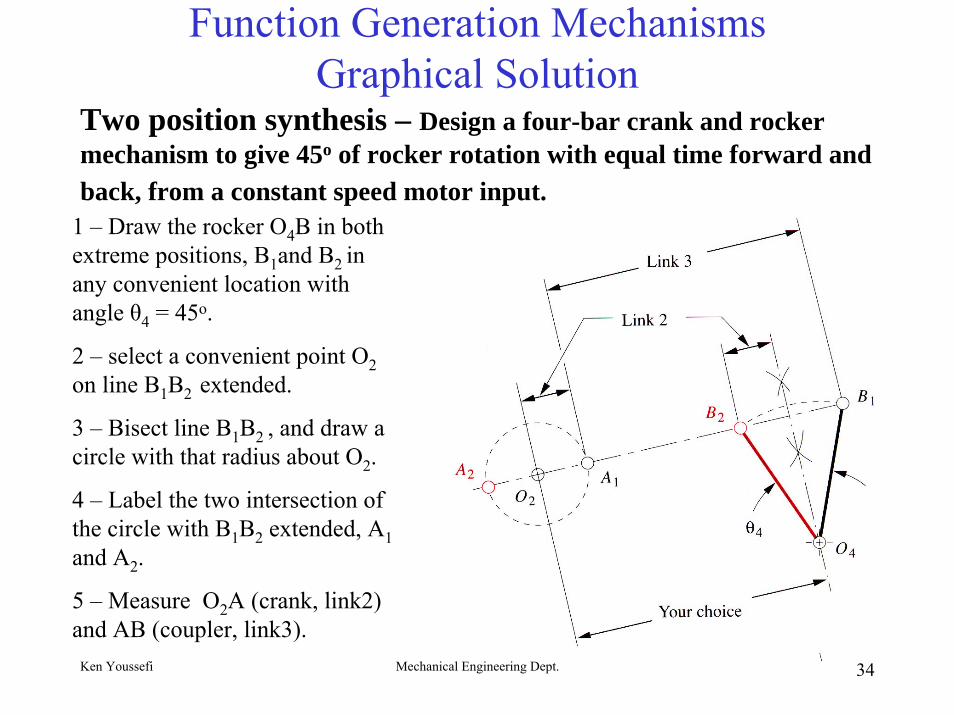
Function Generation MechanismsGraphical Solution
Two position synthesis – Design a four-bar crank and rocker mechanism to give 45o of rocker rotation with equal time forward and back, from a constant speed motor input.
1 – Draw the rocker O4B in both extreme positions, B1and B2 in any convenient location with angle θ4 = 45o.
2 – select a convenient point O2on line B1B2 extended.
3 – Bisect line B1B2 , and draw a circle with that radius about O2.
4 – Label the two intersection of the circle with B1B2 extended, A1and A2.
5 – Measure O2A (crank, link2) and AB (coupler, link3).
Ken Youssefi Mechanical Engineering Dept. 35
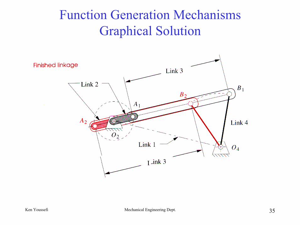
Function Generation MechanismsGraphical Solution
Ken Youssefi Mechanical Engineering Dept. 36
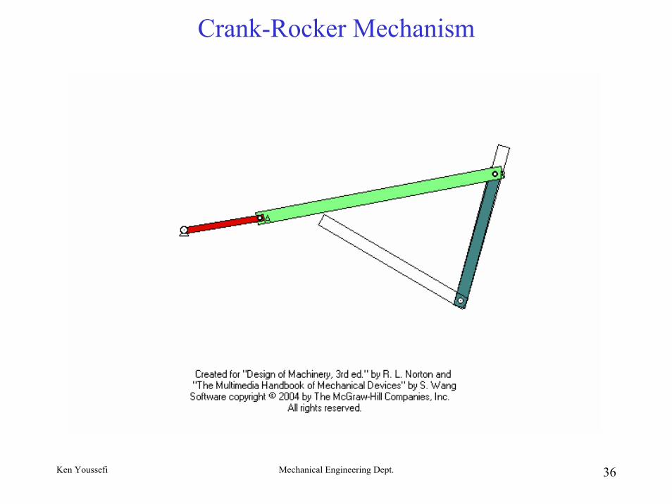
Crank-Rocker Mechanism
Ken Youssefi Mechanical Engineering Dept. 37
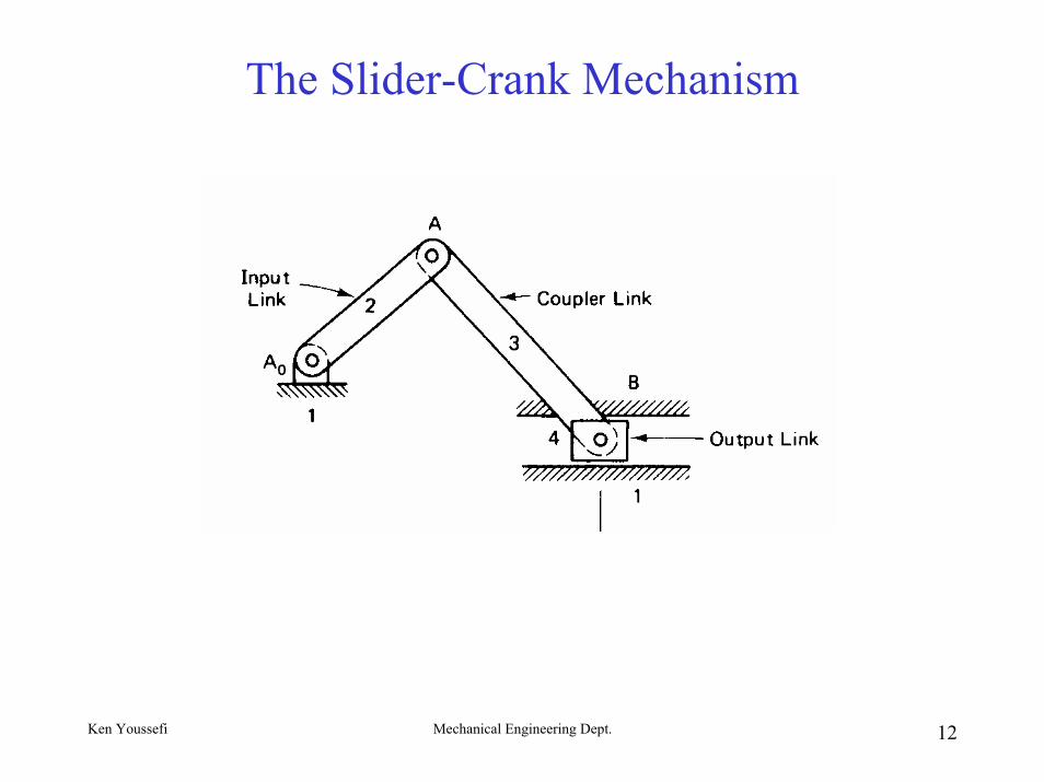
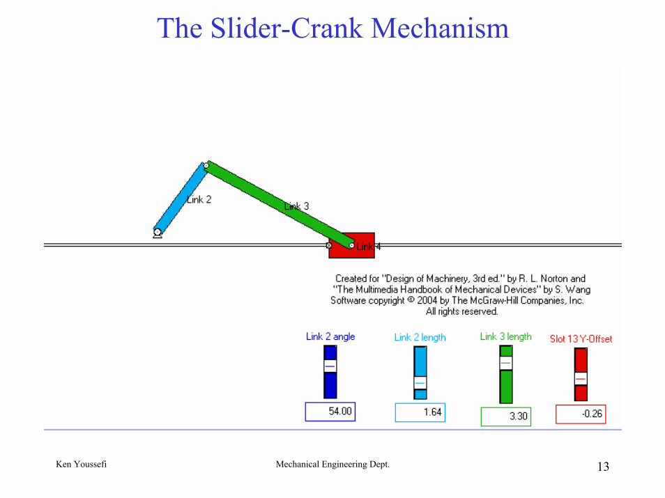
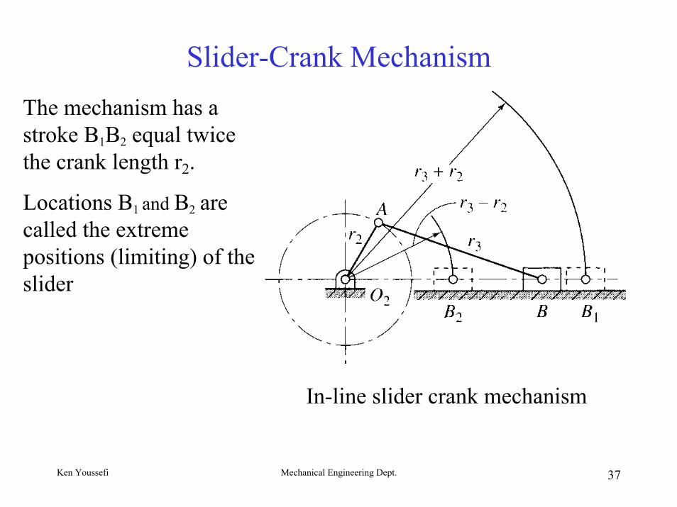
Slider-Crank MechanismThe mechanism has a stroke B1B2 equal twice the crank length r2.
Locations B1 and B2 are called the extreme positions (limiting) of the slider
In-line slider crank mechanism
Ken Youssefi Mechanical Engineering Dept. 38
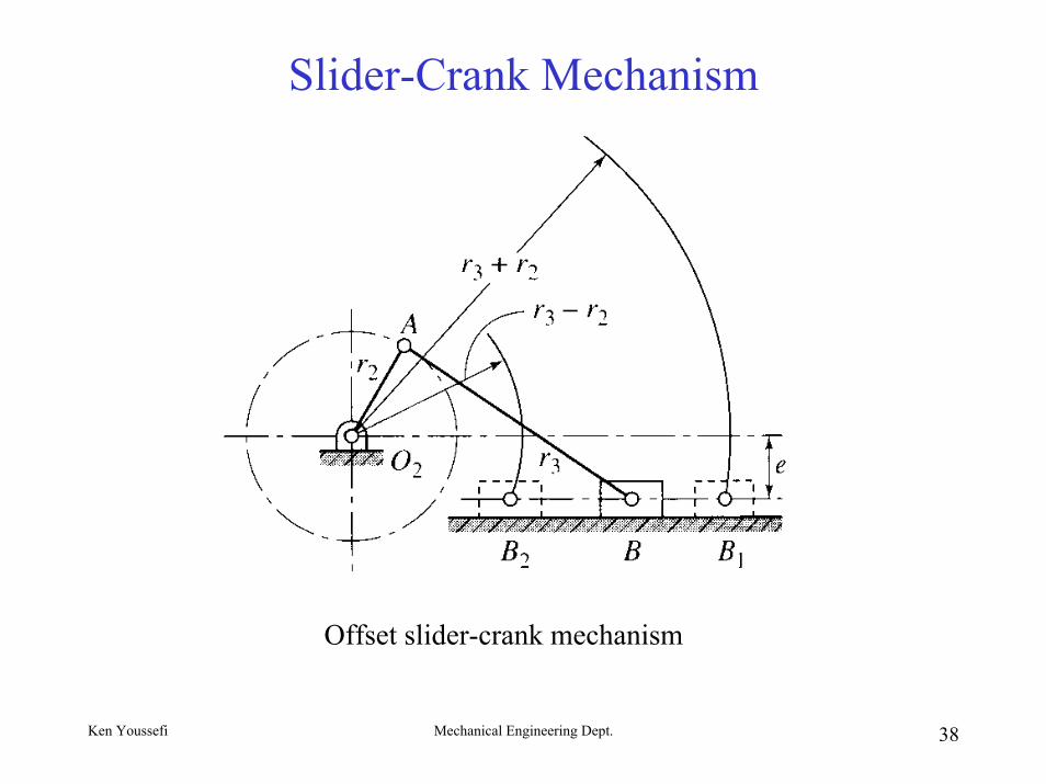
Slider-Crank Mechanism
Offset slider-crank mechanism
Ken Youssefi Mechanical Engineering Dept. 39
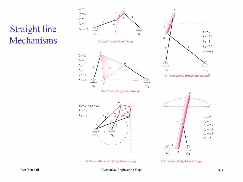
Straight line Mechanisms
Ken Youssefi Mechanical Engineering Dept. 40
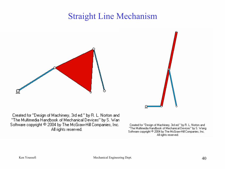
Straight Line Mechanism
Ken Youssefi Mechanical Engineering Dept. 41
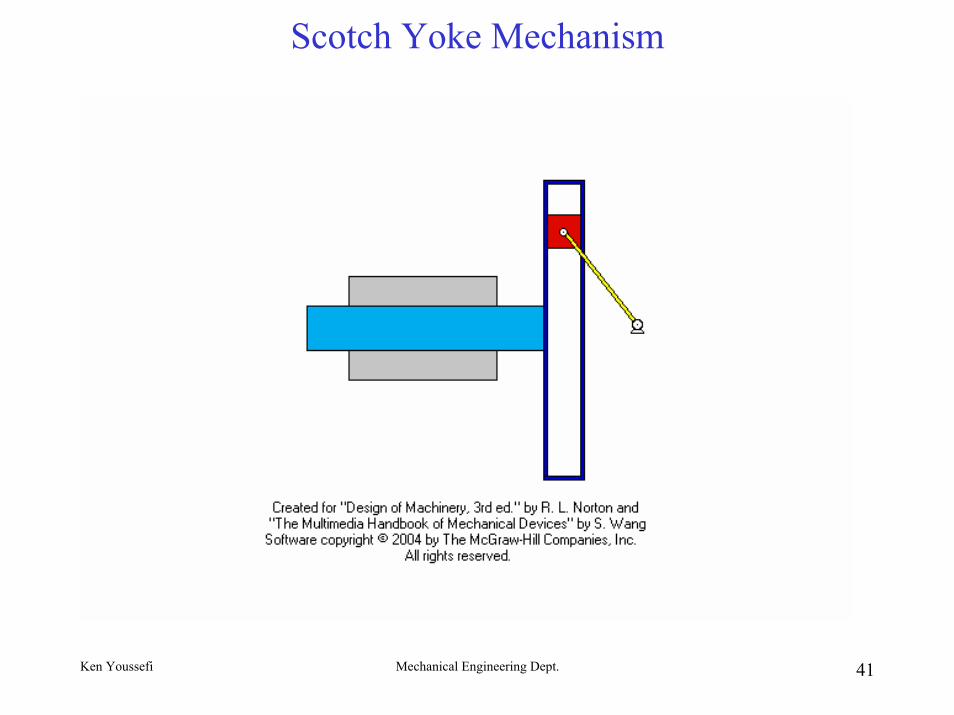
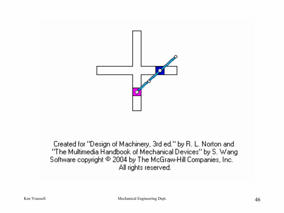
Scotch Yoke Mechanism
Ken Youssefi Mechanical Engineering Dept. 42
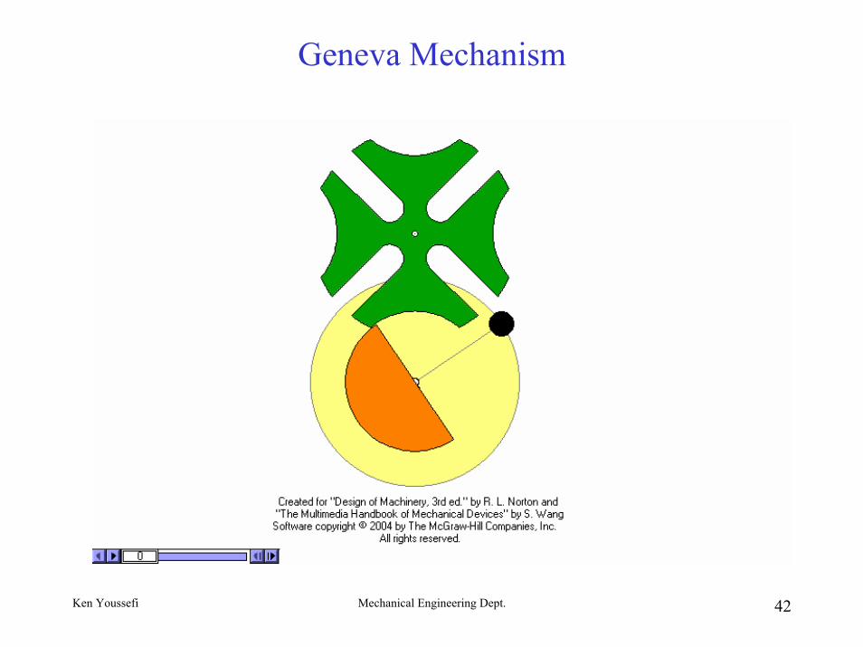
Geneva Mechanism
Ken Youssefi Mechanical Engineering Dept. 43
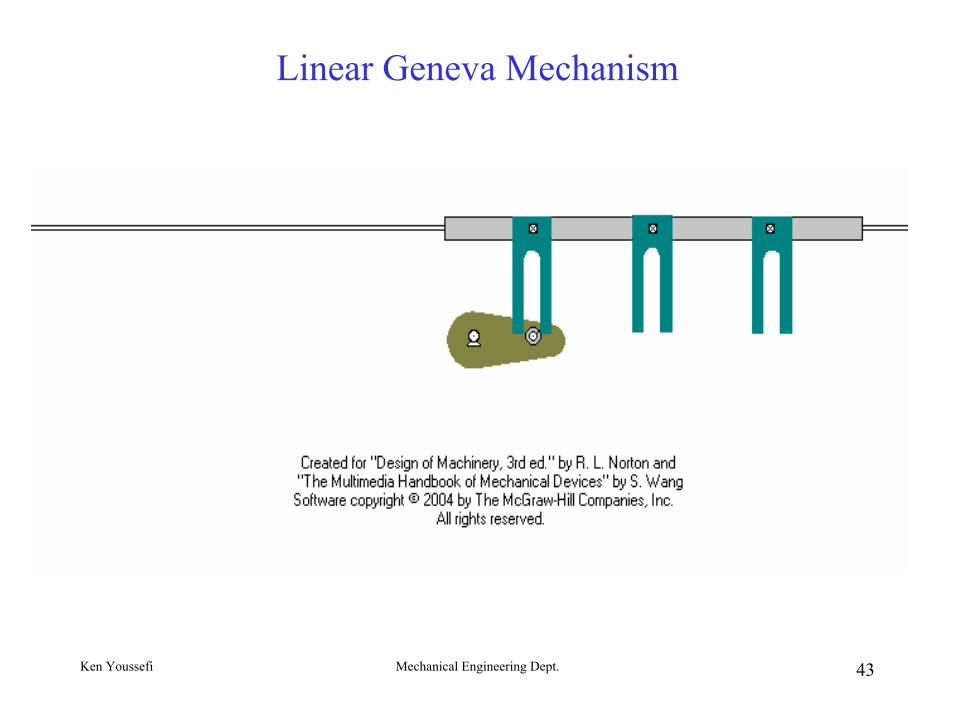
Linear Geneva Mechanism
Ken Youssefi Mechanical Engineering Dept. 44
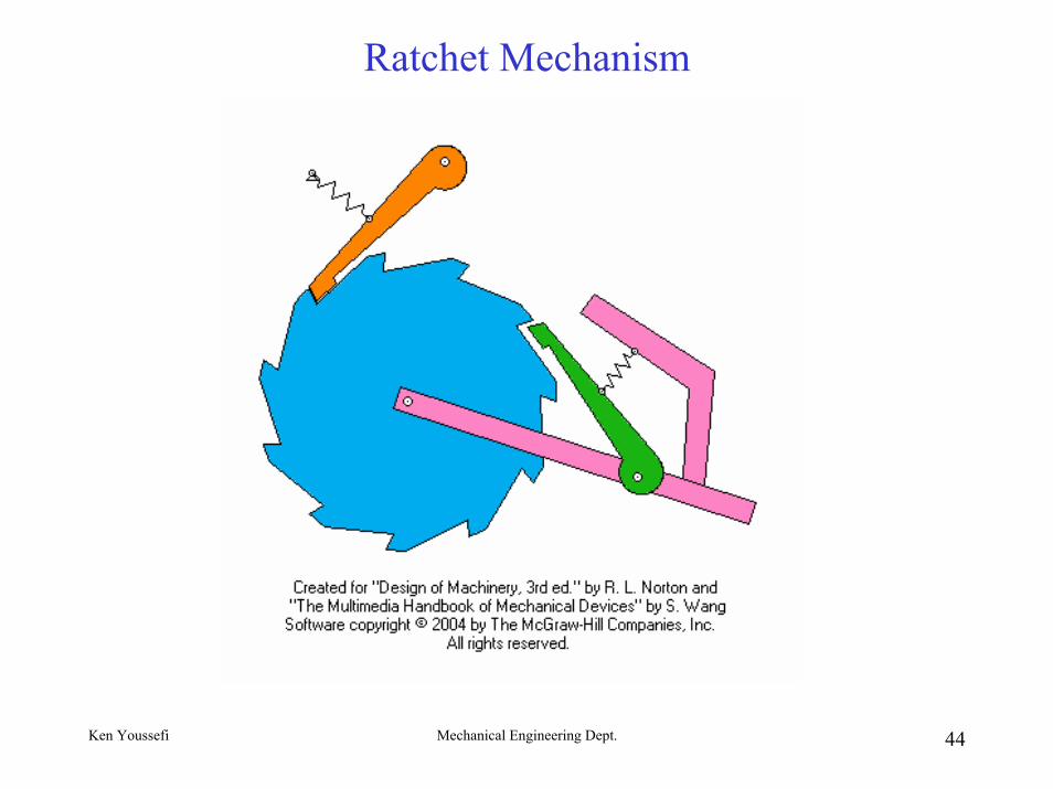
Ratchet Mechanism
Ken Youssefi Mechanical Engineering Dept. 45
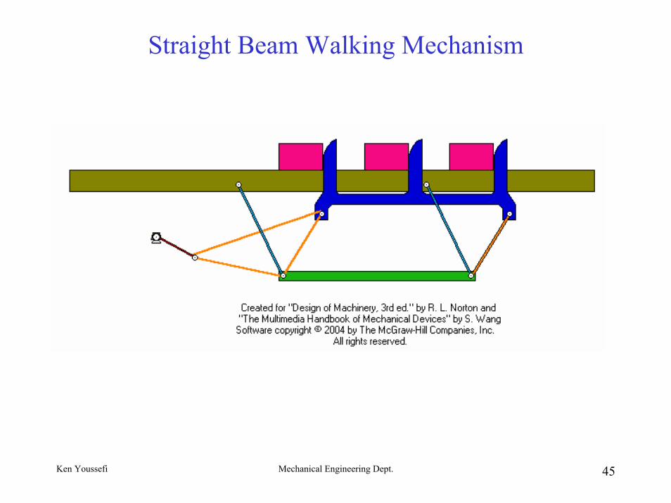
Straight Beam Walking Mechanism
Ken Youssefi Mechanical Engineering Dept. 46
Ken Youssefi Mechanical Engineering Dept. 47
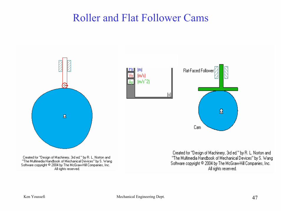
Roller and Flat Follower Cams
Ken Youssefi Mechanical Engineering Dept. 48
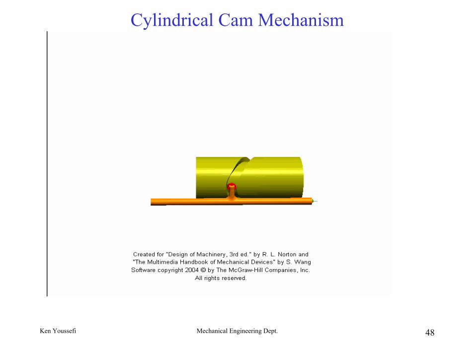
Cylindrical Cam Mechanism
Ken Youssefi Mechanical Engineering Dept. 49
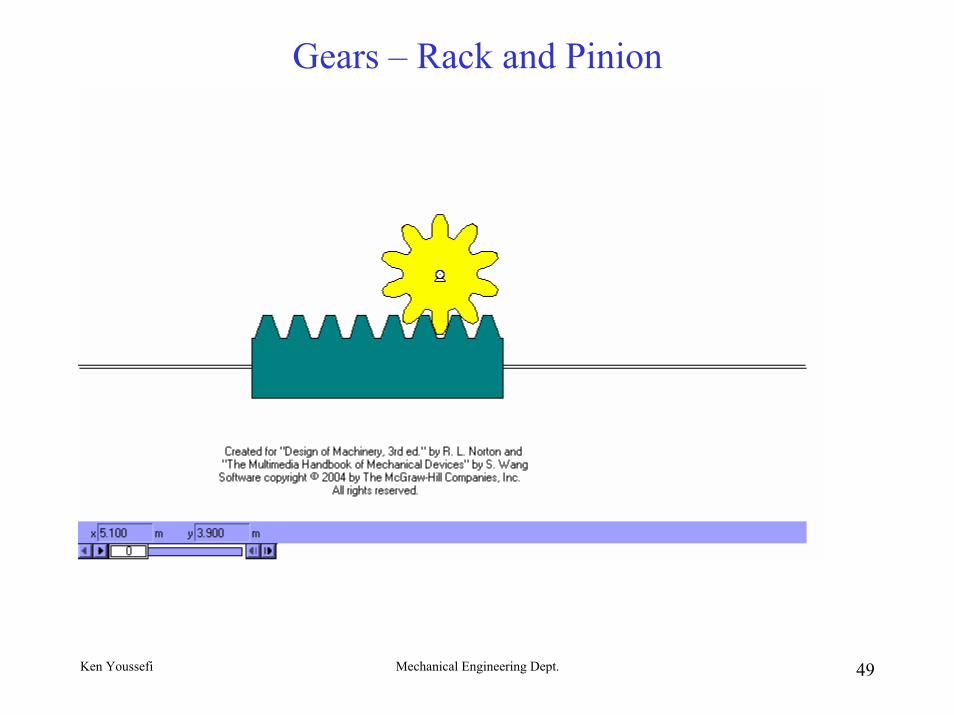
Gears – Rack and Pinion
Ken Youssefi Mechanical Engineering Dept. 50
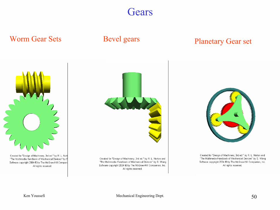
Gears
Worm Gear Sets Bevel gears Planetary Gear set
Ken Youssefi Mechanical Engineering Dept. 51
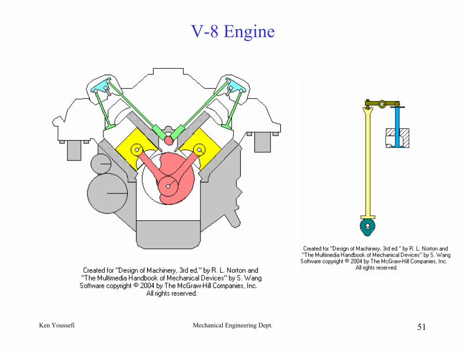
V-8 Engine
Ken Youssefi Mechanical Engineering Dept. 52
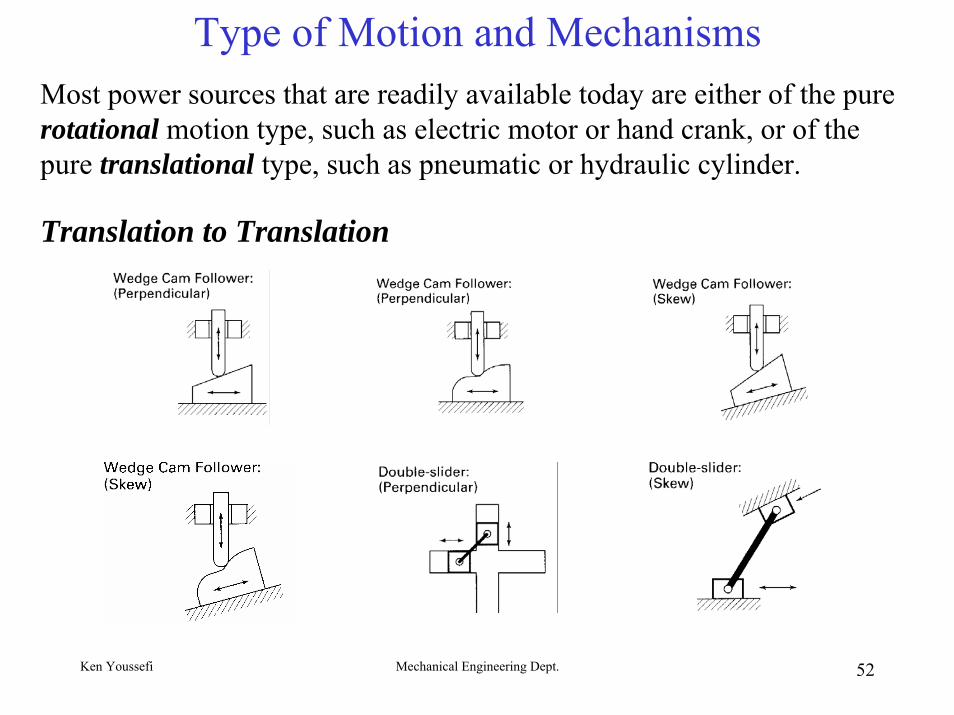
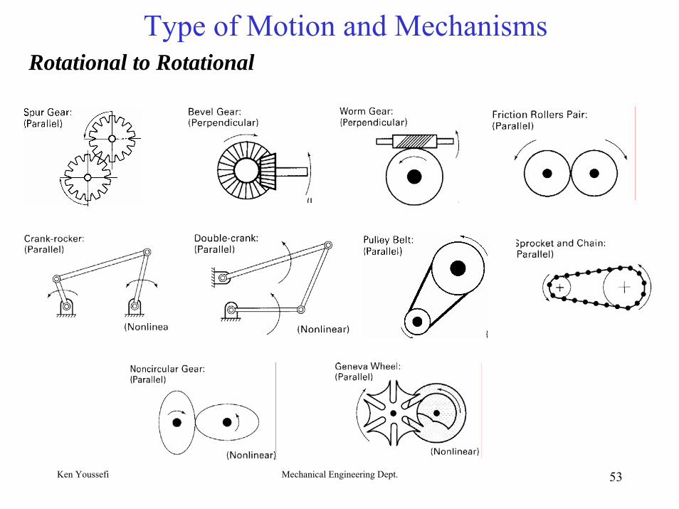
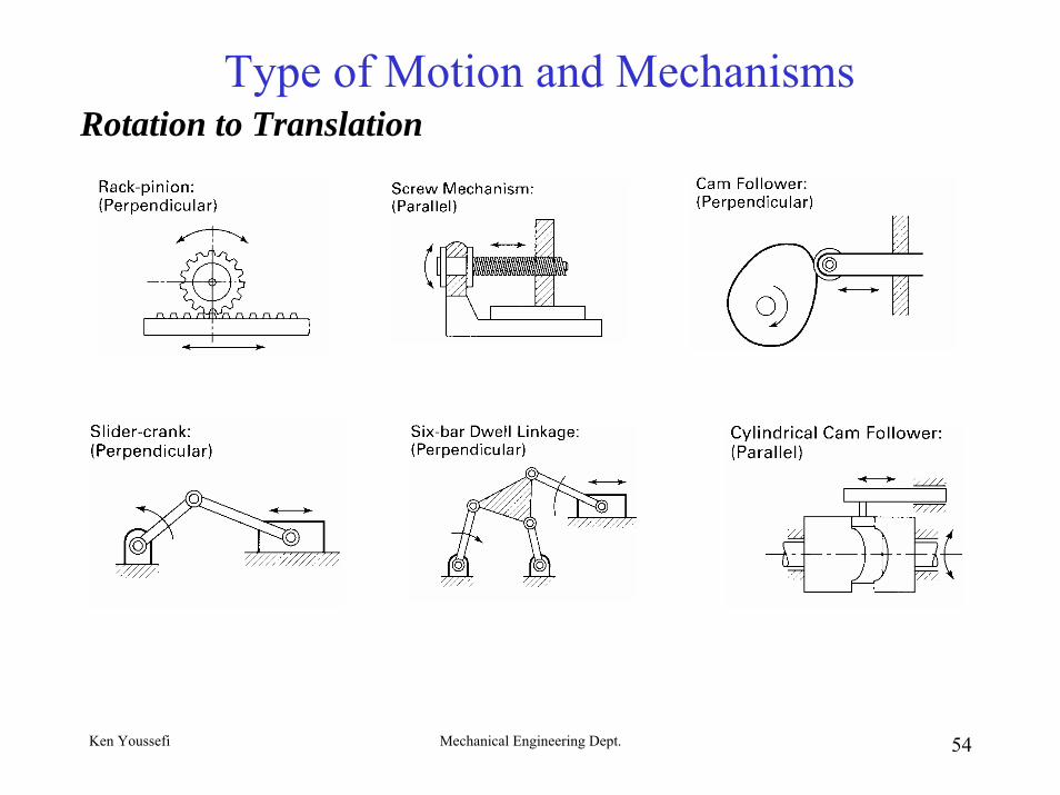
Type of Motion and MechanismsMost power sources that are readily available today are either of the pure rotational motion type, such as electric motor or hand crank, or of the pure translational type, such as pneumatic or hydraulic cylinder.
Translation to Translation
Ken Youssefi Mechanical Engineering Dept. 53
Type of Motion and MechanismsRotational to Rotational
Ken Youssefi Mechanical Engineering Dept. 54
Type of Motion and MechanismsRotation to Translation
Ken Youssefi Mechanical Engineering Dept. 55
References• Mechanism Design, Analysis and Synthesis by
Erdman and sander, fourth edition, Prentice-Hall, 2001,
• Machines and Mechanisms by Uicker, Pennock and Shigley, third edition, Oxford, 2002.
• Machines and Mechanisms by Myszka, Prentice-Hall, 1999