VARIATIONS IN RADIATION RESPONSE DUE TO HYDROGEN: MECHANISMS OF INTERFACE TRAP BUILDUP AND ANNEALING By David Russell Hughart Dissertation Submitted to the Faculty of the Graduate School of Vanderbilt University in partial fulfillment of the requirements for the degree of DOCTOR OF PHILOSOPHY in Electrical Engineering December, 2012 Nashville, Tennessee Approved: Professor Ronald D. Schrimpf Professor Daniel M. Fleetwood Professor Kenneth F. Galloway Professor Robert A. Reed Professor Sokrates T. Pantelides
Transcript
VARIATIONS IN RADIATION RESPONSE DUE TO HYDROGEN:
MECHANISMS OF INTERFACE TRAP BUILDUP AND ANNEALING
By
David Russell Hughart
Dissertation
Submitted to the Faculty of the
Graduate School of Vanderbilt University
in partial fulfillment of the requirements
for the degree of
DOCTOR OF PHILOSOPHY
in
Electrical Engineering
December, 2012
Nashville, Tennessee
Approved:
Professor Ronald D. Schrimpf
Professor Daniel M. Fleetwood
Professor Kenneth F. Galloway
Professor Robert A. Reed
Professor Sokrates T. Pantelides
ii
ACKNOWLEDGEMENTS
I would like to thank my advisor, Professor Ronald D. Schrimpf, for his guidance
and support. He has always been available to offer advice on many topics, from device
physics to presentation pointers. I am grateful for such personal attention and these
interactions have made all the years of research meetings enjoyable as well as
enlightening.
I would also like to thank Professor Daniel M. Fleetwood for his close
involvement in my research. He has taught me a great deal and constantly provided
helpful feedback and guidance on my papers and presentations. Both he and Professor
Schrimpf have devoted many hours to reviewing my work even when it is submitted late
at night, on a weekend, or both. I am very thankful for their patience and their
commitment to their students. Their extensive knowledge and passion for research
continue to inspire me.
Professor Blair R. Tuttle performed the density functional theory calculations that
supported these investigations and has spent many hours discussing and explaining the
physics involved, even remotely over video chat. I am very thankful to have had such a
great collaborator. I would like to Professor Sokrates T. Pantelides for his help in
understanding and interpreting the DFT calculations. I would also like to thank Professor
Kenneth F. Galloway and Professor Robert A. Reed for being on my committee.
The numerical simulations were performed using scripts written by Nicole L.
Rowsey. I am grateful to her for sharing her work and to Professor Mark E. Law for
giving me access to the Florida Object Oriented Device Simulator to perform the
simulations for this research.
iii
I would like to thank the U.S. Air Force HiREV program, the Air Force Office of
Scientific Research MURI program, the Defense Threat Reduction Agency, and the U.S.
Navy for their support of this research.
I am extremely grateful to my friends in the Radiation Effects and Reliability
group. They have supported me as both colleagues and friends. Sarah, Jon, and Vishwa
have always been the voices of experience and calm and I am indebted to them for their
counsel whenever I felt overwhelmed. I have been very lucky to have Nick as a friend,
especially one that can stand living with me for four years. Stephanie, Ashley, Cher,
Nadia, and Farah have kept me sane when preparing for countless research meetings. I
have always been able to count on Sandeepan and Tania for in-depth discussions, both
technical and personal, and I thank them for always keeping my spirits high. I would also
like to thank Nick, Mike, Nelson, Ray, Daniel, Matt, Pierre, Beth, Michele, Sri, Enxia,
Geoff, Nathaniel, Karen, and Paula. It has been a pleasure to spend my graduate school
years with such people.
Finally, I would like to thank my parents, for always encouraging and supporting
me in whatever I do. They have put up with my busy schedule (resulting in many missed
holidays) and my frustrations and disappointments. In response they have always
reminded me of how much they care through many phone calls and cards. Thank you for
your unconditional love at all times.
iv
TABLE OF CONTENTS
Page
ACKNOWLEDGEMENTS ................................................................................................ ii
LIST OF FIGURES ........................................................................................................... vi
Chapter
I. INTRODUCTION ...................................................................................................1
II. INTERFACE TRAP FORMATION .......................................................................5
Interface Trap Creation ................................................................................5 ELDRS .........................................................................................................7 Excess Base Current in Bipolar Transistors ...............................................10 E’ Centers ...................................................................................................12 Hydrogen Enhanced Degradation ..............................................................12 Modeling H2 Interactions ...........................................................................15 Density Functional Theory Calculations ...................................................17 Elevated Temperature Irradiation (ETI) ....................................................18
III. HYDROGEN INTERACTIONS WITH COMMON OXIDE DEFECTS ............20
Oxygen Vacancy Formation ......................................................................20 Hydrogen Reactions at Vo Defects ............................................................21 Proton Generation at High and Low Levels of Molecular Hydrogen ........26
IV. PROTON LOSS AT ELEVATED TEMPERATURES – ANALYTICAL
MODEL .................................................................................................................31
Experimental Observations ........................................................................31 Proton Generation and Trapping ................................................................33 Reaction Rates ...........................................................................................34 Competing Reactions at Elevated Temperatures .......................................38
V. INTERFACE TRAP BUILDUP AND ANNEALING AT ELEVATED
v
TEMPERATURES– NUMERICAL MODEL ......................................................43
Model Details .............................................................................................44 Varying H2 Concentration ..........................................................................47 Comparison to Experimental Data .............................................................48 Contributions of Proton Loss Reactions ....................................................49 Variations in Defect Concentration ...........................................................51 Varying H2 Concentration and Temperature .............................................53 Elevated Temperature Irradiation Testing .................................................56 Schematic Illustration ................................................................................61
V. SUMMARY AND CONCLUSIONS ....................................................................64
2.1 Schematic diagram of charge carrier generation, transport and interactions within SiO2. After [15]. .......................................................................................................7
2.2 Relative damage (enhancement factor) versus dose rate for several different
bipolar ICs [7]. .........................................................................................................8 2.3 Interface-trap concentration versus dose rate for lateral pnp bipolar transistors
irradiated to 30 krad(Si) in three different concentrations of molecular hydrogen [19]. ........................................................................................................................10
2.4 Sc Cross section of a lateral pnp bipolar transistor showing the radiation-induced
interface traps acting as recombination centers at the surface of the transistor where the current is flowing when biased in forward active mode. After [23]. ....11
2.5 Plot of output current versus dose for AD590 transducers in packages containing
small concentrations of hydrogen and packages with no detectable level of hydrogen [3]. ..........................................................................................................14
2.6 Radiation-induced interface traps and oxide trapped charge versus molecular
hydrogen concentration in the field oxide for GLPNP transistors irradiated to 30 krad(SiO2) [4]. ........................................................................................................15
3.1 Relative formation energy of oxygen vacancies versus Si-Si bond length [11]. ...21 3.2 Reaction energies for the dissociation of H2 at a positively charged oxygen
vacancy in the dimer configuration [11]. Points A, B, C, and D are referred to in the text. ...................................................................................................................23
3.3 Reaction energies for the dissociation of H2 at a positively charged oxygen
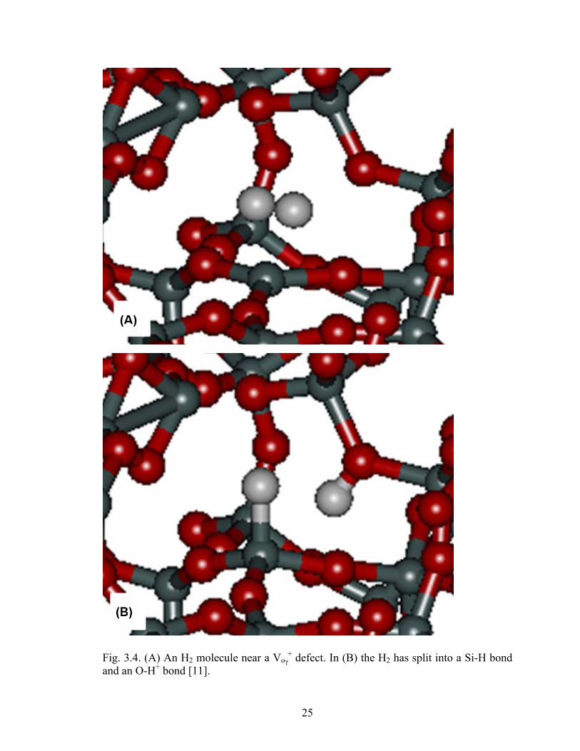
vacancy in the puckered configuration [11]. ..........................................................24 3.4 (A) An H2 molecule near a Voγ
+ defect. In (B) the H2 has split into a Si-H bond and an O-H+ bond [11]. ..........................................................................................25
3.5 Reaction energies for the dissociation of H2 at a neutral oxygen vacancy to create
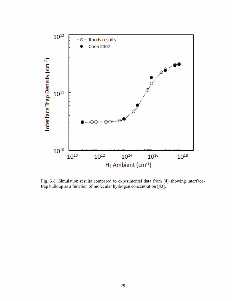
a doubly hydrogenated vacancy [11]. ....................................................................27 3.6 Simulation results compared to experimental data from [4] showing interface-trap
buildup as a function of molecular hydrogen concentration [43]. .........................29
vii
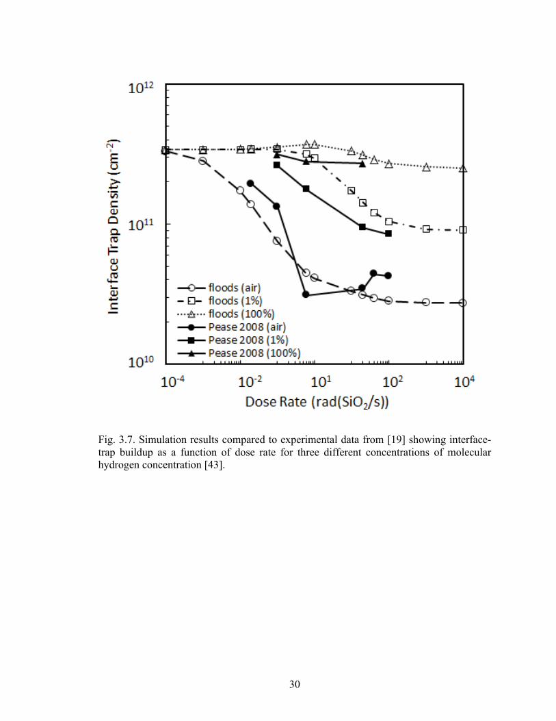
3.7 Simulation results compared to experimental data from [19] showing interface-
trap buildup as a function of dose rate for three different concentrations of molecular hydrogen concentration [43]. ................................................................30
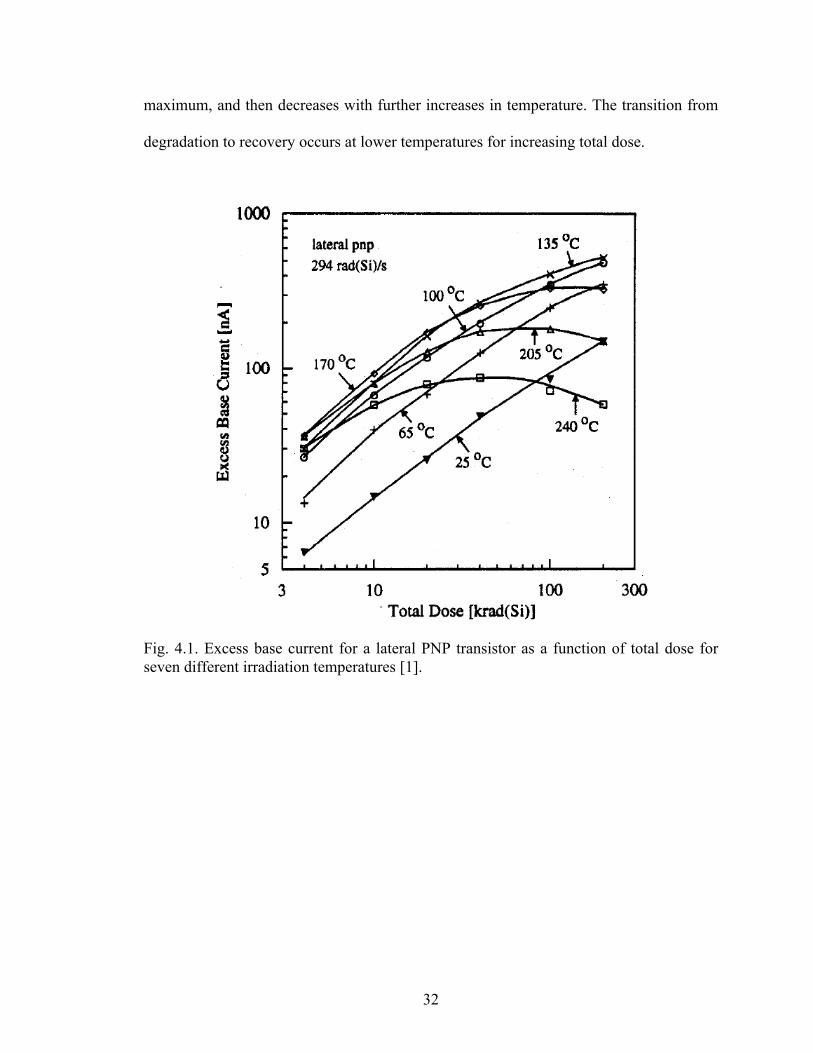
4.1 Excess base current for a lateral PNP transistor as a function of total dose for
seven different irradiation temperatures [1]. ..........................................................32 4.2 Excess base current for a lateral PNP transistor as a function of irradiation
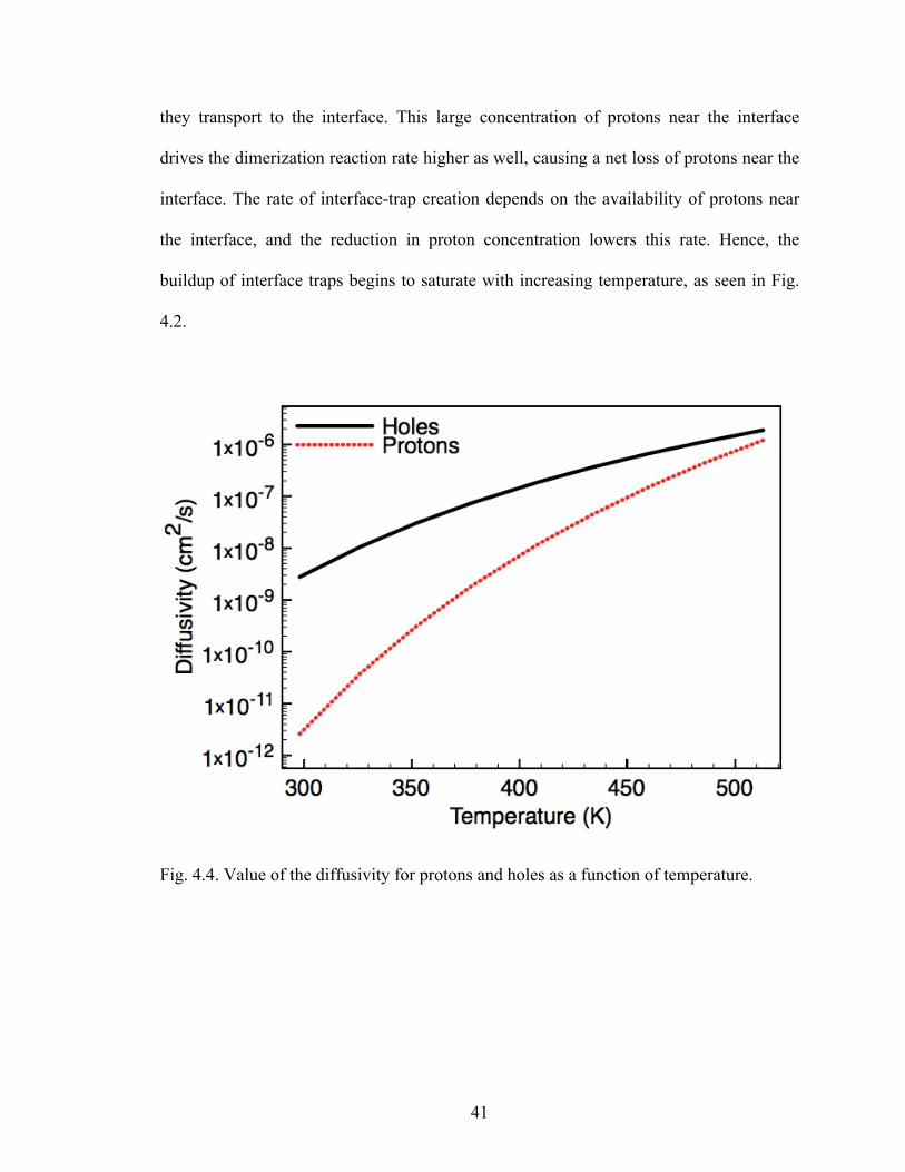
temperature for six different total doses [1]. ..........................................................33 4.3 View of the oxide showing the relative concentrations of protons and VH defects
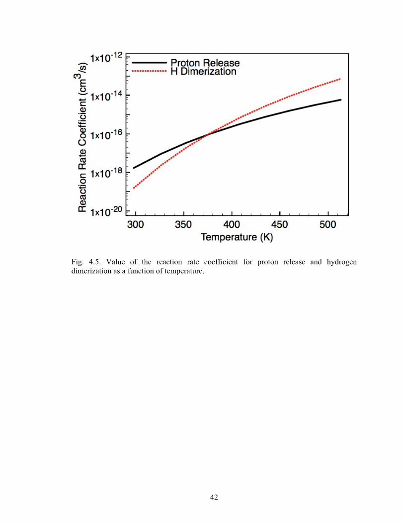
in the oxide. ............................................................................................................37 4.4 Value of the diffusivity for protons and holes as a function of temperature. ........41 4.5 Value of the reaction rate coefficient for proton release and hydrogen
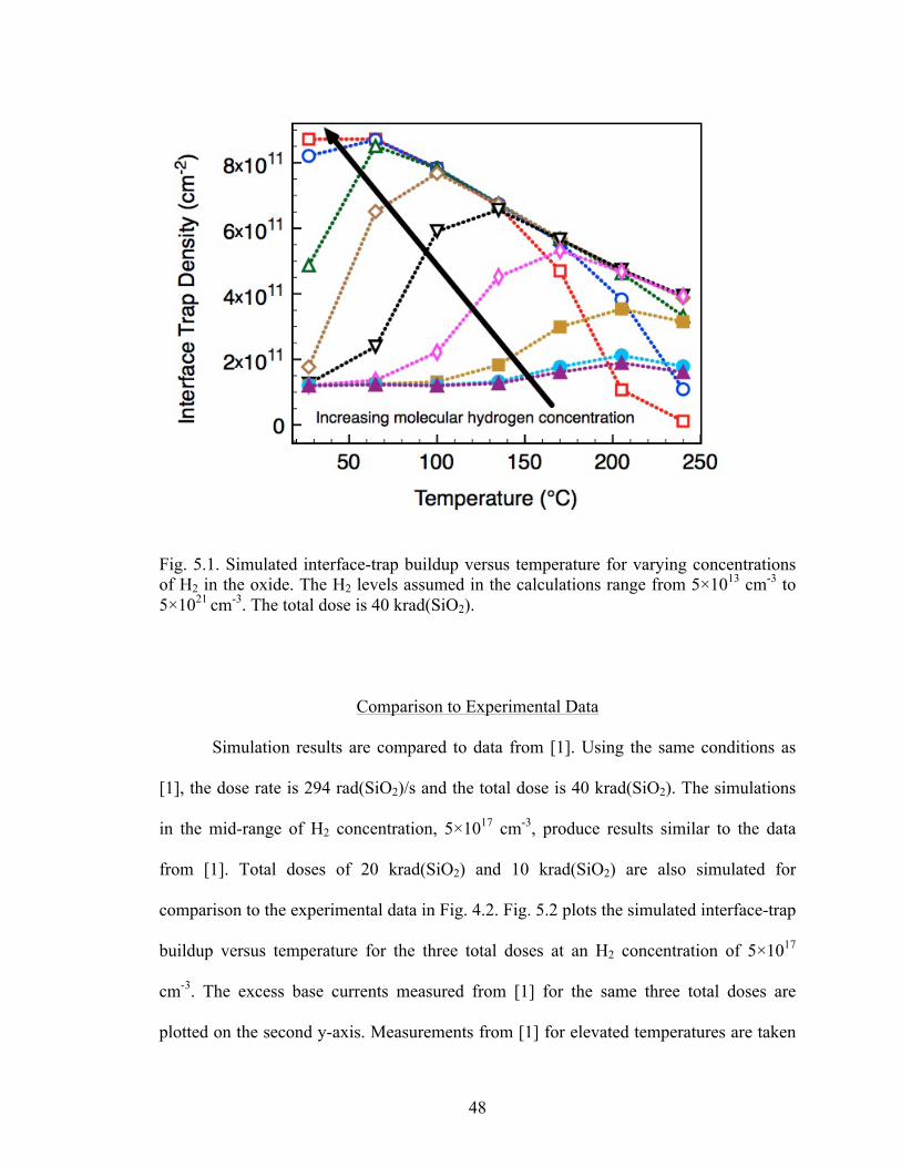
dimerization as a function of temperature. ............................................................42 5.1 Simulated interface-trap buildup versus temperature for varying concentrations of
H2 in the oxide. The H2 levels assumed in the calculations range from 5×1013 cm-3 to 5×1021 cm-3. The total dose is 40 krad(SiO2). ....................................................48
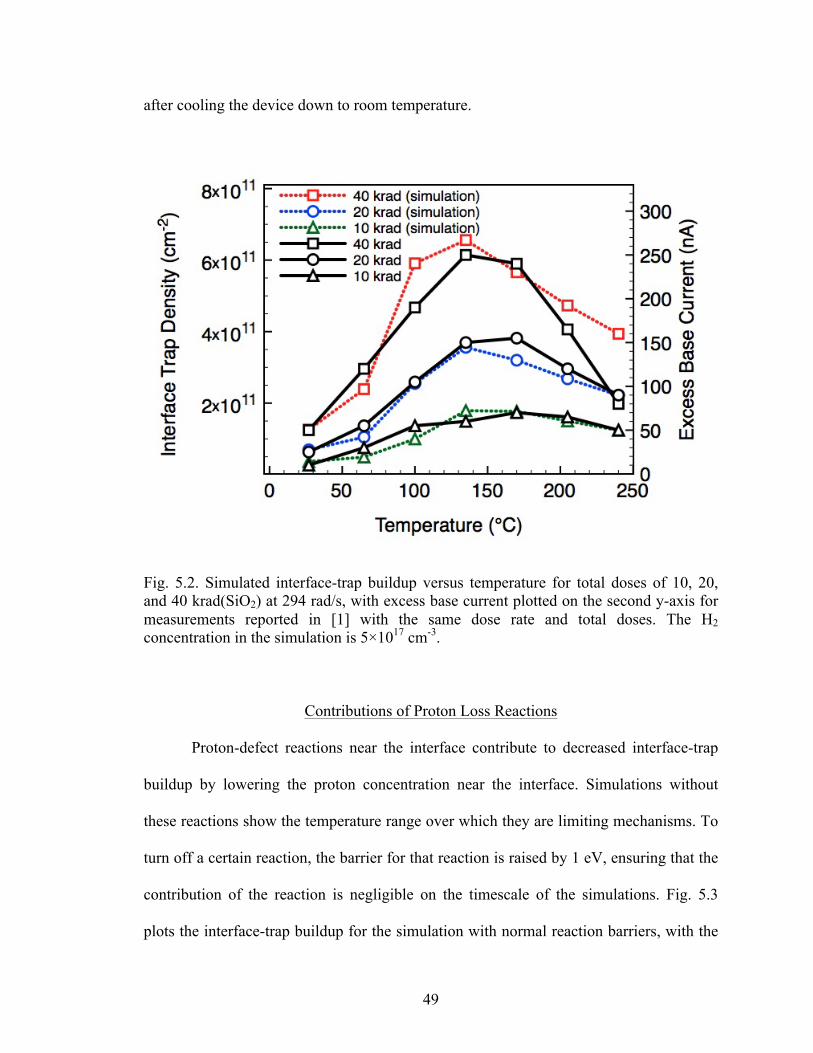
5.2 Simulated interface-trap buildup versus temperature for total doses of 10, 20, and
40 krad(SiO2) at 294 rad/s, with excess base current plotted on the second y-axis for measurements reported in [1] with the same dose rate and total doses. The H2 concentration in the simulation is 5×1017 cm-3. .....................................................49
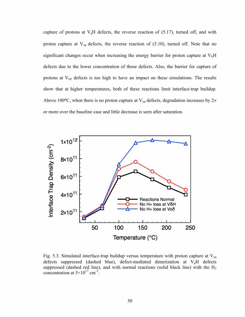
5.3 Simulated interface-trap buildup versus temperature with proton capture at Voδ
defects suppressed (dashed blue), defect-mediated dimerization at VδH defects suppressed (dashed red line), and with normal reactions (solid black line) with the H2 concentration at 5×1017 cm-3. ............................................................................50
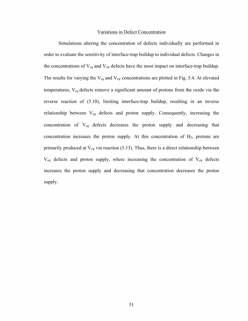
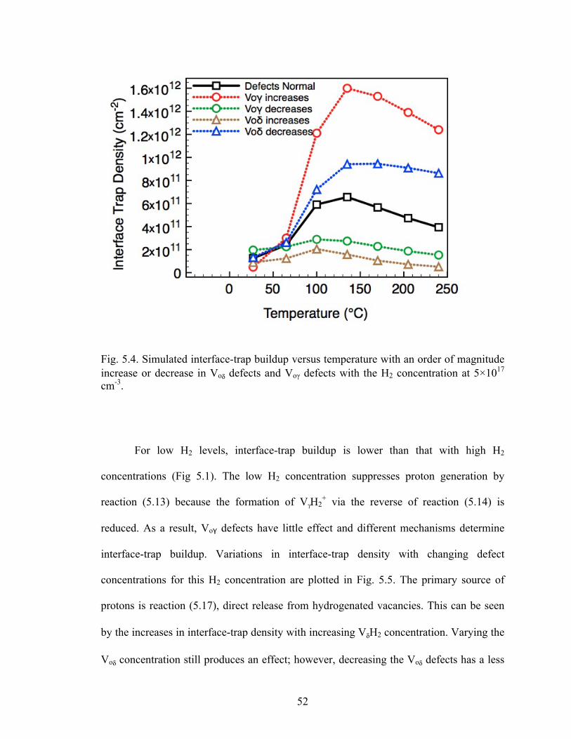
5.4 Simulated interface-trap buildup versus temperature with an order of magnitude
increase or decrease in Voδ defects and Voγ defects with the H2 concentration at 5×1017 cm-3. ...........................................................................................................52
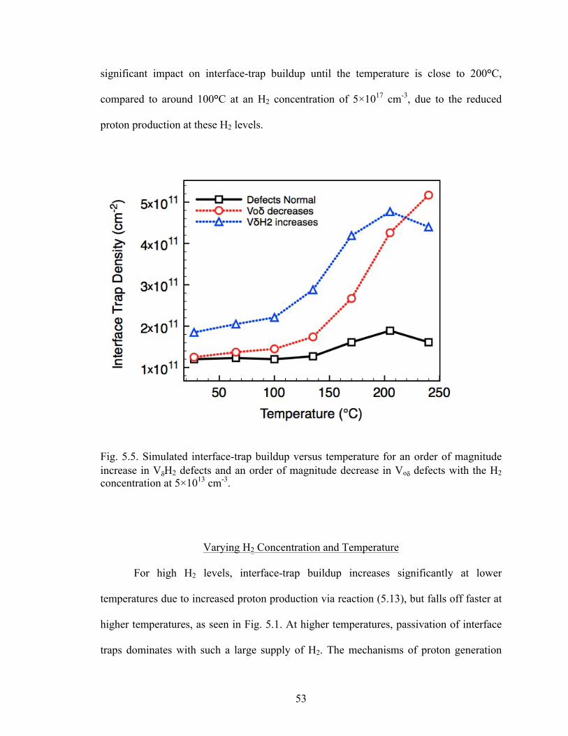
5.5 Simulated interface-trap buildup versus temperature for an order of magnitude
increase in VδH2 defects and an order of magnitude decrease in Voδ defects with the H2 concentration at 5×1013 cm-3. ......................................................................53
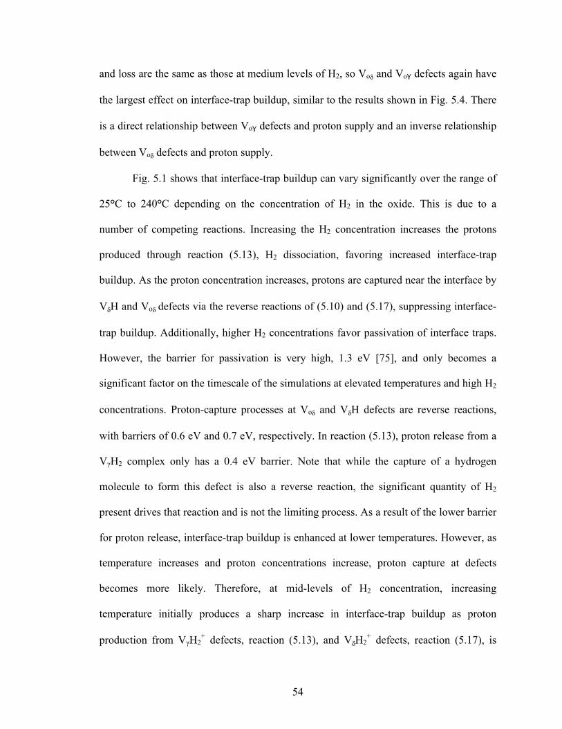
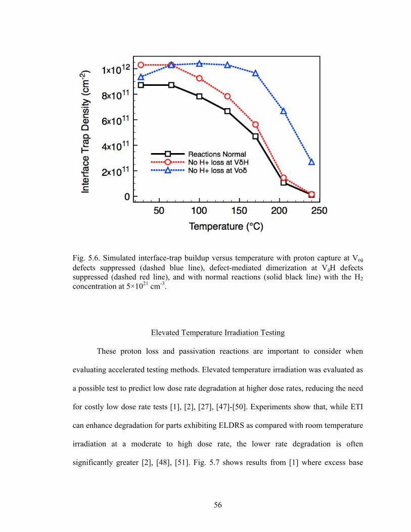
5.6 Simulated interface-trap buildup versus temperature with proton capture at Voδ
defects suppressed (dashed blue line), defect-mediated dimerization at VδH defects suppressed (dashed red line), and with normal reactions (solid black line) with the H2 concentration at 5×1021 cm-3. ..............................................................56
viii
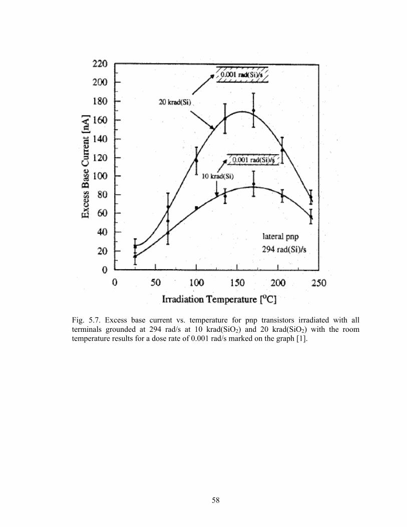
5.7 Excess base current vs. temperature for pnp transistors irradiated with all terminals grounded at 294 rad/s at 10 krad(SiO2) and 20 krad(SiO2) with the room temperature results for a dose rate of 0.001 rad/s marked on the graph [1]. .........58
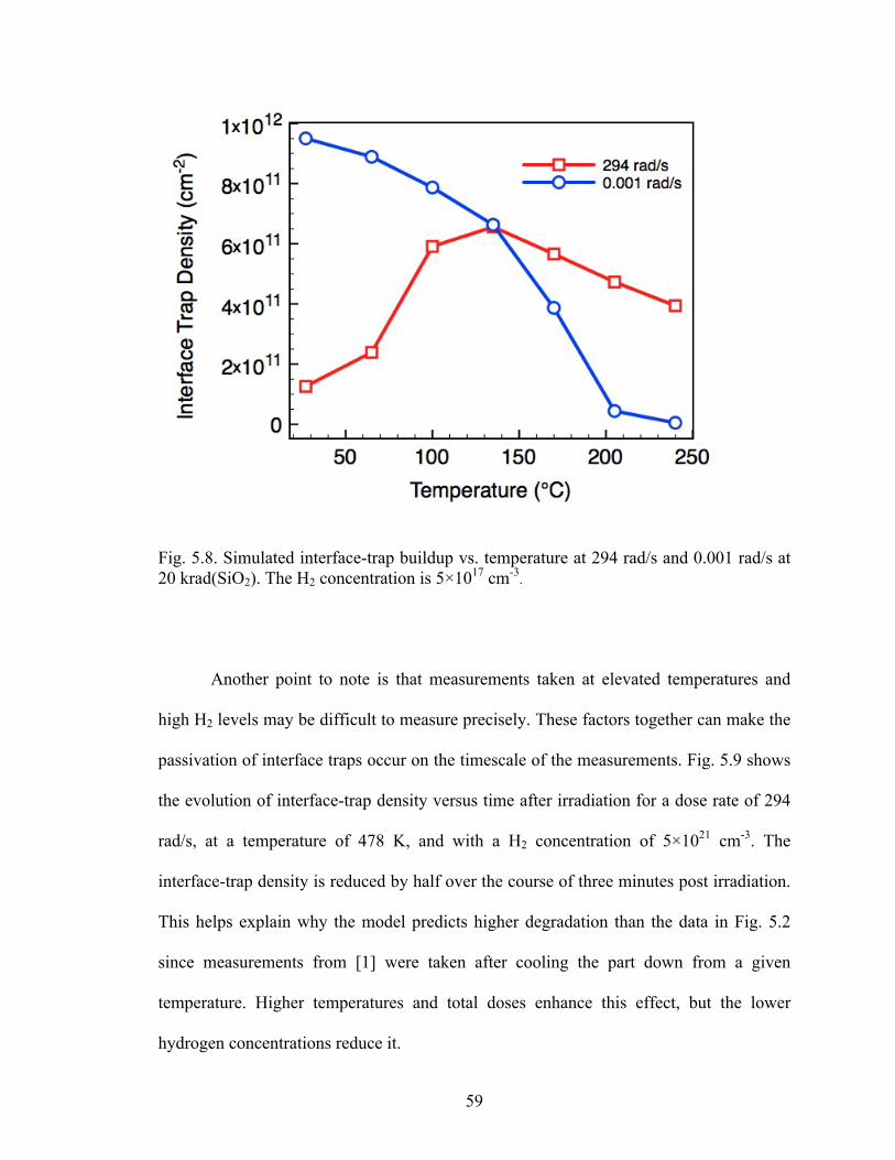
5.8 Simulated interface-trap buildup vs. temperature at 294 rad/s and 0.001 rad/s at 20
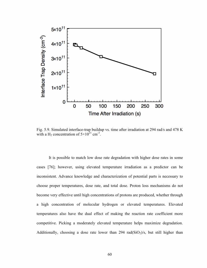
krad(SiO2). The H2 concentration is 5×1017 cm-3. .................................................59 5.9 Simulated interface-trap buildup vs. time after irradiation at 294 rad/s and 478 K
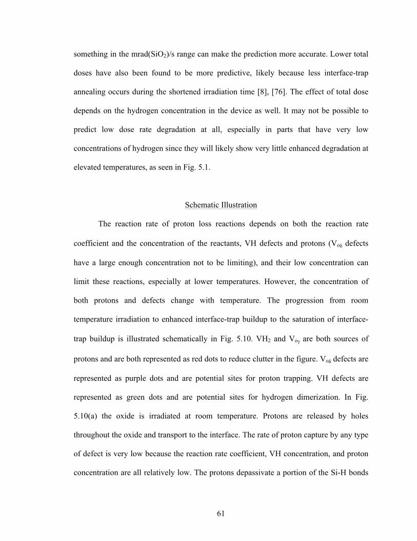
with a H2 concentration of 5×1021 cm-3. ................................................................60 5.10 Proton transport and interactions at or near the interface for room temperature and
elevated temperature. H+ is a proton, VH is a hydrogenated oxygen vacancy, VH2 is a doubly hydrogenated oxygen vacancy, Voδ is a dimer precursor oxygen vacancy, Voγ is a puckered precursor oxygen vacancy, O is a Si-H bond, X is an interface trap, and the size of the arrows are a rough approximation of the magnitudes of the reaction rate or speed of transport. (a) Oxide conditions at room temperature. (b) Oxide conditions at moderate temperature. (c) Oxide conditions at elevated temperatures. ........................................................................................63
1
CHAPTER I
INTRODUCTION
Radiation-induced interface traps are among the primary reliability concerns for
electronics in space. Extensive research has been done to understand the mechanisms
responsible for their creation and passivation. Experiments have documented the creation
of interface traps in both MOS and bipolar technologies under many conditions,
including varying temperatures [1], [2], ambient hydrogen concentrations [3]-[5],
processing conditions [6], and dose rates [7]. Identifying and understanding the effects of
the various conditions are critical for predicting how electronics will behave. Many
examples of this can be seen in the current literature. One of the primary examples is
Enhanced Low Dose Rate Sensitivity (ELDRS). ELDRS is a phenomenon where certain
parts, typically bipolar junction transistors, experience higher degradation at low dose
rates than at high dose rates [7]. This discovery prompted concerns about the radiation
testing done on Earth, which generally uses very high dose rates compared to what
electronics are exposed to in space. Understanding and predicting this enhanced
degradation are still ongoing topics of research [8]-[10]. Hydrogen plays a key role in
interface-trap formation and annealing and learning how it behaves is central to
understanding radiation response. The incorporation [11], introduction [4], transport [12],
and reactions [11], [13] of hydrogenous species in the oxide have been modeled to
provide insight into the mechanisms that lead to the buildup and annealing of radiation-
induced interface traps. These range from the two-stage model [14], [15] to explain basic
2
interface-trap formation, to more complex models involving competition between
electron-hole recombination and hydrogen release [16], [17] to explain dose rate effects.
Previous experiments investigating elevated temperature irradiation (ETI) have
shown both enhanced degradation and annealing effects, depending on the irradiation
temperature, dose rate, and total dose [1]. Recent first principles physics calculations
have provided significant insight into the reactions that can occur at some common
defects in oxides [11]. Proton release mechanisms and defect interactions under a variety
of conditions are identified that provide insight into enhanced degradation in the presence
of molecular hydrogen, irradiation at elevated temperatures, and dose rate effects. The
results demonstrate how proton loss reactions can limit the supply of protons at the
interface and suppress interface-trap buildup at elevated temperature [18].
Overview
Hydrogen produces variability in the radiation response of integrated circuits,
whether incorporated in the oxide or present in the surrounding environment as a gas.
The presence of molecular hydrogen can increase interface-trap buildup [4] and alter dose
rate response [19]. Defects with hydrogen incorporated in the oxide during processing
can suppress interface-trap buildup at elevated temperatures [18]. This thesis explores the
reactions of hydrogenous species at common oxide defects and the mechanisms that
explain radiation-induced interface-trap formation and annealing, focusing on the effects
of temperature, molecular hydrogen concentration, and dose rate. Density functional
theory (DFT) calculations [11] that identify defects likely to be present in common
thermal oxides and provide energy barriers for reactions at those defects are presented
3
and important mechanisms for interface-trap buildup and annealing are extracted and
discussed. These mechanisms are implemented in a numerical model that simulates
interface-trap buildup in a 1-D slice of oxide and silicon using the estimates for defect
concentrations and energy barriers from the DFT calculations. The results provide insight
into which reactions have a significant impact on interface-trap density under a variety of
conditions; the predictions are compared to experimental data.
Organization
This rest of the thesis investigates the physical processes responsible for interface-
trap buildup and annealing and how they are affected by various environmental
conditions.
Chapter II provides background on interface-trap creation. The defects and
reactions involved are presented, along with experimental observations on how dose rate,
temperature, and H2 affect interface-trap buildup and annealing. Previous modeling
efforts and mechanisms are discussed. Chapter III goes into greater detail about the
nature of the defects present in the oxide and the energetics of the reactions that occur
there. Mechanisms for interface-trap creation are presented based on first principles
physics calculations. Chapter IV takes the energy barriers provided by these calculations
and provides an analytical comparison of reactions at elevated temperatures that
demonstrates how reactions that remove protons from the oxide can become favorable,
limiting interface-trap buildup. Chapter V presents numerical simulations that implement
a detailed set of reactions at every defect considered in the physics calculations presented
in Chapter III. The results produce data similar to experimental observations and provide
4
a more physical understanding of how interface-trap buildup is affected by temperature,
dose rate, and molecular hydrogen concentration. Chapter VI concludes the thesis,
summarizing the key results and highlighting the advances in understanding. The
implications of these results are discussed.
5
CHAPTER II
INTERFACE TRAP FORMATION
Holes created by ionizing radiation may release hydrogen in the form of protons
that can transport to the interface and depassivate Si-H bonds, creating interface traps
[15]. This process depends on various defects in the oxide that facilitate hole transport
and act as reaction sites, as well as the various mobile species that are the reactants. Other
factors like dose rate, temperature, and molecular hydrogen concentration affect the
buildup and annealing of interface traps as well. Numerous experiments have been
performed and models created to investigate the defects and mobile species involved in
these processes. This chapter discusses how interface traps are formed, their effects, and
how their formation can be affected by other factors. The basic reactions and reactants
responsible for interface-trap formation are identified. Experimental observations of the
effects of dose rate, temperature, and H2 concentration are discussed, as well as some
approaches used to simulate interface-trap formation.
Interface Trap Creation
The mechanisms responsible for interface-trap creation have been extensively
studied. The consensus is that the dominant process is the depassivation of Si-H bonds at
the interface by protons released by holes generated by ionizing radiation [15]. Radiation
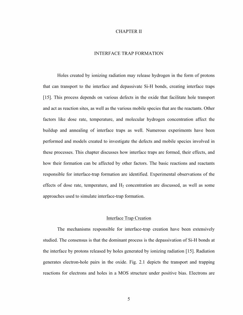
generates electron-hole pairs in the oxide. Fig. 2.1 depicts the transport and trapping
reactions for electrons and holes in a MOS structure under positive bias. Electrons are
6
transported toward the gate while holes are transported toward the interface. For bipolar
devices, the overall picture is similar, but without a gate providing positive bias, the
electric field is largely determined by work function differences and is much lower. This
results in lower charge yields since the electric field helps to separate holes and electrons
created by ionizing radiation before they recombine [15]. The low electric field also
means that the primary charge transport mechanism is diffusion instead of drift and that
there is increased chance that electrons can neutralize trapped holes before they can
release protons [17]. Additionally, space charge has a larger effect on the local fields and
can affect charge transport [20], [21]. Note that interface-trap buildup also occurs with
negative electric fields present and is likely due to hydrogen sources in the bulk silicon
[22]. This thesis primarily focuses on the low electric field case and considers how
hydrogen interactions in the oxide can affect radiation-induced interface-trap buildup.
The radiation-induced degradation depends on the hole yield, the number of holes that
escape recombination with electrons, which is determined primarily by the energy of the
radiation, the strength of the electric field in the oxide, and the initial concentration of
electron hole pairs [15]. Once holes are generated, they rapidly become trapped in
shallow traps and migrate via polaron hopping, moving from one trap to the next [15].
While holes are migrating through the oxide, they can interact with defect sites
containing hydrogen, releasing the hydrogen as protons H+ [15], [17]. Protons then are
transported to the interface where they can depassivate Si-H bonds, creating interface
traps via the following reaction:
H+ + Si-H → Si-+ + H2 . (2.1)
Si-+ is a dangling bond that can act as a recombination center, an interface trap.
7
Fig. 2.1. Schematic diagram of charge carrier generation, transport and interactions within SiO2. After [15].
ELDRS
The irradiation dose rate can have a significant effect on the radiation response of
some parts, causing increased degradation at a low dose rate compared to a higher dose
rate at the same total dose. Parts that show this increased degradation at low dose rates
are considered to exhibit Enhanced Low Dose Rate Sensitivity (ELDRS). ELDRS is a
major issue for linear bipolar transistors [23]-[25], especially since dose rates in space are
generally much lower than the dose rates used for testing parts on Earth; the search for a
general method to screen ELDRS-sensitive parts at higher dose rates is still ongoing.
8
Note that parts are only considered to exhibit ELDRS if they exhibit a true dose rate
effect, such that even if the high dose rate device is annealed at room temperature for the
same length of time as the irradiation at low dose rate, the degradation at low dose rate is
still greater. The relative increase in degradation from high dose rate plus anneal to low
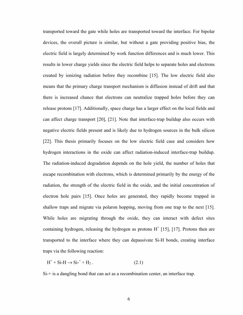
dose rate is called the true dose rate enhancement factor [26]. Fig. 2.2 shows an example
of enhancement factors versus dose rate for several types of bipolar ICs.
Fig. 2.2. Relative damage (enhancement factor) versus dose rate for several different bipolar ICs [7].
9
There are many theories to explain why ELDRS occurs. Some of the prominent
ones are briefly described here. It has been proposed that the space charge created in the
bulk of the oxide affects the transport of other charged species, reducing the number of
protons that arrive at the interface [27], [28]. It has also been suggested that the density of
defects that act as Shockley-Read-Hall recombination centers compared to the density of
defects that act as shallow hole traps is important since an increased availability of
recombination centers reduces the holes available to release protons [29]. The presence of
hydrogen, which can be released from the packaging [3] or be present in some part of the
device like the passivation layers [6], has also been shown to be an important factor in the
ELDRS response of bipolar devices [4], [19]. When ionizing radiation creates electron-
hole pairs, under positive bias, electrons are transported to the gate and holes are
transported to the interface. While migrating toward the interface, holes have a chance to
either recombine with electrons or release hydrogen from defects in the form of protons
that can migrate to the interface and create interface traps. Once a hole has transferred its
charge to a proton, it is unlikely to be neutralized by an electron, making this competition
between recombination and proton release key to the amount of degradation [17]. At high
dose rates when large concentrations of electrons and holes are present simultaneously,
more holes recombine with electrons, limiting the interface traps created by protons [17].
Introducing additional hydrogen increases the number of holes that release protons
instead of recombining with electrons, suppressing high dose rate effects and resulting in
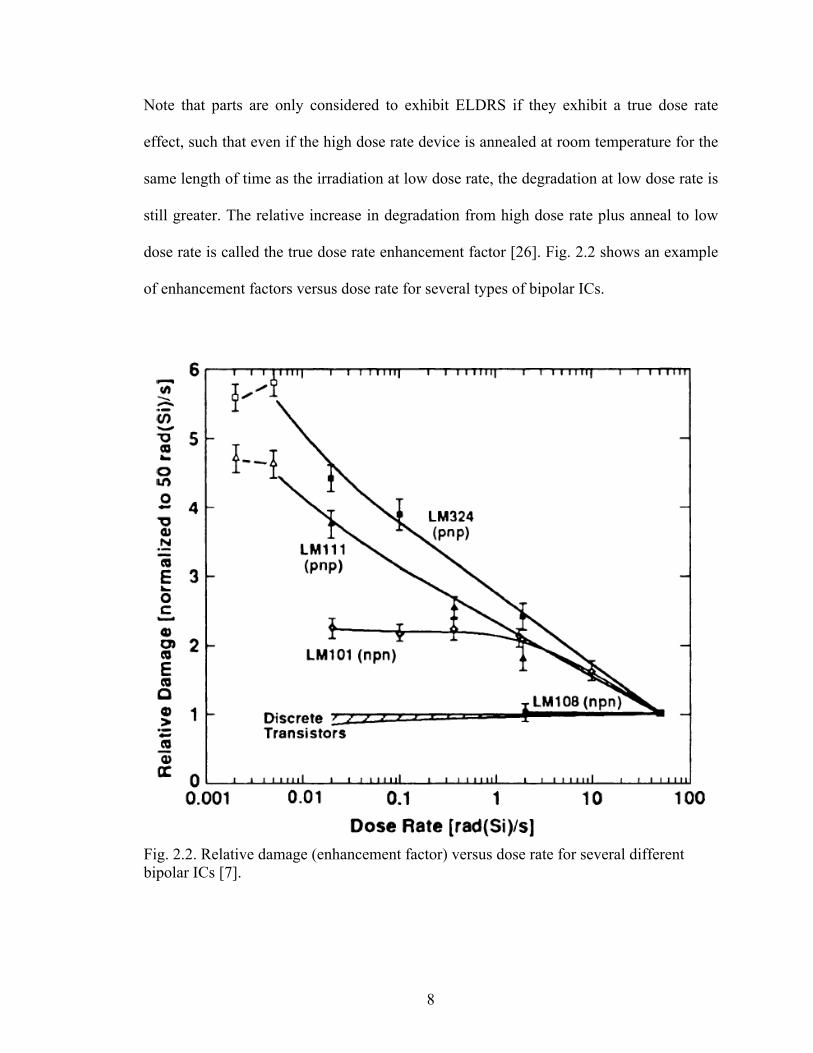
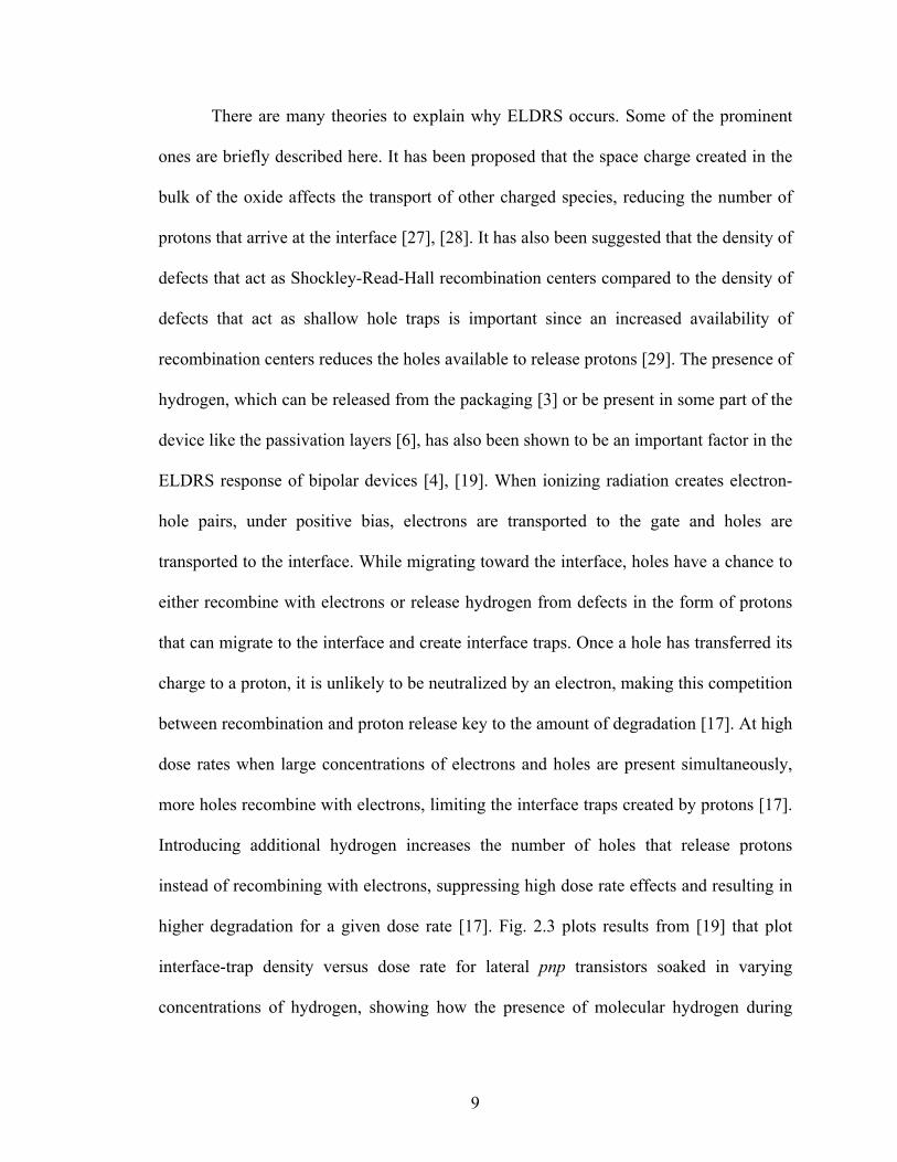
higher degradation for a given dose rate [17]. Fig. 2.3 plots results from [19] that plot
interface-trap density versus dose rate for lateral pnp transistors soaked in varying
concentrations of hydrogen, showing how the presence of molecular hydrogen during
10
irradiation not only increases interface-trap buildup, but also causes the dose rate at
which the transition between high and low dose rate degradation occurs to shift to higher
dose rates. ELDRS effects also depend on a number of other factors such as processing
Fig. 2.3. Interface-trap concentration versus dose rate for lateral pnp bipolar transistors irradiated to 30 krad(Si) in three different concentrations of molecular hydrogen [19].
Excess Base Current in Bipolar Transistors
It is useful to briefly discuss the effects of radiation-induced interface traps on
lateral pnp bipolar transistors because of the direct effect they have on excess base
current, making lateral pnp transistors common devices to provide a measure of interface-
trap buildup. The primary effect of total ionizing dose (TID) on lateral PNP bipolar
11
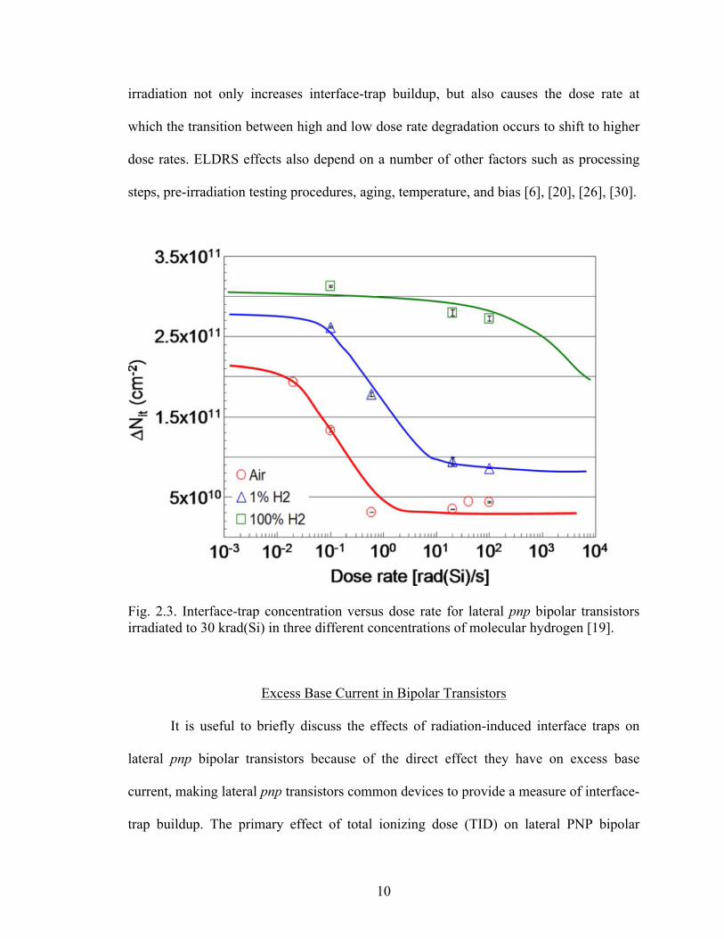
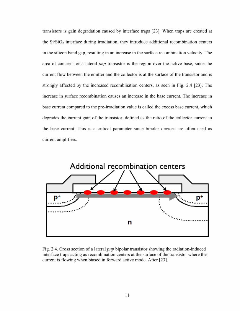
transistors is gain degradation caused by interface traps [23]. When traps are created at
the Si/SiO2 interface during irradiation, they introduce additional recombination centers
in the silicon band gap, resulting in an increase in the surface recombination velocity. The
area of concern for a lateral pnp transistor is the region over the active base, since the
current flow between the emitter and the collector is at the surface of the transistor and is
strongly affected by the increased recombination centers, as seen in Fig. 2.4 [23]. The
increase in surface recombination causes an increase in the base current. The increase in
base current compared to the pre-irradiation value is called the excess base current, which
degrades the current gain of the transistor, defined as the ratio of the collector current to
the base current. This is a critical parameter since bipolar devices are often used as
current amplifiers.
Fig. 2.4. Cross section of a lateral pnp bipolar transistor showing the radiation-induced interface traps acting as recombination centers at the surface of the transistor where the current is flowing when biased in forward active mode. After [23].
12
E’ Centers
When holes are created in the oxide, they can be trapped at defects and then either
react with another species in the oxide, or detrap from the defect and move to another
defect [15]. Numerous studies show that the defects with which holes primarily interact
are E’ defects [31]-[33], which are most likely oxygen vacancies (Vo) [34]. Experiments
[35] and theory [36] indicate that when a vacancy has trapped a hole it assumes either a
dimer or puckered configuration. Neutral oxygen vacancies are either dimer precursors
(Voδ) or puckered precursors (Voγ). Due to differences in the defect energy levels, holes
remain trapped at defects in the puckered configuration much longer than at defects in the
dimer configuration [11], [35]. Dimer precursors are more likely to mediate hole
transport, while puckered precursors tend to serve as reaction centers or fixed charge.
Hydrogen Enhanced Degradation
The presence of molecular hydrogen affects interface-trap density. If present near
the interface, molecular hydrogen can passivate interface traps, annealing the damage
[37]. However, ambient hydrogen enhances the degradation of several types of linear
bipolar devices when they are exposed to ionizing radiation [3], [4], [38] indicating that
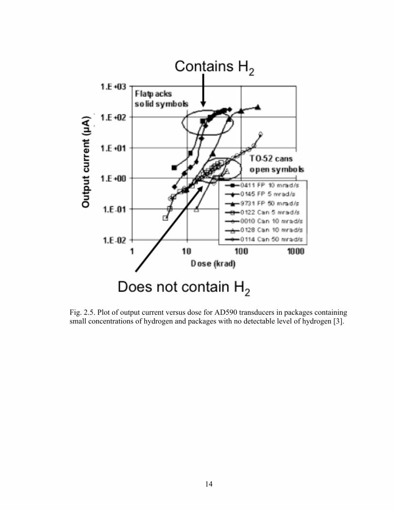
hydrogen is involved with both interface-trap buildup and annealing. In [3] the radiation
response of the AD590 temperature transducer varies based on the packaging of the
devices. Parts packaged in flat-packs show higher changes in output current, a sign of
increased degradation, than parts packaged in TO-52 cans [3], as shown in Fig. 2.5.
Residual gas analysis revealed that there was a small concentration of hydrogen present
13
in the flat-packs, but no detectable hydrogen concentration in the TO-52 cans, suggesting
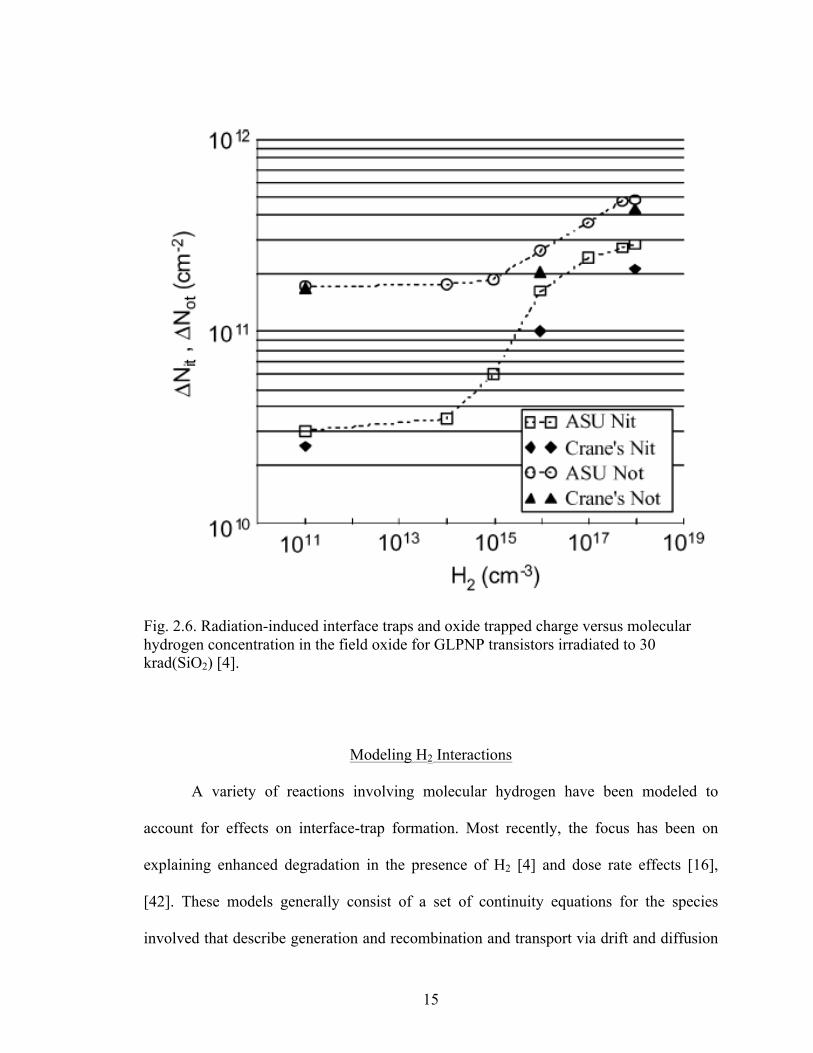
that hydrogen was responsible for the enhanced degradation [3]. In order to understand
the relationship between the presence of hydrogen and degraded radiation response of
bipolar devices, experiments were performed that soaked bipolar transistors prior to
irradiation in either varying concentrations of hydrogen [4] or 100% hydrogen
concentration for varying amounts of time [38]. Their radiation responses were then
compared at a given total dose. The results showed that, in both cases, the concentration
of radiation-induced interface traps and oxide trapped charge increased with the amount
of hydrogen present, as seen in Fig. 2.6. One of the mechanisms proposed for hydrogen
enhanced degradation is the cracking of H2 molecules at a charged defect, an E’ center
[39], [40]. Reactions between H2 molecules and oxide defects have been explored using
first principles physics calculations [38], [41]; however, there was no research on the
likelihood of the chosen defects being present in significant quantities in the oxides of the
real world devices.
14
Fig. 2.5. Plot of output current versus dose for AD590 transducers in packages containing small concentrations of hydrogen and packages with no detectable level of hydrogen [3].
15
Fig. 2.6. Radiation-induced interface traps and oxide trapped charge versus molecular hydrogen concentration in the field oxide for GLPNP transistors irradiated to 30 krad(SiO2) [4].
Modeling H2 Interactions
A variety of reactions involving molecular hydrogen have been modeled to
account for effects on interface-trap formation. Most recently, the focus has been on
explaining enhanced degradation in the presence of H2 [4] and dose rate effects [16],
[42]. These models generally consist of a set of continuity equations for the species
involved that describe generation and recombination and transport via drift and diffusion
16
and the effect of electric field. There have been a variety of approaches. In [4], Chen et
al. use an analytical model to relate hydrogen exposure to enhanced interface-trap
formation by suggesting H2 cracks at a defect in the oxide, creating more potential
reaction sites for holes to release protons. This matched the data shown in Fig. 2.6. This
model assumes the presence of a processing defect that reacts with H2 to form defects
that release protons in the presence of holes created during irradiation. Batyrev et al. [38]
also attempt to explain hydrogen-enhanced degradation, this time numerically simulating
a set of reactions that incorporate first principles physics calculations into some of the
reaction rate calculations. This model also assumes that H2 molecules react at neutral
defects, presumed to be oxygen vacancies in this paper, and that holes then release
protons from the resulting hydrogenated defect. Electrons are assumed to exit the oxide
quickly and the effects of recombination are ignored except for the calculation of the
initial hole yield during irradiation. Chen et al. [42] simulate the dose rate response by
modifying the electron-hole recombination rate directly since it changes as increasing
hydrogen concentration creates a competition between recombination and proton release.
While including the effects of recombination, no specific reactions are implemented,
simply a recombination term representing the effective electron-hole recombination.
Again, proton release is considered to be due to a hole reacting at a hydrogenated defect,
the concentration of which is adjusted to account for changes in concentration of
molecular hydrogen. All of the models presented thus far did not include terms to account
for reverse reactions. Hjalmarson et al. [16] simulated dose rate variations differently,
describing a set of bimolecular reactions between a number of potential defects and
mobile species. Transport parameters are specific to each mobile species. This model
17
considers both proton release from hydrogenated defects and the dissociation of
molecular hydrogen at positively charge defects and accounts for reverse reactions.
Reaction rate coefficients are not unique; one value was used for reactions involving
uncharged species and a second was used for reactions involving charged species.
Rowsey et al. [43] implement reactions based on first principles physics calculations that
calculate forward and reverse reaction rates for each reaction. Some reactions are
simplified, describing the capture and subsequent release of a mobile species at a defect
in one reaction using a single forward and reverse energy barrier. In this thesis a model is
presented that calculates forward and reverse reaction rates based on DFT calculations
that take intermediate steps in each reaction into account. This allows multiple reaction
pathways that can have different energy barriers. Transport parameters and reaction rates
are affected by temperature in this model, providing insight into which mechanisms are
important at different temperatures.
Density Functional Theory Calculations
The mechanisms of interface-trap buildup and annealing depend on reactions
involving hydrogen at various point defects. In order to develop more accurate models,
first principles physics calculations are used that describe these reactions at an atomic
level. Previously, reactions involving hydrogen have been studied with a variety of
theoretical calculations. Estimates of reaction energies were calculated using semi-
empirical molecular orbital theory [44]. Next, cluster models of the oxide were used,
involving a cluster of atoms to describe a defect based on α-quartz structure. Results for
point defects are applied to amorphous silicon dioxide because the local structure does
18
not depend significantly on long-range order [45]. Later calculations used periodic
supercells with α-quartz and amorphous configurations [46]. However, these studies
explored a limited number of defects and did not address a comprehensive set of defects
that are actually found in device quality oxides.
Elevated Temperature Irradiation (ETI)
Experiments in which bipolar transistors are irradiated at elevated temperatures at
moderate to high dose rates show that the gain degradation attributed to interface-trap
buildup is enhanced compared to irradiations at room temperature [27], [47], [48]. This is
of interest because these bipolar transistors also exhibit ELDRS, showing more interface-
trap buildup at a given total dose when the devices are irradiated at low dose rates than at
high dose rates [27], [49]. Elevated temperature irradiation was evaluated as a possible
test to predict low dose rate degradation at higher dose rates [1], [2], [27], [47], [48]-[50].
The reason that ELDRS testing is of so much concern is because space is a low-dose-rate
environment and dose rates commonly used on Earth to test parts are significantly higher.
In response to this, parts that may exhibit ELDRS must be tested at a low dose rate or
undergo a test designed to accelerate radiation-induced degradation and simulate low-
dose-rate effects. Testing at a low dose rate is usually undesirable because such testing
may take many months. However, while ELDRS has been documented for more than
twenty years, no completely satisfactory accelerated hardness assurance test has been
identified.
It is hypothesized that ETI accelerates the movement of charge and mitigates
space charge effects that are often observed in linear bipolar devices and integrated
19
circuits irradiated at high dose rates at room temperature [20], [27]. Experiments show
that, while ETI can enhance degradation for ELDRS sensitive parts as compared with
room temperature irradiation at a moderate to high dose rate, the lower rate degradation is
often significantly greater [2], [48], [51]. Additionally, ETI only enhances degradation up
to certain temperatures, above which degradation is reduced instead of enhanced [1],
[50]. This reduction is attributed to enhanced annealing at high temperatures [1], [50], but
the physical mechanisms of these processes are not well understood. Additionally, it is
found that high temperature annealing after irradiation can cause significant recovery,
reinforcing that high temperatures can improve the radiation response of devices and
involve different mechanisms than ELDRS [52]. These results demonstrated that while
ETI irradiation may correctly produce low-dose-rate degradation in some cases, there is
significant variability in the radiation response among parts. Thus, understanding the
physical mechanisms at work during low dose irradiation and elevated temperature
irradiation is important for evaluating the radiation hardness of parts and assessing the
effectiveness of accelerated test methods.
20
CHAPTER III
HYDROGEN INTERACTIONS WITH COMMON OXIDE DEFECTS
In order to determine potential interface-trap formation and annealing
mechanisms applicable to real world oxides, first principles physics calculations were
performed to determine the most likely defects to be present in device-quality oxides and
explore the reactions that occur at those sites [11]. The energetics of hydrogen
interactions at a variety of defects are considered. Based on these energies, mechanisms
for proton generation from the direct release of a proton at a defect via a hole and the
dissociation of molecular hydrogen at positively charged defects are formulated.
Oxygen Vacancy Formation
Oxygen vacancies in silicon dioxide facilitate hydrogen and hole transport and act
as reaction sites [34]. Defect interactions are modeled in a cube of silicon dioxide with an
edge length of 1.2 nm, a large enough volume to model hydrogen interactions with
defects in a bulk oxide [11]. In this model, the oxygen vacancy defects are created by
removing an oxygen atom and letting the structure relax, resulting in a stretched Si-Si
bond [11]. The formation energy is calculated by comparing the energy of the fully
relaxed structure to the normal bulk model with no defects [11]. The formation energies
of over one hundred oxygen vacancies have been computed and are found to be
correlated with the length of the stretched Si-Si bond [53], [54], as seen in Fig. 3.1.
Vacancies with lower formation energy are much more likely to form and are present in
21
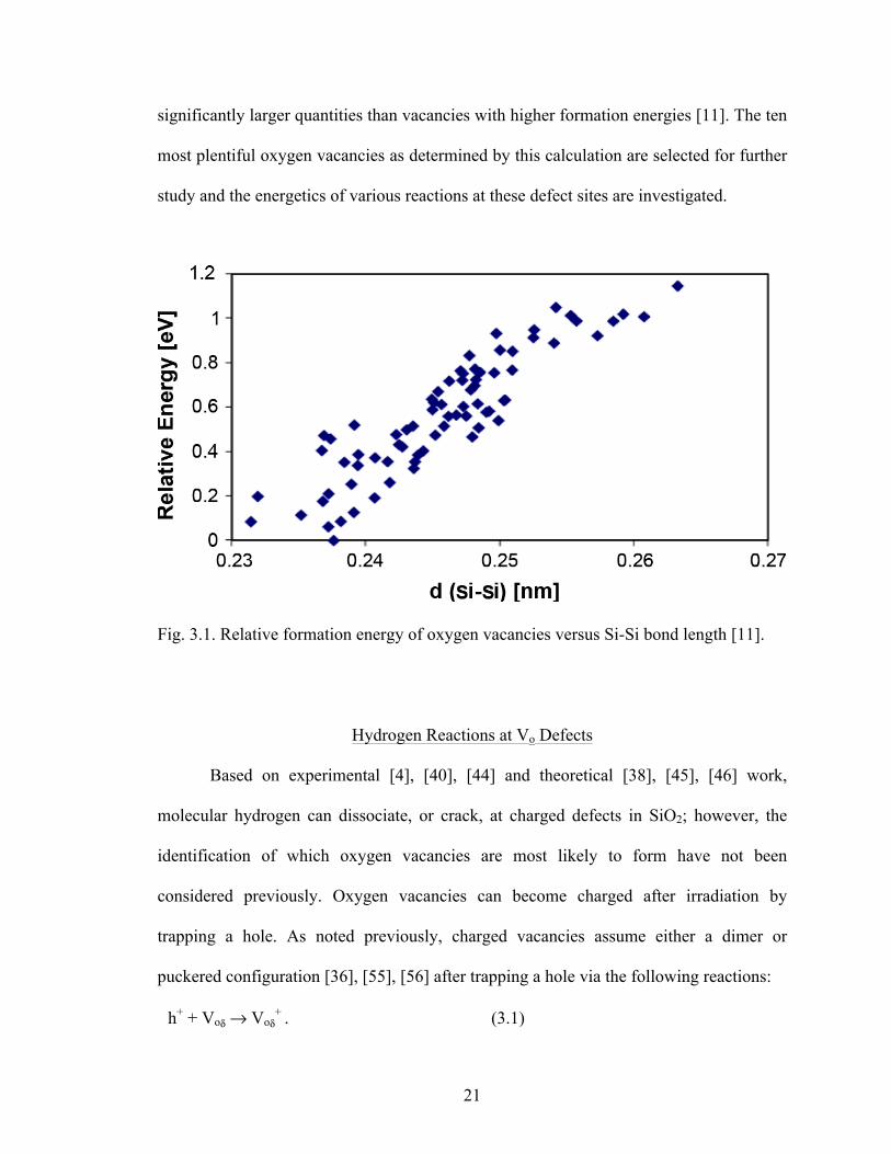
significantly larger quantities than vacancies with higher formation energies [11]. The ten
most plentiful oxygen vacancies as determined by this calculation are selected for further
study and the energetics of various reactions at these defect sites are investigated.
Fig. 3.1. Relative formation energy of oxygen vacancies versus Si-Si bond length [11].
Hydrogen Reactions at Vo Defects
Based on experimental [4], [40], [44] and theoretical [38], [45], [46] work,
molecular hydrogen can dissociate, or crack, at charged defects in SiO2; however, the
identification of which oxygen vacancies are most likely to form have not been
considered previously. Oxygen vacancies can become charged after irradiation by
trapping a hole. As noted previously, charged vacancies assume either a dimer or
puckered configuration [36], [55], [56] after trapping a hole via the following reactions:
h+ + Voδ → Voδ+ . (3.1)
22
h+ + Voγ → Voγ+ . (3.2)
Voδ and Voγ are precursors for the dimer (Voδ+) and puckered (Voγ
+) configurations. The
possible reactions of H2 at both of these defects are considered.
H2 interactions with the positively charged dimer defect have been studied
experimentally with electron paramagnetic resonance (EPR) [57], [58] and theory [59],
[60]. The cracking reaction at this defect is:
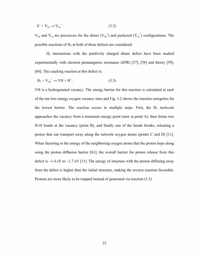
H2 + Voδ+ → VH + H+ . (3.3)
VH is a hydrogenated vacancy. The energy barrier for this reaction is calculated at each
of the ten low-energy oxygen vacancy sites and Fig. 3.2 shows the reaction energetics for
the lowest barrier. The reaction occurs in multiple steps. First, the H2 molecule
approaches the vacancy from a minimum energy point (now at point A), then forms two
Si-H bonds at the vacancy (point B), and finally one of the bonds breaks, releasing a
proton that can transport away along the network oxygen atoms (points C and D) [11].
When factoring in the energy of the neighboring oxygen atoms that the proton hops along
using the proton diffusion barrier [61], the overall barrier for proton release from this
defect is ~1.4 eV to ~1.7 eV [11]. The energy of structure with the proton diffusing away
from the defect is higher than the initial structure, making the reverse reaction favorable.
Protons are more likely to be trapped instead of generated via reaction (3.3).
23
Fig. 3.2. Reaction energies for the dissociation of H2 at a positively charged oxygen vacancy in the dimer configuration [11]. Points A, B, C, and D are referred to in the text.
The cracking of H2 at positively charged oxygen vacancies in the puckered
configuration is also considered. The concentration of these defects is believed to be
roughly an order of magnitude lower than Voδ defects [53], [54], [55] and two out of the
ten vacancies selected for these calculations form a puckered defect [11], results similar
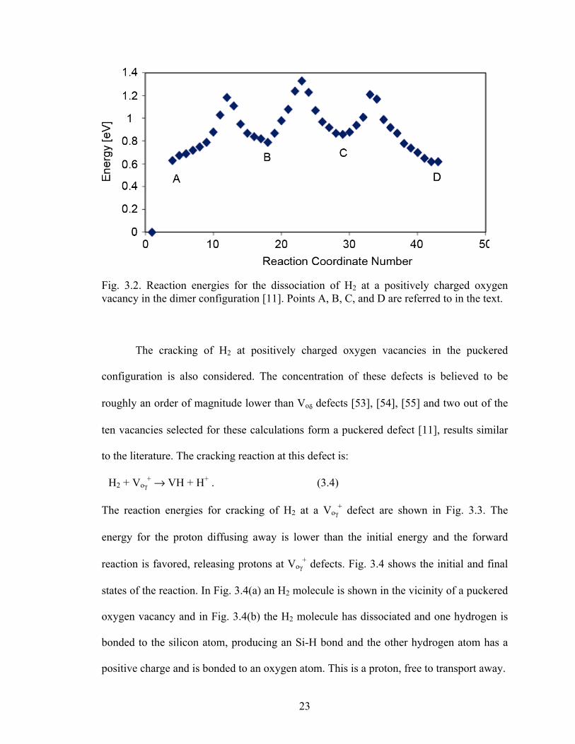
to the literature. The cracking reaction at this defect is:
H2 + Voγ+ → VH + H+ . (3.4)
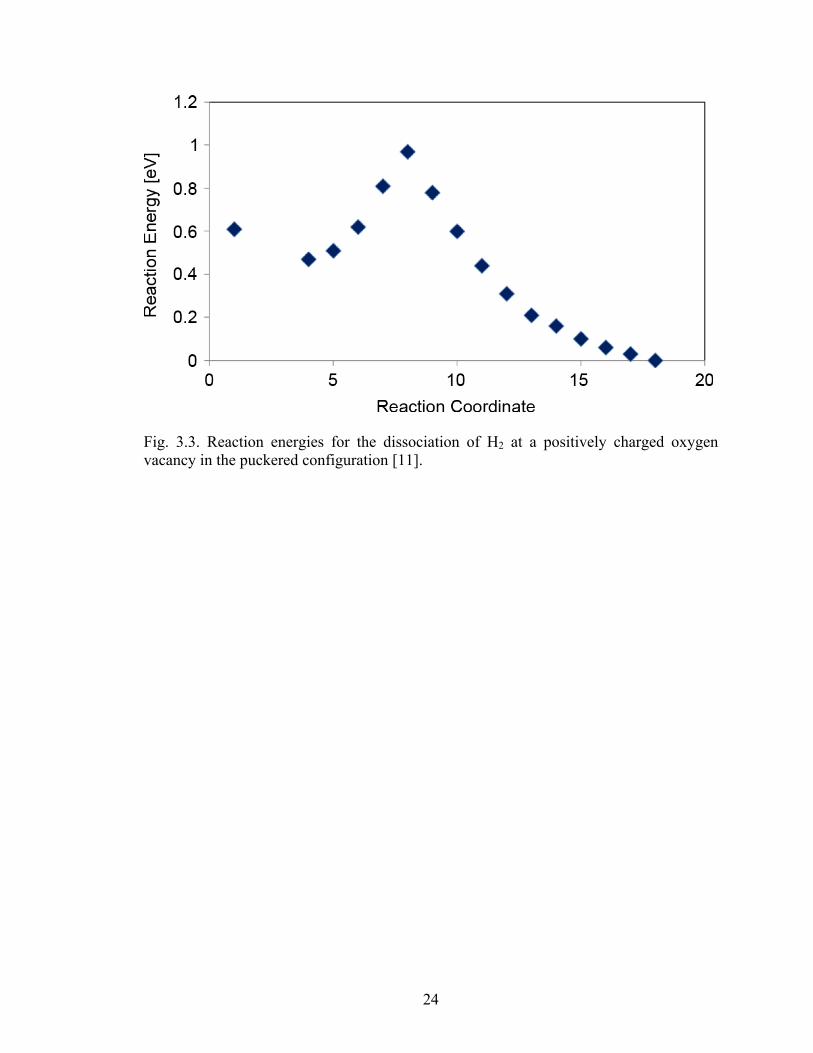
The reaction energies for cracking of H2 at a Voγ+ defect are shown in Fig. 3.3. The
energy for the proton diffusing away is lower than the initial energy and the forward
reaction is favored, releasing protons at Voγ+ defects. Fig. 3.4 shows the initial and final
states of the reaction. In Fig. 3.4(a) an H2 molecule is shown in the vicinity of a puckered
oxygen vacancy and in Fig. 3.4(b) the H2 molecule has dissociated and one hydrogen is
bonded to the silicon atom, producing an Si-H bond and the other hydrogen atom has a
positive charge and is bonded to an oxygen atom. This is a proton, free to transport away.
24
Fig. 3.3. Reaction energies for the dissociation of H2 at a positively charged oxygen vacancy in the puckered configuration [11].
25
Fig. 3.4. (A) An H2 molecule near a Voγ+ defect. In (B) the H2 has split into a Si-H bond
and an O-H+ bond [11].
26
Proton Generation at High and Low Concentrations of Molecular Hydrogen
The reaction energies calculated in [11] are implemented in a 1-D model of
silicon dioxide and silicon to study the proton generation caused by the various reactions
under investigation. These simulations are performed using a simplified version of the
model described in greater detail later. The cracking of H2 at Voγ+ defects produce a
significant concentration of protons at high concentrations of H2, helping to explain the
increase in interface-trap buildup seen in Fig. 2.6. In the absence of excess H2 in the
oxide, radiation still produces interface traps. For this case, the release of protons via
holes from hydrogenated defects is considered.
Holes can interact with hydrogenated vacancies in the oxide and release hydrogen
as protons. Initially, singly hydrogenated vacancies were considered due to the low
energy barrier for proton release, ~0.4 eV. This occurs via the following reaction:
h+ + VH → Vo + H+ . (3.5)
However, the concentration of VH defects is roughly two orders of magnitude lower than
that of dimer oxygen vacancy precursors, and this reaction does not impact the proton
concentration significantly, even at low concentrations of H2. The simulations were then
expanded to include doubly hydrogenated vacancies. These VH2 defects have a slightly
larger barrier for proton release (~0.6 eV), but are expected to be present in
concentrations ten times larger than VH defects. When holes arrive at VH2 sites, they can
release a proton according to the following reaction:
h+ + VH2 → VH + H+ . (3.6)
This reaction significantly increases the proton concentration when low concentrations of
H2 are present, providing a mechanism for proton production in the absence of excess
27
molecular hydrogen. Note that the hydrogenated defects referred to in this section are
dimer precursors. Puckered vacancy precursors are present at one tenth of the
concentration of dimer vacancy precursors.
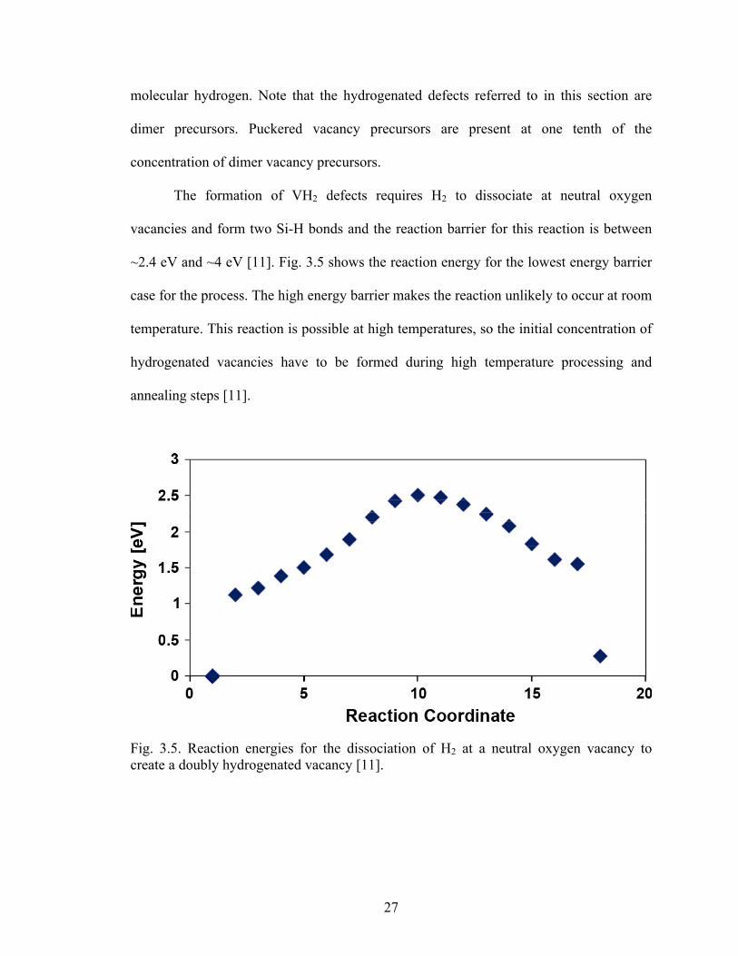
The formation of VH2 defects requires H2 to dissociate at neutral oxygen
vacancies and form two Si-H bonds and the reaction barrier for this reaction is between
~2.4 eV and ~4 eV [11]. Fig. 3.5 shows the reaction energy for the lowest energy barrier
case for the process. The high energy barrier makes the reaction unlikely to occur at room
temperature. This reaction is possible at high temperatures, so the initial concentration of
hydrogenated vacancies have to be formed during high temperature processing and
annealing steps [11].
Fig. 3.5. Reaction energies for the dissociation of H2 at a neutral oxygen vacancy to create a doubly hydrogenated vacancy [11].
28
In the presence of low concentrations of molecular hydrogen, proton generation is
mainly due to the release of protons from doubly hydrogenated oxygen vacancies created
during processing. When high concentrations of molecular hydrogen are present, proton
generation is enhanced by the dissociation of H2 at positively charged oxygen vacancies
in the puckered configuration. Rowsey et al. [43] implement these mechanisms along
with hole and electron capture and recombination at these defects and successfully
simulate both interface-trap buildup that matches experimental data of hydrogen
enhanced degradation and dose rate effects at varying concentrations of H2. These results
are shown in Figs. 3.6 and 3.7.
The mechanisms identified by this study explain how interface traps are formed at
high and low concentrations of molecular hydrogen. The specific defects involved in
these mechanisms are identified, providing a more physical understanding of the
processes. The simulation results presented in Figs. 3.6 and 3.7 illustrate the robustness
of these reactions in describing interface-trap formation under different conditions and
explaining experimental results showing enhanced interface-trap buildup in the presence
of hydrogen and changes in dose rate behavior.
29
Fig. 3.6. Simulation results compared to experimental data from [4] showing interface-trap buildup as a function of molecular hydrogen concentration [43].
30
Fig. 3.7. Simulation results compared to experimental data from [19] showing interface-trap buildup as a function of dose rate for three different concentrations of molecular hydrogen concentration [43].
31
CHAPTER IV
PROTON LOSS AT ELEVATED TEMPERATURES - ANALYTICAL MODEL
Insights from the DFT calculations can be applied to studies investigating
radiation response at elevated temperatures to help understand the enhanced interface-
trap buildup and annealing that can occur under those conditions. In this chapter the
effects of elevated temperature irradiation (ETI) are approached analytically. This
analysis considers one of the proton loss mechanisms and compares the reaction rate
coefficient of hydrogen dimerization at VH defects with proton release from VH2 defects.
The results indicate that reverse reactions become favorable at elevated temperatures that
remove protons from the oxide and limit interface-trap formation. This forms the
foundation for more in-depth numerical simulations of elevated temperature behavior.
Experimental Observations
ETI experiments show that the concentration of radiation-induced interface traps
at a given dose rate depend on both the irradiation temperature and total dose [1]. In
experiments by Witczak et al., shown in Fig. 4.1 [1], increasing irradiation temperature
initially increases the excess base current of lateral pnp transistors, which is directly
related to interface-trap buildup in these devices [62]. At even higher irradiation
temperatures, however, the observed degradation can saturate or even decrease. The total
dose dependence of the device response during these experiments is illustrated in Fig. 4.2
[1]. For a given total dose, the degradation increases with temperature until it reaches a
32
maximum, and then decreases with further increases in temperature. The transition from
degradation to recovery occurs at lower temperatures for increasing total dose.
Fig. 4.1. Excess base current for a lateral PNP transistor as a function of total dose for seven different irradiation temperatures [1].
33
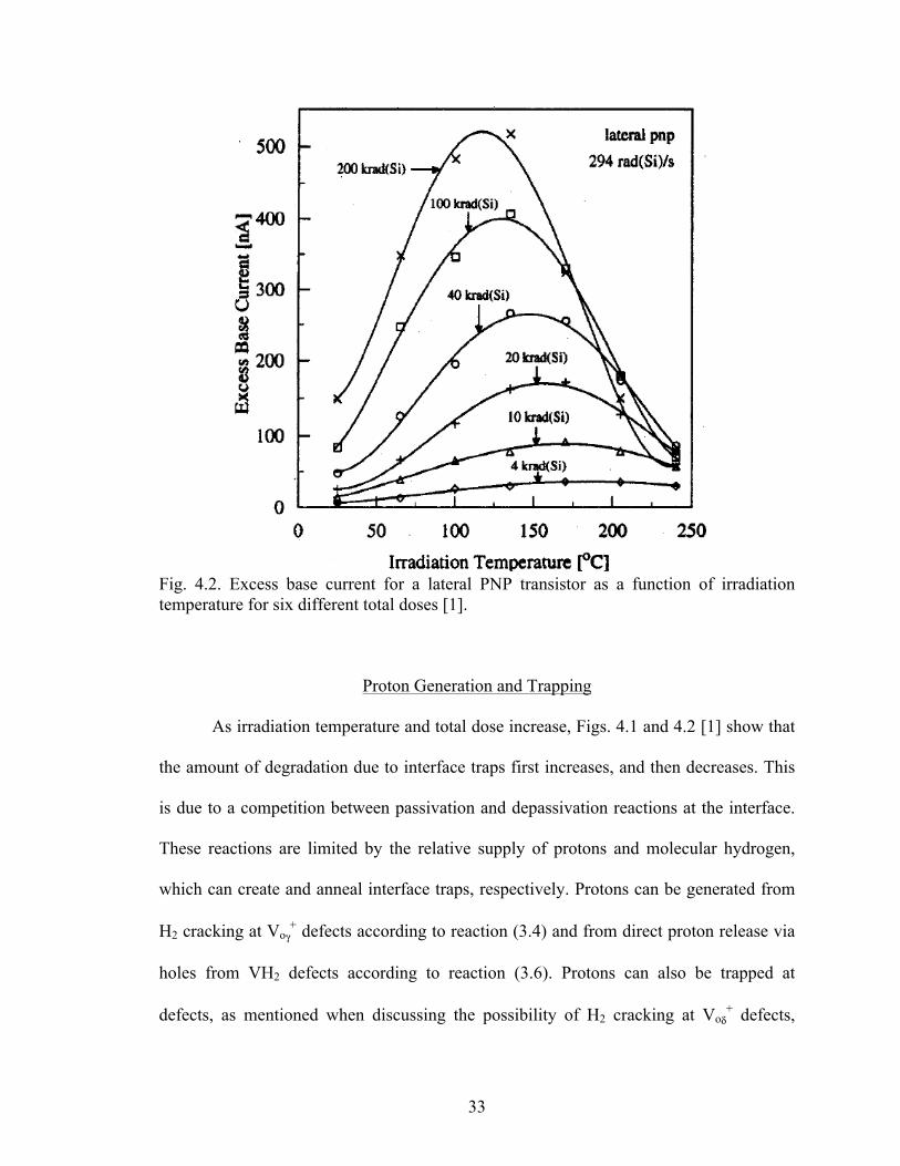
Fig. 4.2. Excess base current for a lateral PNP transistor as a function of irradiation temperature for six different total doses [1].
Proton Generation and Trapping
As irradiation temperature and total dose increase, Figs. 4.1 and 4.2 [1] show that
the amount of degradation due to interface traps first increases, and then decreases. This
is due to a competition between passivation and depassivation reactions at the interface.
These reactions are limited by the relative supply of protons and molecular hydrogen,
which can create and anneal interface traps, respectively. Protons can be generated from
H2 cracking at Voγ+ defects according to reaction (3.4) and from direct proton release via
holes from VH2 defects according to reaction (3.6). Protons can also be trapped at
defects, as mentioned when discussing the possibility of H2 cracking at Voδ+ defects,
34
reaction (3.3). These results indicate that it is energetically favorable for a proton to
arrive at a hydrogenated vacancy, bond with the other hydrogen atom, and diffuse away
as molecular hydrogen, leaving behind a positively charged oxygen vacancy [11]. This
analysis considers the capture of protons at VH defects:
H+ + VH → Voδ+ + H2 . (4.1)
This process is referred to as hydrogen dimerization, i.e., when two atomic hydrogens
combine to form molecular hydrogen. In this case one atom is the free moving proton and
the other atom is part of a Si-H bond. If this reaction works efficiently, it has a large
effect on the interface-trap density. Protons are neutralized in the reaction, something that
is very unlikely to occur directly due to a small electron capture cross section [17], and
the remaining positive charge is at a shallow trap, which has a much larger cross section
for electron capture [17].
Reaction Rates
The competition between proton generation and recombination determines how
many protons can reach the interface and create interface traps. The effects of proton
release at VH2 defects (3.6) and hydrogen dimerization at VH defects (4.1) on the proton
concentration can be compared by examining the proton continuity equation:
![H!]!"
= !! h! VH2 − !! H! VH − ∇ ∙ !!!.(4.2)
Here k1 and k2 are reaction rate coefficients and fH+ is the proton flux (number per unit
area per unit time). The first term is the reaction rate for proton release, which depends on
k1, the concentration of holes, and the concentration of VH2 defects. The second term is
the reaction rate for dimerization, which depends on k2 and the concentrations of protons
35
and VH defects. Increases in the reaction rate for proton release increase the proton
concentration in the oxide. Increases in the reaction rate for dimerization decrease the
proton concentration and increase the H2 concentration. Both the reaction rate
coefficients and the reactant concentrations change with temperature.
The initial increase in interface-trap density with temperature in the bipolar base
oxides reported in Figs. 4.1 and 4.2 occurs primarily because of the increase in proton
concentration as the reaction rate for proton release at VH2 defects via holes (3.6)
increases. As the temperature increases, the reaction rate coefficient for proton release, k1,
increases, generating protons more rapidly. The equation for an arbitrary reaction rate
coefficient of this type is given by:
kn = Lc× D × exp(−Eb/kBT). (4.3)
where Lc is the capture length of the defect, D is the diffusivity of the diffusing species,
Eb is the reaction barrier, kB is the Boltzmann constant, and T is the temperature. For
proton release, the holes are the diffusing species, and for dimerization protons are the
diffusing species. The DFT calculations already account for the diffusion barrier, so that
must be subtracted in order to obtain the energy barrier. In addition to the temperature
dependence of the energy barrier term, the diffusivity also depends exponentially on
temperature:
D = D0 × exp(−Ed/kBT). (4.4)
Here D0 is a constant and Ed is the diffusion energy. As temperature increases, the values
of the energy barrier exponential and the diffusivity increase, accelerating the reaction.
Increases in temperature increase the effective charge yield by reducing space charge
effects, which cause enhanced electron-hole recombination in SiO2 [27], increasing the
36
reaction rate as well. Proton diffusivity also increases with temperature, hastening
transport to the interface. The combination of a higher rate of proton release and higher
mobility for protons results in increased interface-trap creation with increasing
temperature.
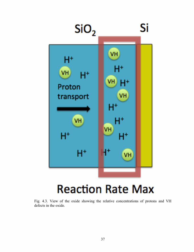
As temperature increases further, interface-trap buildup slows and even decreases
as the total dose (and thus the irradiation time) increases. As stated before, interface-trap
density is affected by the relative supply of protons and molecular hydrogen near the
interface, so the first notable observation is that the maximum reaction rate for proton
dimerization is near the interface. This is because the reaction rate in (4.3) depends on the
concentration of protons and VH defects, both of which are greatest near the interface.
Protons build up there as they are released in the bulk oxide, and VH defects increase
there as well. This is because VH defects naturally comprise a percentage of the oxygen
vacancy defects after typical device processing [11], and the concentration increases near
the interface along with the concentration of oxygen vacancies [63]. This is illustrated in
Fig. 4.3.
37
Fig. 4.3. View of the oxide showing the relative concentrations of protons and VH defects in the oxide.
38
Note that Voδ defects are also potential trapping sites for protons and the same logic about
near interfacial concentration increase applies to those defects as well.
Competing Reactions at Elevated Temperatures
Increases in the rate of dimerization favor annealing reactions by decreasing the
proton concentration and increasing the H2 concentration. According to (4.3), the reaction
rate coefficient increases with temperature because of the energy barrier exponential and
the diffusivity. The energy barrier provided by the DFT calculations includes the
diffusion barrier for the diffusing species, which must be subtracted because the diffusion
energy is already accounted for in the diffusivity term, as seen in (4.4). The calculated
barrier for dimerization is ~0.8 eV [11], and the diffusion energy of protons is also 0.8 eV
[64]-[66], so hydrogen dimerization occurs at VH defects without a barrier. This means
that the temperature dependence of the reaction rate coefficient is completely due to
changes in the diffusivity of protons. The barrier for proton release is ~0.5 eV [43],
however, there have been many numbers reported for the activation energy for hole
transport and the actual value varies based on factors like the electric field and oxide
quality [67]. For the purposes of this analysis, a value of 0.4 eV is used, taken from [68].
The difference is only 0.1 eV, so the majority of the temperature dependence on the
reaction rate coefficient for proton release is due to changes in the diffusivity of holes.
Direct dimerization of two neutral atomic hydrogen atoms (forming H2) has been
proposed as a mechanism to limit interface-trap buildup at high dose rates [13]. However,
there is little evidence that neutral atomic hydrogen exists in significant quantities in the
oxide at or above room temperature, and other mechanisms involving competition
39
between proton release and electron–hole recombination have also been invoked to
explain ELDRS [16], [17]. The calculations of [11] show that a dimerization reaction
involving protons can occur at a VH defect. However, at room temperature this reaction
is not very efficient and few protons react at VH defects. The efficiency of hydrogen
dimerization is determined by the second term in (4.2), the reaction rate. The reaction rate
increases with temperature as both the reaction rate coefficient and the proton
concentration increase. The temperature dependent terms of the reaction rate coefficient
are the energy barrier exponential and the diffusivity, which can be seen in (4.3) and
(4.4). The changes in these terms with temperature are different for proton release and
hydrogen dimerization and contribute to the change from enhanced degradation to
enhanced annealing seen in Figs. 4.1 and 4.2.
As noted previously, the diffusivity of protons and holes show the most variability
with temperature. For proton release, the diffusing species are holes, and for hydrogen
dimerization the diffusing species are protons. The diffusivity has an exponential
dependence on temperature, as seen in (4.4). The activation energy for proton transport is
~0.8 eV [62], [64], [66], [68]. For holes, there have been many numbers reported and the
actual value varies based on factors like electric field and oxide quality [67]. We use a
value of 0.4 eV for this analysis, taken from [69]. Rashkeev et al. [12] use drift-diffusion
modeling for hole transport and a range of effective mobility values, the average value
being 10-7 cm2/Vs. Applying the Einstein relation, D = µkBT , the room temperature
diffusivity of holes is ~2.5 × 10⁻⁹ cm2/s. Holes transport much faster than protons [37], so
in this thesis a representative value for room temperature proton diffusivity of ~2.5 ×
10-12 cm2/s is used, three orders of magnitude lower than that of the holes. Similar values
40
have been used previously in simulations of the oxides overlying the base region of
bipolar transistors [42]. The trends in the temperature response are not affected strongly
by the particular choices of the diffusivities. From these values and the activation
energies reported in the literature, a diffusivity equation in the form of (4.4) is written for
each species and the results are plotted in Fig. 4.4. The diffusivity of protons, which
affects the reaction rate coefficient of hydrogen dimerization, increases faster with
increasing temperature than the diffusivity of holes, which affects the reaction rate
coefficient of proton release.
The resulting reaction rate coefficients for proton release and hydrogen
dimerization are plotted in Fig. 4.5. The value used for capture length, Lc, from (4.3), is
3 Å, the average distance between oxygen atoms. The reaction rate coefficient for
hydrogen dimerization has a stronger temperature dependence than the reaction rate
coefficient for proton release. For these values, at room temperature the reaction rate
coefficient comparison favors proton release by an order of magnitude, but at elevated
temperatures the comparison favors dimerization by an order of magnitude for a change
of about 200K.
Ultimately, the proton concentration near the interface is determined by the
reaction rates of proton release and hydrogen dimerization, the first two terms on the
right-hand side of (4.2). At elevated temperatures, the reaction rate coefficient for
dimerization is an order of magnitude higher than proton release. Other factors like
relative concentrations of molecular hydrogen versus protons and hydrogenated oxygen
vacancies versus oxygen vacancies help determine which reaction dominates. Increases
in the rate of proton release throughout the oxide results in a large buildup of protons as
41
they transport to the interface. This large concentration of protons near the interface
drives the dimerization reaction rate higher as well, causing a net loss of protons near the
interface. The rate of interface-trap creation depends on the availability of protons near
the interface, and the reduction in proton concentration lowers this rate. Hence, the
buildup of interface traps begins to saturate with increasing temperature, as seen in Fig.
4.2.
Fig. 4.4. Value of the diffusivity for protons and holes as a function of temperature.
42
Fig. 4.5. Value of the reaction rate coefficient for proton release and hydrogen dimerization as a function of temperature.
43
CHAPTER V
INTERFACE TRAP BUILDUP AND ANNEALING AT ELEVATED
TEMPERATURES - NUMERICAL MODEL
Interface-trap buildup and annealing as a function of temperature, dose rate, and
H2 concentration are simulated numerically using a physics-based model. The roles of a
number of common oxide defects in radiation-induced interface-trap buildup are
evaluated under various conditions. Previously, Rashkeev et al. [37] demonstrated that
interface-trap buildup is affected by proton mobility and that there is a temperature-
dependent competition between interface-trap formation and annealing reactions at the
interface. Higher temperatures favor passivation reactions, contributing to the reduction
in interface-trap density seen with increasing annealing temperatures in MOSFETS. The
roles of defects other than interface traps have not been investigated in detail. References
[13] and [16] discuss how defects in the oxide affect radiation response, focusing on dose
rate sensitivity using a variety of bimolecular reactions at generic defects to fit the data.
Reference [43] reports a physics-based approach to simulate the effects of dose rate and
increased H2 concentration.
The model presented here simulates interface-trap buildup at varying temperature,
H2 concentration, and dose rate for a 1-D slice of silicon dioxide and silicon. The
simulations use defects identified by first principles calculations [11] as likely candidates
to be in typical oxides and implements reactions with calculated energy barriers to create
a model that describes interface-trap buildup under a variety of conditions. The results are
44
compared to experimental data and defects that control interface-trap buildup under
different conditions are identified. The implications of different limiting mechanisms at
elevated temperatures and low dose rate for accelerated testing at elevated temperatures
are discussed.
Model Details
The buildup and annealing of interface traps is numerically simulated using the
FLorida Object Oriented Device Simulator (FLOODS) [70] over a range of temperatures
and H2 concentrations. FLOODS is a TCAD device simulator that models the transport
and reactions of species in the oxide. It solves coupled differential equations at discrete
points on a grid using the finite-element and finite volume techniques [71], [72]
describing the electric field, transport, and generation and recombination terms. Rowsey
et al. [43] use the same tool to simulate dose rate effects in bipolar oxides. The condition
under study is for low electric fields, so a value of ~10 kV/cm is used. The simulations
incorporate reactions at both dimer and puckered configurations of oxygen vacancies, Vo,
hydrogenated oxygen vacancies, VH, and doubly hydrogenated oxygen vacancies, VH2.
The energy barriers for these reactions are calculated using density functional theory and
implemented in the model. The calculated energy barriers are fixed within a margin of
error of 0.1 eV. Reaction rates are computed in the simulations as a reaction rate
coefficient times the concentration of the reactants. The formula for the reaction rate
coefficient for reactions with a mobile and immobile species is:
Lc × D × e(-Ea/kT) . (5.1)
Lc is the capture length of the defect, D is the diffusivity of the mobile species, Ea is the
45
reaction barrier, k is the Boltzmann constant, and T is the temperature. The value used for
capture length for reactions with uncharged species is 3 Å, and the value used for
reactions with charged species is 3 nm. The diffusivities are calculated in the same
manner described in chapter IV. The forward and reverse energy barrier is calculated for
each reaction. Note that some of the reactions listed previously were simplified reactions
with an immobile and mobile species on each side of the reaction. For example, reaction
(3.6) describes a hole arriving and releasing a proton from a VH2 defect and reaction
(4.1) describes a proton being trapped at a VH defect to release a hydrogen molecule.
This formulation takes into account the intermediate stage of every reaction for a more
physical description of the processes. For example, the process of proton release via a
hole at a VH2 defect (3.6) is simulated as a hole being trapped at a VH2 defect, producing
a positively charged defect, VH2+. Then, the VH2
+ may release a proton as in reaction
(3.6). Once the hole is trapped at the VH2 defect, releasing a proton is not the only
possible reaction. An H2 molecule may be released instead, leaving behind a positively
charged oxygen vacancy or the hole may simply detrap. The reaction rate for each of
these reactions determines which process occurs. For reactions with an immobile and
mobile species, equation (5.1), consisting of the product of the capture length, diffusivity,
and energy barrier exponential, determines the reaction rate coefficient. For an immobile
species, the reaction rate coefficient is calculated as an attempt to escape frequency
multiplied by the energy barrier exponential. The attempt to escape frequency used for
holes is 5×10¹³ s-1, within the range of values typically reported in the literature [73]. The
attempt to escape frequency used for hydrogen is 1013 s-1, based on the vibrational
frequency of hydrogen [74]. All reactions are listed below with their forward and reverse
46
energy barriers listed next to them in the form (Ef, Er) and then the equation number
farthest to the right. Ef is forward energy barrier and Er is reverse energy barrier.
h+ + Voγ ⇔ Voγ+ . (0.0, 4.5) (5.2)
e- + Voγ+ ⇔ Voγ . (0.4, 9.0) (5.3)
h+ + Voδ ⇔ Voδ+ . (0.0, 0.6) (5.4)
e- + Voδ+ ⇔ Voδ
. (0.4, 9.0) (5.5)
h+ + VγH ⇔ VγH+ . (0.0, 4.5) (5.6)
VγH+ ⇔ Voγ + H+ . (2.0, 1.8) (5.7)
e- + VγH+ ⇔ VγH . (0.4, 7.5) (5.8)
h+ + VδH ⇔ VδH+ . (0.0, 0.6) (5.9)
VδH+ ⇔ Voδ + H+ . (0.4, 0.6) (5.10)
e- + VδH+ ⇔ VδH . (0.4, 3.0) (5.11)
h+ + VγH2 ⇔ VγH2+ . (0.0, 0.6) (5.12)
VγH2+ ⇔ VγH + H+ . (0.4, 0.8) (5.13)
VγH2+ ⇔ Voγ
+ + H2 . (0.3, 0.6) (5.14)
e- + VγH2+ ⇔ VγH2 . (0.4, 9.0) (5.15)
h+ + VδH2 ⇔ VδH2+ . (0.0, 0.6) (5.16)
47
VδH2+ ⇔ VδH + H+ . (0.6, 0.7) (5.17)
VδH2+ ⇔ Voδ
+ + H2 . (0.5, 1.2) (5.18)
e- + VδH2+ ⇔ VδH2 . (0.4, 9.0) (5.19)
Varying H2 Concentration
The simulation results are plotted in Fig. 5.1, which shows interface-trap
concentration vs. temperature for different H2 concentrations in the oxide. Simulations
are performed over a wide range of H2 concentrations, 5×1013 cm-3 to 5×1021 cm-3, since
levels may vary widely from part to part and between different processes. The lowest
value, 5×1013 cm-3, is an unphysically low hydrogen concentration, and is chosen as a
lower bound for parts that have been manufactured to limit hydrogen in the oxide. The
highest value, 5×1021 cm-3, represents a part with excess H2 introduced, e.g., as a result of
outgassing from the packaging. The oxide simulated is 0.57 µm (from [1]), with a 4 nm
section near the interface where defect values increase to a higher peak density. A peak
value of 1020 cm-3 near the interface for Voδ defects is used, with appropriately scaled
concentrations for the rest of the defects, based on the ratios described previously. The
thickness of the oxide impacts the magnitude of the interface-trap buildup, but not the
shape of the curves. Similarly, fluctuations in the defect concentrations shift the
magnitude of the interface-trap buildup, sometimes only at specific temperatures, but the
general shape of the temperature profile for interface-trap buildup remains constant.
Thus, any conclusions about the system are broadly applicable.
48
Fig. 5.1. Simulated interface-trap buildup versus temperature for varying concentrations of H2 in the oxide. The H2 levels assumed in the calculations range from 5×1013 cm-3 to 5×1021 cm-3. The total dose is 40 krad(SiO2).
Comparison to Experimental Data
Simulation results are compared to data from [1]. Using the same conditions as
[1], the dose rate is 294 rad(SiO2)/s and the total dose is 40 krad(SiO2). The simulations
in the mid-range of H2 concentration, 5×1017 cm-3, produce results similar to the data
from [1]. Total doses of 20 krad(SiO2) and 10 krad(SiO2) are also simulated for
comparison to the experimental data in Fig. 4.2. Fig. 5.2 plots the simulated interface-trap
buildup versus temperature for the three total doses at an H2 concentration of 5×10¹⁷
cm-3. The excess base currents measured from [1] for the same three total doses are
plotted on the second y-axis. Measurements from [1] for elevated temperatures are taken
49
after cooling the device down to room temperature.
Fig. 5.2. Simulated interface-trap buildup versus temperature for total doses of 10, 20, and 40 krad(SiO2) at 294 rad/s, with excess base current plotted on the second y-axis for measurements reported in [1] with the same dose rate and total doses. The H2 concentration in the simulation is 5×1017 cm-3.
Contributions of Proton Loss Reactions
Proton-defect reactions near the interface contribute to decreased interface-trap
buildup by lowering the proton concentration near the interface. Simulations without
these reactions show the temperature range over which they are limiting mechanisms. To
turn off a certain reaction, the barrier for that reaction is raised by 1 eV, ensuring that the
contribution of the reaction is negligible on the timescale of the simulations. Fig. 5.3
plots the interface-trap buildup for the simulation with normal reaction barriers, with the
50
capture of protons at VδH defects, the reverse reaction of (5.17), turned off, and with
proton capture at Voδ defects, the reverse reaction of (5.10), turned off. Note that no
significant changes occur when increasing the energy barrier for proton capture at VγH
defects due to the lower concentration of those defects. Also, the barrier for capture of
protons at Voγ defects is too high to have an impact on these simulations. The results
show that at higher temperatures, both of these reactions limit interface-trap buildup.
Above 100°C, when there is no proton capture at Voδ defects, degradation increases by 2×
or more over the baseline case and little decrease is seen after saturation.
Fig. 5.3. Simulated interface-trap buildup versus temperature with proton capture at Voδ defects suppressed (dashed blue), defect-mediated dimerization at VδH defects suppressed (dashed red line), and with normal reactions (solid black line) with the H2 concentration at 5×1017 cm-3.
51
Variations in Defect Concentration
Simulations altering the concentration of defects individually are performed in
order to evaluate the sensitivity of interface-trap buildup to individual defects. Changes in
the concentrations of Voδ and Voγ defects have the most impact on interface-trap buildup.
The results for varying the Voδ and Voγ concentrations are plotted in Fig. 5.4. At elevated
temperatures, Voδ defects remove a significant amount of protons from the oxide via the
reverse reaction of (5.10), limiting interface-trap buildup, resulting in an inverse
relationship between Voδ defects and proton supply. Consequently, increasing the
concentration of Voδ defects decreases the proton supply and decreasing that
concentration increases the proton supply. At this concentration of H2, protons are
primarily produced at Voγ via reaction (5.13). Thus, there is a direct relationship between
Voγ defects and proton supply, where increasing the concentration of Voγ defects
increases the proton supply and decreasing that concentration decreases the proton
supply.
52
Fig. 5.4. Simulated interface-trap buildup versus temperature with an order of magnitude increase or decrease in Voδ defects and Voγ defects with the H2 concentration at 5×1017 cm-3.
For low H2 levels, interface-trap buildup is lower than that with high H2
concentrations (Fig 5.1). The low H2 concentration suppresses proton generation by
reaction (5.13) because the formation of VγH2+ via the reverse of reaction (5.14) is
reduced. As a result, Voγ defects have little effect and different mechanisms determine
interface-trap buildup. Variations in interface-trap density with changing defect
concentrations for this H2 concentration are plotted in Fig. 5.5. The primary source of
protons is reaction (5.17), direct release from hydrogenated vacancies. This can be seen
by the increases in interface-trap density with increasing VδH2 concentration. Varying the
Voδ concentration still produces an effect; however, decreasing the Voδ defects has a less
53
significant impact on interface-trap buildup until the temperature is close to 200°C,
compared to around 100°C at an H2 concentration of 5×1017 cm-3, due to the reduced
proton production at these H2 levels.
Fig. 5.5. Simulated interface-trap buildup versus temperature for an order of magnitude increase in VδH2 defects and an order of magnitude decrease in Voδ defects with the H2 concentration at 5×1013 cm-3.
Varying H2 Concentration and Temperature
For high H2 levels, interface-trap buildup increases significantly at lower
temperatures due to increased proton production via reaction (5.13), but falls off faster at
higher temperatures, as seen in Fig. 5.1. At higher temperatures, passivation of interface
traps dominates with such a large supply of H2. The mechanisms of proton generation
54
and loss are the same as those at medium levels of H2, so Voδ and Voγ defects again have
the largest effect on interface-trap buildup, similar to the results shown in Fig. 5.4. There
is a direct relationship between Voγ defects and proton supply and an inverse relationship
between Voδ defects and proton supply.
Fig. 5.1 shows that interface-trap buildup can vary significantly over the range of
25°C to 240°C depending on the concentration of H2 in the oxide. This is due to a
number of competing reactions. Increasing the H2 concentration increases the protons
produced through reaction (5.13), H2 dissociation, favoring increased interface-trap
buildup. As the proton concentration increases, protons are captured near the interface by
VδH and Voδ defects via the reverse reactions of (5.10) and (5.17), suppressing interface-
However, the barrier for passivation is very high, 1.3 eV [75], and only becomes a
significant factor on the timescale of the simulations at elevated temperatures and high H2
concentrations. Proton-capture processes at Voδ and VδH defects are reverse reactions,
with barriers of 0.6 eV and 0.7 eV, respectively. In reaction (5.13), proton release from a
VγH2 complex only has a 0.4 eV barrier. Note that while the capture of a hydrogen
molecule to form this defect is also a reverse reaction, the significant quantity of H2
present drives that reaction and is not the limiting process. As a result of the lower barrier
for proton release, interface-trap buildup is enhanced at lower temperatures. However, as
temperature increases and proton concentrations increase, proton capture at defects
becomes more likely. Therefore, at mid-levels of H2 concentration, increasing
temperature initially produces a sharp increase in interface-trap buildup as proton
production from VγH2+ defects, reaction (5.13), and VδH2
+ defects, reaction (5.17), is
55
enhanced. As temperature increases and proton levels rise, the proton concentration near
the interface is modulated by proton capture at VδH defects, reaction (5.17), and Voδ
defects, reaction (5.10). So, as temperature increases, proton production increases, but
proton capture at the interface prevents this increase from being fully realized.
As H2 levels increase even further, more protons are created through dissociation
at lower temperatures, but the large H2 supply drives passivation to become a competing
reaction on the timescale of the irradiation, resulting in the sharp decline in interface-trap
buildup with temperature. With increased proton generation, proton losses are also
significant at low temperatures, as seen in Fig. 5.6, where interface-trap buildup is plotted
versus temperature at an H2 concentration of 5×1021 cm-3 with proton loss reactions
turned off. As interface-trap buildup is enhanced through increased proton release due to
increased H2 or higher temperatures, other reactions oppose this increase.
56
Fig. 5.6. Simulated interface-trap buildup versus temperature with proton capture at Voδ defects suppressed (dashed blue line), defect-mediated dimerization at VδH defects suppressed (dashed red line), and with normal reactions (solid black line) with the H2 concentration at 5×1021 cm-3.
Elevated Temperature Irradiation Testing
These proton loss and passivation reactions are important to consider when
evaluating accelerated testing methods. Elevated temperature irradiation was evaluated as
a possible test to predict low dose rate degradation at higher dose rates, reducing the need
for costly low dose rate tests [1], [2], [27], [47]-[50]. Experiments show that, while ETI
can enhance degradation for parts exhibiting ELDRS as compared with room temperature
irradiation at a moderate to high dose rate, the lower rate degradation is often
significantly greater [2], [48], [51]. Fig. 5.7 shows results from [1] where excess base
57
current (correlated to interface-trap buildup) at 294 rad/s at elevated temperatures does
not match the buildup seen at 0.001 rad/s at room temperature at 20 krad and 10 krad.
Fig. 5.8 plots interface-trap buildup vs. temperature for 294 rad/s and 0.001 rad/s for 20
krad(SiO2) total dose. While the same values of total dose and dose rates are used to
facilitate comparison, these are general trends. 294 rad/s is representative of a high dose
rate in this model and 0.001 rad/s represents a low dose rate; the specific value of total
dose simply produces vertical shifts on the y-axis. These results demonstrate that while
elevated temperatures at high dose rates can increase interface-trap buildup, the increase
is limited and likely does not approach the levels seen at room temperature low dose rate
irradiations. This is because proton loss processes limit the increased degradation at
elevated temperatures. In parts with very high levels of H2, at room temperature the
interface-trap buildup at high dose rate is within a factor of two of the low dose rate
results. At elevated temperatures and long irradiation times due to low dose rate,
passivation reactions become significant at elevated temperatures. The hydrogen
concentration affects the temperature at which passivation reactions become significant.
58
Fig. 5.7. Excess base current vs. temperature for pnp transistors irradiated with all terminals grounded at 294 rad/s at 10 krad(SiO2) and 20 krad(SiO2) with the room temperature results for a dose rate of 0.001 rad/s marked on the graph [1].
59
Fig. 5.8. Simulated interface-trap buildup vs. temperature at 294 rad/s and 0.001 rad/s at 20 krad(SiO2). The H2 concentration is 5×1017 cm-3.
Another point to note is that measurements taken at elevated temperatures and
high H2 levels may be difficult to measure precisely. These factors together can make the
passivation of interface traps occur on the timescale of the measurements. Fig. 5.9 shows
the evolution of interface-trap density versus time after irradiation for a dose rate of 294
rad/s, at a temperature of 478 K, and with a H2 concentration of 5×1021 cm-3. The
interface-trap density is reduced by half over the course of three minutes post irradiation.
This helps explain why the model predicts higher degradation than the data in Fig. 5.2
since measurements from [1] were taken after cooling the part down from a given
temperature. Higher temperatures and total doses enhance this effect, but the lower
hydrogen concentrations reduce it.
60
Fig. 5.9. Simulated interface-trap buildup vs. time after irradiation at 294 rad/s and 478 K with a H2 concentration of 5×1021 cm-3.
It is possible to match low dose rate degradation with higher dose rates in some
cases [76]; however, using elevated temperature irradiation as a predictor can be
inconsistent. Advance knowledge and characterization of potential parts is necessary to
choose proper temperatures, dose rate, and total dose. Proton loss mechanisms do not
become very effective until high concentrations of protons are produced, whether through
a high concentration of molecular hydrogen or elevated temperatures. Elevated
temperatures also have the dual effect of making the reaction rate coefficient more
competitive. Picking a moderately elevated temperature helps maximize degradation.
Additionally, choosing a dose rate lower than 294 rad(SiO2)/s, but still higher than
61
something in the mrad(SiO2)/s range can make the prediction more accurate. Lower total
doses have also been found to be more predictive, likely because less interface-trap
annealing occurs during the shortened irradiation time [8], [76]. The effect of total dose
depends on the hydrogen concentration in the device as well. It may not be possible to
predict low dose rate degradation at all, especially in parts that have very low
concentrations of hydrogen since they will likely show very little enhanced degradation at
elevated temperatures, as seen in Fig. 5.1.
Schematic Illustration
The reaction rate of proton loss reactions depends on both the reaction rate
coefficient and the concentration of the reactants, VH defects and protons (Voδ defects
have a large enough concentration not to be limiting), and their low concentration can
limit these reactions, especially at lower temperatures. However, the concentration of
both protons and defects change with temperature. The progression from room
temperature irradiation to enhanced interface-trap buildup to the saturation of interface-
trap buildup is illustrated schematically in Fig. 5.10. VH2 and Voγ are both sources of
protons and are both represented as red dots to reduce clutter in the figure. Voδ defects are
represented as purple dots and are potential sites for proton trapping. VH defects are
represented as green dots and are potential sites for hydrogen dimerization. In Fig.
5.10(a) the oxide is irradiated at room temperature. Protons are released by holes
throughout the oxide and transport to the interface. The rate of proton capture by any type
of defect is very low because the reaction rate coefficient, VH concentration, and proton
concentration are all relatively low. The protons depassivate a portion of the Si-H bonds
62
to create interface traps. In Fig. 5.10(b) the oxide is irradiated at a moderately elevated
temperature. The reaction rate coefficient for proton release increases and more protons
are present in the oxide. They transport rapidly and buildup near the interface leading to
increased interface-trap formation. The increases in temperature, reaction rate
coefficients, VH concentration, and proton concentration are not large enough to cause
the proton loss reactions to consume a significant portion of the protons near the
interface. In Fig. 5.10(c) the oxide is irradiated at a temperature high enough to cause
saturation of the interface-trap buildup. The increase in temperature causes a further
increase in the reaction rate coefficient for proton loss reactions, the concentration of VH
defects, and the concentration of protons. This results in a significant portion of the
protons being trapped at Voδ and VH defects, instead of depassivating Si-H bonds at the
interface, suppressing interface-trap buildup.
Another factor that may play a role is that the interface-trap buildup at this point
is relatively large. This leads to an increased reverse reaction rate for interface-trap
creation, although this is a secondary effect compared to proton availability. While the
reduction in proton concentration can limit the buildup of interface traps, the actual
reductions in interface-trap density seen at very high temperatures likely are also
enhanced by continued annealing processes (in the absence of additional proton
generation) that inevitably occur while the parts are cooling down to be measured. If it
were possible for the molecular hydrogen produced by the dimerization reaction to
remain near the interface, this would also increase interface-trap annealing. However, at
high temperatures H2 diffuses quickly, limiting the additional amount of H2 beyond the
background concentration that is available for the passivation process.
63
Fig. 5.10. Proton transport and interactions at or near the interface for room temperature and elevated temperature. H+ is a proton, VH is a hydrogenated oxygen vacancy, VH2 is a doubly hydrogenated oxygen vacancy, Voδ is a dimer precursor oxygen vacancy, Voγ is a puckered precursor oxygen vacancy, O is a Si-H bond, X is an interface trap, and the size of the arrows are a rough approximation of the magnitudes of the reaction rate or speed of transport. (a) Oxide conditions at room temperature. (b) Oxide conditions at moderate temperature. (c) Oxide conditions at elevated temperatures.
64
CHAPTER VI
SUMMARY AND CONCLUSIONS
The buildup and annealing of radiation-induced interface traps is a significant
issue for electronics in space that can be affected by many factors. The mechanisms that
determine the extent of interface-trap buildup have been examined using the results of
first principles physics calculations, an analytical model, and numerical simulations.
The numerical simulations are implemented based on physical parameters with a
robust set of reactions to create a more realistic model than previously attempted. The
defects in this model are identified by physics calculations to be present in significant
concentrations in device quality oxides. Six different defects are considered in this model,
including dimer and puckered versions of oxygen vacancies, singly hydrogenated oxygen
vacancies, and doubly hydrogenated oxygen vacancies. Reactions were implemented in
more fundamental terms than previously, including intermediate steps for every reaction.
Including the intermediate step provides a more physical description because when a
species is trapped at a defect there are multiple reaction pathways that can occur and each
can have a different energy barrier. For example, when a hole is captured at a VH2 defect,
that defect becomes positively charged and a VH2+ defect is created. There are a number
of reactions that may happen. The complex can release a proton, an H2 molecule, capture
an electron, or the hole may simply detrap. Which reaction happens is determined by the
reaction rate for each potential reaction, which is calculated based on factors including
the energy barrier and the concentrations of the products and reactants for each reaction.
65
The reaction rates and the transport parameters also contain temperature-dependent terms
that change with the simulation temperature. The result is a detailed model that describes
interface-trap buildup due to hydrogen interactions in silicon dioxide based on physical
quantities provided by first principles physics calculations and data from the literature.
Proton generation that leads to interface-trap buildup is primarily due to
interactions of positively charged oxygen vacancies in the puckered configuration with
molecular hydrogen and the release of hydrogen already present in doubly hydrogenated
oxygen vacancies via holes. Hydrogenated vacancies are created in the oxide during high
temperature processing steps. The mechanisms identified are likely responsible for
interface-trap buildup and annealing at varying temperatures, dose rates, H2
concentrations, and total doses. At low levels of H2, proton generation depends on
hydrogenated vacancies, but as the H2 concentration increases, the primary source of
protons becomes H2 dissociation at Voγ defects. Protons can be trapped at Voδ and VδH
defects, limiting proton supply near the interface and as a result, interface-trap formation.
The effectiveness of this mechanism depends on temperature and proton concentration.
At high levels of H2, and thus, proton concentration, this can be significant at room
temperature. As H2 concentration decreases, proton loss at defects becomes significant
with increasing temperature. At low dose rates, proton concentrations are lower, so
proton loss reactions have little effect. As temperature and H2 levels increase, the
radiation response is dominated by interface-trap passivation, which occurs on the
timescale of low dose rate irradiation. At elevated temperatures and H2 levels, interface
traps are passivated by hydrogen on the order of minutes after irradiation. This implies
that accelerated tests involving high temperature irradiation are not an accurate
66
comparison to low dose rate irradiation since there are different mechanisms limiting
interface-trap buildup. It may be possible to identify a temperature, dose rate, and total
dose that is similar to low dose rate degradation, but extensive advance characterization is
necessary since the mechanisms are not the same.
The research presented here accounts physically for general trends in temperature
and dose rate behavior that have been seen in experimental data, but previously were not
well understood. Understanding the mechanisms behind interface-trap buildup and
annealing is critical for evaluating the radiation hardness of parts that operate at these
conditions in space, and provides a better assessment of accelerated hardness assurance
methods. ETI accelerates reactions and charge movement, which will increase interface-
trap buildup. However, the increased proton concentration and changes in reaction rate
coefficients create favorable conditions for proton loss mechanisms, opposing the
increase in interface-trap concentration. Elevated temperatures also accelerate the
passivation of interface traps via molecular hydrogen. This illustrates the need to
carefully select the conditions for testing at elevated temperatures. Choosing a moderate
temperature can maximize the buildup of interface traps without proton losses becoming
significant. Minimizing the irradiation time through the choice of total dose and dose rate
can prevent significant reductions in interface-trap density due to passivation reactions at
the interface. The concentration of molecular hydrogen in the oxide is an extremely
important variable and must be considered when performing ETI. If parts contain high
concentrations of molecular hydrogen (due to a type of passivation for example), the
effects of passivation appear at lower temperatures, as seen in Fig. 5.1. ETI becomes less
effective as H2 concentration increases; in fact for high levels of H2 the highest
67
degradation occurs near room temperature. However, this degradation is not necessarily
equal to low dose rate degradation and screening methods using exposure to excess H2
need to be characterized in advance. While high concentrations of H2 can cause ETI to be
ineffective at increasing interface-trap buildup, parts that are manufactured in a way that
minimizes hydrogen exposure will also see little effect from ETI. This is due to proton
production through H2 dissociation having a stronger temperature response than proton
release via holes. When H2 is not present in significant concentrations, elevated
temperatures do not increase interface-trap buildup noticeable compared to mid to high
levels of H2. This is an important testing consideration if parts may be exposed to
hydrogen later during their lifetime. As temperature effects on radiation response are
more clearly understood, expected temperature profiles for parts to be exposed to
radiation environments can be used to better predict degradation under a variety of
conditions.
68
REFERENCES
[1] S. C. Witczak, R. D. Schrimpf, K. F. Galloway, D. M. Fleetwood, R. L. Pease, J. M. Puhl, D. M. Schmidt, W. E. Combs, and J. S. Suehle, “Accelerated tests for simulating low dose rate gain degradation of lateral and substrate pnp bipolar junction transistors,” IEEE Trans. Nucl. Sci., vol. 43, no. 6, pp. 3151–3160, Dec. 1996.
[2] R. L. Pease, L. M. Cohn, D. M. Fleetwood, M. A. Gehlhausen, T. L. Turflinger, D.
R. Brown, and A. H. Johnston, “A proposed hardness assurance test methodology for bipolar linear circuits and devices in a space ionizing radiation environment,” IEEE Trans. Nucl. Sci., vol. 44, no. 6, pp. 1981–1988, Dec. 1997.
[3] R. L. Pease, G. W. Dunham, J. E. Seiler, D. G. Platteter, and S. S. McClure, “Total
dose and dose rate response of an AD590 temperature transducer,” IEEE Trans. Nucl. Sci., vol. 54, no. 4, pp. 1049–1054, Aug. 2007.
[4] X. J. Chen, H. J. Barnaby, B. Vermeire, K. Holbert, D. Wright, R. L. Pease, G.
Dunham, D. G. Platteter, J. Seiler, S. McClure, and P. Adell, “Mechanisms of enhanced radiation-induced degradation due to excess molecular hydrogen in bipolar oxides,” IEEE Trans. Nucl. Sci., vol. 54, no. 6, pp. 1913–1919, Dec. 2007.
[5] X. J. Chen, H. J. Barnaby, B. Vermeire, K. E. Holbert, D. Wright, R. L. Pease, R. D.
Schrimpf, D. M. Fleetwood, S. T. Pantelides, M. R. Shaneyfelt, and P. Adell, “Post-irradiation annealing mechanisms of defects generated in hydrogenated bipolar oxides,” IEEE Trans. Nucl. Sci., vol. 55, no. 6, pp. 3032–3038, Dec. 2008.
[6] M. R. Shaneyfelt, R. L. Pease, J. R. Schwank, M. C. Maher, G. L. Hash, D. M.
Fleetwood, P. E. Dodd, C. A. Reber, S. C. Witczak, L. C. Riewe, H. P. Hjalmarson, J. C. Banks, B. L. Doyle, and J. A. Knapp, “Impact of passivation layers on enhanced low-dose-rate sensitivity and pre-irradiation elevated-temperature stress effects in bipolar linear ICs,” IEEE Trans. Nucl. Sci., vol. 49, no. 6, pp. 3171–3179, Dec. 2002.
[7] A. H. Johnston, G. M. Swift, and B. G. Rax, “Total dose effects in conventional
bipolar transistors and linear integrated circuits,” IEEE Trans. Nucl. Sci., vol. 41, no. 6, pp. 2427–2436, Dec. 1994.
[8] R. L. Pease, R. D. Schrimpf, and D. M. Fleetwood, “ELDRS in bipolar linear
circuits: A review,” IEEE Trans. Nucl. Sci., vol. 56, no. 4, pp. 1894-1908, Dec. 2009.
[9] R. L. Pease, P. C. Adell, B. Rax, S. McClure, H. J. Barnaby, K. Kruckmeyer, and B.
Triggs, “Evaluation of an accelerated ELDRS test using molecular hydrogen,” IEEE
69
Trans. Nucl. Sci., vol. 57, no. 6, pp. 3419-3425, Dec. 2010. [10] D. Chen, R. Pease, K. Kruckmeyer, J. Forney, A. Phan, M. Carts, S. Cox, S. Burns,
R. Albarian, B. Holcombe, B. Little, J. Salzman, G. Chaumont, H. Duperray, A. Ouellet, S. Buchner, and K. LaBel, “Enhanced low dose rate sensitivity at ultra-low dose rates,” IEEE Trans. Nucl. Sci., vol. 58, no. 6, pp. 2983-2990, Dec. 2011.
[11] B. R. Tuttle, D. R. Hughart, R. D. Schrimpf, D. M. Fleetwood, and S. T. Pantelides,
“Defect interactions of H2 in SiO2: Implications for ELDRS and latent interface trap buildup,” IEEE Trans. Nucl. Sci., vol. 57, no. 6, pp. 3046–3053, Dec. 2010.
[12] S. N. Rashkeev, C. R. Cirba, D. M. Fleetwood, R. D. Schrimpf, S. C. Witczak, A.
Michez, and S. T. Pantelides, "Physical model for enhanced interface-trap formation at low dose rates," IEEE Trans. Nucl. Sci., vol. 49, no. 6, pp. 2650-2655, Dec. 2002.
[13] H. P. Hjalmarson, R. L. Pease, S. C. Witczak, M. R. Shaneyfelt, J. R. Schwank, A.
H. Edwards, C. E. Hembree, and T. R. Mattsson, “Mechanisms for radiation dose-rate sensitivity of bipolar transistors,” IEEE Trans. Nucl. Sci., vol. 50, no. 6, pp. 1901–1909, Dec. 2003.
[14] F. B. McLean, "A framework for understanding radiation-induced interface states in
SiO2 MOS structures," IEEE Trans. Nucl. Sci., vol. 27, no. 6, pp. 1651-1657, Dec. 1980.
[15] T. R. Oldham and F. B. McLean, “Total ionizing dose effects in MOS oxides and
devices,” IEEE Trans. Nucl. Sci., vol. 50, no. 3, pp. 483–499, Jun. 2003. [16] H. P. Hjalmarson, R. L. Pease, and R. A. B. Devine, “Calculations of radiation dose-
rate sensitivity of bipolar transistors,” IEEE Trans. Nucl. Sci., vol. 55, no. 6, pp. 3009–3015, Dec. 2008.
[17] D. M. Fleetwood, R. D. Schrimpf, S. T. Pantelides, R. L. Pease, and G. W. Dunham,
“Electron capture, hydrogen release, and enhanced gain degradation in linear bipolar devices,” IEEE Trans. Nucl. Sci., vol. 55, no. 6, pp. 2986–2991, Dec. 2008.
[18] D. R. Hughart, R. D. Schrimpf, D. M. Fleetwood, B. R. Tuttle, and S. T. Pantelides,
“Mechanisms of interface trap buildup and annealing during elevated temperature irradiation,” IEEE Trans. Nucl. Sci., vol. 58, no. 6, pp. 2930-2936, Dec. 2011.
[19] R. L. Pease, P. C. Adell, B. G. Rax, X. J. Chen, H. J. Barnaby, K. E. Holbert, and H.
P. Hjalmarson, “The effects of hydrogen on the enhanced low dose rate sensitivity (ELDRS) of bipolar linear circuits,” IEEE Trans. Nucl. Sci., vol. 55, no. 6, pp. 3169-3173, Dec. 2008.
[20] D. M. Fleetwood, L. C. Riewe, J. R. Schwank, S. C. Witczak, and R. D. Schrimpf,
“Radiation effects at low electric fields in thermal, SIMOX, and bipolar-base
70
oxides,” IEEE Trans. Nucl. Sci., vol. 43, no. 6, pp. 2537–2546, Dec. 1996. [21] S. C. Witczak, R. C. Lacoe, D. C. Mayer, D. M. Fleetwood, R. D. Schrimpf, and K.
F. Galloway, “Space charge limited degradation of bipolar oxides at low electric fields,” IEEE Trans. Nucl. Sci., vol. 45, no. 6, pp. 2339–2351, Dec. 1998.
[22] L. Tsetseris, R. D. Schrimpf, D. M. Fleetwood, R. L. Pease, and S. T. Pantelides,
“Common origin for enhanced-low-dose Rate Sensitivity and bias temperature instability under negative bias,” IEEE Trans. Nucl. Sci., vol. 52, no. 6, pp. 2265-2271, Dec. 2005.
[23] R. D. Schrimpf, “Physics and hardness assurance for bipolar technologies,” Short
course, section IV, NSREC 2001. [24] D. M. Fleetwood and H. A. Eisen, “Total-dose radiation hardness assurance,” IEEE
Trans. Nucl. Sci., vol. 50, no. 6, pp. 552-564, Dec. 2003. [25] R. L. Pease, “Total ionizing dose effects in bipolar devices and circuits,” IEEE
Trans. Nucl. Sci., vol. 50, no. 6, pp. 539-551, June 2003. [26] R. L. Pease, D. G. Platteter, G. W. Dunham, J. E. Seiler, H. J. Barnaby, R. D.
Schrimpf, M. R. Shaneyfelt, M. C. Maher, and R. N. Nowlin, “Characterization of enhanced low dose rate sensitivity (ELDRS) effects using gated lateral PNP transistor structures,” IEEE Trans. Nucl. Sci., vol. 51, no. 6, pp. 3773-3780, Dec. 2004.
[27] D. M. Fleetwood, S. L. Kosier, R. N. Nowlin, R. D. Schrimpf, R. A. Reber, Jr., M.
Delaus, P. S. Winokur, A. Wei, W. E. Combs, and R. L. Pease, “Physical mechanisms contributing to enhanced bipolar gain degradation at low dose rates,” IEEE Trans. Nucl. Sci., vol. 41, no. 6, pp. 1871–1883, Dec. 1994.
[28] R. J. Graves, C. R. Cirba, R. D. Schrimpf, R. J. Milanowski, A. Michez, D. M.
Fleetwood, S. C. Witczak, and F. Saigne, “Modeling low-dose-rate effects in irradiated bipolar-base oxides,” IEEE Trans. Nucl. Sci., vol. 45, no. 6, pp. 2352-2360, Dec. 1998.
[29] J. Boch, F. Saigne, R. D. Schrimpf, J.-R. Vaille, L. Dusseau, and E. Lorfevre,
“Physical model for the low-dose-rate effect in bipolar devices,” IEEE Trans. Nucl. Sci., vol. 53, no. 6, pp. 3655-3660, Dec. 2006.
[30] M. R. Shaneyfelt, J. R. Schwank, S. C. Witczak, D. M. Fleetwood, R. L. Pease, P. S.
Winokur, L. C. Riewe, and G. L. Hash, “Thermal-stress effects and enhanced low dose rate sensitivity in linear bipolar ICs,” IEEE Trans. Nucl. Sci., vol. 47, no. 6, pp. 2539-2545, Dec. 2000.
[31] P. M. Lenahan and P. V. Dressendorfer, "Radiation-induced paramagnetic defects in
71
MOS structures," IEEE Trans. Nucl. Sci., vol. 29, no. 6, pp. 1459-1461, Dec. 1982. [32] P. M. Lenahan and P. V. Dressendorfer, "Microstructural variations in radiation hard
and soft oxides observed through electron spin resonance," IEEE Trans. Nucl. Sci., vol. 30, no. 6, pp. 4602-4604, Dec. 1983.
[33] P. M. Lenahan and P. V. Dressendorfer, "Hole traps and trivalent silicon centers in
metal/oxide/silicon devices," J. Appl. Phys., vol. 55, no. 10, pp. 3495-3499, 1984. [34] H. S. Witham and P. M. Lenahan, "Nature of the E' deep hole trap in metal-oxide-
semiconductor oxides," Appl. Phys. Lett., vol. 51, no. 13, pp. 1007-1009, 1987. [35] J. F. Conley, Jr., P. M. Lenahan, H. L. Evans, R. K. Lowry, and T. J. Morthorst,
"Observation and electronic characterization of two E' center charge traps in conventionally processed thermal SiO2 on Si," Appl. Phys. Lett., vol. 65, no. 18, pp. 2281-2283, 1994.
[36] C. J. Nicklaw, Z. Y. Lu, D. M. Fleetwood, R. D. Schrimpf, and S. T. Pantelides,
“The structure, properties, and dynamics of oxygen vacancies in amorphous SiO2,” IEEE Trans. Nucl. Sci., vol. 49, no. 6, pp. 2667–2673, Dec. 2002.
[37] S. N. Rashkeev, D. M. Fleetwood, R. D. Schrimpf, and S. T. Pantelides, “Effects of
hydrogen motion on interface trap formation and annealing,” IEEE Trans. Nucl. Sci., vol. 51, no. 6, pp. 3158–3165, Dec. 2004.
[38] I. G. Batyrev, D. Hughart, R. Durand, M. Bounasser, B. R. Tuttle, D. M. Fleetwood,
R. D. Schrimpf, S. N. Rashkeev, G. W. Dunham, M. Law, and S. T. Pantelides, “Effects of hydrogen on the radiation response of bipolar transistors: Experiment and modeling,” IEEE Trans. Nucl. Sci., vol. 55, no. 6, pp. 3039-3045, Dec. 2008.
[39] J. F. Conley, Jr. and P. M. Lenahan, "Molecular hydrogen, E' center hole traps, and
radiation induced interface traps in MOS devices," IEEE Trans. Nucl. Sci., vol. 40, no. 6, pp. 1335-1340, Dec. 1993.
[40] J. F. Conley, Jr. and P. M. Lenahan, "Room temperature reactions involving silicon
dangling bond centers and molecular hydrogen in amorphous SiO2 thin films on silicon," Appl. Phys. Lett., vol. 62, no. 1, pp. 40-42, 1993.
[41] R. M. van Ginhoven, H. P. Hjalmarson, A. H. Edwards, and B. R. Tuttle, “Hydrogen
release in SiO2: Source sites and release mechanisms,” Nucl. Instrum. Methods Phys. Res. B, Beam Interact. Mater. At., vol. 250, pp. 274-278, 2006.
[42] X. J. Chen, H. J. Barnaby, P. Adell, R. L. Pease, B. Vermeire, and K. E. Holbert,
“Modeling the dose rate response and the effects of hydrogen in bipolar technologies,” IEEE Trans. Nucl. Sci., vol. 56, no. 6, pp. 3196-3202, Dec. 2009.
72
[43] N. L. Rowsey, M. E. Law, R. D. Schrimpf, D. M. Fleetwood, B. R. Tuttle, and S. T. Pantelides, “A quantitative model for ELDRS and H2 degradation effects in irradiated oxides based on first principles calculations,” IEEE Trans. Nucl. Sci., vol. 58, no. 6, pp. 2937-2944, Dec. 2011.
[44] R. E. Stahlbush, A. H. Edwards, D. L. Griscom, and B. J. Mrstik, “Post-irradiation
cracking of H2 and formation of interface states in irradiated metal-oxide-semiconductor field effect transistors,” J. Appl. Phys., vol. 73, no. 2, pp. 658–667, 1993.
[45] M. Vitiello, N. Lopez, F. Illas, and G. Pacchioni, “H2 cracking at SiO2 defect
centers,” J. Phys. Chem. A, vol. 104, no. 20, pp. 4674–4684, 2000. [46] R. M. van Ginhoven, H. P. Hjalmarson, A. H. Edwards, and B. R. Tuttle, “Hydrogen
release in SiO2 : Source sites and release mechanisms,” Nucl. Instrum. Methods Phys. Res. B, Beam Interact. Mater. At., vol. 250, pp. 274–278, 2006.
[47] R. D. Schrimpf, R. J. Graves, D. M. Schmidt, D. M. Fleetwood, R. L. Pease, W. E.
Combs, and M. Delaus, “Hardness-assurance issues for lateral PNP bipolar junction transistors,” IEEE Trans. Nucl. Sci., vol. 42, no. 6, pp. 1641–1649, Dec. 1995.
[48] R. Nowlin, D. M. Fleetwood, and R. D. Schrimpf, “Saturation of the dose-rate
response of bipolar transistors below 10 rad(SiO2)/s: Implications for hardness assurance,” IEEE Trans. Nucl. Sci., vol. 41, no. 6, pp. 2637–2641, Dec. 1994.
[49] R. D. Schrimpf, “Recent advances in understanding total-dose effects in bipolar
transistors,” IEEE Trans. Nucl. Sci., vol. 43, no. 3, pp. 787–796, June 1996. [50] S. C. Witczak, R. D. Schrimpf, D. M. Fleetwood, K. F. Galloway, R. C. Lacoe, D. C.
Mayer, J. M. Puhl, R. L. Pease, and J. S. Suehle, “Hardness assurance testing of bipolar junction transistors at elevated irradiation temperatures,” IEEE Trans. Nucl. Sci., vol. 44, no. 6, pp. 1989–2000, Dec. 1997.
[51] R. L. Pease, M. Gehlhausen, J. Krieg, J. Titus, T. Turflinger, D. Emily, and L. Cohn,
“Evaluation of proposed hardness assurance method for bipolar linear circuits with enhanced low dose rate sensitivity (ELDRS),” IEEE Trans. Nucl. Sci., vol. 45, no. 6, pp. 2665–2672, Dec. 1998.
[52] M. R. Shaneyfelt, J. R. Schwank, D. M. Fleetwood, R. L. Pease, J. A. Felix, P. E.
Dodd, and M. C. Maher, “Annealing behavior of linear bipolar devices with enhanced low-dose-rate sensitivity,” IEEE Trans. Nucl. Sci., vol. 51, no. 6, pp. 3172-3177, Dec. 2004.
[53] P. V. Sushko, S. Mukhopadhyay, A. S. Mysovsky, V. B. Sulimov, A. Taga, and A.
L. Shluger, “Structure and properties of defects in amorphous silica: New insights from embedded cluster calculations,” J. Phys., Condens. Matter., vol. 17, no. 21, pp.
73
S2115–S2140, 2005. [54] S. Girard, N. Richard, Y. Ouerdane, G. Origlio, A. Boukenter, L. Martin-Samos, P.
Paillet, J.-P. Meunier, J. Baggio, M. Cannas, and R. Boscaino, “Radiation effects on silica-based preforms and optical fibers-II: Coupling ab initio simulations and experiments,” IEEE Trans. Nucl. Sci., vol. 55, no. 6, pp. 3508–3514, Dec. 2008.
[55] Z. Y. Lu, C. J. Nicklaw, D. M. Fleetwood, R. D. Schrimpf, and S. T. Pantelides,
“Structure, properties, and dynamics of oxygen vacancies in amorphous SiO2 ,” Phys. Rev. Lett. Article no. 285505, vol. 89, 2002.
[56] F. J. Feigl, W. B. Fowler, and K. L. Yip, “Oxygen vacancy model for the E’1 center
in SiO2 ,” Solid State Commun., vol. 14, pp. 225–234, 1974. [57] W. L. Warren, M. R. Shaneyfelt, J. R. Schwank, D. M. Fleetwood, P. S. Winokur, R.
A. B. Devine, W. P. Maszara, and J. B. McKitterick, "Paramagnetic defect centers in irradiated BESOI and SIMOX buried oxides," IEEE Trans. Nucl. Sci., vol. 40, no. 6, pp. 1755-1764, Dec. 1993.
[58] J. F. Conley, Jr. and P. M. Lenahan, “Electron spin resonance analysis of EP center
interactions with H2: Evidence for a localized EP center structure,” IEEE Trans. Nucl. Sci., vol. 42, no. 6, pp. 1740–1743, Dec. 1995.
[59] G. Buscarino, S. Agnello, and F. M. Gelardi, “Delocalized nature of the E’δ center in
amorphous silicon dioxide,” Phys. Rev. Lett., vol. 94, 2005, Article no. 125501. [60] B. Tuttle and S. T. Pantelides, “Vacancy-related defects and the E’δ center in
[61] J. Godet and A. Pasquarello, “Proton diffusion in amorphous silica,” Phys. Rev.
Lett., vol. 97, 2006, Article no. 155901. [62] D. R. Ball, R. D. Schrimpf, and H. J. Barnaby, “Separation of ionization and
displacement damage using gate-controlled lateral PNP bipolar transistors,” IEEE Trans. Nucl. Sci., vol. 49, no. 6, pp. 3185–3190, Dec. 2002.
[63] W. L. Warren, D. M. Fleetwood, M. R. Shaneyfelt, J. R. Schwank, P. S. Winokur, R.
A. B. Devine, and D. Mathiot, “Links between oxide, interface, and border traps in high‐temperature annealed Si/SiO2 systems,” Appl. Phys. Lett., vol. 64, no. 25, pp. 3452–3454, 1994.
[64] K. Vanheusden, W. L. Warren, R. A. B. Devine, D. M. Fleetwood, J. R. Schwank,
M. R. Shaneyfelt, P. S. Winokur, and Z. J. Lemnios, "Non-volatile memory device based on mobile protons in SiO2 thin films," Nature, vol. 386 (6625), pp. 587-589, April 1997.
74
[65] P. E. Bunson, M. Di Ventra, S. T. Pantelides, R. D. Schrimpf, and K. F. Galloway,
"Ab initio calculations of H+ energetics in SiO2: Implications for transport," IEEE Trans. Nucl. Sci., vol. 46, no. 6, pp. 1568-1573, Dec. 1999.
[66] S. T. Pantelides, S. N. Rashkeev, R. Buczko, D. M. Fleetwood, and R. D. Schrimpf,
"Reactions of hydrogen with Si-SiO2 interfaces," IEEE Trans. Nucl. Sci., vol. 47, no. 6, pp. 2262-2268, Dec. 2000.
[67] T. P. Ma and P. V. Dressendorfer, Ionizing Radiation Effects in MOS Devices and
Circuits. New York: Wiley-Interscience, 1989. [68] R. C. Hughes, “Time resolved hole transport in a-SiO2,” Phys. Rev. B 15, 2012
(1977). [69] J. R. Srour, S. Othmer, O. L. Curtis, Jr., and K. Y. Chiu, "Radiation induced charge
transport and charge buildup in SiO2 films at low temperatures," IEEE Trans. Nucl. Sci., vol. 23, no. 6, pp. 1513-1519, Dec. 1976.
[70] M. E. Law and S. M. Cea, “Continuum based modeling of silicon integrated circuit
processing: An object oriented approach,” Computational Materials Science, vol. 12, no. 4, pp. 289-308, 1998.
[71] D. L. Scharfetter and H. K. Gummel, “Large-signal analysis of a silicon read diode
oscillator,” IEEE Trans. Electron Devices, vol. 16, no. 1, pp. 64–77, Jan. 1969. [72] D. J. Cummings, M. E. Law, S. Cea, and T. Linton, “Comparison of discretization
methods for device simulation,” in International Conference on Simulation of Semiconductor Processes and Devices, 2009. SISPAD ’09., Sep. 2009, pp. 1–4.
[73] D. M. Fleetwood, P. S. Winokur, M. R. Shaneyfelt, and L. C. Riewe, “Effects of
isochronal annealing and irradiation temperature on radiation-induced trapped charge,” IEEE Trans. Nucl. Sci., vol. 45, no. 6, pp. 2366-2374, Dec. 1998.
[74] B. R. Tuttle, “Energetics and diffusion of hydrogen in SiO2,” Phys. Rev. B 61, 4417
(2000). [75] S. N. Rashkeev, R. D. Schrimpf, D. M. Fleetwood, and S. T. Pantelides, "Defect
generation by hydrogen at the Si-SiO2 interface," Phys. Rev. Lett., 87, 165506 (2001).
[76] T. Carriere, R. Ecoffet, and P. Poirot, “Evaluation of accelerated total dose testing of
linear bipolar circuits,” IEEE Trans. Nucl. Sci., vol. 47, no. 6, pp. 2350-2357, Dec. 2000.