Mechatronic Design of an Autonomous Search Vehicle Utilizing Chemical Sensing Tristan Boscardin and Jens Göhre Advisor: Dr. Robert Gao Electromechanical Systems Laboratory Department of Mechanical and Industrial Engineering University of Massachusetts at Amherst 12/23/2003
Transcript
Mechatronic Design of an Autonomous Search Vehicle
Utilizing Chemical Sensing
Tristan Boscardin and Jens Göhre
Advisor: Dr. Robert Gao
Electromechanical Systems Laboratory
Department of Mechanical and Industrial Engineering
University of Massachusetts at Amherst
12/23/2003
2
I. Abstract
The use of chemical sensing for the purpose of mobile identification is a powerful
medium. Recent advances in chemical sensor arrays and “Lab-On-A-Chip” have
improve the ability to distinguish between different chemical compounds in a mobile
environment. The simplified problem of tracking a known chemical and identifying the
location of an alcohol marked vehicle was addressed in this project. In the context of this
problem three major concepts were implemented: energy efficiency, wireless sensor
network communication and mechatronic design. The autonomous search vehicle was
given a limited amount of resources approach this goal. The relationship between logic
analysis and memory usage was examined. These factors are linked directly to the
systems memory and sensing capabilities. In this case the memory was the limiting
factor.
II. Introduction
a. Project Description
Recent advances in chemical detection have been made, allowing for a
“Laboratory-On-A-Chip”, portable chemical identification, to be implemented.( Sandia
National Laboratories) Other technological developments have employed sensing array
to create an electronic nose, capable of distinguishing between different chemicals.(
Nagle, Guitierrez-Osuna, and Schiffman ) These innovations inspired the concept of
using chemical sensing capable to locate a chemical marked target, as opposed to more
conventional methods to identify and track an entity. Chemical idenitification is unique
in the aspect that it may not be visible or tangible as many other methods that are largely
been confined to the physical spectrum. Also chemically marked vehicles may leave a
trail, which does not require the tracker to follow in visible or audible range.
Another topic integrated into this project is the communication between sensing
systems. This is addressed though the communication of the vehicles. The
communication of sensor systems allows for the improved allocation of sensor resources,
to more efficiently achieve a task. The communication medium for this project was radio
transceivers, one for each vehicle and one for the base station. The concept of
communicating efficiently and securely was also investigated. With increased use of
3
wireless communication between devices, this provides the ability to increase the
efficiency of a search, along with the ability to verify the search results.
The mechatronic design philosophy weighs the needs and metrics of
multidisciplinary requirement of system to achieve an optimal design. This mechatronic
design philosophy was integrated into the design of an autonomous search vehicle
utilizing chemical sensing to detect a target vehicle marked with an alcohol source. The
vehicle had several requirements: autonomous search capability, robust physical
characteristics, a collision avoidance method, wireless communication abilities, and
efficient use of computational resources. The vehicle was to work in conjunction with a
partner vehicle to identify the location of the alcohol source and both vehicles should
verify the source was found. Additionally the vehicle was required to communicate with
a base station, to notify it that the target was found or verified.
b. Background
Chemical sensors have been a standard tool in a few sectors of industry and the
scientific community. Recent advancements, made in the capability of chemical sensors,
have opened up new possibilities for technical applications and development. Many
industries also have a demand for chemical sensing capabilities and have been
implementing smart processing methods. The growing demand for homeland security
has also contributed to these developments, increasing the research for portable chemical
sensing devices, such as electronic noses and “Lab-On-A-Chip”.
Current research efforts are attempting to refine the physical capabilities of the
chemical sensors and the methodology of the chemical sensing process. Reducing the
physical size of a chemical sensor has run into several barriers, since many times set
surface areas are required to detect chemicals at a given sensitivity and the molecule
being measured sets a finite limit upon the sensors size. Chemical properties of different
materials are also being investigated along with the chemical properties of reactive
coatings and selectively permeable filters. The power usage of chemical sensors is also
being considered to enable more efficient devices with increased portability. The use of
chemical sensors arrays to detect the different properties of a chemical compound and be
able to identify a chemical by its finger print is also being investigated. Methods to
4
reduce the response time of a chemical sensor are also a concern, as growing real-time
information demands are established.
Figure 1: Sensor Diagram
Sensors are quickly becoming a pervasive element of human life; many people
often forget that they are even in use. “A Sensor is a device, which responds to an input
quantity by generating a functionally related output usually in the form of an electrical or
optical signal.” (http://www.dcu.ie/~best/st.htm) Figure 1: Sensor Diagram. In the case
of a generic chemical sensor, a chemical signal is sensed, typically modified into an
electrical signal, and an output. “The fundamental purpose of sensors is to assist in
process control by providing data to a process control system.”
(http://islnotes.cps.msu.edu/trp/adv/sen_pur.html) Figure 2: Control System. The
process control system is used to increase the quality and the efficiency with which the
plant is produced.
Figure 2: Control System
Chemical Sensing Offers a Unique Problem. “Unlike imaging (visual sensing)
technologies where only one type of light (e.g., infrared or visible range) is detected and
sound (auditory sensing) technologies where only one type of pressure wave is detected,
chemical sensors must transduce a variety of input stimuli using a variety of transduction
mechanisms or reactions.“ (Wilson, Hoyt, Janata, Booksh, and Obando) Figure 3:
Sensor Modifier Output transduc
Chemical signal Electrical signal Magnetical signal Mechanical signal Radiant signal Thermal signal
Chemical signal electrical signal Magnetical signal Mechanical signal Radiant signal Thermal signal
Reference Generator
Sensor
Control Function Plant Σ
5
Chemical Sensor. The varieties of stimuli require the implementation of an array of
sensors, or selective sensor coatings are used to identify a chemical. Frequently
applications can assume a closed system, where all the gases are known. This requires
fewer sensors, since the different characteristic properties of the gases are known. Often
times, though, this is not the case, and a large array of chemical sensors must be used.
Another difficulty with chemical sensing is that different sensors sense different
chemicals.
Figure 3: Chemical Sensor
III. Project Design
a. Approach/Philosophy
ElectricalSystem
Sensor System
ComputationalSystem
MechanicalSystem
Communications System
NavigationalSystem
Figure 4: System Design
Signal processing,
display or PC
Transducer
Analyte
6
The mechatronic design philosophy accounted for the needs and metrics of the
system to achieve the optimal results. Initially, the mechatronic analysis for the
autonomous search vehicle was made on a large scale. The resources, constraints, and
basic needs of the system were identified, Table 1: Initial Analysis. The identification
of the initial analysis and allowed for the basic system structure to be developed, Figure
4: System Design. The system is composed of sub-systems or sections that interface
together. While each system is flexible, some of the systems predetermined due to
provided components or requirements. The computational system was a Motorola
M68HC11E9 microcontroller supplied with an evaluation board developing tool,
Appendix A: Motorola M68HC11E9. The communication system consisted of a RFM
DR3001 wireless communication module with serial interface. The mechanical system
(mobile platform) was a radio controlled car. There was extensive freedom in the design
of the sensor, navigational and electrical systems.
Table 1: Initial Analysis
b. Design Metrics
The design was then analyzed using more detailed design metrics, Table 2:
Design Metrics. The needs of the design to accomplish the goal were identified. The
physical requirements to the needs, metrics, were then shown to illustrate what constraint
each design decision produces for the system. These inherent design constraints were
coupled with given mobile platform, microcontroller, fiscal, and temporal constraints;
influencing the design decisions.
There were several stagnant or difficult to control metrics. The size of the vehicle
could not be radically altered given the temporal and budgetary constraints. The given
Initial Analysis
Resource Constraints Need Computational System Memory, Processing Autonomy
Navigational System Sensors, Computational System Obstacle Avoidance, Localization
Sensors Cost Chemical, Navigational
Electrical System Battery Powered Interface Systems
Mobile Platform 3 Point Steering, 2WD Controllable
Communication Distance, Energy Requirements Communicate with Other Entities
7
microcontroller gave a finite restriction on the processing speed and total memory
available. The response time of the system was largely tied to the individual needs of
components and the processing speed of the microcontroller, and could not easily be
altered. These limitations were considered constants in the design. When possible, the
influence that each constraint brought to the design was reduced through design
decisions.
Table 2: Design Metrics
The major issues that resulted from the design metric analysis were the memory
usage, weight and energy consumption. The microcontroller influenced the memory
usage, given the technical size restrictions. Since there was a finite amount of memory
DESIGN METRICS Metric
Need
Size
Weight
Energy
Consum
ption
Processing Speed
Mem
ory Usage
Response Tim
e
Accurate Positioning x x x x
Great Sensitivity to Target x x x
Simple Communication
Over a Wide Distance x x x
Robust, Low-Power,
Accurate, Precise Sensor x x
Smart and Reliable Search
Algorithm x x x x
Small, Low-Power, Low-
Cost Electronics x x x
Smart and Reliable
Obstacle Avoidance
Algorithm x x x x
Secure Communication x x x
Simple and Accurate Motor
Control x x x x x
Robust Physical Structure x x x
8
available, this requires for efficient and simple algorithms. The weight of the vehicle
could be controlled by selecting not using excessively heavy components. Energy
consumption was an essential consideration, since this is a mobile platform, thus practical
power sources are limited to batteries or fuel cells, with in our budgetary constraints. If
too much current is required more batteries are required. The design should be able to
operate for long periods of time.
IV. Navigational System Design
a. Design Analysis
The navigational system selection was dictated by two needs. The vehicle must
have a smart efficient search algorithm capable of avoiding obstacles, and the vehicle
must be capable of locating the partner group once they find the vehicle or having the
partner group locate the vehicle once the target vehicle is found. This infers the need for
a two tier navigational system. This was divided into two different spectrums, local and
global navigation. The local navigation is used for obstacle avoidance, to determine
where the vehicle should immediately move next. The global navigation was to establish
which direction the vehicle should be heading or to communicate were the vehicle
currently resides. While the question of how to achieve local navigation proved to be
simple, global navigation and the ability to communicate your position to another vehicle
brought forth a variety of different methodologies. Several different designs were
considered. The navigational system proved to be the largest design dilemma.
b. Local Navigational Design
The local navigational design selected uses infrared distance sensors to detect
obstacles in the vehicles path. Ultrasonic and laser range finders were also considered.
Ultrasonic distance sensing requires a considerably more current than the infrared
sensors, and both the ultrasonic and laser sensors were more expensive. The vehicle
required several infrared sensors, because each sensor was only reactive to objects in the
15 degrees cone of infrared emitted. Two types of infrared distance sensors were used
for the local navigation, digital and analog sensors. The digital sensors had set threshold,
9
24 cm, and were used to sense obstacles approaching at an angle. The analog sensors had
a greater range, and were chosen because they offered a variable threshold that could be
set in the navigational algorithm to react to obstacles.
c. Global Navigational Design Alternatives
The restrictions that existed in this decision include the vehicle’s playing field is
inside a building. This prevents the use of GPS, since we are indoors, and magnetic
compasses, due to the large pieces of metal (beams) in the building. The decision not to
use encoders was made because of error propagation. A variety of triangulation methods
were investigated, but these proved to require additional hardware that was in excess of
our budgetary constraints. All of these methods also require significant amounts of
computation, taking up excessive amounts of memory.
d. Selected Global Navigational Design
The navigational scheme chosen involved a relative approach towards finding the
other group. When the target vehicle is found, the event is communicated using the
wireless communication module. The base station is notified first, and then the partner
group is notified. Upon the acknowledgement from the partner group, an infrared beacon
is transmitted, guiding the partner group, to the target vehicles location. The vehicles
were guided by sensing the infrared beacon using directionally placed infrared transistors.
This method was chosen because it meets our design need and provides a suitable metric
providing a simple algorithm with inexpensive hardware.
e. Design Ramifications
The design of the navigational system affects the layout of the electronic system,
most notably through sensor placement. This indicates that the basic navigational
concept must be chosen prior to the fabrication of electronic components. The use of
infrared sensors requires more sensors, thus taking up more pins, and requiring more
code. Consequently, more sensors also correlate with more information that will be
obtained about the obstacle that is detected. This potentially allows for a more powerful
navigational algorithm maybe implemented. The tradeoff, between information available
10
and memory used, plays an integral role in this project. Memory usage efficiency has
been determined to be a key factor.
V. Electronic Design
a. Design Methodology
The design of the electronic circuitry was created to provide hardware controls for
various functions and a meaningful human-vehicle interface so the system could easily be
interpreted and debugged. Primarily, the focus of the electronic design was on
efficiency; this was applied to efficiency of the computational system, as well as energy
consumption. The board layout was designed in an organized manner, such that the
components could easily be installed and verified for functionality. The board was tested
step by step to verify all the components worked and were correctly attached.
b. Electronic System to Evaluation Board Interface
The first component attached to the board was the 60 pin connector. This allows
all the other components to be interfaced to the microcontroller and tested. This also
provides a common ground between all the electronic components for functionality. The
60 pin connector also creates modularity of the design so it can potentially be reused in
other systems or with slight modification to other microcontrollers that can adhere to a
standard pin-out.
c. Control of a Mobile Platform
The control of the mobile platform was done by exploiting the existing controls of
the mobile platform. The mobile platform, which was once a radio control car, contained
all the transistors and H-bridges required for connecting the electronic system to the
motors. Through observation of the original control chips interaction with the pre-
existing circuitry when sending the vehicle signals to go left, right, forward or backward,
the correct pins to control the car were identified, Appendix B: Pre-Existing Pin
Identification. The original chip was extracted, and replaced with a socket.
11
d. Pulse Width Modulation
Circuitry to improve the resolution of the pulse width modulation signal was also
included. This was done in hardware to save program memory, so no interrupt would
have to be generated. The use of an AND gate and a hex inverter doubled the rate of the
signal that could be supplied to the forward and reverse pins, Appendix C: PWM.
e. Human Interface
Two tools were built into the electronic circuitry to provide a meaningful interface
between the search vehicle and the human observer. This interface consisted of 4 light
emitting diodes (LEDs) and 4 7-segment displays, Appendix D: 7-Segment/LED. Each
7-segment display had a binary coded decimal (BCD) decoder, to reduce the number of
output lines required to select each 7-segment display. The human interfaces were used
for debugging and as developmental tools. The LEDs were used to communicate the
state of the vehicle, and the 7-segment displays were used to display sensor readings.
f. A to D Conversion
The analog to digital conversion hardware consisted of connection to the
chemical, infrared phototransistors, analog distance sensors, and a connection to the
voltage reference. The phototransistors and the chemical sensors were placed in sockets
in their respective locations. The analog distance sensors were connected to the board
using male and female three pin headers. The voltage reference for the A to D
conversion was created using a variable voltage regulator set to three volts.
g. Infrared Sensor
Several different infrared sensors were used in this design. The infrared sensors
were divided into two classes, the first for local navigation and the second for global
navigation. The local navigational sensors consisted of three types of distance sensors,
with sensitivities and outputs. The global navigational sensors were comprised of an
array of sensors pointed in different directions. The distance sensors were attached to
the male headers on circuit board using female headers, so the circuit board could be
12
completely removed from the vehicle. The infrared emitters and detectors were attached
to the circuit board on sockets so they could be readily replaced.
The local navigational distance sensors exploited their different characteristics
through a layered configuration, Appendix F: Infrared Distance Sensor
Configuration. The 10 to 80cm analog sensors, Sharp GP2D12, were used to detect the
presence of a potential obstacle. The 4 to 30 cm analog sensor, Sharp GP2D120, is used
to get close to an obstacle to take a chemical measurement. The 24 cm digital sensors,
Sharp GP2D15, are used to prevent the car from colliding with walls or obstacles
approached at extreme angles.
The global navigational system used infrared phototransistors and emitters to
locate the partner car. The 3 phototransistors, Radioshack 276-145, were pointed in
unique directions to guide the vehicle towards the partner vehicle once a communication
signal was received that the partner vehicle had found the opposing car. The vehicle was
also outfitted with several infrared emitters, Radioshack 276-143, to act as a beacon for
the partner vehicle once the target vehicle was found.
h. Chemical Sensors
The semi-conducting oxide chemical sensors, FIS SB-30-00, used were installed
into sockets on the circuit board. The heaters required for chemical detection operated
off a 1volt power supply generated with a voltage divider, while the circuit for the chip
required a 5 volt power source.
i. Communication Module
The communication circuit provided was a RFM DR3001 868.35 MHz
transceiver module. This allowed for use of the serial interface with the Motorola
M68HC11E9 to be used to transmit and receive data, using only one additional output pin
for a select line. The module was mounted on the board using a socket and powered
using a variable voltage regulator with 3 volts.
j. Design Problems Encountered
13
There were three major design problems encountered within the implementation
of the electrical system. The first problem was that the board required much more current
then planned. This result was primarily an oversight of how much power was required to
drive all of the LEDs, since the 4 7-segment displays were not counted as 28 LEDs, or
the infrared LEDs that required 100 ma of current each. With this information, our
current calculation makes sense, Appendix G: Current Allocation.
The second problem, which partially was related to the massive current
requirements, was that the microcontroller board was resetting itself. This was happening
due to the noise that was coming from the batteries. This was increasingly destabilized
with the addition of a secondary battery pack. The current was smoothed out with a large
capacitor, 470 µF, solving the resetting problem, by slowing the change in supplied
voltage.
The third problem arose from the chemical sensors. The chemical sensors
response sensitivity to the chemical agent, ethanol, was not optimal in the chemical range
that we were measuring, Figure 5: Chemical Sensor Response. The change in
resistance was very small, thus no noticeable change in the signal existed.
Figure 5: Chemical Sensor Response
VI. Software Development
a. Design Philosophy
14
The software was developed in separate modules to guarantee their individual
functionality, and allow for parallel development of different aspects of the search,
detection, navigation, and communication algorithms. These modules after passing
individual inspection were then merged into the complete code. In order to prevent
contention for hardware resources, and allow for development of the electronic system
concurrently with the software, several of the I/O pins were reserved for known sensors,
Appendix H: Pin Assignments. The final step in the software design was the
optimization of code.
b. I/O pins
The first module written was the code to control the input and output pins used to
control the motor. This module allowed the testing of the car controls. The module was
also modified for turning LEDs on and off, and the output of data to the 7-segment
displays.
c. Timers and PWM
The logical next step in vehicle control is the implementation of timers. The
initial timer consisted of a delay function that rested in a computational loop, for a
number of cycles. This was quickly improved upon by using a comparator and a timer
built into the chip. This created accurate delays, essential for measuring with the
chemical sensors. The PWM was implemented in a similar fashion, using a comparator
with the timer to toggle a line, allowing for speed control of the vehicle. The duty cycle
of this function was change by changing the value in the comparator. The PWM was also
used in the braking algorithm, to slow the vehicle when obstacles are detected.
d. A to D Conversion, Obstacle Avoidance, and Chemical Detection
Analog to digital conversion was required by the distance sensors and the
chemical sensors. Multiple Channels were sampled at the same time to obtain either the
chemical or infrared distance sensors, or both channels needed to be sampled to obtain
the phototransistor values. The chemical sensor and the infrared distance sensor values
15
were displayed on the 7-segment displays for the purpose of debugging and providing a
meaningful human interface.
e. Search Algorithm
The A to D conversion along with the I/O pin control and PWM allowed for the
implementation of the search algorithm. The global navigational system was ignored if
the vehicle was not contacted by the partner vehicle to verify the presence of the target
vehicle. If the partner vehicle communicates the chemical presence then the vehicle uses
the readings of the infrared transistors to guide the vehicle to the partner vehicle. For
example if the right transceiver detected the infrared signal the vehicle would turn right,
if the left detect the signal it would turn left, or if the front detected the signal it would go
straight. If no signal was detected then the vehicle would default to the local search
algorithm.
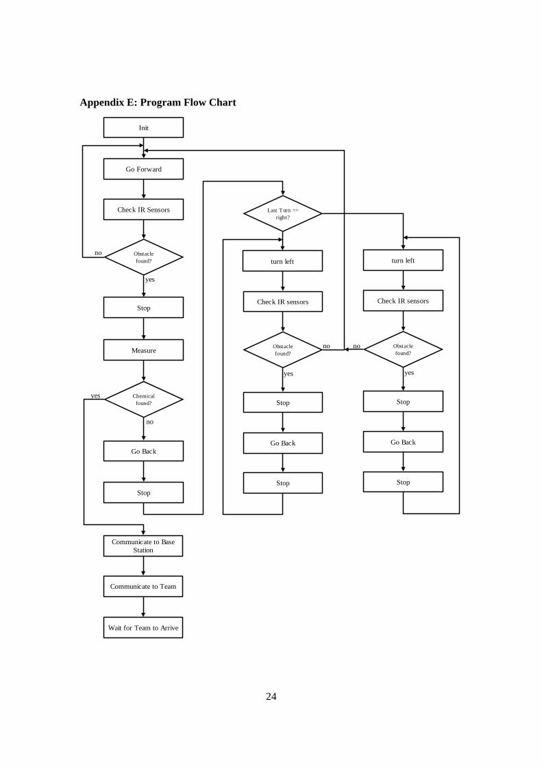
The local navigational methodology was made simple due to the limited amount
of memory available, yet it tried to yield and effective search algorithm. The algorithm
was designed to produce a sweeping pattern across the playing field, stopping if an
obstacle was detected the checking if was a chemical source, Appendix I: Navigation
Diagrams. If it was not the chemical source, the chemical measurement did not meet the
threshold, the vehicle would make a 180 degree turn. These turns would alternate left
and right when obstacles are detected. If the chemical threshold is detected, then the
vehicle will stop, transmit to the base station that the target is found, transmit to the
partner vehicle that the target is found and emit an infrared beacon for the partner vehicle
to follow.
f. Communication
The communication utilized the serial communication lines available on the
Motorola M68HC11E9 and one output line, functioning as a select pin. The data was
simply broad cast within the protocol, waiting for acknowledges from the receiver of the
data after the transmission is complete. When data is received from the transceiver over
the serial line, an interrupt is generated. This function was enabled to avoid polling the
serial status register for new data. The protocol created, Appendix J: Communication
16
Protocol, was followed in the receive using a state machine, checking for the correct start
symbol, to-address, packet numbers, size, and message. The data was acknowledged
when all of these conditions were met.
g. Optimization
The main problem with the software design was the memory usage and allocation.
The initial design was ambitious for the limited 512 bytes of EEPROM and 512 bytes of
RAM. This required the simplification of complex modules and the use of efficient
programming techniques and insightful use of RAM and EEPROM.
VII. Conclusions
The current methods to identify and track an entity have largely been confined to
the physical spectrum. Through inspection of biological methods, it is observed that
many predators hunt using the discrimination of scent, a chemical method. This
approach is particularly useful since one retains the ability to follow a target, and also in
many instances remain out of the target’s visual, audible, and many times the target’s
olfactory ranges. This gives the predator the element of surprise, evading the natural
defense mechanisms of the prey.
The autonomous search vehicle given a minimal amount of resources attempted to
approach this goal. Clearly the performance of the vehicle was limited to the amount of
data it could sense and the power of the logic the system contains. These factors are
linked directly to the systems memory and sensing capabilities. In this case the memory
was the limiting factor. The autonomous search vehicle addressed a series of deeper
issues: energy efficiency, wireless communication, and mechatronic design. Energy
efficiency is a key issue when dealing with a mobile platform that does not generate its
own power, the system requires a minimum of the maximum amount of energy to
complete the task, even though this is often not optimal, and a minimal amount of energy
consumption is desired. The use of wireless communication between sensing system to
yield a common goal can create significant increase in process efficiency, and the
redundant checking offers a layer of data verification. This was addressed in our project,
but unfortunately stands unverified. Mechatronic design seemed to be the largest issue
17
in this project, since the design factors were all interrelated. Through the consideration of
interdisciplinary factor in the original design, a superior design was achieved, Appendix
L: Final Result.
a. Future Research
The autonomous search vehicle offers a variety of paths for future research.
Primarily, improvements in better use of the sensor data and extending the research into
larger scale mobile sensor networks could be followed up. The distribution of
intelligence through out the system could offer one solution to the limited capabilities of
the microprocessor. Smart components could preprocess the data, creating a feature
based system, which allows for the reduction of code required to assess the data. Further,
greater navigational functionality could be implemented through the development of
positioning technique, so improved search algorithms could be executed.
18
VIII. References
Aktan, Comfort, and Shanis. Managing Multi-Hazard Risk at Metropolitan USA.
PIN PORT Direction Description 9 C 0 O 7 SEG CONTROL 1 10 1 O 7 SEG CONTROL 2 11 2 O 7 SEG CONTROL 3 12 3 O 7 SEG CONTROL 4 13 4 O 7 SEG DATA A 14 5 O 7 SEG DATA B 15 6 O 7 SEG DATA C 16 7 O 7 SEG DATA D 20 D 0 I RxD 21 1 O TxD 22 2 O R/T SELECT 23 3 O IR Transmitter 24 4 I IR Digital Distance Sensor 1 25 5 I IR Digital Distance Sensor 2 27 A 7 28 6 O PWM OC2 29 5 O PWM OC3 30 4 O PWM OC4 31 3 32 2 33 1 34 0 35 B 7 O LED 4 36 6 O LED 3 37 5 O LED 2 38 4 O LED 1 39 3 O LEFT 40 2 O RIGHT 41 1 O BACK 42 0 O FWD 43 E 0 I IR Analog Distance Sensor 1 44 4 I IR Transistor 1 45 1 I IR Analog Distance Sensor 2 46 5 I IR Transistor 2 47 2 I IR Analog Distance Sensor 3 48 6 I IR Transistor 3 49 3 I Chemical Sensor 1 50 7 I Chemical Sensor 2
28
Appendix I: Navigation Diagrams
Figure 8: Sweep 1
Figure 9: Sweep 2
29
Appendix J: Communication Protocol
Table 5: Communication Protocol
Protocol DataPreamble 0xFFStart Symbol 0x7ETo/From 0x67Packet Number 0x01Size/Status 0x01Message 0x01FCS 0x01


![FINAL PROJECT REPORT1[1]](https://static.documents.pub/doc/80x56/549e4753b37959af618b4682/final-project-report11.jpg)


